EP4545811A1 - Rivet and method for producing a rivet connection - Google Patents
Rivet and method for producing a rivet connection Download PDFInfo
- Publication number
- EP4545811A1 EP4545811A1 EP23205312.4A EP23205312A EP4545811A1 EP 4545811 A1 EP4545811 A1 EP 4545811A1 EP 23205312 A EP23205312 A EP 23205312A EP 4545811 A1 EP4545811 A1 EP 4545811A1
- Authority
- EP
- European Patent Office
- Prior art keywords
- rivet
- coating
- projection
- layer
- head
- Prior art date
- Legal status (The legal status is an assumption and is not a legal conclusion. Google has not performed a legal analysis and makes no representation as to the accuracy of the status listed.)
- Pending
Links
Images
Classifications
-
- F—MECHANICAL ENGINEERING; LIGHTING; HEATING; WEAPONS; BLASTING
- F16—ENGINEERING ELEMENTS AND UNITS; GENERAL MEASURES FOR PRODUCING AND MAINTAINING EFFECTIVE FUNCTIONING OF MACHINES OR INSTALLATIONS; THERMAL INSULATION IN GENERAL
- F16B—DEVICES FOR FASTENING OR SECURING CONSTRUCTIONAL ELEMENTS OR MACHINE PARTS TOGETHER, e.g. NAILS, BOLTS, CIRCLIPS, CLAMPS, CLIPS OR WEDGES; JOINTS OR JOINTING
- F16B19/00—Bolts without screw-thread; Pins, including deformable elements; Rivets
- F16B19/04—Rivets; Spigots or the like fastened by riveting
- F16B19/08—Hollow rivets; Multi-part rivets
- F16B19/086—Self-piercing rivets
-
- B—PERFORMING OPERATIONS; TRANSPORTING
- B21—MECHANICAL METAL-WORKING WITHOUT ESSENTIALLY REMOVING MATERIAL; PUNCHING METAL
- B21J—FORGING; HAMMERING; PRESSING METAL; RIVETING; FORGE FURNACES
- B21J15/00—Riveting
- B21J15/02—Riveting procedures
- B21J15/025—Setting self-piercing rivets
-
- F—MECHANICAL ENGINEERING; LIGHTING; HEATING; WEAPONS; BLASTING
- F16—ENGINEERING ELEMENTS AND UNITS; GENERAL MEASURES FOR PRODUCING AND MAINTAINING EFFECTIVE FUNCTIONING OF MACHINES OR INSTALLATIONS; THERMAL INSULATION IN GENERAL
- F16B—DEVICES FOR FASTENING OR SECURING CONSTRUCTIONAL ELEMENTS OR MACHINE PARTS TOGETHER, e.g. NAILS, BOLTS, CIRCLIPS, CLAMPS, CLIPS OR WEDGES; JOINTS OR JOINTING
- F16B19/00—Bolts without screw-thread; Pins, including deformable elements; Rivets
- F16B19/04—Rivets; Spigots or the like fastened by riveting
- F16B19/06—Solid rivets made in one piece
-
- F—MECHANICAL ENGINEERING; LIGHTING; HEATING; WEAPONS; BLASTING
- F16—ENGINEERING ELEMENTS AND UNITS; GENERAL MEASURES FOR PRODUCING AND MAINTAINING EFFECTIVE FUNCTIONING OF MACHINES OR INSTALLATIONS; THERMAL INSULATION IN GENERAL
- F16B—DEVICES FOR FASTENING OR SECURING CONSTRUCTIONAL ELEMENTS OR MACHINE PARTS TOGETHER, e.g. NAILS, BOLTS, CIRCLIPS, CLAMPS, CLIPS OR WEDGES; JOINTS OR JOINTING
- F16B2200/00—Constructional details of connections not covered for in other groups of this subclass
- F16B2200/79—Friction-reducing coatings
-
- F—MECHANICAL ENGINEERING; LIGHTING; HEATING; WEAPONS; BLASTING
- F16—ENGINEERING ELEMENTS AND UNITS; GENERAL MEASURES FOR PRODUCING AND MAINTAINING EFFECTIVE FUNCTIONING OF MACHINES OR INSTALLATIONS; THERMAL INSULATION IN GENERAL
- F16B—DEVICES FOR FASTENING OR SECURING CONSTRUCTIONAL ELEMENTS OR MACHINE PARTS TOGETHER, e.g. NAILS, BOLTS, CIRCLIPS, CLAMPS, CLIPS OR WEDGES; JOINTS OR JOINTING
- F16B5/00—Joining sheets or plates, e.g. panels, to one another or to strips or bars parallel to them
- F16B5/04—Joining sheets or plates, e.g. panels, to one another or to strips or bars parallel to them by means of riveting
Definitions
- the present invention relates to a rivet, notably a self-piercing rivet, and a method for producing a rivet connection, notably a punch rivet connection.
- rivet connection notably self-piercing riveting method using a self-piercing rivet, have been well-established for years, particularly in body manufacture.
- fastening tools adapted to set the rivet within a workpiece arrangement by means of a programmable handling device, such as a robot.
- a programmable handling device such as a robot
- the rivets it is likewise preferred for the rivets to be fed to a fastening tool attached to a robot arm.
- One rivet of the plurality of rivets from the magazine arrangement is moved to the fastening tool in order to be punched within a workpiece arrangement.
- the workpiece arrangement comprises an upper component and a lower component to be fastened.
- the upper and lower components are clamped and the self-piercing rivet held by the fastening tool is punched into the workpiece arrangement.
- a shaft of the self-piercing rivet pierces and penetrates the upper component.
- the shaft of the self-piercing rivet penetrating the upper component enters the lower component and the lower surface of the lower component comes into contact with the bottom of a die, the bottom of the die cavity pushes back the lower component.
- a hollow shaft of the self-piercing rivet receives a reaction force from the lower component and opens in a ring shape in the lower component without fully penetrating the lower component.
- a mechanical interlock is formed by opening the shaft of the self-piercing rivet, and the upper component and the lower component are mechanically fastened.
- the number of components to be fastened may be two, three or more.
- the rivet may be fastened in only one component.
- an adhesive is often applied between the components to be fastened in order to improve the performance with regard to load bearing capacity, crash stability, improved corrosion resistance, and Noise, Vibration, Harshness (NVH).
- rivets and more particularly self-piercing rivets are well-known and widely used, there is a constant need to improve such fasteners in order to provide reliable, easy to use and to manufacture rivets.
- Document EP2470799A1 for instance discloses a punch rivet adapted to be set in a workpiece arrangement of at least two workpieces.
- Such rivets are generally coated to provide a corrosion protection and anti-friction performances.
- Prior art document DE 10 2014 000 623 B4 discloses a self-piercing rivet which has a corrosion protection layer which is covered by a top layer which allows to adjust setting characteristics as friction and material flow.
- US2007196632 discloses an anti-friction coating adapted for fastener (and notably rivets) with a metal or alloy layer, over which a conversion coating layer is formed and a composite coating layer overlaying the conversion coating layer.
- the composite coating layer includes one or more lubricants.
- the present invention provides a rivet according to independent claim 1 and a method for joining components by means of a rivet according to claim 10.
- the rivet notably a self-piercing rivet, comprises a head with a top surface, a shaft longitudinally extending along a longitudinal axis and a transition portion between the shaft and the head.
- the rivet is integrally made in a metal material and comprises a three-layers coating adapted to prevent corrosion of said rivet.
- At least one projection is arranged on the top surface of the head.
- the presence of the at least one projection on the top surface prevent adhesion during the coating, , thus allowing the rivets to be easily transported and used in an automated system without impacting the rivet joint performances.
- the coating improves the friction coefficient and the resistance to corrosion.
- the at least one projection reduces the contact area (and therefore the surface contact) tremendously between two top surfaces of two different rivets when they face each other during the coating or the transport, for instance.
- the presence of the projection does not interfere with the setting process and parameters. More particularly, the projection may no longer be visible after the setting step.
- such a rivet may notably be easily and completely coated in bulks, without the risk of having completely or partially uncoated surfaces or damages to the coating due to a sticking aspect of the rivets during the coating. Indeed, for instance during a coating in bulks, if the rivet sticks together, there is a risk that no complete coating is provided to the sticked surfaces and/or a risk of damaging the coating when isolating the rivets from each other.
- the presence of the projection eliminates or mitigates this risk. Rivets can easily be bulk-coated in large numbers in a single charge, making manufacture less time-consuming and less costly.
- the outer circumference of the shaft and the head top surface are coated with the three-layers coating.
- the friction coefficient is of particular relevance in the area of the shaft of the rivet, and the head top surface needs to be coated in order to provide the necessary corrosion resistance.
- the three-layers coating comprises an electroplated coating layer, a passivation layer and a top coat layer.
- the zinc nickel layer is an anti-corrosion layer and the top coat layer reduces wear of friction.
- the electroplated coating layer is a zinc nickel layer.
- the top coat layer is free of zinc and is applied over a water-soluble suspension.
- the passivation layer forms a non-metallic protection layer.
- the passivation layer forms a nickel-free inorganic conversion layer. This will change the electrochemical corrosion potential of the coating system.
- the zinc nickel layer comprises a nickel content between 8 and 20%, preferably 12% to 16%. This nickel content provides a good compromise between cost and corrosion resistance.
- the head has a planar head upper side which defines the top surface and a head diameter DH, and wherein one projection is centered on the top surface of the head.
- the centered projection can be easily manufactured and does not increase the manufacturing time or complexity.
- one projection extends on the entire top surface.
- a plurality of projections is provided and the projections are evenly distributed over the top surface. Thus, no tilting of the rivet during the setting occurs.
- the projection has a projection height Hp
- the rivet has a rivet height Ht between a rivet foot end and the top surface
- the projection height is between 1/500 and 1/50 of the rivet head diameter.
- the projection has a conical, pyramidal, semi-spherical shape.
- one projection is provided and the projection has a base defined by a portion of the top surface, and the base of the projection comprises a projection diameter between 1/2 and 1/10 of a head diameter.
- several projections are provided, and the projections all have a base defined by a portion of the top surface, each base comprises a projection diameter of less than 1/3 of the head diameter.
- the shaft is a hollow or semi-hollow shaft open at a first end and having a shaft internal diameter and a shaft external diameter, and said shaft comprises at the first end an annular cutting edge defining a cutting-edge diameter smaller than the shaft external diameter, and the shaft internal diameter merges with the annular cutting edge via a cutting-edge radius.
- This geometry allows good joining performances, notably for high-strength materials.
- the annular cutting-edge merges with the shaft external diameter via a shaft outer chamfer which is oriented at a chamfer angle.
- the chamfer angle is of less than 45° in relation to a radial plane.
- the top coat layer is an organic coating, particularly an organic coating containing aluminum.
- the top coat layer is a friction control coating layer and has a friction coefficient in a range from 0.01 to 0.19, particularly in a range from 0.08 to 0.18, and preferably in a range from 0.12 to 0.18 or in range from 0.08 to 0.13.
- the third coating layer is applied via a dip-spin process.
- the at least one projection prevents the rivets from sticking during the dip-spin process.
- the present disclosure is also directed to a methos for joining components by means of a rivet which is deformed during the joining process.
- the projection is visible before the setting step, and after the setting step, the top surface is sensibly planar. The projection is plastically deformed during the setting step.
- the rivet 10 comprises a head 12.
- the head 12 has an axial length Ih of for example 1 mm.
- the head 12 comprises a top surface 14.
- the top surface 14 may for instance be circular and have a head diameter DH.
- the head diameter DH may be greater than 5 mm.
- the head diameter DH may be 5.5 mm or 7.75mm.
- the head has for instance a cylindrical head outer surface and a head thickness th.
- the head is connected to a shaft 16 through a transition portion 18.
- the transition portion 18 may have a radius between 1 and 2 mm.
- the shaft 16 is longitudinally extending along a longitudinal axis from the transition portion 18.
- the transition portion 18 is arranged opposed to the top surface 14.
- a projection 20 is arranged on the top surface 14.
- the projection 20 is depicted for instance in Fig. 2 .
- the projection 20 is defined by a shape, which does not offer a plane surface.
- the projection 20 may for instance be conical. In other embodiments, the projection may be pyramidal or may have a semi-spherical shape.
- the base 22 of the projection 20 is defined by a portion of the top surface 14.
- the projection 20 may comprise a projection base diameter Dp (corresponding to the diameter of the base of the projection formed on the top surface).
- the projection base diameter may for instance be between 1/2 and 1/10 of the head diameter DH. More particularly, a ratio of the projection base diameter Dp to the head diameter DH may be between 0.1 and 0.3.
- the projection 20 defines a projection height Hp.
- the projection base diameter may be between 0.9 and 1.3mm and the projection height may be between 0.02 and 0.04 mm.
- the projection base diameter may be between 1.2 and 1.6 mm and the projection height may be between 0.02 and 0.04 mm.
- the projection height Hp may be between 1/500 and 1/50 of the rivet head diameter.
- the rivet 10 may have more than one projection 20.
- Fig. 4 schematically shows the top surface of a rivet 10 with four projections 20.
- the projections 20 are for instance identical. In other embodiments, the projections may be different.
- the four projections are regularly distributed on the top surface.
- the rivet 10 may have a plurality of projections 20 and the projections 20 are arranged on the top surface in such a way that a tilting of the rivet during the setting step is avoid.
- the plurality of projections is regularly or evenly distributed over the top surface or the plurality of projection is arranged in a manner that a balance is created on the top surface, avoiding tilting during the setting step.
- the rivet 10 is made integrally in a metal material.
- the rivet is preferably from a unitary metal material, particularly steel.
- the rivet 10 is for instance made of 37MnB4.
- the rivet may have a hardness in a range from 220 ⁇ 30 HV10 to 590 ⁇ 30 HV10, particularly in a range from 380 ⁇ 30 HV10 to 510 ⁇ 30 HV10, measured as a Vickers hardness.
- the hardness may be in a range from below H0 to H6.
- the rivet 10 defines a rivet height or rivet length Ht.
- the rivet length Ht is defined between the rivet foot end and the top surface 14.
- the projection height Hp is for instance between 1/500 and 1/100 of the rivet height Ht.
- the shaft 16 may be a hollow or semi-hollow shaft open at a first end and having a shaft internal diameter and a shaft external diameter Ds.
- the shaft 16 may have an outer diameter between 3 and 6 millimeters.
- the internal diameter of the shaft 16 is smaller than the external diameter Ds.
- the shaft 16 may comprise at the first end an annular cutting edge 24 defining a cutting-edge diameter smaller than the shaft external diameter Ds.
- the shaft internal diameter merges with the annular cutting edge via a cutting-edge radius.
- the annular cutting-edge 24 may merge with the shaft external diameter Ds via a shaft outer chamfer which is oriented at a chamfer angle A.
- the chamfer angle A is for instance of less than 45 degrees.
- other rivet shapes and more particularly self-piercing rivet shapes may be provided.
- the rivet 10 If the rivet 10 is driven into a workpiece arrangement formed by stacked components, it pierces with its annular cutting edge into the upper component and, during the further joining process, the shaft fully penetrates the upper component. When the shaft enters the lower component, the lower surface of the lower component comes into contact with the bottom of the die, so as to create a reaction force. As a result, the hollow shaft of the rivet opens in a ring shape in the lower component without penetrating the lower component.
- the rivet 10 comprises a three-layers coating B1, B2, B3 adapted to prevent corrosion and better control the friction.
- the first coating layer B1 is for instance an electroplated coating layer.
- the first coating layer B1 is provided on the rivet body by means of electrolysis.
- the first coating layer may be a corrosion protection layer.
- the first coating layer is a zinc nickel layer.
- the first coating layer B1 may be a zinc-based coating or a nickel-based coating or a copper-based coating.
- the first coating layer is made of at least one material which is selected from the group which comprises: Zn, a Zn alloy, ZnNi, Ni, a Ni alloy, NiP, NiW, Cu, a Cu alloy, CuNi, , etc.
- the first coating layer may have a thickness in a range from 3 ⁇ m to 12 ⁇ m, particularly in a range from 5 ⁇ m to 10 ⁇ m.
- the second coating layer B2 is a passivation layer.
- the second coating layer B2 is provided on top of the first coating layer B1 by a passivation process.
- the passivation layer forms a non-metallic layer, for instance a non-metallic conversion layer.
- the passivation layer is for example a nickel-free inorganic conversion layer.
- the passivation layer provided on top of the base coating by a passivation process has a thickness which is preferably in a range from 50 nm to 400 nm.
- the passivation process is preferably a chemical process for reducing the reactivity of this layer and for delaying white rust formation or corrosion of the base coating.
- the third coating layer B3 is a friction control layer or a top coat layer.
- the third coating layer B3 is arranged on top of the passivation layer.
- the third layer controls the friction value, but also improves corrosion resistance, chemical resistance against acids, and acts as another isolation layer.
- the third coating layer is for instance applied via a dip-spin process. For instance, the rivet with the first and second coating layers is placed in a meshed basket. The mesh basket is then submerged into the coating solution. In a subsequent step, the mesh basket is removed from the coating solution and spun to remove any coating solution excess on the rivet. A plurality of rivets is coated during the dip-spin process.
- the projection allows notably during said dip-spin process to avoid the rivets to stick which each other, and notably that two different rivets stick to each other, which would for instance prevent a correct coating of the rivet surfaces.
- the third coating layer has friction control properties. It might be a lubricant only to ensure a correct friction behavior and electrical conductivity.
- the third coating layer B3 can also for instance be nickel-free.
- the third coating layer B3 is an organic coating, particularly an organic coating containing aluminum. Particularly, it is preferred if the third coating layer B3 is made of at least one material which is selected from the group which comprises: Magni B18, Torque'N'Tension, Microgleit DF 921, etc. Magni B18 is a well-known top coat.
- the third coating layer B3 has for example a friction coefficient in a range from 0.07 to 0.19, particularly in a range from 0.08 to 0.18, preferably in a range from 0.12 to 0.18 or in a range from 0.08 to 0.13.
- the third coating layer B3 may have a thickness in a range from 1 ⁇ m to 6 ⁇ m, particularly in a range from 2 ⁇ m to 4 ⁇ m.
- the coating is provided preferably on the entire surface of the rivet 10, although it is generally possible to provide the coating only in certain areas of the surface. Particularly, it is preferred if at least the outer circumference of the shaft 16 and the head top surface 14 are coated, because the friction coefficient is of particular relevance in the area of the shaft of the rivet, and because the head top surface needs to be coated in order to provide the necessary corrosion resistance. Preferably, a head underside radius and/or an annular cutting edge of the shaft and/or an annular radial end surface of the shaft are coated as well.
- the projection 20 prevents risks of adhesion or sticking between rivets.
- the projection 20 is easily manufactured during the manufacturing process of the rivet. Its shape and geometry do not influence the joining performance of the rivet, but sensibly increase its handling, storage and its use in automated processes. More particularly, the at least one projection, on the top surface, prevents the presence of a large plane surface more prone to sticking.
Landscapes
- Engineering & Computer Science (AREA)
- General Engineering & Computer Science (AREA)
- Mechanical Engineering (AREA)
- Insertion Pins And Rivets (AREA)
Abstract
Method for joining components by means of a rivet and rivet (10) for a riveted connection, in particular self-piercing rivet, comprising:
- a head (12) with a top surface (14),
- a shaft (16) longitudinally extending along a longitudinal axis,
- a transition portion (18) between the shaft and the head,
wherein the rivet (10) is integrally made in a metal material and comprises a coating (B1, B2, B3) adapted to prevent corrosion of said rivet, and wherein at least one projection (20) is arranged on the top surface (14) of the head.
- a head (12) with a top surface (14),
- a shaft (16) longitudinally extending along a longitudinal axis,
- a transition portion (18) between the shaft and the head,
wherein the rivet (10) is integrally made in a metal material and comprises a coating (B1, B2, B3) adapted to prevent corrosion of said rivet, and wherein at least one projection (20) is arranged on the top surface (14) of the head.
Description
- The present invention relates to a rivet, notably a self-piercing rivet, and a method for producing a rivet connection, notably a punch rivet connection.
- In the field of fastening technology, it is known to make joints using rivets. Especially in the field of automotive engineering, rivet connection, notably self-piercing riveting method using a self-piercing rivet, have been well-established for years, particularly in body manufacture.
- In high-volume production it is preferred to move the fastening tools adapted to set the rivet within a workpiece arrangement by means of a programmable handling device, such as a robot. In this case it is likewise preferred for the rivets to be fed to a fastening tool attached to a robot arm. To this end, it is known to connect the fastening tool to a feeding device and to use a magazine arrangement for accommodating a plurality of rivets. One rivet of the plurality of rivets from the magazine arrangement is moved to the fastening tool in order to be punched within a workpiece arrangement.
- Usually, the workpiece arrangement comprises an upper component and a lower component to be fastened. The upper and lower components are clamped and the self-piercing rivet held by the fastening tool is punched into the workpiece arrangement. A shaft of the self-piercing rivet pierces and penetrates the upper component. When the shaft of the self-piercing rivet penetrating the upper component enters the lower component and the lower surface of the lower component comes into contact with the bottom of a die, the bottom of the die cavity pushes back the lower component. As a result, a hollow shaft of the self-piercing rivet receives a reaction force from the lower component and opens in a ring shape in the lower component without fully penetrating the lower component. A mechanical interlock is formed by opening the shaft of the self-piercing rivet, and the upper component and the lower component are mechanically fastened.
- The number of components to be fastened may be two, three or more. Eventually, the rivet may be fastened in only one component. For example, in the case of three components, at least the uppermost component is fully penetrated, and the lowermost component is not fully penetrated. In the production of automobiles, an adhesive is often applied between the components to be fastened in order to improve the performance with regard to load bearing capacity, crash stability, improved corrosion resistance, and Noise, Vibration, Harshness (NVH).
- Although rivets, and more particularly self-piercing rivets are well-known and widely used, there is a constant need to improve such fasteners in order to provide reliable, easy to use and to manufacture rivets.
- Document
EP2470799A1 for instance discloses a punch rivet adapted to be set in a workpiece arrangement of at least two workpieces. - Such rivets are generally coated to provide a corrosion protection and anti-friction performances.
- Prior
art document DE 10 2014 000 623 B4 discloses a self-piercing rivet which has a corrosion protection layer which is covered by a top layer which allows to adjust setting characteristics as friction and material flow. -
US2007196632 discloses an anti-friction coating adapted for fastener (and notably rivets) with a metal or alloy layer, over which a conversion coating layer is formed and a composite coating layer overlaying the conversion coating layer. The composite coating layer includes one or more lubricants. - However, there is still a need to improve the current fasteners and provide a rivet which ensures reliable setting behavior during the riveting process, while reducing the coefficient of friction, and reducing the dust in the setting tools and equipment. The rivet also needs to be easily coated in bulks to be quickly manufactured in an automated process.
- Accordingly, the present invention provides a rivet according to
independent claim 1 and a method for joining components by means of a rivet according toclaim 10. More particularly, the rivet, notably a self-piercing rivet, comprises a head with a top surface, a shaft longitudinally extending along a longitudinal axis and a transition portion between the shaft and the head. The rivet is integrally made in a metal material and comprises a three-layers coating adapted to prevent corrosion of said rivet. At least one projection is arranged on the top surface of the head. The presence of the at least one projection on the top surface, as claimed, prevent adhesion during the coating, , thus allowing the rivets to be easily transported and used in an automated system without impacting the rivet joint performances. The coating improves the friction coefficient and the resistance to corrosion. No additional treatment on top is needed. The at least one projection reduces the contact area (and therefore the surface contact) tremendously between two top surfaces of two different rivets when they face each other during the coating or the transport, for instance. The presence of the projection does not interfere with the setting process and parameters. More particularly, the projection may no longer be visible after the setting step. Thus, such a rivet may notably be easily and completely coated in bulks, without the risk of having completely or partially uncoated surfaces or damages to the coating due to a sticking aspect of the rivets during the coating. Indeed, for instance during a coating in bulks, if the rivet sticks together, there is a risk that no complete coating is provided to the sticked surfaces and/or a risk of damaging the coating when isolating the rivets from each other. The presence of the projection eliminates or mitigates this risk. Rivets can easily be bulk-coated in large numbers in a single charge, making manufacture less time-consuming and less costly. - In an embodiment, the outer circumference of the shaft and the head top surface are coated with the three-layers coating. For instance, in case of a hollow or semi-hollow shaft, there is no need to coat the internal surface of the shaft. Besides, the friction coefficient is of particular relevance in the area of the shaft of the rivet, and the head top surface needs to be coated in order to provide the necessary corrosion resistance.
- In an embodiment, the three-layers coating comprises an electroplated coating layer, a passivation layer and a top coat layer. The zinc nickel layer is an anti-corrosion layer and the top coat layer reduces wear of friction.
- In an embodiment, the electroplated coating layer is a zinc nickel layer. In an embodiment, the top coat layer is free of zinc and is applied over a water-soluble suspension.
- In an embodiment, the passivation layer forms a non-metallic protection layer. For example, the passivation layer forms a nickel-free inorganic conversion layer. This will change the electrochemical corrosion potential of the coating system.
- In an embodiment, the zinc nickel layer comprises a nickel content between 8 and 20%, preferably 12% to 16%. This nickel content provides a good compromise between cost and corrosion resistance.
- In an embodiment, the head has a planar head upper side which defines the top surface and a head diameter DH, and wherein one projection is centered on the top surface of the head. The centered projection can be easily manufactured and does not increase the manufacturing time or complexity. In an embodiment, one projection extends on the entire top surface. In an embodiment, a plurality of projections is provided and the projections are evenly distributed over the top surface. Thus, no tilting of the rivet during the setting occurs.
- In an embodiment, the projection has a projection height Hp, the rivet has a rivet height Ht between a rivet foot end and the top surface, and the projection height is between 1/500 and 1/50 of the rivet head diameter. Such range allows the projection to indeed have an impact on the rivet adhesion (or sticking effect) without influencing the rivet performances during the setting.
- In an embodiment, the projection has a conical, pyramidal, semi-spherical shape.
- For instance, one projection is provided and the projection has a base defined by a portion of the top surface, and the base of the projection comprises a projection diameter between 1/2 and 1/10 of a head diameter. In an alternative embodiment, several projections are provided, and the projections all have a base defined by a portion of the top surface, each base comprises a projection diameter of less than 1/3 of the head diameter.
- In an embodiment, the shaft is a hollow or semi-hollow shaft open at a first end and having a shaft internal diameter and a shaft external diameter, and said shaft comprises at the first end an annular cutting edge defining a cutting-edge diameter smaller than the shaft external diameter, and the shaft internal diameter merges with the annular cutting edge via a cutting-edge radius. This geometry allows good joining performances, notably for high-strength materials.
- In an embodiment, the annular cutting-edge merges with the shaft external diameter via a shaft outer chamfer which is oriented at a chamfer angle.
- In an embodiment, wherein the chamfer angle is of less than 45° in relation to a radial plane.
- In an embodiment, the top coat layer is an organic coating, particularly an organic coating containing aluminum. In an embodiment, the top coat layer is a friction control coating layer and has a friction coefficient in a range from 0.01 to 0.19, particularly in a range from 0.08 to 0.18, and preferably in a range from 0.12 to 0.18 or in range from 0.08 to 0.13.
- In an embodiment, the third coating layer is applied via a dip-spin process. The at least one projection prevents the rivets from sticking during the dip-spin process.
- The present disclosure is also directed to a methos for joining components by means of a rivet which is deformed during the joining process. In an embodiment, the projection is visible before the setting step, and after the setting step, the top surface is sensibly planar. The projection is plastically deformed during the setting step.
- The invention and its advantages will be better understood from the reading of the following description, given by way of example only and with reference to the accompanying drawings, of which:
-
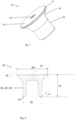
Fig. 1 shows a perspective view of the rivet according to the invention; -
Fig. 2 shows a side view of the rivet ofFig. 1 ; -
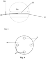
Fig. 3 shows the detail III ofFig. 2 ; -
Fig. 4 schematically shows a top surface of a rivet with a plurality of projections according to a second embodiment. - The embodiments of the disclosure will be best understood by reference to the drawings, wherein the same reference signs designate identical or similar elements. It will be readily understood that the components of the disclosed embodiments, as generally described and illustrated in the figures herein, could be arranged and designed in a wide variety of different configurations. Thus, the following detailed description of the embodiments of the systems and methods of the disclosure is not intended to limit the scope of the disclosure, as claimed, but is merely representative of possible embodiments of the disclosure.
-
Fig. 1 and Fig. 2 show arivet 10 adapted to join together a workpiece arrangement comprising for instance a first and a second workpiece.Fig. 1 shows more particularly a self-piercingrivet 10. - The
rivet 10 comprises ahead 12. Thehead 12 has an axial length Ih of for example 1 mm. Thehead 12 comprises atop surface 14. Thetop surface 14 may for instance be circular and have a head diameter DH. The head diameter DH may be greater than 5 mm. For instance, the head diameter DH may be 5.5 mm or 7.75mm. The head has for instance a cylindrical head outer surface and a head thickness th. The head is connected to ashaft 16 through atransition portion 18. Thetransition portion 18 may have a radius between 1 and 2 mm. Theshaft 16 is longitudinally extending along a longitudinal axis from thetransition portion 18. Thetransition portion 18 is arranged opposed to thetop surface 14. - A
projection 20 is arranged on thetop surface 14. Theprojection 20 is depicted for instance inFig. 2 . Theprojection 20 is defined by a shape, which does not offer a plane surface. Theprojection 20 may for instance be conical. In other embodiments, the projection may be pyramidal or may have a semi-spherical shape. Thebase 22 of theprojection 20 is defined by a portion of thetop surface 14. Theprojection 20 may comprise a projection base diameter Dp (corresponding to the diameter of the base of the projection formed on the top surface). The projection base diameter may for instance be between 1/2 and 1/10 of the head diameter DH. More particularly, a ratio of the projection base diameter Dp to the head diameter DH may be between 0.1 and 0.3. Theprojection 20 defines a projection height Hp. For instance, for a head diameter of 5.5mm, the projection base diameter may be between 0.9 and 1.3mm and the projection height may be between 0.02 and 0.04 mm. For a rivet with a head diameter of 7.75 mm, the projection base diameter may be between 1.2 and 1.6 mm and the projection height may be between 0.02 and 0.04 mm. More generally, the projection height Hp may be between 1/500 and 1/50 of the rivet head diameter. - More generally, the
rivet 10 may have more than oneprojection 20. -
Fig. 4 schematically shows the top surface of arivet 10 with fourprojections 20. Theprojections 20 are for instance identical. In other embodiments, the projections may be different. As depicted inFig. 4 , the four projections are regularly distributed on the top surface. More particularly, therivet 10 may have a plurality ofprojections 20 and theprojections 20 are arranged on the top surface in such a way that a tilting of the rivet during the setting step is avoid. For instance, the plurality of projections is regularly or evenly distributed over the top surface or the plurality of projection is arranged in a manner that a balance is created on the top surface, avoiding tilting during the setting step. - The
rivet 10 is made integrally in a metal material. The rivet is preferably from a unitary metal material, particularly steel. Therivet 10 is for instance made of 37MnB4. The rivet may have a hardness in a range from 220 ± 30 HV10 to 590 ± 30 HV10, particularly in a range from 380 ± 30 HV10 to 510 ± 30 HV10, measured as a Vickers hardness. The hardness may be in a range from below H0 to H6. - The
rivet 10 defines a rivet height or rivet length Ht. For instance the rivet length Ht is defined between the rivet foot end and thetop surface 14. The projection height Hp is for instance between 1/500 and 1/100 of the rivet height Ht. - As depicted in the figures, the
shaft 16 may be a hollow or semi-hollow shaft open at a first end and having a shaft internal diameter and a shaft external diameter Ds. Theshaft 16 may have an outer diameter between 3 and 6 millimeters. The internal diameter of theshaft 16 is smaller than the external diameter Ds. Theshaft 16 may comprise at the first end anannular cutting edge 24 defining a cutting-edge diameter smaller than the shaft external diameter Ds. The shaft internal diameter merges with the annular cutting edge via a cutting-edge radius. The annular cutting-edge 24 may merge with the shaft external diameter Ds via a shaft outer chamfer which is oriented at a chamfer angle A. The chamfer angle A is for instance of less than 45 degrees. In other embodiment, other rivet shapes and more particularly self-piercing rivet shapes may be provided. - If the
rivet 10 is driven into a workpiece arrangement formed by stacked components, it pierces with its annular cutting edge into the upper component and, during the further joining process, the shaft fully penetrates the upper component. When the shaft enters the lower component, the lower surface of the lower component comes into contact with the bottom of the die, so as to create a reaction force. As a result, the hollow shaft of the rivet opens in a ring shape in the lower component without penetrating the lower component. - The
rivet 10 comprises a three-layers coating B1, B2, B3 adapted to prevent corrosion and better control the friction. - The first coating layer B1 is for instance an electroplated coating layer. In other words, the first coating layer B1 is provided on the rivet body by means of electrolysis. The first coating layer may be a corrosion protection layer. For example, the first coating layer is a zinc nickel layer. In other embodiment, the first coating layer B1 may be a zinc-based coating or a nickel-based coating or a copper-based coating. For example, the first coating layer is made of at least one material which is selected from the group which comprises: Zn, a Zn alloy, ZnNi, Ni, a Ni alloy, NiP, NiW, Cu, a Cu alloy, CuNi, , etc. The first coating layer may have a thickness in a range from 3 µm to 12 µm, particularly in a range from 5 µm to 10 µm.
- The second coating layer B2 is a passivation layer. The second coating layer B2 is provided on top of the first coating layer B1 by a passivation process. The passivation layer forms a non-metallic layer, for instance a non-metallic conversion layer. The passivation layer is for example a nickel-free inorganic conversion layer. The passivation layer provided on top of the base coating by a passivation process has a thickness which is preferably in a range from 50 nm to 400 nm. The passivation process is preferably a chemical process for reducing the reactivity of this layer and for delaying white rust formation or corrosion of the base coating.
- The third coating layer B3 is a friction control layer or a top coat layer. The third coating layer B3 is arranged on top of the passivation layer. The third layer controls the friction value, but also improves corrosion resistance, chemical resistance against acids, and acts as another isolation layer. The third coating layer is for instance applied via a dip-spin process. For instance, the rivet with the first and second coating layers is placed in a meshed basket. The mesh basket is then submerged into the coating solution. In a subsequent step, the mesh basket is removed from the coating solution and spun to remove any coating solution excess on the rivet. A plurality of rivets is coated during the dip-spin process. The projection allows notably during said dip-spin process to avoid the rivets to stick which each other, and notably that two different rivets stick to each other, which would for instance prevent a correct coating of the rivet surfaces. The third coating layer has friction control properties. It might be a lubricant only to ensure a correct friction behavior and electrical conductivity. The third coating layer B3 can also for instance be nickel-free.. The third coating layer B3 is an organic coating, particularly an organic coating containing aluminum. Particularly, it is preferred if the third coating layer B3 is made of at least one material which is selected from the group which comprises: Magni B18, Torque'N'Tension, Microgleit DF 921, etc. Magni B18 is a well-known top coat. The same applies to the other above-listed coating materials of other manufacturers. The third coating layer B3 has for example a friction coefficient in a range from 0.07 to 0.19, particularly in a range from 0.08 to 0.18, preferably in a range from 0.12 to 0.18 or in a range from 0.08 to 0.13. The third coating layer B3 may have a thickness in a range from 1 µm to 6 µm, particularly in a range from 2 µm to 4 µm.
- The coating is provided preferably on the entire surface of the
rivet 10, although it is generally possible to provide the coating only in certain areas of the surface. Particularly, it is preferred if at least the outer circumference of theshaft 16 and the headtop surface 14 are coated, because the friction coefficient is of particular relevance in the area of the shaft of the rivet, and because the head top surface needs to be coated in order to provide the necessary corrosion resistance. Preferably, a head underside radius and/or an annular cutting edge of the shaft and/or an annular radial end surface of the shaft are coated as well. - The coating having a sticky finish, the
projection 20 prevents risks of adhesion or sticking between rivets. Theprojection 20 is easily manufactured during the manufacturing process of the rivet. Its shape and geometry do not influence the joining performance of the rivet, but sensibly increase its handling, storage and its use in automated processes. More particularly, the at least one projection, on the top surface, prevents the presence of a large plane surface more prone to sticking. - rivet 10
-
head 12 - axial length Ih
-
top surface 14 - head diameter DH
- head thickness th
-
shaft 16 -
transition portion 18 -
projection 20 -
base 22 - projection base diameter Dp
- projection height Hp
- rivet height or rivet length Ht
- shaft external diameter Ds
-
annular cutting edge 24 - three-layers coating B1, B2, B3
Claims (12)
- Rivet (10) for a riveted connection, in particular self-piercing rivet, comprising:- a head (12) with a top surface (14),- a shaft (16) longitudinally extending along a longitudinal axis,- a transition portion (18) between the shaft and the head,wherein the rivet (10) is integrally made in a metal material and comprises a coating (B1, B2, B3) adapted to prevent corrosion of said rivet, and wherein at least one projection (20) is arranged on the top surface (14) of the head.
- Rivet (10) according to claim 1, wherein the coating is a three-layers coating, and wherein the outer circumference of the shaft and the head top surface are coated with the three-layers coating (B1, B2, B3).
- Rivet (10) according to claim 2, wherein the three-layers coating (B1, B2, B3) comprises an electroplated coating layer, a passivation layer and a top coat layer.
- Rivet (10) according to claim 3, wherein the electroplated coating layer is a zinc nickel layer.
- Rivet (10) according to claim 4, wherein the zinc nickel layer comprises a nickel content between 8 and 20%, preferably 12% to 16%.
- Rivet (10) according to any of claims 2 to 5, wherein the third coating layer is a top coat layer, and wherein the top coat layer is an organic coating, particularly an organic coating containing aluminum.
- Rivet (10) according to any of claims 2 to 6, wherein the third coating layer is applied via a dip-spin process.
- Rivet (10) according to any of claims 1 to 7, wherein the top coat layer is a friction control coating layer and has a friction coefficient in a range from 0.01 to 0.19, particularly in a range from 0.08 to 0.18, and preferably in a range from 0.12 to 0.18 or in range from 0.08 to 0.13.
- Rivet (10) according to any of claims 1 to 8, wherein the projection (20) has a projection height Hp, wherein the rivet has a head diameter DH, and wherein the projection height Hp is between 1/500 and 1/50 of the rivet head diameter DH.
- Rivet (10) according to any of claims 1 to 9, wherein the rivet comprises a plurality of projections (20) which are regularly distributed over the top surface.
- Method for joining components by means of a rivet (10) which is deformed during the joining process, comprising the following steps:- providing a rivet according to any of claims 1 to 10,- providing a workpiece arrangement with components,- automatically setting the rivet within the workpiece arrangement.
- Method according to claim 11, wherein the at least one projection (20) is plastically deformed during the setting step.
Priority Applications (2)
| Application Number | Priority Date | Filing Date | Title |
|---|---|---|---|
| EP23205312.4A EP4545811A1 (en) | 2023-10-23 | 2023-10-23 | Rivet and method for producing a rivet connection |
| PCT/EP2024/079141 WO2025087756A1 (en) | 2023-10-23 | 2024-10-16 | Rivet and method for producing a rivet connection |
Applications Claiming Priority (1)
| Application Number | Priority Date | Filing Date | Title |
|---|---|---|---|
| EP23205312.4A EP4545811A1 (en) | 2023-10-23 | 2023-10-23 | Rivet and method for producing a rivet connection |
Publications (1)
| Publication Number | Publication Date |
|---|---|
| EP4545811A1 true EP4545811A1 (en) | 2025-04-30 |
Family
ID=88511507
Family Applications (1)
| Application Number | Title | Priority Date | Filing Date |
|---|---|---|---|
| EP23205312.4A Pending EP4545811A1 (en) | 2023-10-23 | 2023-10-23 | Rivet and method for producing a rivet connection |
Country Status (2)
| Country | Link |
|---|---|
| EP (1) | EP4545811A1 (en) |
| WO (1) | WO2025087756A1 (en) |
Citations (5)
| Publication number | Priority date | Publication date | Assignee | Title |
|---|---|---|---|---|
| US5680690A (en) * | 1996-02-06 | 1997-10-28 | Franklin S. Briles | Coated rivet and deformation thereof |
| US20070196632A1 (en) | 2006-02-23 | 2007-08-23 | Meyer William H Jr | Antifriction coatings, methods of producing such coatings and articles including such coatings |
| EP2470799A1 (en) | 2009-08-24 | 2012-07-04 | Newfrey LLC | Punch rivet, method for producing a punch rivet connection, and workpiece arrangement |
| US20160123362A1 (en) * | 2013-07-22 | 2016-05-05 | Kabushiki Kaisha Kobe Seiko Sho (Kobe Steel, Ltd.) | Rivet for connecting different materials, member for connecting different materials, method for manufacturing joined body of different materials, and joined body of different materials |
| DE102014000623B4 (en) | 2014-01-18 | 2018-09-27 | Audi Ag | Halbhohlnietelement |
-
2023
- 2023-10-23 EP EP23205312.4A patent/EP4545811A1/en active Pending
-
2024
- 2024-10-16 WO PCT/EP2024/079141 patent/WO2025087756A1/en active Pending
Patent Citations (5)
| Publication number | Priority date | Publication date | Assignee | Title |
|---|---|---|---|---|
| US5680690A (en) * | 1996-02-06 | 1997-10-28 | Franklin S. Briles | Coated rivet and deformation thereof |
| US20070196632A1 (en) | 2006-02-23 | 2007-08-23 | Meyer William H Jr | Antifriction coatings, methods of producing such coatings and articles including such coatings |
| EP2470799A1 (en) | 2009-08-24 | 2012-07-04 | Newfrey LLC | Punch rivet, method for producing a punch rivet connection, and workpiece arrangement |
| US20160123362A1 (en) * | 2013-07-22 | 2016-05-05 | Kabushiki Kaisha Kobe Seiko Sho (Kobe Steel, Ltd.) | Rivet for connecting different materials, member for connecting different materials, method for manufacturing joined body of different materials, and joined body of different materials |
| DE102014000623B4 (en) | 2014-01-18 | 2018-09-27 | Audi Ag | Halbhohlnietelement |
Also Published As
| Publication number | Publication date |
|---|---|
| WO2025087756A1 (en) | 2025-05-01 |
Similar Documents
| Publication | Publication Date | Title |
|---|---|---|
| US10751787B2 (en) | Method for forming a joint using a self-piercing rivet | |
| RU2512812C2 (en) | Component assembly comprising fastening element and part from sheet metal, and also method for making such component assembly | |
| EP3026273A1 (en) | Rivet for connecting different materials, member for connecting different materials, method for manufacturing joined body of different materials, and joined body of different materials | |
| US7380326B2 (en) | Method of attaching a self-attaching fastener to a panel | |
| US4825527A (en) | Method of attaching an element to a panel | |
| US7878746B2 (en) | Functional element, assembling component consisting of the functional element combined with a metal sheet, method for producing the assembly component and method for producing the functional element | |
| US11833576B2 (en) | Riveting method | |
| WO2007132194A1 (en) | Self-piercing riveting | |
| KR19990063694A (en) | Insertion method of fastener member, bolt member, riveting die and component assembly | |
| WO2001058617A1 (en) | Method and apparatus for manufacturing structures with improved fatigue life | |
| EP1767795A1 (en) | Self-attaching fastener | |
| WO2020057835A1 (en) | Self-piercing rivet | |
| EP3287210A2 (en) | Self-piercing rivet, arrangement with a self-piercing rivet and method for forming a joint | |
| WO2025087756A1 (en) | Rivet and method for producing a rivet connection | |
| US10792721B1 (en) | Method for manufacturing a work piece | |
| CN122070425A (en) | Rivet and method for producing a riveted connection | |
| US6842962B1 (en) | Sheet joining method and apparatus and a rivet for use in the method | |
| WO2018041961A1 (en) | A press-in element, a component assembly comprising the press-in element and a stack of panels and a method of manufacturing the component assembly | |
| EP4513045A1 (en) | Joining method and self-piercing joining element | |
| US20220305546A1 (en) | Self-piercing riveting die for magnesium alloy die castings | |
| US12098736B2 (en) | Self-piercing rivet joint and self-piercing rivet | |
| EP3748171B1 (en) | Self-piercing rivet | |
| US12078199B2 (en) | Self-punching functional element, component assembly and method of manufacturing a component assembly | |
| CN120777266A (en) | High-strength closed type locking rivet and manufacturing method thereof | |
| JP2007160389A (en) | Machine element joining method |
Legal Events
| Date | Code | Title | Description |
|---|---|---|---|
| PUAI | Public reference made under article 153(3) epc to a published international application that has entered the european phase |
Free format text: ORIGINAL CODE: 0009012 |
|
| STAA | Information on the status of an ep patent application or granted ep patent |
Free format text: STATUS: THE APPLICATION HAS BEEN PUBLISHED |
|
| AK | Designated contracting states |
Kind code of ref document: A1 Designated state(s): AL AT BE BG CH CY CZ DE DK EE ES FI FR GB GR HR HU IE IS IT LI LT LU LV MC ME MK MT NL NO PL PT RO RS SE SI SK SM TR |
|
| STAA | Information on the status of an ep patent application or granted ep patent |
Free format text: STATUS: REQUEST FOR EXAMINATION WAS MADE |
|
| 17P | Request for examination filed |
Effective date: 20251029 |