EP4545810A1 - Attachment clip for fastening an object on a rail - Google Patents
Attachment clip for fastening an object on a rail Download PDFInfo
- Publication number
- EP4545810A1 EP4545810A1 EP23205961.8A EP23205961A EP4545810A1 EP 4545810 A1 EP4545810 A1 EP 4545810A1 EP 23205961 A EP23205961 A EP 23205961A EP 4545810 A1 EP4545810 A1 EP 4545810A1
- Authority
- EP
- European Patent Office
- Prior art keywords
- attachment
- guiding
- attachment clip
- brake
- clip
- Prior art date
- Legal status (The legal status is an assumption and is not a legal conclusion. Google has not performed a legal analysis and makes no representation as to the accuracy of the status listed.)
- Pending
Links
Images

Classifications
-
- B—PERFORMING OPERATIONS; TRANSPORTING
- B64—AIRCRAFT; AVIATION; COSMONAUTICS
- B64D—EQUIPMENT FOR FITTING IN OR TO AIRCRAFT; FLIGHT SUITS; PARACHUTES; ARRANGEMENT OR MOUNTING OF POWER PLANTS OR PROPULSION TRANSMISSIONS IN AIRCRAFT
- B64D11/00—Passenger or crew accommodation; Flight-deck installations not otherwise provided for
- B64D11/003—Stowage devices for passengers' personal luggage
-
- B—PERFORMING OPERATIONS; TRANSPORTING
- B64—AIRCRAFT; AVIATION; COSMONAUTICS
- B64D—EQUIPMENT FOR FITTING IN OR TO AIRCRAFT; FLIGHT SUITS; PARACHUTES; ARRANGEMENT OR MOUNTING OF POWER PLANTS OR PROPULSION TRANSMISSIONS IN AIRCRAFT
- B64D11/00—Passenger or crew accommodation; Flight-deck installations not otherwise provided for
- B64D11/06—Arrangements of seats, or adaptations or details specially adapted for aircraft seats
- B64D11/0627—Seats combined with storage means
- B64D11/0629—Seats combined with storage means the storage means being specially adapted for emergency equipment
- B64D11/0632—Seats combined with storage means the storage means being specially adapted for emergency equipment for breathing apparatus
-
- F—MECHANICAL ENGINEERING; LIGHTING; HEATING; WEAPONS; BLASTING
- F16—ENGINEERING ELEMENTS AND UNITS; GENERAL MEASURES FOR PRODUCING AND MAINTAINING EFFECTIVE FUNCTIONING OF MACHINES OR INSTALLATIONS; THERMAL INSULATION IN GENERAL
- F16B—DEVICES FOR FASTENING OR SECURING CONSTRUCTIONAL ELEMENTS OR MACHINE PARTS TOGETHER, e.g. NAILS, BOLTS, CIRCLIPS, CLAMPS, CLIPS OR WEDGES; JOINTS OR JOINTING
- F16B2/00—Friction-grip releasable fastenings
- F16B2/20—Clips, i.e. with gripping action effected solely by the inherent resistance to deformation of the material of the fastening
- F16B2/22—Clips, i.e. with gripping action effected solely by the inherent resistance to deformation of the material of the fastening of resilient material, e.g. rubbery material
-
- F—MECHANICAL ENGINEERING; LIGHTING; HEATING; WEAPONS; BLASTING
- F16—ENGINEERING ELEMENTS AND UNITS; GENERAL MEASURES FOR PRODUCING AND MAINTAINING EFFECTIVE FUNCTIONING OF MACHINES OR INSTALLATIONS; THERMAL INSULATION IN GENERAL
- F16B—DEVICES FOR FASTENING OR SECURING CONSTRUCTIONAL ELEMENTS OR MACHINE PARTS TOGETHER, e.g. NAILS, BOLTS, CIRCLIPS, CLAMPS, CLIPS OR WEDGES; JOINTS OR JOINTING
- F16B5/00—Joining sheets or plates, e.g. panels, to one another or to strips or bars parallel to them
- F16B5/12—Fastening strips or bars to sheets or plates, e.g. rubber strips, decorative strips for motor vehicles, by means of clips
- F16B5/121—Fastening strips or bars to sheets or plates, e.g. rubber strips, decorative strips for motor vehicles, by means of clips fastened over the edge(s) of the sheet(s) or plate(s)
-
- F—MECHANICAL ENGINEERING; LIGHTING; HEATING; WEAPONS; BLASTING
- F16—ENGINEERING ELEMENTS AND UNITS; GENERAL MEASURES FOR PRODUCING AND MAINTAINING EFFECTIVE FUNCTIONING OF MACHINES OR INSTALLATIONS; THERMAL INSULATION IN GENERAL
- F16B—DEVICES FOR FASTENING OR SECURING CONSTRUCTIONAL ELEMENTS OR MACHINE PARTS TOGETHER, e.g. NAILS, BOLTS, CIRCLIPS, CLAMPS, CLIPS OR WEDGES; JOINTS OR JOINTING
- F16B7/00—Connections of rods or tubes, e.g. of non-circular section, mutually, including resilient connections
- F16B7/04—Clamping or clipping connections
- F16B7/0433—Clamping or clipping connections for rods or tubes being in parallel relationship
-
- B—PERFORMING OPERATIONS; TRANSPORTING
- B64—AIRCRAFT; AVIATION; COSMONAUTICS
- B64D—EQUIPMENT FOR FITTING IN OR TO AIRCRAFT; FLIGHT SUITS; PARACHUTES; ARRANGEMENT OR MOUNTING OF POWER PLANTS OR PROPULSION TRANSMISSIONS IN AIRCRAFT
- B64D2231/00—Emergency oxygen systems
-
- B—PERFORMING OPERATIONS; TRANSPORTING
- B64—AIRCRAFT; AVIATION; COSMONAUTICS
- B64D—EQUIPMENT FOR FITTING IN OR TO AIRCRAFT; FLIGHT SUITS; PARACHUTES; ARRANGEMENT OR MOUNTING OF POWER PLANTS OR PROPULSION TRANSMISSIONS IN AIRCRAFT
- B64D2231/00—Emergency oxygen systems
- B64D2231/02—Supply or distribution systems
- B64D2231/025—Oxygen masks; Mask storages; Features related to mask deployment
-
- F—MECHANICAL ENGINEERING; LIGHTING; HEATING; WEAPONS; BLASTING
- F16—ENGINEERING ELEMENTS AND UNITS; GENERAL MEASURES FOR PRODUCING AND MAINTAINING EFFECTIVE FUNCTIONING OF MACHINES OR INSTALLATIONS; THERMAL INSULATION IN GENERAL
- F16B—DEVICES FOR FASTENING OR SECURING CONSTRUCTIONAL ELEMENTS OR MACHINE PARTS TOGETHER, e.g. NAILS, BOLTS, CIRCLIPS, CLAMPS, CLIPS OR WEDGES; JOINTS OR JOINTING
- F16B2/00—Friction-grip releasable fastenings
- F16B2/005—Means to increase the friction-coefficient
-
- F—MECHANICAL ENGINEERING; LIGHTING; HEATING; WEAPONS; BLASTING
- F16—ENGINEERING ELEMENTS AND UNITS; GENERAL MEASURES FOR PRODUCING AND MAINTAINING EFFECTIVE FUNCTIONING OF MACHINES OR INSTALLATIONS; THERMAL INSULATION IN GENERAL
- F16B—DEVICES FOR FASTENING OR SECURING CONSTRUCTIONAL ELEMENTS OR MACHINE PARTS TOGETHER, e.g. NAILS, BOLTS, CIRCLIPS, CLAMPS, CLIPS OR WEDGES; JOINTS OR JOINTING
- F16B2/00—Friction-grip releasable fastenings
- F16B2/02—Clamps, i.e. with gripping action effected by positive means other than the inherent resistance to deformation of the material of the fastening
- F16B2/14—Clamps, i.e. with gripping action effected by positive means other than the inherent resistance to deformation of the material of the fastening using wedges
-
- F—MECHANICAL ENGINEERING; LIGHTING; HEATING; WEAPONS; BLASTING
- F16—ENGINEERING ELEMENTS AND UNITS; GENERAL MEASURES FOR PRODUCING AND MAINTAINING EFFECTIVE FUNCTIONING OF MACHINES OR INSTALLATIONS; THERMAL INSULATION IN GENERAL
- F16B—DEVICES FOR FASTENING OR SECURING CONSTRUCTIONAL ELEMENTS OR MACHINE PARTS TOGETHER, e.g. NAILS, BOLTS, CIRCLIPS, CLAMPS, CLIPS OR WEDGES; JOINTS OR JOINTING
- F16B7/00—Connections of rods or tubes, e.g. of non-circular section, mutually, including resilient connections
- F16B7/18—Connections of rods or tubes, e.g. of non-circular section, mutually, including resilient connections using screw-thread elements
- F16B7/187—Connections of rods or tubes, e.g. of non-circular section, mutually, including resilient connections using screw-thread elements with sliding nuts or other additional connecting members for joining profiles provided with grooves or channels
Definitions
- the present disclosure relates to systems for fastening an object to an attachment structure. More particularly, the present disclosure refers to systems comprising an attachment clip and an attachment structure for fastening an object to said attachment structure by said attachment clip.
- the cabin of an aircraft comprises devices to supply passengers with necessary functions, such as light, ventilation or oxygen in case of a loss of cabin pressure.
- Respective functional units may cover passenger supply/service units (PSUs) or oxygen containers, for example, that may be stored in a so-called passenger supply channel (PSC) of the aircraft.
- PSUs passenger supply/service units
- the PSC usually comprises a rail to receive the respective PSUs, for example by hanging in or sliding in the respective PSU to the PSC.
- such a conventional clamping block 1 comprises a brake block 2, a fastening screw 3 and a fastening hook 4.
- the brake block 2 Upon fastening of the fastening screw 3, the brake block 2 will slide down an inclined surface 5 and thus a brake surface 6 will be pushed against a rail 7.
- the fastening hook 4 will, in a longitudinal direction 8 of the rail 7, undercut a projection of a PSU 9 applied to the rail 7.
- the PSU 9 is securely fastened on the rail 7 the longitudinal direction 8.
- clamping blocks consist of multiple parts that need to be manufactured and assembled and the overall effort is rather high. Assembly requires the use of additional tools, such as screw drivers. Due to the high mass of the respective parts. that are metal parts, the brake surface is relatively small, since the total mass is a critical design factor in aviation and limits the possible size of the clamping block.
- a first aspect of the present disclosure refers to a system, comprising an attachment clip and an attachment structure.
- Said system is designed for fastening an object to said attachment structure by said attachment clip.
- the attachment structure comprises an attachment channel extending in a longitudinal direction.
- Said attachment channel comprises an inner channel surface and a guiding portion that is forming a guiding notch.
- Said guiding notch is open towards the inner channel surface and designed to guide an object along said longitudinal direction, if said object is engaged with said guiding notch.
- the attachment clip comprises a hook portion with an upper hook portion and a lower hook portion in an S-type arrangement.
- the attachment clip further comprises a brake portion, wherein a cavity is formed between said brake portion and hook portion and said attachment clip is designed to be clipped onto said guiding portion by moving said cavity, transverse the longitudinal direction, to the guiding portion, wherein upon contacting said guiding portion the upper hook portion and the brake portion are spread apart under elastic deformation of the attachment clip. Further, said guiding portion is snapped into said cavity upon passing said upper hook portion under partial reversal of said elastic deformation, causing said upper hook portion to be pushed against the inner channel surface and said brake portion to be pulled towards said hook portion, thus applying a brake force to an outer surface of the attachment structure, while said upper hook portion is pushed against the inner channel surface and supported by the guiding portion.
- the system comprises at least one object with an insertion portion designed to engage with the guiding notch of the guiding portion.
- the insertion portion of the object is engaged with the guiding notch of the guiding portion and at least one attachment clip is fastened to the attachment structure. This means, said system is in an assembled state.
- the system of the present disclosure allows for easy and reliable fastening of an object to said attachment structure by said attachment clip, without requiring any tools.
- the object of the system may be a PSU or an oxygen container of an aircraft, to be attached in a PSC as the attachment channel.
- PSUs or oxygen containers may feature a mass of 1kg or 2kg, for example.
- said system is designed to fasten the object in the longitudinal direction, if an acceleration of at least 9G occurs in the longitudinal direction and pushes said object against said attachment clip, while said insertion portion of said object is engage with the guiding notch and said attachment clip is fastened to the attachment structure.
- the expected acceleration together with the masses, geometries and materials of the different components of the system are major parameters to be considered by the person skilled in the art, based upon which he is able to dimension the system for the expected accelerations.
- the acceleration may preferably be considered up to 9G to design the system of the present disclosure in the context of an aircraft. However, this does not limit applicability of the present disclosure and the acceleration could even be higher, e.g. 10G, 11G or 12G in other applications.
- the attachment clip is a single part. Due to such a design, the brake portion is relatively larger regarding the overall size of the attachment clip, compared to the prior art.
- the attachment clip is made of a plastic material, making it light in weight and less expensive than conventional metal solutions.
- the attachment clip may, for example, be manufactured by generative manufacturing, injection molding or extrusion. It may be manufactured in a continuous process, e.g. by extruding a continuous profile that can be cut into pieces to obtain single part attachment clips. These manufacturing methods also enable easy scalability of the attachment clip, for example by adapting a cut-off length of the extruded profile.
- the attachment clip can thus be manufactured at low effort and time and requires less material and costs.
- said brake portion at least in a section designed to apply the brake force to the outer surface of the attachment structure, is surface treated or coated to enhance friction on said outer surface.
- said outer surface may at least sectionally be surface treated or coated to enhance friction on the brake portion.
- Both said design options allow further reduction of the required size of the brake portion, because a coefficient of friction is increased.
- the object comprises a recess, through which an attachment clip, fastened to the attachment structure, extends.
- the object can be safely fastened by a single attachment clip in positive and negative longitudinal direction.
- an attachment clip may be fastened to the attachment structure along the longitudinal direction in front and/or behind said insertion portion.
- attachment clip This allows for a flexible arrangement of the attachment clip according to the requirements of the object. Also, a plurality of attachment clips may be used to fasten one or more objects in the system of the present disclosure.
- said object comprises an attachment portion that is complementary to said attachment channel and comprises the insertion portion.
- said attachment channel may be designed in the manner of a slotted construction profile and the attachment portion may be designed in the manner of a corresponding slot-nut.
- Another aspect of the present disclosure refers to an attachment clip, suitable for a system according to the present disclosure. Yet another aspect refers to an object, suitable for such a system.
- Another aspect of the present disclosure refers to a method of assembling a system according to the present disclosure. Said method comprises the following steps:
- an aspect of the present disclosure refers to a method of disassembling a system according to the present disclosure that is in an assembled state.
- the method comprises the following steps:
- Yet another aspect of the present disclosure refers to an aircraft, comprising a system according to the present disclosure.
- the subject matter of the present disclosure can be used in the passenger supply channel of an aircraft.
- the presented design is specifically created to fit passenger aircrafts.
- the present disclosure can be also used in other aircrafts or in the context of attachment tasks outside aviation.
- conventional clamping blocks have been used as an "x-stop", for example to fasten PSUs or an oxygen container in x-direction of a PSC.
- These conventional clamping blocks are made from metal and consist of multiple small parts. All of them work by manually locking the part in place (e.g. with a screw) using a tool.
- the material of the present disclosure is preferably plastic, a lighter and less expensive material than the previously known solutions. Further, (de-) installation is greatly improved by the present disclosure.
- the present disclosure relates to a clamping block made from a single piece of plastic material.
- the clamping block clicks into the intended position, without the need for a separate tool.
- the material of the clamping block shall be elastic, preferably some kind of plastic material that stays in the elastic region while being (de-installed and also in its attached state.
- "Ultem 9085" can be used to withstand an acceleration of the aircraft of 9G.
- the present disclosure is not limited to this material.
- the present disclosure advantageous simplifies installation of components in the PSC and reduces (de-)installation time and costs.
- the present disclosure refers to a clamping block consisting of one single plastic part, which can be (e.g.) injection molded or manufactured as a continuous extruded profile. This simplifies manufacturing processes. Material switch from metal to plastic further decreases production and part costs.
- the clamping block may be used to prevent PSC components from delocation. It is attached in a cut-out in the attachment interface of the component to be attached to the PSC and applies a force on the rail of the PSC. The force is generated by elastic deformation of the clamping block, as it is attached to the rail. For installation of the clamping block, it is pressed on the rail from below. Due to its material elasticity and its special design the clamping block clicks into position. During installation the deformation of the clamping block shall not exceed the material elasticity range, in order to maintain its shape and to ensure the clamping force.
- the clamping block can be removed by sliding it off the rail. This may be done by temporarily changing the shape of the clamping block, for example by applying a force from the top or side, by pressing parts of the clamping block against the rail and/or by changing the angle between the clamping block and rail.
- the special design of the clamping block enables simple deinstallation.
- the present disclosure refers to a clamping block in an aircraft that is used as a stop for passenger supply units and oxygen containers, in a passenger supply channel along the flight direction.
- the clamping block is made of plastic and features a single piece design. Installation can be done without the use of a tool by clicking the clamping block onto the passenger supply channel in an intended position.
- the present disclosure further refers to a system comprising the clamping block.
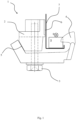
- Fig. 1 shows a clamping block 1 according to the state of the art, as described above in the technical background of the present disclosure.
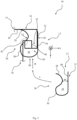
- Fig. 2 shows a system 10 for fastening an object 24 to an attachment structure 14 by an attachment clip 12.
- said system 10 comprises the attachment clip 12 and the attachment structure 14, said embodiment being illustrated by Fig. 2 in the manner of a sketch of its functional principle.
- Fig. 2 is therefore not showing any essential physical design and may be varied based on the outlined principles.
- the attachment structure 14 comprises an attachment channel 16.
- a channel in this context refers to any cross-sectional profile extending in a longitudinal direction x, said cross-sectional profile surrounding a certain area, but not being entirely closed.
- Said attachment channel 16 comprises an inner channel surface 18, which means a surface directed to the area surrounded by the cross-sectional profile of the attachment channel 16.
- the attachment channel 16 comprises a guiding portion 20 that is forming a guiding notch 22.
- the guiding portion 20 refers to the material of the attachment channel 16 that surrounds the guiding notch 22, the latter being an area free of material.
- Said guiding notch 22 is open towards the inner channel surface 18 and designed to guide an object 24 along said longitudinal direction x, if said object 24 is engaged with said guiding notch 22.
- said system 10 does not comprise said object 24 and is merely designed to be suitable for fastening an object 24, that may be added, to said attachment structure 14 by said attachment clip 12.
- the system 10 is also described in an embodiment wherein it comprises the object 24. Still, the following remains valid also for the basic embodiment of the system 10.
- the attachment clip 12 of the system 10 comprises a hook portion 26 with an upper hook portion 28 and a lower hook portion 30.
- the upper hook portion 28 and lower hook portion 30 are arranged in an S-type manner, which means they are curved in opposite directions and connected in an inflection point.
- the attachment clip 12 comprises a brake portion 32, wherein a cavity 34 is formed between said brake portion 32 and said hook portion 26.
- Said minimum distance 48 may vary in value, e.g. if the attachment clip 12 is elastically deformed. However, due to the S-type of shape of the hook portion 26, said minimum distance 48 always remains the smallest distance between the hook portion 26 and the brake portion 32.
- the attachment clip 12 is designed to be clipped onto said guiding portion 20. According to the design of the attachment clip 12 this can be achieved by moving, e.g. by handling, said cavity 34 transverse the longitudinal direction x to the guiding portion 20. This is illustrated by a step I in Fig. 2 .
- the guiding portion 20 snaps into said cavity 34 upon passing said upper hook portion 28, which means the guiding portion 20 passes the minimum distance 48.
- This causes partial reversal of said elastic deformation, because the guiding portion 20 does not spread apart the upper hook portion 28 and the brake portion 32 to the same extent anymore.
- the brake portion 32 and the hook portion 26 are pulled towards each other, which is indicated by a force 36 and a force 52 in Fig. 2 .
- the guiding portion 20 As the guiding portion 20 is now present in the cavity 34, it also causes the upper hook portion 28 to push onto said guiding portion 20 at a point, somewhere between the location of the minimum distance 48 and the lower hook portion 30. This is driven by the energy stored in the attachment clip 12 due to the elastic deformation, which is partially released upon partial reversal of said deformation. This pushing onto said guiding portion 20 causes the entire attachment clip 12, driven by said released energy, to be pushed upwards. This is indicated by force 50 in Fig. 2 . Upwards here means towards said guiding portion 20 and transverse said longitudinal direction x. Merely as an example, this corresponds to a negative direction z in Fig. 2 .
- the lower hook portion 30 may also push onto said guiding portion 20 and drive the attachment clip 12 upwards.
- said brake portion 32 is further pulled towards said hook portion 26 by the forces 36 and 52.
- the brake portion 32 applies the force 36 as a brake force to an outer surface 38 of the attachment structure 14.
- said upper hook portion 28 continues to be pushed against the inner channel surface 18, while being supported by the guiding portion 20 that serves as a counter bearing to force 52 in a section 42.
- the system 10 comprises the object 24.
- the object 24 has an insertion portion 40 that is engaged with the guiding notch 22 of the guiding portion 20 so that the object 24 may slide along the longitudinal direction x.
- the attachment clip 12 may be placed in front or behind the object 24 in longitudinal direction x. There may be more than one attachment clip 12, which means there could be an attachment clip 12 placed in front and behind the object 24, as well. Thus, the object 24 can be fastened totally in longitudinal direction x.
- the object 24 may comprise a recess that is not visible in Fig. 2 but indicated in section 42 (also compare Fig. 4 , ref. 43).
- the attachment clip 12 may extend through said recess, as indicated in section 42 by the interrupted line illustrating the attachment clip 12.
- the object 24 can be totally fastened in longitudinal direction x by a single attachment clip 12.
- the object 24 can be fastened totally in longitudinal direction x by a single attachment clip 12.
- steps I and II can be carried out directly.
- the insertion portion 40 of the object 24 may first be engaged with the guiding notch 22 of the guiding portion 20 and then the steps I and II may be carried out.
- the object 24 may be hung into the attachment channel 16 (into the guiding notch 22, respectively) or the object 24 may be slidden into the attachment channel 16 (into the guiding notch 22, respectively).
- Steps I and II may then be carried out by applying the attachment clip 12 to the guiding portion 20 via a recess in the object 24 or by placing the attachment clip 12 in front or behind the object 24.
- steps I and II first and then engage the insertion portion 40 of the object 24 with the guiding notch 22. Then, the object 24 may be slidden into the attachment channel 16, for example until it hits the attachment clip 12. If the attachment clip 12 shall be arranged in a recess of the object 24, however, the object 24 needs to be hung into the attachment channel 16, if steps I and II have been carried out first.
- the hook portion 26 and a brake portion 32 are spread apart, for example manually or by a simple tool, until the brake force 36 acting on the outer surface 38 has been reduced to a level allowing manual displacement of the attachment clip 12 along the longitudinal direction x.
- the attachment clip 12 is slidden off said guiding portion 20 along the longitudinal direction x. This may be done together with the object 24, which means the object 24 is slidden off the guiding notch 22 at the same time.
- the insertion portion 40 of said object 24 may be disengaged from said guiding notch 22 first, e.g. by sliding the object 24 off the guiding notch 22 or by unhinging the object 24 from the guiding notch 22.
- the system 10 is designed to fasten said object 24 in the longitudinal direction x so that it can stand an acceleration of at least 9G occurring in the longitudinal direction x, without displacement of said object 24 and the attachment clip 12, respectively.
- it is particularly suitable to be used in an aircraft.
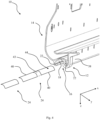
- Fig. 3 shows an embodiment of the attachment clip 12 that is particularly suitable to be used in an aircraft, but not limited to that.
- the attachment clip 12 in Fig. 3 is a single part, comprising the brake portion 32, the hook portion 26 and the cavity 34 therebetween.
- the brake portion 32 comprises a nose 54.
- the nose 54 may be accessed by hand or a tool to assemble or disassemble the attachment clip 12 in the system 10 (e.g. as shown in Fig. 2 or 4 ).
- the upper hook portion 28, the lower hook portion 30 and the brake portion 32 may comprise a material strength 56 of 1 mm to 3 mm, preferably 1,5 mm to 2,5 mm.
- the material strength may be 1 mm, 1,5 mm, 2 mm, 2,5 mm or 3 mm.
- the minimum distance 48 may range from once to twice the material strength 56, if the attachment clip 12 is not deformed.
- the minimum distance 48 may be once the material strength 56 or twice the material strength 56, if the attachment clip 12 is not deformed.
- Fig. 3 implies embodiments of the attachment clip 12 at true scale, but is not limited to that.
- Fig. 3 may be understood representing a true scale based on the above parameters material strength 56 and minimum distance 48.
- the attachment clip 12 is to be used in an aircraft, for example, in the case that typical PSUs shall be fastened by the system 10 in an aircraft.
- PSUs may feature a mass of 1 kg to 2kg, for example 1kg, 1,5 kg or 2kg.
- the attachment clip 12 of Fig. 3 or in other embodiments may be made of a plastic material, for example a thermoplastic material, such as "Ultem 9085".
- the attachment clip 12 may be manufactured by injection molding or extrusion.
- said brake portion 32 may comprise at least a section 46 that is surface treated or coated to enhance a coefficient of friction. In case of a coating, the attachment clip 12 may not be single part anymore.
- the section 46 of the brake portion 32 of the attachment clip 12 and/or the outer surface 38 of the attachment structure 14 are surface treated or coated to enhance friction between the brake portion 32 and the outer surface 38 in the context of the system 10.
- Fig. 4 shows a system 10 for fastening an object 24 to an attachment structure 14 by an attachment clip 12 in another embodiment. This embodiment may comprise the features described by Fig. 1 . Further, the system 10 in Fig. 4 comprises an attachment clip 12 as shown in Fig. 3 .
- the object 24 comprises an attachment portion 44 that is complementary to the attachment channel 16 and comprises the insertion portion 40.
- the object 24 is illustrated in a simplified manner by showing only the attachment portion 44.
- “Complementary” preferably implies that the shape of the attachment portion 44 essentially follows the contour of the inner channel surface 18, while the attachment portion 44 is inserted to the attachment channel 16 along the longitudinal direction x, whereby the insertion portion 40 slides along the guiding notch 22. This provides the advantage, that all degrees of freedom, except for movement in the longitudinal direction x, are disabled by the attachment channel 16. Thus, the object 24 can be safely positioned.
- attachment portion 44 fits into the space limited by the inner channel surface 18, but without disabling all those degrees of freedom.
- attachment channel 16 may comprise only one guiding notch 22 and the object 24 may comprise only one insertion portion 40 in other embodiments.
- said attachment channel 16 is designed in the manner of a slotted construction profile and the attachment portion 44 is designed in the manner of a corresponding slot-nut.
- the attachment channel 16 is designed in the manner of a T-slotted profile, also referred to as a T-slot structural framing, and the attachment portion 44 is designed in the manner of a T-slot-nut.
- Fig. 4 there are two objects 24 shown, merely as examples.
- One of those objects 24 has a recess 43, to which the attachment clip 12 can be introduced, once said object 24 has been slidden into the attachment channel 16.
- the recess 43 may be open or closed in the direction of the insertion portion 40, as indicated by the dash-dotted line.
- the other object 24 is illustrated without any recess. If such an object 24 without a recess is introduced to the attachment channel 16, the attachment clip 12 may be arranged in front or behind said object 24 (regarding the longitudinal direction x).
Landscapes
- Engineering & Computer Science (AREA)
- General Engineering & Computer Science (AREA)
- Mechanical Engineering (AREA)
- Aviation & Aerospace Engineering (AREA)
- Health & Medical Sciences (AREA)
- General Health & Medical Sciences (AREA)
- Pulmonology (AREA)
- Connection Of Plates (AREA)
Abstract
The present disclosure refers to a clamping block (12) in an aircraft that is used as a stop for passenger supply units (24) and oxygen containers, in a passenger supply channel (16) in flight direction (x). The clamping block (1) is made of plastic and features a single piece design. Installation can be done without the use of a tool by clicking the clamping block (1) onto the passenger supply channel (16) in an intended position.
The present disclosure further refers to a system (10) comprising the clamping block (12).
Description
- Generally, the present disclosure relates to systems for fastening an object to an attachment structure. More particularly, the present disclosure refers to systems comprising an attachment clip and an attachment structure for fastening an object to said attachment structure by said attachment clip.
- Various systems are known that serve the purpose of fastening an object to an attachment structure. In aviation for example, the cabin of an aircraft comprises devices to supply passengers with necessary functions, such as light, ventilation or oxygen in case of a loss of cabin pressure.
- Respective functional units may cover passenger supply/service units (PSUs) or oxygen containers, for example, that may be stored in a so-called passenger supply channel (PSC) of the aircraft. The PSC usually comprises a rail to receive the respective PSUs, for example by hanging in or sliding in the respective PSU to the PSC.
- However, during takeoff, flight and landing high acceleration forces may occur, exposing the PSUs to a risk of displacement on the rail. Therefore, it has been known to fasten the PSUs in position on the rail by means of a clamping block.
- With respect to
Fig. 1 , such a conventional clamping block 1 comprises abrake block 2, afastening screw 3 and afastening hook 4. Upon fastening of thefastening screw 3, thebrake block 2 will slide down aninclined surface 5 and thus abrake surface 6 will be pushed against arail 7. At the same time, thefastening hook 4 will, in a longitudinal direction 8 of therail 7, undercut a projection of aPSU 9 applied to therail 7. Thus, thePSU 9 is securely fastened on therail 7 the longitudinal direction 8. - Such clamping blocks consist of multiple parts that need to be manufactured and assembled and the overall effort is rather high. Assembly requires the use of additional tools, such as screw drivers. Due to the high mass of the respective parts. that are metal parts, the brake surface is relatively small, since the total mass is a critical design factor in aviation and limits the possible size of the clamping block.
- Based on that, it may be seen as an object of the present disclosure to suggest an alternative system for fastening an object to an attachment structure at low effort and low weight and at the same time at a high level of safety regarding the fastening function.
- A system, an attachment clip, an object to be attached, methods of assembling and disassembling the system, as well as an aircraft are provided, according to the features of the independent claims. Further embodiments are evident from the dependent claims and from the following description.
- A first aspect of the present disclosure refers to a system, comprising an attachment clip and an attachment structure. Said system is designed for fastening an object to said attachment structure by said attachment clip. The attachment structure comprises an attachment channel extending in a longitudinal direction. Said attachment channel comprises an inner channel surface and a guiding portion that is forming a guiding notch. Said guiding notch is open towards the inner channel surface and designed to guide an object along said longitudinal direction, if said object is engaged with said guiding notch. Further, the attachment clip comprises a hook portion with an upper hook portion and a lower hook portion in an S-type arrangement. The attachment clip further comprises a brake portion, wherein a cavity is formed between said brake portion and hook portion and said attachment clip is designed to be clipped onto said guiding portion by moving said cavity, transverse the longitudinal direction, to the guiding portion, wherein upon contacting said guiding portion the upper hook portion and the brake portion are spread apart under elastic deformation of the attachment clip. Further, said guiding portion is snapped into said cavity upon passing said upper hook portion under partial reversal of said elastic deformation, causing said upper hook portion to be pushed against the inner channel surface and said brake portion to be pulled towards said hook portion, thus applying a brake force to an outer surface of the attachment structure, while said upper hook portion is pushed against the inner channel surface and supported by the guiding portion.
- Preferably, the system comprises at least one object with an insertion portion designed to engage with the guiding notch of the guiding portion. Even further preferred, the insertion portion of the object is engaged with the guiding notch of the guiding portion and at least one attachment clip is fastened to the attachment structure. This means, said system is in an assembled state.
- The system of the present disclosure allows for easy and reliable fastening of an object to said attachment structure by said attachment clip, without requiring any tools. As elasticity of the attachment clip is exploited to achieve this, there are no additional parts required, such as screws or the like. This significantly reduces the effort to manufacture and handle such a system.
- The object of the system may be a PSU or an oxygen container of an aircraft, to be attached in a PSC as the attachment channel. Such PSUs or oxygen containers may feature a mass of 1kg or 2kg, for example.
- Preferably, said system is designed to fasten the object in the longitudinal direction, if an acceleration of at least 9G occurs in the longitudinal direction and pushes said object against said attachment clip, while said insertion portion of said object is engage with the guiding notch and said attachment clip is fastened to the attachment structure.
- The expected acceleration together with the masses, geometries and materials of the different components of the system are major parameters to be considered by the person skilled in the art, based upon which he is able to dimension the system for the expected accelerations. The acceleration may preferably be considered up to 9G to design the system of the present disclosure in the context of an aircraft. However, this does not limit applicability of the present disclosure and the acceleration could even be higher, e.g. 10G, 11G or 12G in other applications.
- Preferably, the attachment clip is a single part. Due to such a design, the brake portion is relatively larger regarding the overall size of the attachment clip, compared to the prior art. Preferably, the attachment clip is made of a plastic material, making it light in weight and less expensive than conventional metal solutions. The attachment clip may, for example, be manufactured by generative manufacturing, injection molding or extrusion. It may be manufactured in a continuous process, e.g. by extruding a continuous profile that can be cut into pieces to obtain single part attachment clips. These manufacturing methods also enable easy scalability of the attachment clip, for example by adapting a cut-off length of the extruded profile.
- The attachment clip can thus be manufactured at low effort and time and requires less material and costs.
- Preferably, said brake portion, at least in a section designed to apply the brake force to the outer surface of the attachment structure, is surface treated or coated to enhance friction on said outer surface. Alternatively, or in addition said outer surface may at least sectionally be surface treated or coated to enhance friction on the brake portion.
- Both said design options allow further reduction of the required size of the brake portion, because a coefficient of friction is increased.
- Preferably, the object comprises a recess, through which an attachment clip, fastened to the attachment structure, extends.
- Thus, the object can be safely fastened by a single attachment clip in positive and negative longitudinal direction.
- Also, an attachment clip may be fastened to the attachment structure along the longitudinal direction in front and/or behind said insertion portion.
- This allows for a flexible arrangement of the attachment clip according to the requirements of the object. Also, a plurality of attachment clips may be used to fasten one or more objects in the system of the present disclosure.
- Preferably, said object comprises an attachment portion that is complementary to said attachment channel and comprises the insertion portion. For example, said attachment channel may be designed in the manner of a slotted construction profile and the attachment portion may be designed in the manner of a corresponding slot-nut.
- This achieves a very comfortable and secure guidance of the object in the attachment channel.
- Another aspect of the present disclosure refers to an attachment clip, suitable for a system according to the present disclosure. Yet another aspect refers to an object, suitable for such a system.
- Another aspect of the present disclosure refers to a method of assembling a system according to the present disclosure. Said method comprises the following steps:
- Engaging an insertion portion of an object with a guiding notch of a guiding portion of an attachment channel, comprised by an attachment structure;
- Moving a cavity of an attachment clip, formed between a brake portion and a hook portion, transverse a longitudinal direction of said attachment channel to said guiding portion, wherein upon contacting said guiding portion, an upper hook portion of said hook portion and the brake portion are spread apart under elastic deformation of the attachment clip; and
- Snapping said guiding portion into said cavity, upon passing said upper hook portion, under partial reversal of said elastic deformation causing said upper hook portion to be pushed against an inner channel surface of said attachment channel and said brake portion to be pulled towards said hook portion, thus applying a brake force to an outer surface of the attachment structure, while said upper hook portion is pushed against the inner channel surface and supported by the guiding portion.
- Further, an aspect of the present disclosure refers to a method of disassembling a system according to the present disclosure that is in an assembled state. The method comprises the following steps:
- Spreading apart a hook portion and a brake portion of an attachment clip that is fastened to an attachment structure, until a brake force applied by the brake portion to an outer surface of said attachment structure has been reduced to a level allowing manual displacement of said attachment clip in a longitudinal direction along a guiding portion of said attachment channel; and
- Sliding said attachment clip off said guiding portion in the longitudinal direction, either together with an object fastened to said attachment structure by said attachment clip or under disengagement of an insertion portion of said object from said attachment structure prior to sliding off said attachment clip.
- Yet another aspect of the present disclosure refers to an aircraft, comprising a system according to the present disclosure.
- In other words, the subject matter of the present disclosure can be used in the passenger supply channel of an aircraft. The presented design is specifically created to fit passenger aircrafts. However, by adapting the design the present disclosure can be also used in other aircrafts or in the context of attachment tasks outside aviation. In an aircraft, conventional clamping blocks have been used as an "x-stop", for example to fasten PSUs or an oxygen container in x-direction of a PSC. These conventional clamping blocks are made from metal and consist of multiple small parts. All of them work by manually locking the part in place (e.g. with a screw) using a tool. The material of the present disclosure is preferably plastic, a lighter and less expensive material than the previously known solutions. Further, (de-) installation is greatly improved by the present disclosure. Installation can be done without the use of any tool, merely by clicking the clamping block in the intended position. Also, deinstallation is possible without any tools. The present disclosure relates to a clamping block made from a single piece of plastic material. By using the material elasticity and a specific design, the clamping block clicks into the intended position, without the need for a separate tool. To use this attachment principle, the material of the clamping block shall be elastic, preferably some kind of plastic material that stays in the elastic region while being (de-installed and also in its attached state. For the presented design, "Ultem 9085" can be used to withstand an acceleration of the aircraft of 9G. However, the present disclosure is not limited to this material. There may be a cut-out in the attachment system of the PSC component (e.g. PSU or oxygen container) through that the clamping block can be attached to the PSC. The surface of the system can (partly) be treated or coated to improve the resistance against displacement due to higher friction. As no tools are needed for (de-)installation, the present disclosure immensely simplifies installation of components in the PSC and reduces (de-)installation time and costs. Further the present disclosure refers to a clamping block consisting of one single plastic part, which can be (e.g.) injection molded or manufactured as a continuous extruded profile. This simplifies manufacturing processes. Material switch from metal to plastic further decreases production and part costs. Further, the material change from metal to plastic and the decreased part size/volume of the present disclosure, compared to the formerly known solutions, decreases the mass of the clamping block. The clamping block may be used to prevent PSC components from delocation. It is attached in a cut-out in the attachment interface of the component to be attached to the PSC and applies a force on the rail of the PSC. The force is generated by elastic deformation of the clamping block, as it is attached to the rail. For installation of the clamping block, it is pressed on the rail from below. Due to its material elasticity and its special design the clamping block clicks into position. During installation the deformation of the clamping block shall not exceed the material elasticity range, in order to maintain its shape and to ensure the clamping force. For deinstallation, the clamping block can be removed by sliding it off the rail. This may be done by temporarily changing the shape of the clamping block, for example by applying a force from the top or side, by pressing parts of the clamping block against the rail and/or by changing the angle between the clamping block and rail. The special design of the clamping block enables simple deinstallation.
- In short, the present disclosure refers to a clamping block in an aircraft that is used as a stop for passenger supply units and oxygen containers, in a passenger supply channel along the flight direction. The clamping block is made of plastic and features a single piece design. Installation can be done without the use of a tool by clicking the clamping block onto the passenger supply channel in an intended position. The present disclosure further refers to a system comprising the clamping block.
- The subject-matter of the present disclosure will hereinafter be described in conjunction with the following figures, wherein like numerals denote like elements, and wherein:
- Fig. 1
- shows a clamping block according to the state of the art;
- Fig. 2
- shows a system for fastening an object to an attachment structure by an attachment clip with reference to methods of assembling and disassembling said system;
- Fig. 3
- shows an embodiment of an attachment clip; and
- Fig. 4
- shows a system for fastening an object to an attachment structure by an attachment clip in another embodiment.
-
Fig. 1 shows a clamping block 1 according to the state of the art, as described above in the technical background of the present disclosure. -
Fig. 2 shows asystem 10 for fastening anobject 24 to anattachment structure 14 by anattachment clip 12. In a basic embodiment, saidsystem 10 comprises theattachment clip 12 and theattachment structure 14, said embodiment being illustrated byFig. 2 in the manner of a sketch of its functional principle. Apart from the physical structures described herein,Fig. 2 is therefore not showing any essential physical design and may be varied based on the outlined principles. - The
attachment structure 14 comprises anattachment channel 16. A channel in this context refers to any cross-sectional profile extending in a longitudinal direction x, said cross-sectional profile surrounding a certain area, but not being entirely closed. Saidattachment channel 16 comprises aninner channel surface 18, which means a surface directed to the area surrounded by the cross-sectional profile of theattachment channel 16. Further, theattachment channel 16 comprises a guidingportion 20 that is forming a guidingnotch 22. The guidingportion 20 refers to the material of theattachment channel 16 that surrounds the guidingnotch 22, the latter being an area free of material. Said guidingnotch 22 is open towards theinner channel surface 18 and designed to guide anobject 24 along said longitudinal direction x, if saidobject 24 is engaged with said guidingnotch 22. - In the basic embodiment, said
system 10 does not comprise saidobject 24 and is merely designed to be suitable for fastening anobject 24, that may be added, to saidattachment structure 14 by saidattachment clip 12. However, in the following thesystem 10 is also described in an embodiment wherein it comprises theobject 24. Still, the following remains valid also for the basic embodiment of thesystem 10. - The
attachment clip 12 of thesystem 10 comprises ahook portion 26 with anupper hook portion 28 and alower hook portion 30. Theupper hook portion 28 andlower hook portion 30 are arranged in an S-type manner, which means they are curved in opposite directions and connected in an inflection point. Further, theattachment clip 12 comprises abrake portion 32, wherein acavity 34 is formed between saidbrake portion 32 and saidhook portion 26. As a consequence of saidupper hook portion 28 andlower hook portion 30 being arranged in an S-type manner, there is aminimum distance 48 between saidupper hook portion 28 and saidbrake portion 32. Saidminimum distance 48 may vary in value, e.g. if theattachment clip 12 is elastically deformed. However, due to the S-type of shape of thehook portion 26, saidminimum distance 48 always remains the smallest distance between thehook portion 26 and thebrake portion 32. - The
attachment clip 12 is designed to be clipped onto said guidingportion 20. According to the design of theattachment clip 12 this can be achieved by moving, e.g. by handling, saidcavity 34 transverse the longitudinal direction x to the guidingportion 20. This is illustrated by a step I inFig. 2 . - Upon contacting said guiding
portion 20, which means when the guidingportion 20 contacts theupper hook portion 28 and thebrake portion 32 due to said movement, theupper hook portion 28 and thebrake portion 32 are spread apart under elastic deformation of theattachment clip 12. This is due to the force applied by the guidingportion 20 to theupper hook portion 28 and thebrake portion 32, as a consequence of the movement. - Then (illustrated in
Fig. 2 as a step II), the guidingportion 20 snaps into saidcavity 34 upon passing saidupper hook portion 28, which means the guidingportion 20 passes theminimum distance 48. This causes partial reversal of said elastic deformation, because the guidingportion 20 does not spread apart theupper hook portion 28 and thebrake portion 32 to the same extent anymore. In other words, thebrake portion 32 and thehook portion 26 are pulled towards each other, which is indicated by aforce 36 and aforce 52 inFig. 2 . - As the guiding
portion 20 is now present in thecavity 34, it also causes theupper hook portion 28 to push onto said guidingportion 20 at a point, somewhere between the location of theminimum distance 48 and thelower hook portion 30. This is driven by the energy stored in theattachment clip 12 due to the elastic deformation, which is partially released upon partial reversal of said deformation. This pushing onto said guidingportion 20 causes theentire attachment clip 12, driven by said released energy, to be pushed upwards. This is indicated byforce 50 inFig. 2 . Upwards here means towards said guidingportion 20 and transverse said longitudinal direction x. Merely as an example, this corresponds to a negative direction z inFig. 2 . - It shall be understood, that depending on a specific geometry of the guiding
portion 20 and thehook portion 26, which may vary in different embodiments, thelower hook portion 30 may also push onto said guidingportion 20 and drive theattachment clip 12 upwards. - The described effect of said
attachment clip 12 being pushed upwards further causes saidupper hook portion 28 to contact theinner channel surface 18 and to be pushed against it. Thus, saidattachment clip 12 has found its final position transverse said longitudinal direction x on theattachment channel 16. - As the elastic deformation is only reversed partially, said
brake portion 32 is further pulled towards saidhook portion 26 by theforces brake portion 32 applies theforce 36 as a brake force to anouter surface 38 of theattachment structure 14. At the same time, saidupper hook portion 28 continues to be pushed against theinner channel surface 18, while being supported by the guidingportion 20 that serves as a counter bearing to force 52 in asection 42. - In this embodiment, the
system 10 comprises theobject 24. Theobject 24 has aninsertion portion 40 that is engaged with the guidingnotch 22 of the guidingportion 20 so that theobject 24 may slide along the longitudinal direction x. - However, as can be seen in
section 42, projections of theattachment clip 12 and theobject 24 along the longitudinal direction x are overlapping. This means, saidattachment clip 12 is forming a conflicting contour, if saidobject 24 attempts to slide along the longitudinal direction x and hits saidattachment clip 12. Thus, theattachment clip 12 fastens saidobject 24 to theattachment structure 14 in the longitudinal direction x. - The
attachment clip 12 may be placed in front or behind theobject 24 in longitudinal direction x. There may be more than oneattachment clip 12, which means there could be anattachment clip 12 placed in front and behind theobject 24, as well. Thus, theobject 24 can be fastened totally in longitudinal direction x. - Preferably, the
object 24 may comprise a recess that is not visible inFig. 2 but indicated in section 42 (also compareFig. 4 , ref. 43). Theattachment clip 12 may extend through said recess, as indicated insection 42 by the interrupted line illustrating theattachment clip 12. Thus, theobject 24 can be totally fastened in longitudinal direction x by asingle attachment clip 12. Thus, theobject 24 can be fastened totally in longitudinal direction x by asingle attachment clip 12. - With reference to methods of assembling and disassembling said
system 10, the above configurations may be achieved as follows:
To assemble thesystem 10 in the basic embodiment, steps I and II can be carried out directly. - In embodiments wherein the
object 24 is comprised by thesystem 10, theinsertion portion 40 of theobject 24 may first be engaged with the guidingnotch 22 of the guidingportion 20 and then the steps I and II may be carried out. Theobject 24 may be hung into the attachment channel 16 (into the guidingnotch 22, respectively) or theobject 24 may be slidden into the attachment channel 16 (into the guidingnotch 22, respectively). Steps I and II may then be carried out by applying theattachment clip 12 to the guidingportion 20 via a recess in theobject 24 or by placing theattachment clip 12 in front or behind theobject 24. - It is also possible to carry out steps I and II first and then engage the
insertion portion 40 of theobject 24 with the guidingnotch 22. Then, theobject 24 may be slidden into theattachment channel 16, for example until it hits theattachment clip 12. If theattachment clip 12 shall be arranged in a recess of theobject 24, however, theobject 24 needs to be hung into theattachment channel 16, if steps I and II have been carried out first. - To disassemble the
system 10, thehook portion 26 and abrake portion 32 are spread apart, for example manually or by a simple tool, until thebrake force 36 acting on theouter surface 38 has been reduced to a level allowing manual displacement of theattachment clip 12 along the longitudinal direction x. - Then, the
attachment clip 12 is slidden off said guidingportion 20 along the longitudinal direction x. This may be done together with theobject 24, which means theobject 24 is slidden off the guidingnotch 22 at the same time. Alternatively, theinsertion portion 40 of saidobject 24 may be disengaged from said guidingnotch 22 first, e.g. by sliding theobject 24 off the guidingnotch 22 or by unhinging theobject 24 from the guidingnotch 22. - Preferably, the
system 10 is designed to fasten saidobject 24 in the longitudinal direction x so that it can stand an acceleration of at least 9G occurring in the longitudinal direction x, without displacement of saidobject 24 and theattachment clip 12, respectively. Thus, it is particularly suitable to be used in an aircraft. -
Fig. 3 shows an embodiment of theattachment clip 12 that is particularly suitable to be used in an aircraft, but not limited to that. - The
attachment clip 12 inFig. 3 is a single part, comprising thebrake portion 32, thehook portion 26 and thecavity 34 therebetween. For improved handling, thebrake portion 32 comprises anose 54. Thenose 54 may be accessed by hand or a tool to assemble or disassemble theattachment clip 12 in the system 10 (e.g. as shown inFig. 2 or4 ). - The
upper hook portion 28, thelower hook portion 30 and the brake portion 32 (but not necessarily the nose 54) may comprise amaterial strength 56 of 1 mm to 3 mm, preferably 1,5 mm to 2,5 mm. For example, the material strength may be 1 mm, 1,5 mm, 2 mm, 2,5 mm or 3 mm. Theminimum distance 48 may range from once to twice thematerial strength 56, if theattachment clip 12 is not deformed. For example, theminimum distance 48 may be once thematerial strength 56 or twice thematerial strength 56, if theattachment clip 12 is not deformed. -
Fig. 3 implies embodiments of theattachment clip 12 at true scale, but is not limited to that. In particular,Fig. 3 may be understood representing a true scale based on the aboveparameters material strength 56 andminimum distance 48. - Experiments have shown that the above parameters are particularly beneficial, if the
attachment clip 12 is to be used in an aircraft, for example, in the case that typical PSUs shall be fastened by thesystem 10 in an aircraft. Such PSUs may feature a mass of 1 kg to 2kg, for example 1kg, 1,5 kg or 2kg. - The
attachment clip 12 ofFig. 3 or in other embodiments may be made of a plastic material, for example a thermoplastic material, such as "Ultem 9085". Theattachment clip 12 may be manufactured by injection molding or extrusion. - To design the
attachment clip 12 to resist high acceleration in thesystem 10, saidbrake portion 32 may comprise at least asection 46 that is surface treated or coated to enhance a coefficient of friction. In case of a coating, theattachment clip 12 may not be single part anymore. - It is also possible to, at least sectionally, surface treat or coat the
outer surface 38 of the attachment structure 14 (compareFigs. 2 and4 ) to enhance a coefficient of friction, which is further described with reference toFig. 4 . - Preferably, the
section 46 of thebrake portion 32 of theattachment clip 12 and/or theouter surface 38 of theattachment structure 14 are surface treated or coated to enhance friction between thebrake portion 32 and theouter surface 38 in the context of thesystem 10. -
Fig. 4 shows asystem 10 for fastening anobject 24 to anattachment structure 14 by anattachment clip 12 in another embodiment. This embodiment may comprise the features described byFig. 1 . Further, thesystem 10 inFig. 4 comprises anattachment clip 12 as shown inFig. 3 . - As can be seen in
Fig. 4 , theobject 24 comprises anattachment portion 44 that is complementary to theattachment channel 16 and comprises theinsertion portion 40. InFig. 4 , theobject 24 is illustrated in a simplified manner by showing only theattachment portion 44. - "Complementary" preferably implies that the shape of the
attachment portion 44 essentially follows the contour of theinner channel surface 18, while theattachment portion 44 is inserted to theattachment channel 16 along the longitudinal direction x, whereby theinsertion portion 40 slides along the guidingnotch 22. This provides the advantage, that all degrees of freedom, except for movement in the longitudinal direction x, are disabled by theattachment channel 16. Thus, theobject 24 can be safely positioned. - However, in other embodiments "complementary" may merely imply that the
attachment portion 44 fits into the space limited by theinner channel surface 18, but without disabling all those degrees of freedom. Further, theattachment channel 16 may comprise only one guidingnotch 22 and theobject 24 may comprise only oneinsertion portion 40 in other embodiments. - Turing back to the embodiment illustrated in
Fig. 4 , saidattachment channel 16 is designed in the manner of a slotted construction profile and theattachment portion 44 is designed in the manner of a corresponding slot-nut. In this example, theattachment channel 16 is designed in the manner of a T-slotted profile, also referred to as a T-slot structural framing, and theattachment portion 44 is designed in the manner of a T-slot-nut. - In
Fig. 4 , there are twoobjects 24 shown, merely as examples. One of thoseobjects 24 has arecess 43, to which theattachment clip 12 can be introduced, once saidobject 24 has been slidden into theattachment channel 16. Therecess 43 may be open or closed in the direction of theinsertion portion 40, as indicated by the dash-dotted line. Theother object 24 is illustrated without any recess. If such anobject 24 without a recess is introduced to theattachment channel 16, theattachment clip 12 may be arranged in front or behind said object 24 (regarding the longitudinal direction x). -
- 10
- system
- 12
- attachment clip
- 14
- attachment structure
- 16
- attachment channel
- 18
- inner channel surface
- 20
- guiding portion
- 22
- guiding notch
- 24
- object
- 26
- hook portion
- 28
- upper hook portion
- 30
- lower hook portion
- 32
- brake portion
- 34
- cavity
- 36
- force
- 38
- outer surface
- 40
- insertion portion
- 42
- recess
- 44
- attachment portion
- 46
- section
- 48
- minimum distance
- 50
- force
- 52
- force
- 54
- nose
- 56
- material strength
- x
- longitudinal direction
- I
- step
- II
- step
Claims (15)
- System (10), comprising an attachment clip (12) and an attachment structure (14), said system (10) being designed for fastening an object (24) to said attachment structure (14) by said attachment clip (12), wherein:- the attachment structure (14) comprises an attachment channel (16) extending in a longitudinal direction (x), said attachment channel (16) comprising an inner channel surface (18) and a guiding portion (20) that is forming a guiding notch (22), said guiding notch (22) being open towards the inner channel surface (18) and designed to guide an object (24) along said longitudinal direction (x), if said object (24) is engaged with said guiding notch (22); and- the attachment clip (12) comprises a hook portion (26) with an upper hook portion (28) and a lower hook portion (30) in an S-type arrangement, and further comprises a brake portion (32), wherein a cavity (34) is formed between said brake portion (32) and hook portion (26) and said attachment clip (12) is designed to be clipped onto said guiding portion (20) by:- moving said cavity (34), transverse the longitudinal direction (x), to the guiding portion (20), wherein upon contacting said guiding portion (20) the upper hook portion (28) and the brake portion (32) are spread apart under elastic deformation of the attachment clip (12); and- snapping said guiding portion (20) into said cavity (34) upon passing said upper hook portion (28) under partial reversal of said elastic deformation, causing said upper hook portion (28) to be pushed against the inner channel surface (18) and said brake portion (32) to be pulled towards said hook portion (26), thus applying a brake force (36) to an outer surface (38) of the attachment structure (14), while said upper hook portion (28) is pushed against the inner channel surface (18) and supported by the guiding portion (20).
- System (10) according to claim 1, comprising at least one object (24) with an insertion portion (40) designed to engage with the guiding notch (22) of the guiding portion (20).
- System (10) according to claim 2, wherein the insertion portion (40) of the object (24) is engaged with the guiding notch (22) of the guiding portion (20) and at least one attachment clip (12) is fastened to the attachment structure (14).
- System (10) according to claim 3, wherein the object (24) comprises a recess (42), through which an attachment clip (12), fastened to the attachment structure (14), extends.
- System (10) according to claim 3 or 4, wherein, along the longitudinal direction (x), an attachment clip (12) is fastened to the attachment structure (14) in front and/or behind said insertion portion (40).
- System (10) according to any of the preceding claims, wherein said object (24) comprises an attachment portion (44) that is complementary to said attachment channel (16) and comprises the insertion portion (40).
- System (10) according to claim 6, wherein said attachment channel (16) is designed in the manner of a slotted construction profile and the attachment portion (44) is designed in the manner of a corresponding slot-nut.
- System (10) according to any of the preceding claims, wherein the attachment clip (12) is a single part.
- System (10) according to any of the preceding claims, wherein said brake portion (32), at least in a section (46) designed to apply the brake force (36) to the outer surface (38) of the attachment structure (14), is surface treated or coated to enhance friction on said outer surface (38) and/or said outer surface (38) is at least sectionally surface treated or coated to enhance friction on the brake portion (32).
- System (10) according to any of the claims 2 to 9, said system (10) being designed to fasten said object (24) in the longitudinal direction (x), if an acceleration of at least 9G occurs in the longitudinal direction (x) and pushes said object (24) against said attachment clip (12), while said insertion portion (40) of said object (24) is engage with the guiding notch (22) and said attachment clip (12) is fastened to the attachment structure (14).
- Attachment clip (12), suitable for a system (10) according to any of the preceding claims.
- Object (24), suitable for a system (10) according to any of the claims 1 to 10.
- Method of assembling a system (10) according to any of the claims 3 to 10, comprising the following steps:- Engaging an insertion portion (40) of an object (24) with a guiding notch (22) of a guiding portion (20) of an attachment channel (16), comprised by an attachment structure (14);- Moving a cavity (34) of an attachment clip (12), formed between a brake portion (32) and a hook portion (26), transverse a longitudinal direction (x) of said attachment channel (16) to said guiding portion (20), wherein upon contacting said guiding portion (20), an upper hook portion (28) of said hook portion (26) and the brake portion (32) are spread apart under elastic deformation of the attachment clip (12); and- Snapping said guiding portion (20) into said cavity (34), upon passing said upper hook portion (28), under partial reversal of said elastic deformation causing said upper hook portion (28) to be pushed against an inner channel surface (18) of said attachment channel (16) and said brake portion (32) to be pulled towards said hook portion (26), thus applying a brake force (36) to an outer surface (38) of the attachment structure (14), while said upper hook portion (28) is pushed against the inner channel surface (18) and supported by the guiding portion (20).
- Method of disassembling a system (10) according to any of the claims 3 to 10, comprising the following steps:- Spreading apart a hook portion (26) and a brake portion (32) of an attachment clip (12) that is fastened to an attachment structure (14), until a brake force (36) applied by the brake portion (32) to an outer surface (38) of said attachment structure (14) has been reduced to a level allowing manual displacement of said attachment clip (12) in a longitudinal direction (x) along a guiding portion (20) of said attachment channel (16); and- Sliding said attachment clip (12) off said guiding portion (20) in the longitudinal direction (x), either together with an object (24) fastened to said attachment structure (14) by said attachment clip (12) or under disengagement of an insertion portion (40) of said object (24) from said attachment structure (14) prior to sliding off said attachment clip (12).
- Aircraft, comprising a system (10) according to any of the claims 1 to 10.
Priority Applications (2)
| Application Number | Priority Date | Filing Date | Title |
|---|---|---|---|
| EP23205961.8A EP4545810A1 (en) | 2023-10-26 | 2023-10-26 | Attachment clip for fastening an object on a rail |
| US18/924,641 US20250136279A1 (en) | 2023-10-26 | 2024-10-23 | Attachment clip for fastening an object on a rail |
Applications Claiming Priority (1)
| Application Number | Priority Date | Filing Date | Title |
|---|---|---|---|
| EP23205961.8A EP4545810A1 (en) | 2023-10-26 | 2023-10-26 | Attachment clip for fastening an object on a rail |
Publications (1)
| Publication Number | Publication Date |
|---|---|
| EP4545810A1 true EP4545810A1 (en) | 2025-04-30 |
Family
ID=88558412
Family Applications (1)
| Application Number | Title | Priority Date | Filing Date |
|---|---|---|---|
| EP23205961.8A Pending EP4545810A1 (en) | 2023-10-26 | 2023-10-26 | Attachment clip for fastening an object on a rail |
Country Status (2)
| Country | Link |
|---|---|
| US (1) | US20250136279A1 (en) |
| EP (1) | EP4545810A1 (en) |
Citations (7)
| Publication number | Priority date | Publication date | Assignee | Title |
|---|---|---|---|---|
| FR2437521A1 (en) * | 1978-09-27 | 1980-04-25 | Renault | DOUBLE CLAMP |
| DE19952155A1 (en) * | 1999-10-29 | 2001-05-03 | Volkswagen Ag | Cable, pipe or wire fastening clip for use in road vehicle has L-shaped bracket holding U-section clip member with curved arm defining space for cable |
| EP1710111B1 (en) * | 2003-11-26 | 2008-09-03 | Coba Plastics Limited | A flexible strip and a method of manufacturing same |
| US10081305B2 (en) * | 2014-04-04 | 2018-09-25 | Jaguar Land Rover Limited | Accessory mounting system for vehicle load space |
| EP2757271B1 (en) * | 2013-01-22 | 2021-02-24 | Steven Tiller | A clip |
| US20210347462A1 (en) * | 2020-05-08 | 2021-11-11 | Premium Aerotec Gmbh | Connector And Method For Connecting A Frame And A Stringer Of A Fuselage Structure Of An Aircraft, Fuselage Structure And Aircraft |
| US11236858B1 (en) * | 2019-09-24 | 2022-02-01 | Charles E. Rigby | Strut channel mounting bracket |
Family Cites Families (3)
| Publication number | Priority date | Publication date | Assignee | Title |
|---|---|---|---|---|
| US4384605A (en) * | 1981-08-18 | 1983-05-24 | Cooper Industries, Inc. | Valance support for headrail |
| US5720398A (en) * | 1996-09-04 | 1998-02-24 | Fasteners For Retail, Inc. | Power wing clip |
| WO2019123466A1 (en) * | 2017-12-20 | 2019-06-27 | G.M Afcon Security Technologies Limited Partnership | Remote deployment of a device |
-
2023
- 2023-10-26 EP EP23205961.8A patent/EP4545810A1/en active Pending
-
2024
- 2024-10-23 US US18/924,641 patent/US20250136279A1/en active Pending
Patent Citations (7)
| Publication number | Priority date | Publication date | Assignee | Title |
|---|---|---|---|---|
| FR2437521A1 (en) * | 1978-09-27 | 1980-04-25 | Renault | DOUBLE CLAMP |
| DE19952155A1 (en) * | 1999-10-29 | 2001-05-03 | Volkswagen Ag | Cable, pipe or wire fastening clip for use in road vehicle has L-shaped bracket holding U-section clip member with curved arm defining space for cable |
| EP1710111B1 (en) * | 2003-11-26 | 2008-09-03 | Coba Plastics Limited | A flexible strip and a method of manufacturing same |
| EP2757271B1 (en) * | 2013-01-22 | 2021-02-24 | Steven Tiller | A clip |
| US10081305B2 (en) * | 2014-04-04 | 2018-09-25 | Jaguar Land Rover Limited | Accessory mounting system for vehicle load space |
| US11236858B1 (en) * | 2019-09-24 | 2022-02-01 | Charles E. Rigby | Strut channel mounting bracket |
| US20210347462A1 (en) * | 2020-05-08 | 2021-11-11 | Premium Aerotec Gmbh | Connector And Method For Connecting A Frame And A Stringer Of A Fuselage Structure Of An Aircraft, Fuselage Structure And Aircraft |
Also Published As
| Publication number | Publication date |
|---|---|
| US20250136279A1 (en) | 2025-05-01 |
Similar Documents
| Publication | Publication Date | Title |
|---|---|---|
| EP0403192B1 (en) | Adhesive mounted nutplate assembly | |
| EP1780120A3 (en) | Methods and systems for manufacturing a family of aircraft wings and other composite structures | |
| EP3104026B1 (en) | Plastic lining fasteners | |
| US20120240362A1 (en) | Inertia Locking Hidden Pushpin | |
| EP3501994B1 (en) | Aircraft and method for producing an aircraft | |
| EP3101307A1 (en) | Interference arrangement for spring | |
| US4877362A (en) | Sheathed composite blind rivet | |
| EP2560876B1 (en) | Tray table stop assembly | |
| US20250136279A1 (en) | Attachment clip for fastening an object on a rail | |
| US6814331B2 (en) | Device for removably fastening a first part to a second part mountable in an aircraft | |
| EP3446847A1 (en) | Member for temporarily holding component, and component attachment tool | |
| EP4253227B1 (en) | Quick-release wing structure and an unmanned aerial vehicle using the same | |
| CN119301376A (en) | fastener | |
| CN109963780A (en) | Window with emergency exit function of helicopter and method of removing transparent element from the window | |
| EP1924777A1 (en) | Device and method for mounting objects on a vehicle wall | |
| US20090071273A1 (en) | Device for controlling motion | |
| WO1994022154A1 (en) | Panel mount switch assembly | |
| US9637219B2 (en) | Fairing transition and vehicle with a movable body and a fixed body comprising a fairing transition | |
| EP3835601B1 (en) | A releasable fastening device and a method for operating a releasable fastening device | |
| EP0744555A1 (en) | Adhesive mounted nutplate assembly | |
| US11806950B2 (en) | Mold assembly for manufacturing a composite part with a stiffener, method of manufacturing a composite part and composite part with a stiffener | |
| CN107264770B (en) | Sidewall mounting hardware for aircraft | |
| US10415747B1 (en) | Brackets and assemblies for attaching objects to surfaces in vehicles | |
| GB2586495A (en) | Gap Filler | |
| US12330793B2 (en) | Method for translating pins using a rotary actuator |
Legal Events
| Date | Code | Title | Description |
|---|---|---|---|
| PUAI | Public reference made under article 153(3) epc to a published international application that has entered the european phase |
Free format text: ORIGINAL CODE: 0009012 |
|
| STAA | Information on the status of an ep patent application or granted ep patent |
Free format text: STATUS: THE APPLICATION HAS BEEN PUBLISHED |
|
| AK | Designated contracting states |
Kind code of ref document: A1 Designated state(s): AL AT BE BG CH CY CZ DE DK EE ES FI FR GB GR HR HU IE IS IT LI LT LU LV MC ME MK MT NL NO PL PT RO RS SE SI SK SM TR |
|
| STAA | Information on the status of an ep patent application or granted ep patent |
Free format text: STATUS: REQUEST FOR EXAMINATION WAS MADE |
|
| 17P | Request for examination filed |
Effective date: 20251030 |