EP4545800A1 - Blade and axial impeller using same - Google Patents
Blade and axial impeller using same Download PDFInfo
- Publication number
- EP4545800A1 EP4545800A1 EP23829922.6A EP23829922A EP4545800A1 EP 4545800 A1 EP4545800 A1 EP 4545800A1 EP 23829922 A EP23829922 A EP 23829922A EP 4545800 A1 EP4545800 A1 EP 4545800A1
- Authority
- EP
- European Patent Office
- Prior art keywords
- blade
- angle
- axial
- rotation axis
- leading edge
- Prior art date
- Legal status (The legal status is an assumption and is not a legal conclusion. Google has not performed a legal analysis and makes no representation as to the accuracy of the status listed.)
- Pending
Links
Images



Classifications
-
- F—MECHANICAL ENGINEERING; LIGHTING; HEATING; WEAPONS; BLASTING
- F04—POSITIVE - DISPLACEMENT MACHINES FOR LIQUIDS; PUMPS FOR LIQUIDS OR ELASTIC FLUIDS
- F04D—NON-POSITIVE-DISPLACEMENT PUMPS
- F04D29/00—Details, component parts, or accessories
- F04D29/26—Rotors specially for elastic fluids
- F04D29/32—Rotors specially for elastic fluids for axial flow pumps
- F04D29/38—Blades
- F04D29/384—Blades characterised by form
- F04D29/386—Skewed blades
-
- F—MECHANICAL ENGINEERING; LIGHTING; HEATING; WEAPONS; BLASTING
- F04—POSITIVE - DISPLACEMENT MACHINES FOR LIQUIDS; PUMPS FOR LIQUIDS OR ELASTIC FLUIDS
- F04D—NON-POSITIVE-DISPLACEMENT PUMPS
- F04D29/00—Details, component parts, or accessories
- F04D29/26—Rotors specially for elastic fluids
- F04D29/32—Rotors specially for elastic fluids for axial flow pumps
- F04D29/38—Blades
- F04D29/384—Blades characterised by form
-
- F—MECHANICAL ENGINEERING; LIGHTING; HEATING; WEAPONS; BLASTING
- F04—POSITIVE - DISPLACEMENT MACHINES FOR LIQUIDS; PUMPS FOR LIQUIDS OR ELASTIC FLUIDS
- F04D—NON-POSITIVE-DISPLACEMENT PUMPS
- F04D29/00—Details, component parts, or accessories
- F04D29/26—Rotors specially for elastic fluids
- F04D29/32—Rotors specially for elastic fluids for axial flow pumps
- F04D29/321—Rotors specially for elastic fluids for axial flow pumps for axial flow compressors
-
- F—MECHANICAL ENGINEERING; LIGHTING; HEATING; WEAPONS; BLASTING
- F04—POSITIVE - DISPLACEMENT MACHINES FOR LIQUIDS; PUMPS FOR LIQUIDS OR ELASTIC FLUIDS
- F04D—NON-POSITIVE-DISPLACEMENT PUMPS
- F04D29/00—Details, component parts, or accessories
- F04D29/26—Rotors specially for elastic fluids
- F04D29/32—Rotors specially for elastic fluids for axial flow pumps
- F04D29/321—Rotors specially for elastic fluids for axial flow pumps for axial flow compressors
- F04D29/324—Blades
-
- F—MECHANICAL ENGINEERING; LIGHTING; HEATING; WEAPONS; BLASTING
- F04—POSITIVE - DISPLACEMENT MACHINES FOR LIQUIDS; PUMPS FOR LIQUIDS OR ELASTIC FLUIDS
- F04D—NON-POSITIVE-DISPLACEMENT PUMPS
- F04D29/00—Details, component parts, or accessories
- F04D29/26—Rotors specially for elastic fluids
- F04D29/32—Rotors specially for elastic fluids for axial flow pumps
- F04D29/325—Rotors specially for elastic fluids for axial flow pumps for axial flow fans
-
- F—MECHANICAL ENGINEERING; LIGHTING; HEATING; WEAPONS; BLASTING
- F04—POSITIVE - DISPLACEMENT MACHINES FOR LIQUIDS; PUMPS FOR LIQUIDS OR ELASTIC FLUIDS
- F04D—NON-POSITIVE-DISPLACEMENT PUMPS
- F04D29/00—Details, component parts, or accessories
- F04D29/66—Combating cavitation, whirls, noise, vibration or the like; Balancing
-
- F—MECHANICAL ENGINEERING; LIGHTING; HEATING; WEAPONS; BLASTING
- F04—POSITIVE - DISPLACEMENT MACHINES FOR LIQUIDS; PUMPS FOR LIQUIDS OR ELASTIC FLUIDS
- F04D—NON-POSITIVE-DISPLACEMENT PUMPS
- F04D29/00—Details, component parts, or accessories
- F04D29/66—Combating cavitation, whirls, noise, vibration or the like; Balancing
- F04D29/661—Combating cavitation, whirls, noise, vibration or the like; Balancing especially adapted for elastic fluid pumps
- F04D29/666—Combating cavitation, whirls, noise, vibration or the like; Balancing especially adapted for elastic fluid pumps by means of rotor construction or layout, e.g. unequal distribution of blades or vanes
-
- F—MECHANICAL ENGINEERING; LIGHTING; HEATING; WEAPONS; BLASTING
- F05—INDEXING SCHEMES RELATING TO ENGINES OR PUMPS IN VARIOUS SUBCLASSES OF CLASSES F01-F04
- F05D—INDEXING SCHEME FOR ASPECTS RELATING TO NON-POSITIVE-DISPLACEMENT MACHINES OR ENGINES, GAS-TURBINES OR JET-PROPULSION PLANTS
- F05D2240/00—Components
- F05D2240/20—Rotors
- F05D2240/30—Characteristics of rotor blades, i.e. of any element transforming dynamic fluid energy to or from rotational energy and being attached to a rotor
- F05D2240/303—Characteristics of rotor blades, i.e. of any element transforming dynamic fluid energy to or from rotational energy and being attached to a rotor related to the leading edge of a rotor blade
-
- F—MECHANICAL ENGINEERING; LIGHTING; HEATING; WEAPONS; BLASTING
- F05—INDEXING SCHEMES RELATING TO ENGINES OR PUMPS IN VARIOUS SUBCLASSES OF CLASSES F01-F04
- F05D—INDEXING SCHEME FOR ASPECTS RELATING TO NON-POSITIVE-DISPLACEMENT MACHINES OR ENGINES, GAS-TURBINES OR JET-PROPULSION PLANTS
- F05D2240/00—Components
- F05D2240/20—Rotors
- F05D2240/30—Characteristics of rotor blades, i.e. of any element transforming dynamic fluid energy to or from rotational energy and being attached to a rotor
- F05D2240/304—Characteristics of rotor blades, i.e. of any element transforming dynamic fluid energy to or from rotational energy and being attached to a rotor related to the trailing edge of a rotor blade
-
- Y—GENERAL TAGGING OF NEW TECHNOLOGICAL DEVELOPMENTS; GENERAL TAGGING OF CROSS-SECTIONAL TECHNOLOGIES SPANNING OVER SEVERAL SECTIONS OF THE IPC; TECHNICAL SUBJECTS COVERED BY FORMER USPC CROSS-REFERENCE ART COLLECTIONS [XRACs] AND DIGESTS
- Y02—TECHNOLOGIES OR APPLICATIONS FOR MITIGATION OR ADAPTATION AGAINST CLIMATE CHANGE
- Y02E—REDUCTION OF GREENHOUSE GAS [GHG] EMISSIONS, RELATED TO ENERGY GENERATION, TRANSMISSION OR DISTRIBUTION
- Y02E10/00—Energy generation through renewable energy sources
- Y02E10/70—Wind energy
- Y02E10/72—Wind turbines with rotation axis in wind direction
Definitions
- the present application relates to the field of rotating machinery such as fans, pumps and compressors, and more particularly to a blade and an axial-flow impeller using the same.
- a leading edge and a trailing edge of a traditional blade are usually monotonous smooth curves. Since serious flow separation on the surface of the blade induces a vortex, a loud noise is produced.
- the present application provides a blade, comprising a blade tip, a blade root, a leading edge and a trailing edge, wherein the leading edge and the trailing edge extend from the blade tip to the blade root, respectively, and the blade is capable of rotating about a rotation axis X which is perpendicular to a normal plane.
- a circumferential included angle between the leading edge and the trailing edge forms a wrap angle ⁇
- the wrap angle ⁇ decreases gradually from the blade root to a middle blade height of the blade and increases gradually from the middle blade height to the blade tip, wherein the middle blade height is an arc line formed by center points of the blade tip and the blade root along a radial direction.
- the rotation axis X and the normal plane intersect perpendicularly at a foot of a perpendicular O.
- a line connecting any point on the leading edge and the foot of the perpendicular O is designated as a first connecting line
- a line connecting a projection point A of an intersection point of the blade root and the leading edge on the normal plane in a direction of the rotation axis X and the foot of the perpendicular O is a second connecting line.
- An included angle between the first connecting line and the second connecting line is called a starting angle ⁇ , wherein the starting angle ⁇ increases gradually in a direction from the blade tip to the blade root.
- a value range of the starting angle ⁇ is: ⁇ E [0°, 90°].
- the blade according to the first aspect described above comprises an upper surface and a lower surface.
- the upper surface and the lower surface are curved downwards in a radial cross section of the blade from the middle blade height to the blade tip.
- a vertical line from a highest point on the trailing edge to the rotation axis X is designated as a first vertical line, the first vertical line having a vertical point on the rotation axis X, and a line connecting an intersection point of the trailing edge and the blade tip and the vertical point is designated as a third connecting line.
- an included angle between the first vertical line and the third connecting line is a winglet angle ⁇ , and a value range of the winglet angle ⁇ is: ⁇ ⁇ [1°, 15°].
- a line connecting the intersection point of the blade root and the leading edge and an intersection point of the blade tip and the leading edge is designated as a fourth connecting line.
- An included angle between the fourth connecting line and the normal plane is designated as a sweep forward angle ⁇ , and a value range of the sweep forward angle ⁇ is: ⁇ ⁇ [5°, 30°]; and the leading edge is located in a region formed by a rotation of the sweep forward angle ⁇ about the rotation axis X.
- the present application provides an axial-flow impeller comprising a hub and at least two blades described above.
- the hub has a rotation axis X and is capable of rotating about the rotation axis X.
- the at least two blades are arranged on an outer circumferential surface of the hub.
- the wrap angle ⁇ is related to a number of the blades.
- the value range of the wrap angle ⁇ is: ⁇ E [80°, 100°]; when the axial-flow impeller has four blades, the value range of the wrap angle ⁇ is: ⁇ E [60°, 85°]; and when the axial-flow impeller has five blades, the value range of the wrap angle ⁇ is: ⁇ ⁇ [40°, 70°].
- the blade of the present application allows for significantly reduced turbulent vortices in the vicinity of the junction of the leading edge and the blade tip of the blade and in the vicinity of the junction of the trailing edge and the blade tip of the blade during the operation of the axial-flow impeller, leading to evenly lightened load of airflow on the blade, more uniform velocity, mitigated velocity pulsations, and reduced noise.
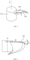
- FIG. 1 is a three-dimensional view of an axial-flow impeller 100 using a blade according to the present application, in which only one blade 112 is shown.
- the axial-flow impeller 100 comprises a hub 110 and a blade 112.
- the hub 110 has a rotation axis X, and a cross section of the hub 110 perpendicular to the rotation axis X is circular.
- the axial-flow impeller 100 may comprise at least two blades 112.
- the at least two blades 112 are evenly arranged on an outer circumferential surface of the hub 110 and are integrally connected to the hub 110.
- the hub 110 and the blade 112 are capable of rotating together about the rotation axis X.
- the axial-flow impeller 100 of the present application rotates about the rotation axis X in a counterclockwise direction (i.e, a direction of rotation indicated by the arrow in FIG. 1 ).
- the dotted arrow in FIG. 1 indicates a flow direction of airflow.
- FIG. 2 is a top view of the axial-flow impeller 100 in FIG. 1 .
- the blade 112 comprises an upper surface 242, a lower surface 244 (see FIG. 3 ), a blade tip 216, a blade root 218, a leading edge 222 and a trailing edge 220.
- the upper surface 242 and the lower surface 244 are disposed oppositely.
- the "leading edge 222" represents a front end edge in a direction of rotation of the blade.
- the “trailing edge 220” represents a rear end edge in the direction of rotation of the blade.
- the "blade root 218" represents an edge where the blade 112 and the hub 110 intersect.
- the "blade tip 216" represents the other edge opposite to the blade root 218.
- the blade tip 216, the blade root 218, the leading edge 222 and the trailing edge 220 surround the upper surface 242 and the lower surface 244.
- the upper surface 242 and the lower surface 244 extend from the blade tip 216 to the blade root 218, respectively, and extend from the leading edge 222 to the trailing edge 220, respectively.
- the blade 112 is capable of rotating about the rotation axis X which is perpendicular to a normal plane.
- the top view of the axial-flow impeller 100 shown in FIG. 2 is also a projection diagram of the axial-flow impeller 100 on the normal plane.
- the blade tip 216 and the blade root 218 of the blade 112 are circular-arc-shaped.
- the blade 112 has varying blade heights in a radially outward direction from the blade root 218 to the blade tip 216. Specifically, a radius where the circular arc of the blade root 218 is located is referred to as "0% blade height".
- a radius where the circular arc of the blade tip 216 is located is referred to as "100% blade height”.
- a connecting line of center points of the blade tip 216 and the blade root 218 of the blade 112 at each position in the radial direction is circular-arc-shaped, which is referred to as "middle blade height L", i.e., "50% blade height”.
- a circumferential included angle between the leading edge 222 and the trailing edge 220 forms a wrap angle ⁇ .
- the wrap angle ⁇ decreases gradually from the blade root 218 to the middle blade height L and increases gradually from the middle blade height L to the blade tip 216.
- the wrap angle ⁇ increases gradually from the middle blade height L to the blade tip 216 so that an area of applying work at the blade tip 216 can be increased and the uniformly distributed load at the position of the blade tip 216 can be reduced.
- a value range of the wrap angle ⁇ is: ⁇ E [40°, 100°]. More specifically, the value range of the wrap angle ⁇ is related to the number of blades 112 that the axial-flow impeller 100 includes.
- the value range of the wrap angle ⁇ is: ⁇ E [80°, 100°].
- the value range of the wrap angle ⁇ is: ⁇ E [60°, 85°].
- the value range of the wrap angle ⁇ is: ⁇ E [40°, 70°].
- the rotation axis X and the normal plane intersect perpendicularly at a foot of a perpendicular O.
- a line connecting any point on the front edge 222 and the foot of the perpendicular O is designated as a first connecting line.
- a line connecting a projection point A of an intersection point of the blade root 218 and the leading edge 222 on the normal plane in a direction of the rotation axis X and the foot of the perpendicular O is designated as a second connecting line.
- An included angle between the first connecting line and the second connecting line is called a starting angle ⁇ .
- the starting angle ⁇ increases gradually in a direction from the blade tip 216 to the blade root 218.
- a value range of the starting angle ⁇ is: ⁇ E [0°, 90°].
- the starting angle ⁇ is beneficial to reduce the noise while maintaining the aerodynamic performance.
- FIG. 3 is a three-dimensional view of the axial-flow impeller 100 in FIG. 1 to show a structure of the blade 112 in the direction of the rotation axis X. As shown in FIG. 3 , the upper surface 242 and the lower surface 244 are curved downwards in a radial cross section from the middle blade height L to the blade tip 216.
- FIG. 4 is a side view of the axial-flow impeller 100 in FIG. 1 viewed in a first direction to show a specific structure of the trailing edge 220.
- a vertical line from a highest point M of the trailing edge 220 in the direction of the rotation axis X to the rotation axis X is designated as a first vertical line
- the first vertical line having a vertical point N on the rotation axis X and a line connecting an intersection point P of the trailing edge 220 and the blade tip 216 and the vertical point N is designated as a third connecting line.
- an included angle between the first vertical line and the third connecting line is a winglet angle ⁇ , and a value range of the winglet angle ⁇ is: ⁇ ⁇ [1°, 15°].
- a trailing end of the blade tip 216 is tilted toward the lower surface 244 in an axial direction so that a relative velocity at the blade tip 216 can be reduced.
- an absolute velocity of a fluid is composed of vectors of the relative velocity and a tangential velocity.
- FIG. 5 is a side view of the axial-flow impeller 100 in FIG. 1 viewed in a second direction to show a specific structure of the leading edge 222.
- a line connecting the intersection point T of the blade root 218 and the leading edge 222 and an intersection point S of the blade tip 216 and the leading edge 222 is designated as a fourth connecting line.
- An included angle between the fourth connecting line and the normal plane is designated as a sweep forward angle ⁇ .
- a value range of the sweep forward angle ⁇ is: ⁇ ⁇ [5°, 30°]; and the leading edge 222 is located in a region formed by a rotation of the sweep forward angle ⁇ about the rotation axis X.
- the region covered by the sweep forward angle ⁇ is a sector, and the region formed by the rotation of the sweep forward angle ⁇ about the rotation axis X forms an annular fan-shaped body.
- the leading edge 222 is located in the annular fan-shaped body.
- the inventors of the present application have found that a traditional blade is generally a twisted smooth streamlined blade, and since serious flow separation on the surface of the blade induces a vortex, it is difficult to avoid leakage from the blade tip.
- the blade 112 of the present application can allow for a lower load at the blade tip 216 and a larger load at the middle blade height, reduced velocity and pressure peaks of the fluid, mitigated pressure and velocity pulsations (i.e., abrupt changes), decreased number of shedding vortices, reduced intensity of shedding vortices, and delaying and suppression of vortex shedding, thus effectively improving the noise.
- the axial-flow impeller 100 of the present application has noise lower than the traditional axial-flow impeller by 2.5 dB.
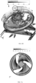
- FIG. 6A is a diagram of surrounding airflow simulation of a traditional axial-flow impeller
- FIG. 6B is a diagram of surrounding airflow simulation of an axial-flow impeller 100 according to the present application.
- turbulent vortices with high flow velocities would be produced by air in the vicinity of the junction of the leading edge and the blade tip of the blade and air in the vicinity of the junction of the trailing edge and the blade tip of the blade.
- FIG. 6A is a diagram of surrounding airflow simulation of a traditional axial-flow impeller
- FIG. 6B is a diagram of surrounding airflow simulation of an axial-flow impeller 100 according to the present application.
- FIG. 7A is a top view of airflow simulation of a traditional axial-flow impeller
- FIG. 7B is a top view of airflow simulation of an axial-flow impeller 100 according to the present application.
- FIG. 7A during the operation of the axial-flow impeller, when air flows across the upper surface of the blade from the leading edge, an airflow with a lower velocity would be formed at a portion near the blade tip, thereby forming a load which is applied to a blade portion near the blade tip.
- FIG. 7A shows that when air flows across the upper surface of the blade from the leading edge, an airflow with a lower velocity would be formed at a portion near the blade tip, thereby forming a load which is applied to a blade portion near the blade tip.
- the load of the airflow on the blade is uniformly lightened such that the velocity of the airflow on the upper surface of the blade near the blade tip is not significantly reduced, resulting in more uniform velocity, mitigated velocity pulsations and reduced noise.
- the noise can also be reduced by a decrease in velocity at a position of the blade tip close to the trailing edge.
Landscapes
- Engineering & Computer Science (AREA)
- Mechanical Engineering (AREA)
- General Engineering & Computer Science (AREA)
- Structures Of Non-Positive Displacement Pumps (AREA)
Abstract
Description
- The present application relates to the field of rotating machinery such as fans, pumps and compressors, and more particularly to a blade and an axial-flow impeller using the same.
- A leading edge and a trailing edge of a traditional blade are usually monotonous smooth curves. Since serious flow separation on the surface of the blade induces a vortex, a loud noise is produced.
- Exemplary embodiments of the present application may address at least some of the above-mentioned problems. According to a first aspect of the present application, the present application provides a blade, comprising a blade tip, a blade root, a leading edge and a trailing edge, wherein the leading edge and the trailing edge extend from the blade tip to the blade root, respectively, and the blade is capable of rotating about a rotation axis X which is perpendicular to a normal plane. In a projection of the blade on the normal plane, a circumferential included angle between the leading edge and the trailing edge forms a wrap angle ϕ, and the wrap angle ϕ decreases gradually from the blade root to a middle blade height of the blade and increases gradually from the middle blade height to the blade tip, wherein the middle blade height is an arc line formed by center points of the blade tip and the blade root along a radial direction.
- According to the blade of the first aspect described above, the rotation axis X and the normal plane intersect perpendicularly at a foot of a perpendicular O. A line connecting any point on the leading edge and the foot of the perpendicular O is designated as a first connecting line, and a line connecting a projection point A of an intersection point of the blade root and the leading edge on the normal plane in a direction of the rotation axis X and the foot of the perpendicular O is a second connecting line. An included angle between the first connecting line and the second connecting line is called a starting angle Θ, wherein the starting angle Θ increases gradually in a direction from the blade tip to the blade root.
- According to the blade of the first aspect described above, a value range of the starting angle Θ is: Θ E [0°, 90°].
- The blade according to the first aspect described above comprises an upper surface and a lower surface. The upper surface and the lower surface are curved downwards in a radial cross section of the blade from the middle blade height to the blade tip.
- According to the blade of the first aspect described above, a vertical line from a highest point on the trailing edge to the rotation axis X is designated as a first vertical line, the first vertical line having a vertical point on the rotation axis X, and a line connecting an intersection point of the trailing edge and the blade tip and the vertical point is designated as a third connecting line. In a projection direction along the rotation axis X, an included angle between the first vertical line and the third connecting line is a winglet angle α, and a value range of the winglet angle α is: α ∈ [1°, 15°].
- According to the blade of the first aspect described above, in the projection direction along the rotation axis X, a line connecting the intersection point of the blade root and the leading edge and an intersection point of the blade tip and the leading edge is designated as a fourth connecting line. An included angle between the fourth connecting line and the normal plane is designated as a sweep forward angle β, and a value range of the sweep forward angle β is: β ∈ [5°, 30°]; and the leading edge is located in a region formed by a rotation of the sweep forward angle β about the rotation axis X.
- According to a second aspect of the present application, the present application provides an axial-flow impeller comprising a hub and at least two blades described above. The hub has a rotation axis X and is capable of rotating about the rotation axis X. The at least two blades are arranged on an outer circumferential surface of the hub.
- According to the axial-flow impeller of the second aspect described above, the wrap angle ϕ is related to a number of the blades.
- According to the axial-flow impeller of the second aspect described above, when the axial-flow impeller has three blades, the value range of the wrap angle ϕ is: ϕ E [80°, 100°]; when the axial-flow impeller has four blades, the value range of the wrap angle ϕ is: ϕ E [60°, 85°]; and when the axial-flow impeller has five blades, the value range of the wrap angle ϕ is: ϕ ∈ [40°, 70°].
- The blade of the present application allows for significantly reduced turbulent vortices in the vicinity of the junction of the leading edge and the blade tip of the blade and in the vicinity of the junction of the trailing edge and the blade tip of the blade during the operation of the axial-flow impeller, leading to evenly lightened load of airflow on the blade, more uniform velocity, mitigated velocity pulsations, and reduced noise.
- The features and advantages of the present application can be better understood when the following detailed description is read with reference to the accompanying drawings. Like reference numerals denote like parts throughout the accompanying drawings, in which:
-
FIG. 1 is a three-dimensional view of an axial-flow impeller using a blade according to the present application; -
FIG. 2 is a top view of the axial-flow impeller inFIG. 1 ; -
FIG. 3 is a three-dimensional view of the axial-flow impeller inFIG. 1 ; -
FIG. 4 is a side view of the axial-flow impeller inFIG. 1 in a first direction; -
FIG. 5 is a side view of the axial-flow impeller inFIG. 1 in a second direction; -
FIG. 6A is a diagram of surrounding airflow simulation of a traditional axial-flow impeller; -
FIG. 6B is a diagram of surrounding airflow simulation of an axial-flow impeller according to the present application; -
FIG. 7A is a top view of airflow simulation of a traditional axial-flow impeller; and -
FIG. 7B is a top view of airflow simulation of an axial-flow impeller according to the present application. - Various embodiments of the present application will be described below with reference to the accompanying drawings that constitute a part of the present description. In the following drawings, identical parts and components are denoted by identical reference numerals.
-
FIG. 1 is a three-dimensional view of an axial-flow impeller 100 using a blade according to the present application, in which only oneblade 112 is shown. As shown inFIG. 1 , the axial-flow impeller 100 comprises ahub 110 and ablade 112. Thehub 110 has a rotation axis X, and a cross section of thehub 110 perpendicular to the rotation axis X is circular. The axial-flow impeller 100 may comprise at least twoblades 112. The at least twoblades 112 are evenly arranged on an outer circumferential surface of thehub 110 and are integrally connected to thehub 110. Thehub 110 and theblade 112 are capable of rotating together about the rotation axis X. As an example, the axial-flow impeller 100 of the present application rotates about the rotation axis X in a counterclockwise direction (i.e, a direction of rotation indicated by the arrow inFIG. 1 ). The dotted arrow inFIG. 1 indicates a flow direction of airflow. It will be appreciated by a person skilled in the art that while thehub 110 shown in the present application is a cylinder, thehub 110, in other embodiments, may also be in other shapes. -
FIG. 2 is a top view of the axial-flow impeller 100 inFIG. 1 . As shown inFIG. 2 , theblade 112 comprises anupper surface 242, a lower surface 244 (seeFIG. 3 ), ablade tip 216, ablade root 218, a leadingedge 222 and atrailing edge 220. Theupper surface 242 and thelower surface 244 are disposed oppositely. Wherein, the "leadingedge 222" represents a front end edge in a direction of rotation of the blade. The "trailing edge 220" represents a rear end edge in the direction of rotation of the blade. The "blade root 218" represents an edge where theblade 112 and thehub 110 intersect. The "blade tip 216" represents the other edge opposite to theblade root 218. Theblade tip 216, theblade root 218, the leadingedge 222 and thetrailing edge 220 surround theupper surface 242 and thelower surface 244. In other words, theupper surface 242 and thelower surface 244 extend from theblade tip 216 to theblade root 218, respectively, and extend from the leadingedge 222 to thetrailing edge 220, respectively. - As shown in
FIG. 2 , theblade 112 is capable of rotating about the rotation axis X which is perpendicular to a normal plane. In other words, the top view of the axial-flow impeller 100 shown inFIG. 2 is also a projection diagram of the axial-flow impeller 100 on the normal plane. In the projection on the normal plane, theblade tip 216 and theblade root 218 of theblade 112 are circular-arc-shaped. Theblade 112 has varying blade heights in a radially outward direction from theblade root 218 to theblade tip 216. Specifically, a radius where the circular arc of theblade root 218 is located is referred to as "0% blade height". A radius where the circular arc of theblade tip 216 is located is referred to as "100% blade height". A connecting line of center points of theblade tip 216 and theblade root 218 of theblade 112 at each position in the radial direction is circular-arc-shaped, which is referred to as "middle blade height L", i.e., "50% blade height". A circumferential included angle between theleading edge 222 and the trailingedge 220 forms a wrap angle ϕ. In theblade 112 shown in the present application, the wrap angle ϕ decreases gradually from theblade root 218 to the middle blade height L and increases gradually from the middle blade height L to theblade tip 216. When theblade 112 rotates, since the middle blade height L of theblade 112 has the smallest wrap angle, a load at the middle blade height L is greater. This allows for a decrease in a load at theblade root 218, thereby improving the strength of theblade root 218. In addition, the wrap angle ϕ increases gradually from the middle blade height L to theblade tip 216 so that an area of applying work at theblade tip 216 can be increased and the uniformly distributed load at the position of theblade tip 216 can be reduced. A value range of the wrap angle ϕ is: ϕ E [40°, 100°]. More specifically, the value range of the wrap angle ϕ is related to the number ofblades 112 that the axial-flow impeller 100 includes. When the axial-flow impeller 100 includes threeblades 112, the value range of the wrap angle ϕ is: ϕ E [80°, 100°]. When the axial-flow impeller 100 includes fourblades 112, the value range of the wrap angle ϕ is: ϕ E [60°, 85°]. When the axial-flow impeller 100 includes threeblades 112, the value range of the wrap angle ϕ is: ϕ E [40°, 70°]. - As shown in
FIG. 2 , in the projection on the normal plane, the rotation axis X and the normal plane intersect perpendicularly at a foot of a perpendicular O. A line connecting any point on thefront edge 222 and the foot of the perpendicular O is designated as a first connecting line. A line connecting a projection point A of an intersection point of theblade root 218 and theleading edge 222 on the normal plane in a direction of the rotation axis X and the foot of the perpendicular O is designated as a second connecting line. An included angle between the first connecting line and the second connecting line is called a starting angle Θ. The starting angle Θ increases gradually in a direction from theblade tip 216 to theblade root 218. As an example, a value range of the starting angle Θ is: Θ E [0°, 90°]. The starting angle Θ is beneficial to reduce the noise while maintaining the aerodynamic performance. -
FIG. 3 is a three-dimensional view of the axial-flow impeller 100 inFIG. 1 to show a structure of theblade 112 in the direction of the rotation axis X. As shown inFIG. 3 , theupper surface 242 and thelower surface 244 are curved downwards in a radial cross section from the middle blade height L to theblade tip 216. -
FIG. 4 is a side view of the axial-flow impeller 100 inFIG. 1 viewed in a first direction to show a specific structure of the trailingedge 220. As shown inFIG. 4 , a vertical line from a highest point M of the trailingedge 220 in the direction of the rotation axis X to the rotation axis X is designated as a first vertical line, the first vertical line having a vertical point N on the rotation axis X and a line connecting an intersection point P of the trailingedge 220 and theblade tip 216 and the vertical point N is designated as a third connecting line. In a projection direction along the rotation axis X, an included angle between the first vertical line and the third connecting line is a winglet angle α, and a value range of the winglet angle α is: α ∈ [1°, 15°]. Thus, a trailing end of theblade tip 216 is tilted toward thelower surface 244 in an axial direction so that a relative velocity at theblade tip 216 can be reduced. More specifically, an absolute velocity of a fluid is composed of vectors of the relative velocity and a tangential velocity. Since the relative velocity at theblade tip 216 is reduced, the absolute velocity of the fluid is reduced, thereby controlling a thickness of a turbulent boundary layer on the wall surface of theupper surface 242, slowing down the separation of the boundary layer, and achieving the delaying and suppression of vortex shedding. As an example, the trailingedge 220 is a smooth quadratic curve in a coordinate system with the first vertical line as the x-axis and the rotation axis X as the y-axis. Specifically, there is a tangent line at each point on the trailingedge 220, and the tangent line rotates continuously as a tangent point moves. Furthermore, a curve equation of the trailingedge 220 is y=ax2+bx+c, where a≠0. -
FIG. 5 is a side view of the axial-flow impeller 100 inFIG. 1 viewed in a second direction to show a specific structure of theleading edge 222. As shown inFIG. 5 , a line connecting the intersection point T of theblade root 218 and theleading edge 222 and an intersection point S of theblade tip 216 and theleading edge 222 is designated as a fourth connecting line. An included angle between the fourth connecting line and the normal plane is designated as a sweep forward angle β. A value range of the sweep forward angle β is: β ∈ [5°, 30°]; and theleading edge 222 is located in a region formed by a rotation of the sweep forward angle β about the rotation axis X. Specifically, the region covered by the sweep forward angle β is a sector, and the region formed by the rotation of the sweep forward angle β about the rotation axis X forms an annular fan-shaped body. Theleading edge 222 is located in the annular fan-shaped body. This arrangement allows for formation of a cavity in thelower surface 244, thereby controlling early separation of the shedding vortex on theupper surface 242 from theblade 112, so as to realize overall load distribution on theblade 112 and achieve a balance between the aerodynamic performance and the acoustic performance. - The inventors of the present application have found that a traditional blade is generally a twisted smooth streamlined blade, and since serious flow separation on the surface of the blade induces a vortex, it is difficult to avoid leakage from the blade tip. The
blade 112 of the present application can allow for a lower load at theblade tip 216 and a larger load at the middle blade height, reduced velocity and pressure peaks of the fluid, mitigated pressure and velocity pulsations (i.e., abrupt changes), decreased number of shedding vortices, reduced intensity of shedding vortices, and delaying and suppression of vortex shedding, thus effectively improving the noise. As an example, when a traditional axial-flow impeller and the axial-flow impeller 100 of the present application operate at 900 r/min, the axial-flow impeller 100 of the present application has noise lower than the traditional axial-flow impeller by 2.5 dB. -
FIG. 6A is a diagram of surrounding airflow simulation of a traditional axial-flow impeller, andFIG. 6B is a diagram of surrounding airflow simulation of an axial-flow impeller 100 according to the present application. As shown inFIG. 6A , during the operation of the axial-flow impeller, turbulent vortices with high flow velocities would be produced by air in the vicinity of the junction of the leading edge and the blade tip of the blade and air in the vicinity of the junction of the trailing edge and the blade tip of the blade. However, as shown inFIG. 6B , during the operation of the axial-flow impeller of the present application, turbulent vortices in the vicinity of the junction of the leading edge and the blade tip of the blade and in the vicinity of the junction of the trailing edge and the blade tip of the blade are significantly reduced. -
FIG. 7A is a top view of airflow simulation of a traditional axial-flow impeller, andFIG. 7B is a top view of airflow simulation of an axial-flow impeller 100 according to the present application. As shown inFIG. 7A , during the operation of the axial-flow impeller, when air flows across the upper surface of the blade from the leading edge, an airflow with a lower velocity would be formed at a portion near the blade tip, thereby forming a load which is applied to a blade portion near the blade tip. However, as shown inFIG. 7B , during the operation of the axial-flow impeller of the present application, the load of the airflow on the blade is uniformly lightened such that the velocity of the airflow on the upper surface of the blade near the blade tip is not significantly reduced, resulting in more uniform velocity, mitigated velocity pulsations and reduced noise. Furthermore, the noise can also be reduced by a decrease in velocity at a position of the blade tip close to the trailing edge. - While only some features of the present application have been illustrated and described herein, various improvements and changes will occur to those skilled in the art. It is therefore to be understood that the appended claims are intended to cover all the improvements and changes that fall within the scope of the spirit of the present application.
Claims (9)
- A blade (112), comprising:a blade tip (216), a blade root (218), a leading edge (222) and a trailing edge (220), wherein the leading edge (222) and the trailing edge (220) extend from the blade tip (216) to the blade root (218), respectively, and the blade (112) is capable of rotating about a rotation axis (X) which is perpendicular to a normal plane;wherein in a projection of the blade (112) on the normal plane, a circumferential included angle between the leading edge (222) and the trailing edge (220) forms a wrap angle ϕ, and the wrap angle ϕ decreases gradually from the blade root (218) to a middle blade height of the blade (112) and increases gradually from the middle blade height to the blade tip (216);wherein the middle blade height is an arc line formed by center points of the blade tip (216) and the blade root (218) along a radial direction.
- The blade (112) according to claim 1, whereinthe rotation axis (X) and the normal plane intersect perpendicularly at a foot of a perpendicular (O), a line connecting any point on the leading edge (222) and the foot of the perpendicular (O) is designated as a first connecting line, a line connecting a projection point (A) of an intersection point of the blade root (218) and the leading edge (222) on the normal plane in a direction of the rotation axis (X) and the foot of the perpendicular (O) is designated as a second connecting line, and an included angle between the first connecting line and the second connecting line is called a starting angle Θ;wherein the starting angle Θ increases gradually in a direction from the blade tip (216) to the blade root (218).
- The blade (112) according to claim 2, wherein
a value range of the starting angle Θ is: Θ ∈ [0°, 90°]. - The blade (112) according to claim 1, whereinthe blade (112) comprises an upper surface (242) and a lower surface (244);the upper surface (242) and the lower surface (244) are curved downwards in a radial cross section of the blade (112) from the middle blade height to the blade tip (216).
- The blade (112) according to claim 4, whereina vertical line from a highest point on the trailing edge (220) to the rotation axis (X) is designated as a first vertical line, the first vertical line having a vertical point on the rotation axis (X), and a line connecting an intersection point of the trailing edge (220) and the blade tip (216) and the vertical point is designated as a third connecting line;in a projection direction along the rotation axis (X), an included angle between the first vertical line and the third connecting line is a winglet angle α, and a value range of the winglet angle α is: α ∈ [1°, 15°].
- The blade (112) according to claim 1, whereinin the projection direction along the rotation axis (X), a line connecting the intersection point of the blade root (218) and the leading edge (222) and an intersection point of the blade tip (216) and the leading edge (222) is designated as a fourth connecting line;an included angle between the fourth connecting line and the normal plane is designated as a sweep forward angle β, and a value range of the sweep forward angle β is: β ∈ [5°, 30°]; andthe leading edge (222) is located in a region formed by a rotation of the sweep forward angle β about the rotation axis (X).
- An axial-flow impeller (100), characterized by comprising:a hub (110) having a rotation axis (X), the hub (110) being capable of rotating about the rotation axis (X); andat least two blades (112) according to any one of claims 1-6, wherein the at least two blades (112) are arranged on an outer circumferential surface of the hub (110).
- The axial-flow impeller (100) according to claim 7, wherein
the wrap angle ϕ is related to a number of the blades (112). - The axial-flow impeller (100) according to claim 8, whereinwhen the axial-flow impeller (100) has three blades (112), the value range of the wrap angle ϕ is: ϕ ∈ [80°, 100°];when the axial-flow impeller (100) has four blades (112), the value range of the wrap angle ϕ is: ϕ ∈ [60°, 85°]; andwhen the axial-flow impeller (100) has five blades (112), the value range of the wrap angle ϕ is: ϕ ∈ [40°, 70°].
Applications Claiming Priority (2)
| Application Number | Priority Date | Filing Date | Title |
|---|---|---|---|
| CN202210741756.6A CN115111194B (en) | 2022-06-27 | 2022-06-27 | Blade and axial flow impeller using the same |
| PCT/CN2023/099661 WO2024001739A1 (en) | 2022-06-27 | 2023-06-12 | Blade and axial impeller using same |
Publications (2)
| Publication Number | Publication Date |
|---|---|
| EP4545800A1 true EP4545800A1 (en) | 2025-04-30 |
| EP4545800A4 EP4545800A4 (en) | 2026-07-08 |
Family
ID=83331023
Family Applications (1)
| Application Number | Title | Priority Date | Filing Date |
|---|---|---|---|
| EP23829922.6A Pending EP4545800A4 (en) | 2022-06-27 | 2023-06-12 | BUCKET AND AXIAL IMPACT WHEELS WITH THAT |
Country Status (4)
| Country | Link |
|---|---|
| US (1) | US20250382971A1 (en) |
| EP (1) | EP4545800A4 (en) |
| CN (1) | CN115111194B (en) |
| WO (1) | WO2024001739A1 (en) |
Families Citing this family (4)
| Publication number | Priority date | Publication date | Assignee | Title |
|---|---|---|---|---|
| CN115111194B (en) * | 2022-06-27 | 2024-05-10 | 约克广州空调冷冻设备有限公司 | Blade and axial flow impeller using the same |
| CN117514909B (en) * | 2023-11-21 | 2026-06-09 | 华中科技大学 | Axial fan rear guide vane and corresponding axial fan |
| CN118194765A (en) * | 2024-04-08 | 2024-06-14 | 东方电气集团东方电机有限公司 | A blade design method for suppressing pressure pulsation, reducing vibration and noise, and an impeller designed therefor |
| CN121993436A (en) * | 2026-04-08 | 2026-05-08 | 盖瑞特动力科技(上海)有限公司 | Compressor, supercharger and engine |
Family Cites Families (15)
| Publication number | Priority date | Publication date | Assignee | Title |
|---|---|---|---|---|
| JPH10311296A (en) * | 1997-05-14 | 1998-11-24 | Matsushita Seiko Co Ltd | Blower |
| JP2006258107A (en) * | 2006-06-30 | 2006-09-28 | Toshiba Kyaria Kk | Axial blower |
| WO2013069397A1 (en) * | 2011-11-10 | 2013-05-16 | 三菱電機株式会社 | External cooling unit of vehicular air-conditioning device |
| CN202326414U (en) * | 2011-11-21 | 2012-07-11 | 珠海格力电器股份有限公司 | Axial flow fan |
| ITMI20120451A1 (en) * | 2012-03-22 | 2013-09-23 | Elica Spa | IMPELLER FOR AXIAL FLUID CONVEYANCE, IN PARTICULAR FOR REFRIGERATION SYSTEMS |
| JP5629721B2 (en) * | 2012-04-10 | 2014-11-26 | シャープ株式会社 | Propeller fan, fluid feeder and mold |
| CN104895838A (en) * | 2014-03-05 | 2015-09-09 | 珠海格力电器股份有限公司 | Axial flow fan blade and axial flow fan |
| CN104389810B (en) * | 2014-09-19 | 2017-11-17 | 江苏大学 | A kind of multi-state design method of multi-phase mixed delivering axial-flow pump impeller |
| CN108506247B (en) * | 2018-05-09 | 2024-08-23 | 约克广州空调冷冻设备有限公司 | Blade and axial flow impeller using same |
| CN208380968U (en) * | 2018-06-20 | 2019-01-15 | 广东美的制冷设备有限公司 | Axial-flow windwheel, air-conditioner outdoor unit and air conditioner |
| CN110500320B (en) * | 2019-08-21 | 2025-01-24 | 广东顺威精密塑料股份有限公司 | An axial flow fan |
| CN110513329B (en) * | 2019-09-30 | 2024-07-19 | 广东美的制冷设备有限公司 | Axial flow fan and air conditioner having the same |
| CN111577655B (en) * | 2020-04-14 | 2021-11-05 | 约克广州空调冷冻设备有限公司 | Blade and axial flow impeller using the same |
| CN113757168A (en) * | 2020-06-01 | 2021-12-07 | 广东美的白色家电技术创新中心有限公司 | Fan blade, fan, air condensing units and air conditioning system |
| CN115111194B (en) * | 2022-06-27 | 2024-05-10 | 约克广州空调冷冻设备有限公司 | Blade and axial flow impeller using the same |
-
2022
- 2022-06-27 CN CN202210741756.6A patent/CN115111194B/en active Active
-
2023
- 2023-06-12 US US18/878,769 patent/US20250382971A1/en active Pending
- 2023-06-12 EP EP23829922.6A patent/EP4545800A4/en active Pending
- 2023-06-12 WO PCT/CN2023/099661 patent/WO2024001739A1/en not_active Ceased
Also Published As
| Publication number | Publication date |
|---|---|
| WO2024001739A1 (en) | 2024-01-04 |
| EP4545800A4 (en) | 2026-07-08 |
| CN115111194A (en) | 2022-09-27 |
| US20250382971A1 (en) | 2025-12-18 |
| CN115111194B (en) | 2024-05-10 |
Similar Documents
| Publication | Publication Date | Title |
|---|---|---|
| US20250382971A1 (en) | Blade and axial impeller using same | |
| CN104641121B (en) | Propeller type fan and possess the air conditioner of this propeller type fan | |
| CN102828997B (en) | Axial flow blower | |
| US9394911B2 (en) | Axial flow fan | |
| CN111577655B (en) | Blade and axial flow impeller using the same | |
| JP2004036567A (en) | Centrifugal compressor impeller | |
| CN111133201B (en) | Propeller Fans and Axial Blowers | |
| CN109790853B (en) | Centrifugal compressors and turbochargers | |
| CN110657126B (en) | Non-axisymmetric hub structure for controlling flow in centrifugal impeller, centrifugal impeller | |
| CN108506247B (en) | Blade and axial flow impeller using same | |
| CN110513329B (en) | Axial flow fan and air conditioner having the same | |
| JPH08177792A (en) | Axial fan | |
| JP7386333B2 (en) | Impeller and centrifugal compressor | |
| JP6930644B1 (en) | Propeller fan | |
| US11519422B2 (en) | Blade and axial flow impeller using same | |
| CN110939603A (en) | Blade and axial flow impeller using same | |
| US20210340992A1 (en) | Blade and axial flow impeller using same | |
| CN112303010B (en) | High-efficiency low-noise centrifugal fan | |
| US12025148B2 (en) | Turbofan | |
| CN110005644B (en) | Axial flow compressor stator with middle casing | |
| CN111577656B (en) | Blade and axial flow impeller using same | |
| CN115898948B (en) | Blades and axial flow fans using them | |
| JPH03267506A (en) | Axial flow turbine stator blade | |
| CN217327809U (en) | Impeller | |
| JP7187542B2 (en) | Centrifugal compressor and turbocharger with this centrifugal compressor |
Legal Events
| Date | Code | Title | Description |
|---|---|---|---|
| STAA | Information on the status of an ep patent application or granted ep patent |
Free format text: STATUS: THE INTERNATIONAL PUBLICATION HAS BEEN MADE |
|
| PUAI | Public reference made under article 153(3) epc to a published international application that has entered the european phase |
Free format text: ORIGINAL CODE: 0009012 |
|
| STAA | Information on the status of an ep patent application or granted ep patent |
Free format text: STATUS: REQUEST FOR EXAMINATION WAS MADE |
|
| 17P | Request for examination filed |
Effective date: 20250127 |
|
| AK | Designated contracting states |
Kind code of ref document: A1 Designated state(s): AL AT BE BG CH CY CZ DE DK EE ES FI FR GB GR HR HU IE IS IT LI LT LU LV MC ME MK MT NL NO PL PT RO RS SE SI SK SM TR |
|
| DAV | Request for validation of the european patent (deleted) | ||
| DAX | Request for extension of the european patent (deleted) | ||
| A4 | Supplementary search report drawn up and despatched |
Effective date: 20260605 |
|
| RIC1 | Information provided on ipc code assigned before grant |
Ipc: F04D 29/38 20060101AFI20260529BHEP Ipc: F04D 29/66 20060101ALI20260529BHEP |