EP4545789A1 - Circulation bypass arrangement for being connected to a hydraulic system, and method for removing and/or exchanging a wear part and/or for removing and/or exchanging at least part of a circulation bypass arrangement - Google Patents
Circulation bypass arrangement for being connected to a hydraulic system, and method for removing and/or exchanging a wear part and/or for removing and/or exchanging at least part of a circulation bypass arrangement Download PDFInfo
- Publication number
- EP4545789A1 EP4545789A1 EP23306850.1A EP23306850A EP4545789A1 EP 4545789 A1 EP4545789 A1 EP 4545789A1 EP 23306850 A EP23306850 A EP 23306850A EP 4545789 A1 EP4545789 A1 EP 4545789A1
- Authority
- EP
- European Patent Office
- Prior art keywords
- arrangement
- connecting part
- circulation
- connection
- circulation bypass
- Prior art date
- Legal status (The legal status is an assumption and is not a legal conclusion. Google has not performed a legal analysis and makes no representation as to the accuracy of the status listed.)
- Pending
Links
Images


Classifications
-
- F—MECHANICAL ENGINEERING; LIGHTING; HEATING; WEAPONS; BLASTING
- F04—POSITIVE - DISPLACEMENT MACHINES FOR LIQUIDS; PUMPS FOR LIQUIDS OR ELASTIC FLUIDS
- F04B—POSITIVE-DISPLACEMENT MACHINES FOR LIQUIDS; PUMPS
- F04B49/00—Control, e.g. of pump delivery, or pump pressure of, or safety measures for, machines, pumps, or pumping installations, not otherwise provided for, or of interest apart from, groups F04B1/00 - F04B47/00
- F04B49/22—Control, e.g. of pump delivery, or pump pressure of, or safety measures for, machines, pumps, or pumping installations, not otherwise provided for, or of interest apart from, groups F04B1/00 - F04B47/00 by means of valves
- F04B49/24—Bypassing
-
- F—MECHANICAL ENGINEERING; LIGHTING; HEATING; WEAPONS; BLASTING
- F04—POSITIVE - DISPLACEMENT MACHINES FOR LIQUIDS; PUMPS FOR LIQUIDS OR ELASTIC FLUIDS
- F04B—POSITIVE-DISPLACEMENT MACHINES FOR LIQUIDS; PUMPS
- F04B53/00—Component parts, details or accessories not provided for in, or of interest apart from, groups F04B1/00 - F04B23/00 or F04B39/00 - F04B47/00
- F04B53/10—Valves; Arrangement of valves
- F04B53/1002—Ball valves
-
- F—MECHANICAL ENGINEERING; LIGHTING; HEATING; WEAPONS; BLASTING
- F04—POSITIVE - DISPLACEMENT MACHINES FOR LIQUIDS; PUMPS FOR LIQUIDS OR ELASTIC FLUIDS
- F04B—POSITIVE-DISPLACEMENT MACHINES FOR LIQUIDS; PUMPS
- F04B53/00—Component parts, details or accessories not provided for in, or of interest apart from, groups F04B1/00 - F04B23/00 or F04B39/00 - F04B47/00
- F04B53/20—Filtering
-
- F—MECHANICAL ENGINEERING; LIGHTING; HEATING; WEAPONS; BLASTING
- F04—POSITIVE - DISPLACEMENT MACHINES FOR LIQUIDS; PUMPS FOR LIQUIDS OR ELASTIC FLUIDS
- F04B—POSITIVE-DISPLACEMENT MACHINES FOR LIQUIDS; PUMPS
- F04B53/00—Component parts, details or accessories not provided for in, or of interest apart from, groups F04B1/00 - F04B23/00 or F04B39/00 - F04B47/00
- F04B53/22—Arrangements for enabling ready assembly or disassembly
-
- A—HUMAN NECESSITIES
- A62—LIFE-SAVING; FIRE-FIGHTING
- A62C—FIRE-FIGHTING
- A62C35/00—Permanently-installed equipment
- A62C35/58—Pipe-line systems
- A62C35/68—Details, e.g. of pipes or valve systems
Definitions
- the present invention relates a circulation bypass arrangement for being connected to a hydraulic system, wherein the circulation bypass arrangement comprises a connecting part and a circulation pump unit, and wherein the circulation bypass arrangement is connected to the hydraulic system using a first and a second connection arrangement, wherein the circulation bypass arrangement is configured to be connected to the first and second connection arrangements using a plurality of screw connections.
- the present invention relates to a corresponding method for removing and/or exchanging a wear part and/or for removing and/or exchanging at least part of a circulation bypass arrangement, wherein the circulation bypass arrangement is connected to a hydraulic system and comprises a circulation pump unit and a connecting part housing the wear part, and wherein the circulation bypass arrangement is connected to the hydraulic system using a first and a second connection arrangement and using a plurality of screw connections.
- Circulation bypass arrangements for being connected to a hydraulic system are generally know.
- automatic fire sprinkler systems are generally known that comprise flow detectors and one-way valves that may be required to be tested, and, in order to conduct such tests, such sprinkler systems are known to be arranged such as to comprise closed loop (or circulation bypass) arrangements - at locations of such flow detectors or of such one-way valves - in order to be able to locally cause a flow of a liquid which flow is able to be detected by the respective flow detector.
- Such circulation bypass arrangement or closed loop arrangements are known to comprise at least a circulation pump unit, and are furthermore known to be connected to a portion - typically comprising a flow detector - of such an automatic fire sprinkler system or such a hydraulic system, typically by means of a plurality of screw connections.
- An object of the present invention is to provide a technically simple, effective and cost-effective solution for arranging a circulation bypass arrangement (or a closed loop arrangement) that is to be connected, by means of using a first and second connection arrangement, to a hydraulic system - especially an automatic fire sprinkler system, and especially a portion thereof comprising a flow detector- in a manner such as to be able to comparatively easily and comparatively effortlessly disassemble the circulation bypass arrangement or closed loop arrangement, especially without the need to also remove or separate the first and/or second connection arrangement from the hydraulic system and/or to disassemble the first and/or second connection arrangement.
- a further object of the present invention is to provide a corresponding method for removing and/or exchanging a wear part and/or for removing and/or exchanging at least part of a circulation bypass arrangement.
- the object of the present invention is achieved by a circulation bypass arrangement for being connected to a hydraulic system, wherein the circulation bypass arrangement comprises a connecting part and a circulation pump unit, and wherein the circulation bypass arrangement is connected to the hydraulic system using a first and a second connection arrangement,
- the circulation bypass arrangement comprises a wear part
- the connecting part and the circulation pump unit are connected with each other by means of a union nut; especially the connecting part and the circulation pump unit are connected with each other by means of the union nut in a manner such that the connection part has, or comprises, the union nut. Furthermore according to the present invention, the connecting part and the first connection arrangement (without restriction of generality) are connected with each other by means of a lock nut.
- the connecting part has, or comprises, both the union nut and the lock nut; this provides - especially by means of an interaction (of a thread portion) of the connecting part with a corresponding thread portion of the first connection arrangement, the corresponding thread portion having, or being, an internal thread - the possibility to easily disassemble the circulation bypass (or closed loop) arrangement, and, if applicable, to replace and/or remove and/or exchange the wear part.
- the circulation bypass arrangement advantageously provides the possibility to avoid drawbacks associated with such removal and/or exchange of at least a part of the circulation bypass arrangement and, especially with such removal and/or exchange of a wear part in relation to hydraulic systems conventionally known.
- drawbacks include, e.g., quality problems related to leakage due to the difficulty to center the wear part, especially in case the wear part corresponds to a non-return valve.
- a further union nut is used for connecting the second connection arrangement with the circulation pump unit - especially the other side of the circulation pump unit (compared to the side of the circulation pump unit that is connected to the connecting part).
- the lock nut is used - at the connection of the connecting part to the first connection arrangement - together with a sealing means, wherein the sealing means is especially a sealing ring, especially an O-ring.
- the connecting part comprises a first thread portion and a second thread portion, wherein the first thread portion is used to screw the connecting part into an internal thread of the first connection arrangement and wherein the second thread portion is used as connection between the connecting part and the lock nut.
- the connecting part comprises a groove portion between the first thread portion and the second thread portion, wherein the groove portion is especially used to receive or to contain the sealing means between the connecting part and the first connection arrangement.
- the connecting part houses a wear part, wherein the wear part especially corresponds to a check valve or to a non-return valve or to a filter element.
- the hydraulic system comprises a tube or tube part, wherein the tube or tube part is especially located parallel (or substantially parallel) to the circulation bypass arrangement (especially parallel to the pumping direction of the circulation pump unit), wherein the tube or tube part especially comprises a flow detector entity.
- the first and second connection arrangement comprises,
- the present invention relates to a method for removing and/or exchanging a wear part and/or for removing and/or exchanging at least part of a circulation bypass arrangement
- the circulation bypass arrangement is connected to a hydraulic system and comprises a circulation pump unit and a connecting part housing the wear part
- the circulation bypass arrangement is connected to the hydraulic system using a first and a second connection arrangement and using a plurality of screw connections, characterized in that the connecting part and the circulation pump unit are connected with each other by means of a union nut, and that the connecting part and the first connection arrangement are connected with each other by means of a lock nut
- the method comprises the following steps:
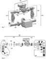
- FIG. 1 a perspective view of an exemplary embodiment of a circulation bypass arrangement 100 according to the present invention is schematically shown:
- the circulation bypass arrangement 100 is shown comprising a circulation pump unit 130, wherein the circulation bypass arrangement 100 is connected to a hydraulic system 200 by means of a first connection arrangement 210 and a second connection arrangement 220, and wherein the circulation bypass arrangement 100 comprises, in addition to the circulation pump unit 130, a connecting part 120.
- Figure 1 shows an arrow, wherein the arrow on the right hand side is crossed out, and wherein the arrow on the left hand side (towards the first connection arrangement 210) is not crossed out.
- the arrow on the left hand side indicates that it is possible, according to the present invention, to create an axial distance or space for facilitating the disassembly of the circulation bypass arrangement, or of at least part thereof.
- Figure 1 furthermore shows the hydraulic system 200 to also comprise - besides the first connection arrangement 210 and the second connection arrangement 220 - a tube or tube part 230, wherein the tube or tube part 230 comprises a flow detector entity 231.
- the tube or tube part 230 is located (or mainly extended) parallel to the (main extension direction of the) circulation bypass arrangement 100.
- FIG 2 an exploded view of the circulation bypass arrangement 100 according to the present invention is schematically shown.
- Figure 2 also shows a representation of the first and second connection arrangements 210, 220 - the first connection arrangement 210 in non-exploded form and the second connection arrangement 220 in rather exploded form.
- both the first and the second connection arrangements 210, 220 comprise, respectively, a valve - wherein especially the valve 211 of the first connection arrangement 210 and/or the valve 221 of the second connection arrangement 220 are or correspond to a ball valve or ball valves.
- first and second connection arrangements 210, 220 are predominantly oriented orthogonal to the main extension direction of the circulation bypass arrangement 100 (and of the tube or tube part 230). Furthermore, the first and second connection arrangements 210, 220, respectively, comprise a 90° pipe angle 212, 222, especially having internal threads (not shown/visible in Figure 2 ).
- the circulation bypass arrangement 100 is connected to the respective one of the first and second connection arrangements 210, 220 - according to the present invention using a plurality of screw connections; in Figure 2 , these screw connections (of the circulation bypass arrangement 100) are shown to be realized with the 90° pipe angles 212, 222 of the first and second connection arrangements 210, 220.
- the circulation bypass arrangement 100 comprises (and Figure 2 shows) the circulation pump unit 130 as well as the connecting part 120, wherein the connecting part 120 and the circulation pump unit 130 are connected with each other by means of a union nut 125 (in a generally known manner, typically using a sealing ring 125', especially an O-ring), and that the connecting part 120 and the first connection arrangement 210 (especially via its 90° pipe angle 212) are connected with each other by means of a lock nut 126.
- Figure 2 also shows a further union nut 135 that is used for connecting the second connection arrangement 220 with the circulation pump unit 130 (in a generally known manner, typically using a sealing ring 135', especially an O-ring).
- the connecting part 120 houses a wear part 110, especially a check valve or a non-return valve or a filter element.
- FIG 3 an exploded view as well as a perspective view of the connecting part 120, the union nut 125 and the lock nut 126 according to the present invention is schematically shown together with a sealing means 126' (related to (or interacting with) the lock nut 126) and the wear part 110.
- the sealing means 126' is especially realized as a sealing ring, especially an O-ring.
- the connecting part 120 comprises a first thread portion 127 as well as a second thread portion 128; in between the first and second thread portions 127, 128, the connecting part 120 comprises a groove portion 126" where the sealing means 126' is located.
- the first thread portion 127 is used to screw the connecting part 120 into an internal thread (of the 90° pipe angle 212 - not shown in Figure 3 ) of the first connection arrangement 210.
- the second thread portion 128 is used as connection between the connecting part 120 and the lock nut 126.
- the first and second thread portions 127, 128 as well as the groove portion 126" in between both are also visible from the schematical side view of the connecting part 120 that is provided by Figure 5 .
- FIG. 6 This interaction between the 90° pipe angle 212 of the first connection arrangement 210, the connecting part 120 and the lock nut 126 (as well as the sealing means 126') is schematically shown in Figure 6 , by means of two sectional views: On a left hand sectional view, the assembled relative positions of the elements or components is represented, i.e. in a situation when the circulation bypass arrangement 100 is in its fixed, or mounted, (and tight) state; in such a situation, the connecting part 120 - by means of its first (external) thread portion 127 is screwed into the internal thread of the 90° pipe angle 212 (i.e., more generally, into an internal thread of the first connection arrangement 210).
- the area of the internal thread of the first connection arrangement 210 is indicated, in Figure 6 (left hand side) by means of reference sign 212'.
- the lock nut 126 (that interacts with - i.e. is screwed on - the second (external) thread portion 128 of the connecting part 120) is - in the situation shown on the left hand side of Figure 6 - pulled tight against the first connection arrangement 210, i.e. especially the 90° pipe angle 212.
- This connection is sealed by means of the sealing means 126' that is located in the groove portion 126" between the first and second thread portions 127, 128 of the connecting part 120.
- the sealing means 126' (shown on the right hand side of Figure 6 ) is no longer compressed between the first connection arrangement 210 / 90° pipe angle 212.
- the connecting part 120 is able to be rotated, it is possible to screw it further into the internal thread of the first connection arrangement 210, i.e. especially the 90° pipe angle 212 - and, thus, provide the possibility to create an axial distance or space for facilitating the disassembly of the circulation bypass arrangement 100.
- FIG 4 a) to f) different operational steps are schematically shown that illustrate the inventive method for removing and/or exchanging the wear part 110 and/or for removing and/or exchanging at least part of a circulation bypass arrangement 100:
- Figure 4a schematically shows that the two valves 211, 221 (shown in Figure 2 ) of the first and second connection arrangement 210, 220, respectively, are closed such that the circulation bypass arrangement 100 is (hydraulically) separated from the residual part of the hydraulic system 200.
- Figure 4b schematically shows that the union nut 125 (connecting, or fastening, the circulation pump unit 130 with the connecting part 120) is loosened, and, likewise, that the lock nut 126 (fixing the (other side of the) connecting part 120 with the first connection arrangement 210 / 90° pipe angle 212) is loosened.
- Figure 4d shows that, due to this axial distance, the union nut 135 on the other side of the circulation pump unit 130 (opposite of the connecting part 120) can be opened or loosened such as to be able to remove the circulation pump unit 130; this is represented in Figure 4e ).
- Figure 4f finally shows the removal of the connection part 120 and the possibility to remove, or to exchange, the wear part 110 housed or located in the connection part 120 of the circulation bypass arrangement 100.
- the inventive method for removing and/or exchanging the wear part 110 and/or for removing and/or exchanging at least part of the circulation bypass arrangement 100 is able to be applied: the connecting part 120 comprises, or interacts with, the union nut 125 as well as the lock nut 126 and the method comprises loosening or opening both in order to create the axial distance or space.
Landscapes
- Engineering & Computer Science (AREA)
- Mechanical Engineering (AREA)
- General Engineering & Computer Science (AREA)
- Details Of Reciprocating Pumps (AREA)
Abstract
The invention relates to a circulation bypass arrangement for being connected to a hydraulic system, wherein the circulation bypass arrangement comprises a connecting part and a circulation pump unit, and wherein the circulation bypass arrangement is connected to the hydraulic system using a first and a second connection arrangement wherein the circulation bypass arrangement is configured to be connected to the first and second connection arrangements using a plurality of screw connections, wherein the connecting part and the circulation pump unit are connected with each other by means of a union nut, and that the connecting part and the first connection arrangement are connected with each other by means of a lock nut.
Description
- The present invention relates a circulation bypass arrangement for being connected to a hydraulic system, wherein the circulation bypass arrangement comprises a connecting part and a circulation pump unit, and wherein the circulation bypass arrangement is connected to the hydraulic system using a first and a second connection arrangement, wherein the circulation bypass arrangement is configured to be connected to the first and second connection arrangements using a plurality of screw connections.
- Furthermore, the present invention relates to a corresponding method for removing and/or exchanging a wear part and/or for removing and/or exchanging at least part of a circulation bypass arrangement, wherein the circulation bypass arrangement is connected to a hydraulic system and comprises a circulation pump unit and a connecting part housing the wear part, and wherein the circulation bypass arrangement is connected to the hydraulic system using a first and a second connection arrangement and using a plurality of screw connections.
- Circulation bypass arrangements for being connected to a hydraulic system are generally know. Furthermore, automatic fire sprinkler systems are generally known that comprise flow detectors and one-way valves that may be required to be tested, and, in order to conduct such tests, such sprinkler systems are known to be arranged such as to comprise closed loop (or circulation bypass) arrangements - at locations of such flow detectors or of such one-way valves - in order to be able to locally cause a flow of a liquid which flow is able to be detected by the respective flow detector.
- Such circulation bypass arrangement or closed loop arrangements are known to comprise at least a circulation pump unit, and are furthermore known to be connected to a portion - typically comprising a flow detector - of such an automatic fire sprinkler system or such a hydraulic system, typically by means of a plurality of screw connections.
- However, conventionally known circulation bypass arrangements or closed loop arrangements are arranged such as to require considerable effort to disassemble, especially in order to check and/or exchange an element of the circulation bypass arrangement or closed loop arrangement.
- An object of the present invention is to provide a technically simple, effective and cost-effective solution for arranging a circulation bypass arrangement (or a closed loop arrangement) that is to be connected, by means of using a first and second connection arrangement, to a hydraulic system - especially an automatic fire sprinkler system, and especially a portion thereof comprising a flow detector- in a manner such as to be able to comparatively easily and comparatively effortlessly disassemble the circulation bypass arrangement or closed loop arrangement, especially without the need to also remove or separate the first and/or second connection arrangement from the hydraulic system and/or to disassemble the first and/or second connection arrangement. Especially, it should be able to check and/or to remove and/or to replace a wear part (being part of the circulation bypass arrangement) comparatively easily and comparatively effortlessly. Furthermore, such checking and/or removing and/or replacing of the wear part shall be possible without increased tightness problems and/or leakages (e.g. due to misalignment of components). A further object of the present invention is to provide a corresponding method for removing and/or exchanging a wear part and/or for removing and/or exchanging at least part of a circulation bypass arrangement.
- The object of the present invention is achieved by a circulation bypass arrangement for being connected to a hydraulic system, wherein the circulation bypass arrangement comprises a connecting part and a circulation pump unit, and wherein the circulation bypass arrangement is connected to the hydraulic system using a first and a second connection arrangement,
- wherein the circulation bypass arrangement is configured to be connected to the first and second connection arrangements using a plurality of screw connections,
- characterized in that the connecting part and the circulation pump unit are connected with each other by means of a union nut, and that the connecting part and the first connection arrangement are connected with each other by means of a lock nut.
- It is thereby advantageously possible according to the present invention to provide the possibility to create an axial distance or space for facilitating the disassembly of the circulation bypass arrangement, or of at least part thereof. Especially in case that the circulation bypass arrangement comprises a wear part, it is advantageously possible, according to the present invention, to facilitate the removal and/or the exchange of the wear part and/or at least a part of a circulation bypass arrangement.
- According to the present invention, the connecting part and the circulation pump unit are connected with each other by means of a union nut; especially the connecting part and the circulation pump unit are connected with each other by means of the union nut in a manner such that the connection part has, or comprises, the union nut. Furthermore according to the present invention, the connecting part and the first connection arrangement (without restriction of generality) are connected with each other by means of a lock nut. Hence, the connecting part has, or comprises, both the union nut and the lock nut; this provides - especially by means of an interaction (of a thread portion) of the connecting part with a corresponding thread portion of the first connection arrangement, the corresponding thread portion having, or being, an internal thread - the possibility to easily disassemble the circulation bypass (or closed loop) arrangement, and, if applicable, to replace and/or remove and/or exchange the wear part.
- Once the axial distance or space is realized, by means of loosening both the union nut and the lock nut, and by means of rotating the connecting part further into the internal thread (corresponding thread portion) of the first connection arrangement, it is advantageously possible to comparatively easily and quickly remove and/or exchange at least a part of the circulation bypass arrangement, and/or, if applicable, to remove and/or exchange the wear part; especially, it is advantageously possible according to the present invention that - during such a removal and/or an exchange of at least a part of the circulation bypass arrangement - the connections of both the first and of the second connection arrangements towards the hydraulic system remain untouched, thereby reducing any risks of generating leakages at such connections and by means of such a procedure.
- Hence, according to the present invention, the circulation bypass arrangement advantageously provides the possibility to avoid drawbacks associated with such removal and/or exchange of at least a part of the circulation bypass arrangement and, especially with such removal and/or exchange of a wear part in relation to hydraulic systems conventionally known. Such drawbacks include, e.g., quality problems related to leakage due to the difficulty to center the wear part, especially in case the wear part corresponds to a non-return valve.
- According to the present invention, it is advantageously possible and preferred that a further union nut is used for connecting the second connection arrangement with the circulation pump unit - especially the other side of the circulation pump unit (compared to the side of the circulation pump unit that is connected to the connecting part).
- It is thereby advantageously possible to realize and implement the inventive method in a comparatively simple and efficient manner.
- According to the present invention, it is advantageously furthermore possible and preferred that the lock nut is used - at the connection of the connecting part to the first connection arrangement - together with a sealing means, wherein the sealing means is especially a sealing ring, especially an O-ring.
- It is thereby advantageously possible to realize and implement the inventive method in a comparatively simple and efficient manner.
- According to the present invention, it is furthermore advantageously possible and preferred that the connecting part comprises a first thread portion and a second thread portion, wherein the first thread portion is used to screw the connecting part into an internal thread of the first connection arrangement and wherein the second thread portion is used as connection between the connecting part and the lock nut.
- It is thereby advantageously possible to realize and implement the inventive method in a comparatively simple and efficient manner. Especially, it is advantageously possible to realize the internal thread as part of the first connection arrangement.
- According to the present invention, it is furthermore advantageously possible and preferred that the connecting part comprises a groove portion between the first thread portion and the second thread portion, wherein the groove portion is especially used to receive or to contain the sealing means between the connecting part and the first connection arrangement.
- It is thereby advantageously possible to realize and implement the inventive method in a comparatively simple and efficient manner.
- Furthermore, it is advantageously possible and preferred according to the present invention that the connecting part houses a wear part, wherein the wear part especially corresponds to a check valve or to a non-return valve or to a filter element.
- It is thereby advantageously possible to realize and implement the inventive method in a comparatively simple and efficient manner; especially, it is advantageously possible to realize the wear part such that only the wear part and/or the connecting part need to be specifically configured in order to implement the present invention.
- Furthermore, it is advantageously possible and preferred according to the present invention that the hydraulic system comprises a tube or tube part, wherein the tube or tube part is especially located parallel (or substantially parallel) to the circulation bypass arrangement (especially parallel to the pumping direction of the circulation pump unit), wherein the tube or tube part especially comprises a flow detector entity.
- It is thereby advantageously possible to realize and implement the inventive method in a comparatively simple and efficient manner.
- Furthermore, it is advantageously possible and preferred according to the present invention that the first and second connection arrangement comprises,
- respectively, a valve, wherein the valve of the first connection arrangement and/or the valve of the second connection arrangement are or correspond to ball valve or ball valves,
- wherein especially the first and second connection arrangement comprise, respectively, a 90 degree pipe angle, especially having internal threads.
- It is thereby advantageously possible to realize and implement the inventive method in a comparatively simple and efficient manner.
- Furthermore, the present invention relates to a method for removing and/or exchanging a wear part and/or for removing and/or exchanging at least part of a circulation bypass arrangement, wherein the circulation bypass arrangement is connected to a hydraulic system and comprises a circulation pump unit and a connecting part housing the wear part, and wherein the circulation bypass arrangement is connected to the hydraulic system using a first and a second connection arrangement and using a plurality of screw connections,
characterized in that the connecting part and the circulation pump unit are connected with each other by means of a union nut, and that the connecting part and the first connection arrangement are connected with each other by means of a lock nut, wherein the method comprises the following steps: - -- in a first step, the union nut, connecting the connecting part with the circulation pump unit, is loosened or opened as well as the lock nut, at the connection of the connecting part with the first connection arrangement, is loosened,
- -- in a second step, the connecting part is further screwed onto and in the direction of an internal thread of the first connection arrangement,
- -- in a third step, the circulation pump unit is removed by means of loosening or opening a further union nut used for connecting the second connection arrangement with the circulation pump unit,
- -- in a fourth step, the connecting part is loosened and removed from the first connection arrangement.
- These and other characteristics, features and advantages of the present invention will become apparent from the following detailed description, taken in conjunction with the accompanying drawings, which illustrate, by way of example, the principles of the invention. The description is given for the sake of example only, without limiting the scope of the invention. The reference figures quoted below refer to the attached drawings.
-
-
Figure 1 schematically illustrates an exemplary embodiment of the present invention, according to a perspective view: A circulation bypass arrangement is shown comprising a circulation pump unit, wherein the circulation bypass arrangement is connected to a hydraulic system by means of a first and a second connection arrangement, and wherein the circulation bypass arrangement comprises, in addition to the circulation pump unit, a connecting part. -
Figure 2 schematically illustrates an exploded view of the circulation bypass arrangement according to the present invention, as well as a representation of the first and second connection arrangement. -
Figure 3 schematically illustrates an exploded view of the connecting part, as well as a perspective view of the connecting part according to the present invention. -
Figure 4 a) to f) schematically illustrates - by means of showing different operational steps - the inventive method for removing and/or exchanging the wear part and/or for removing and/or exchanging at least part of a circulation bypass arrangement. -
Figure 5 schematically illustrates, in a side view, the connecting part. -
Figure 6 schematically illustrates two representations of a sectional view of the connecting part, the first connection arrangement, the lock nut and the sealing means, illustrating the interaction between these elements or components. - The present invention will be described with respect to particular embodiments and with reference to certain drawings, but the invention is not limited thereto but only by the claims. The drawings described are only schematic and are nonlimiting. In the drawings, the size of some of the elements may be exaggerated and not drawn on scale for illustrative purposes.
- Where an indefinite or definite article is used when referring to a singular noun, e.g. "a", "an", "the", this includes a plural of that noun unless something else is specifically stated.
- Furthermore, the terms first, second, third and the like in the description and in the claims are used for distinguishing between similar elements and not necessarily for describing a sequential or chronological order. It is to be understood that the terms so used are interchangeable under appropriate circumstances and that the embodiments of the invention described herein are capable of operation in other sequences than described or illustrated herein.
- In
Figure 1 , a perspective view of an exemplary embodiment of acirculation bypass arrangement 100 according to the present invention is schematically shown: Thecirculation bypass arrangement 100 is shown comprising acirculation pump unit 130, wherein thecirculation bypass arrangement 100 is connected to ahydraulic system 200 by means of afirst connection arrangement 210 and asecond connection arrangement 220, and wherein thecirculation bypass arrangement 100 comprises, in addition to thecirculation pump unit 130, a connectingpart 120. - At both sides of the
circulation bypass arrangement 100,Figure 1 shows an arrow, wherein the arrow on the right hand side is crossed out, and wherein the arrow on the left hand side (towards the first connection arrangement 210) is not crossed out. The arrow on the left hand side indicates that it is possible, according to the present invention, to create an axial distance or space for facilitating the disassembly of the circulation bypass arrangement, or of at least part thereof. -
Figure 1 furthermore shows thehydraulic system 200 to also comprise - besides thefirst connection arrangement 210 and the second connection arrangement 220 - a tube ortube part 230, wherein the tube ortube part 230 comprises aflow detector entity 231. As can be seen fromFigure 1 , the tube ortube part 230 is located (or mainly extended) parallel to the (main extension direction of the)circulation bypass arrangement 100. - In
Figure 2 , an exploded view of thecirculation bypass arrangement 100 according to the present invention is schematically shown.Figure 2 also shows a representation of the first andsecond connection arrangements 210, 220 - thefirst connection arrangement 210 in non-exploded form and thesecond connection arrangement 220 in rather exploded form. FromFigure 2 , it can be seen that both the first and thesecond connection arrangements valve 211 of thefirst connection arrangement 210 and/or thevalve 221 of thesecond connection arrangement 220 are or correspond to a ball valve or ball valves. - In themselves, the first and
second connection arrangements second connection arrangements pipe angle Figure 2 ). - On both of its sides (or ends), the
circulation bypass arrangement 100 is connected to the respective one of the first andsecond connection arrangements 210, 220 - according to the present invention using a plurality of screw connections; inFigure 2 , these screw connections (of the circulation bypass arrangement 100) are shown to be realized with the 90° pipe angles 212, 222 of the first andsecond connection arrangements - As already said, the
circulation bypass arrangement 100 comprises (andFigure 2 shows) thecirculation pump unit 130 as well as the connectingpart 120, wherein the connectingpart 120 and thecirculation pump unit 130 are connected with each other by means of a union nut 125 (in a generally known manner, typically using a sealing ring 125', especially an O-ring), and that the connectingpart 120 and the first connection arrangement 210 (especially via its 90° pipe angle 212) are connected with each other by means of alock nut 126.Figure 2 also shows afurther union nut 135 that is used for connecting thesecond connection arrangement 220 with the circulation pump unit 130 (in a generally known manner, typically using a sealing ring 135', especially an O-ring). - Especially according to the present invention, the connecting
part 120 houses awear part 110, especially a check valve or a non-return valve or a filter element. - In
Figure 3 an exploded view as well as a perspective view of the connectingpart 120, theunion nut 125 and thelock nut 126 according to the present invention is schematically shown together with a sealing means 126' (related to (or interacting with) the lock nut 126) and thewear part 110. The sealing means 126' is especially realized as a sealing ring, especially an O-ring. The connectingpart 120 comprises afirst thread portion 127 as well as asecond thread portion 128; in between the first andsecond thread portions part 120 comprises agroove portion 126" where the sealing means 126' is located. Thefirst thread portion 127 is used to screw the connectingpart 120 into an internal thread (of the 90° pipe angle 212 - not shown inFigure 3 ) of thefirst connection arrangement 210. Thesecond thread portion 128 is used as connection between the connectingpart 120 and thelock nut 126. - The first and
second thread portions groove portion 126" in between both are also visible from the schematical side view of the connectingpart 120 that is provided byFigure 5 . - This interaction between the 90°
pipe angle 212 of thefirst connection arrangement 210, the connectingpart 120 and the lock nut 126 (as well as the sealing means 126') is schematically shown inFigure 6 , by means of two sectional views: On a left hand sectional view, the assembled relative positions of the elements or components is represented, i.e. in a situation when thecirculation bypass arrangement 100 is in its fixed, or mounted, (and tight) state; in such a situation, the connecting part 120 - by means of its first (external)thread portion 127 is screwed into the internal thread of the 90° pipe angle 212 (i.e., more generally, into an internal thread of the first connection arrangement 210). The area of the internal thread of thefirst connection arrangement 210 is indicated, inFigure 6 (left hand side) by means of reference sign 212'. The lock nut 126 (that interacts with - i.e. is screwed on - the second (external)thread portion 128 of the connecting part 120) is - in the situation shown on the left hand side ofFigure 6 - pulled tight against thefirst connection arrangement 210, i.e. especially the 90°pipe angle 212. This connection is sealed by means of the sealing means 126' that is located in thegroove portion 126" between the first andsecond thread portions part 120. - It can be seen, on the left hand side representation of
Figure 6 , that thefirst thread portion 127 of the connectingpart 120 is - in the assembled or fixed state of the circulation bypass arrangement 100 - not completely screwed into the internal thread of the first connection arrangement 210 (i.e. of the 90° pipe angle 212), i.e. in case that thelock nut 126 is loosened, the connectingpart 120 would be able to be screwed further into this internal thread. This situation is shown in the right hand side sectional view ofFigure 6 : Thelock nut 126 is loosened, i.e. screwed (on the second thread portion 128) away from the first thread portion 127 (and, thus, also away from thefirst connection arrangement 210, i.e. especially the 90° pipe angle 212). Hence, the sealing means 126' (shown on the right hand side ofFigure 6 ) is no longer compressed between thefirst connection arrangement 210 / 90°pipe angle 212. In case that the connectingpart 120 is able to be rotated, it is possible to screw it further into the internal thread of thefirst connection arrangement 210, i.e. especially the 90° pipe angle 212 - and, thus, provide the possibility to create an axial distance or space for facilitating the disassembly of thecirculation bypass arrangement 100. - In
Figure 4 a) to f) , different operational steps are schematically shown that illustrate the inventive method for removing and/or exchanging thewear part 110 and/or for removing and/or exchanging at least part of a circulation bypass arrangement 100:Figure 4a ) schematically shows that the twovalves 211, 221 (shown inFigure 2 ) of the first andsecond connection arrangement circulation bypass arrangement 100 is (hydraulically) separated from the residual part of thehydraulic system 200. -
Figure 4b ) schematically shows that the union nut 125 (connecting, or fastening, thecirculation pump unit 130 with the connecting part 120) is loosened, and, likewise, that the lock nut 126 (fixing the (other side of the) connectingpart 120 with thefirst connection arrangement 210 / 90° pipe angle 212) is loosened. This loosening of theunion nut 125 provides the possibility - shown inFigure 4c ) - that the connectingpart 120 is rotated or screwed (in case that thelock nut 126 has previously been loosened) further (along the arrow shown) into the internal thread of thefirst connection arrangement 210 / 90°pipe angle 212, hence creating the axial distance which is shown, inFigure 4c ), by means of an indication of this axial distance of (exemplarily) roughly 2 millimeters. -
Figure 4d ) shows that, due to this axial distance, theunion nut 135 on the other side of the circulation pump unit 130 (opposite of the connecting part 120) can be opened or loosened such as to be able to remove thecirculation pump unit 130; this is represented inFigure 4e ). -
Figure 4f ) finally shows the removal of theconnection part 120 and the possibility to remove, or to exchange, thewear part 110 housed or located in theconnection part 120 of thecirculation bypass arrangement 100. - In view of an assembly of the
circulation bypass arrangement 100, the steps shown inFigures 4a) to 4f ) are performed in inverted order. - Hence, according to all embodiments of the present invention, once the axial distance or space is realized, by means of loosening the
union nut 125 as well as thelock nut 126, it is advantageously possible to comparatively easily and quickly remove and/or exchange thewear part 110 and/or remove and/or exchange at least part of thecirculation bypass arrangement 100. - Hence, the inventive method for removing and/or exchanging the
wear part 110 and/or for removing and/or exchanging at least part of thecirculation bypass arrangement 100 is able to be applied: the connectingpart 120 comprises, or interacts with, theunion nut 125 as well as thelock nut 126 and the method comprises loosening or opening both in order to create the axial distance or space.
Claims (9)
- Circulation bypass arrangement (100) for being connected to a hydraulic system (200), wherein the circulation bypass arrangement (100) comprises a connecting part (120) and a circulation pump unit (130), and wherein the circulation bypass arrangement (100) is connected to the hydraulic system (200) using a first and a second connection arrangement (210, 220),wherein the circulation bypass arrangement (100) is configured to be connected to the first and second connection arrangements (210, 220) using a plurality of screw connections,characterized in that the connecting part (120) and the circulation pump unit (130) are connected with each other by means of a union nut (125), and that the connecting part (120) and the first connection arrangement (210) are connected with each other by means of a lock nut (126).
- Circulation bypass arrangement (100) according to claim 1, wherein a further union nut (135) is used for connecting the second connection arrangement (220) with the circulation pump unit (130).
- Circulation bypass arrangement (100) according to one of the preceding claims, wherein the lock nut (126) is used - at the connection of the connecting part (120) to the first connection arrangement (210) - together with a sealing means (126'), wherein the sealing means (126') is especially a sealing ring, especially an O-ring.
- Circulation bypass arrangement (100) according to one of the preceding claims, wherein the connecting part (120) comprises a first thread portion (127) and a second thread portion (128), wherein the first thread portion (127) is used to screw the connecting part (120) into an internal thread of the first connection arrangement (210) and wherein the second thread portion (128) is used as connection between the connecting part (120) and the lock nut (126).
- Circulation bypass arrangement (100) according to one of the preceding claims, wherein the connecting part (120) comprises a groove portion (126") between the first thread portion (127) and the second thread portion (128), wherein the groove portion (126") is especially used to receive or to contain the sealing means (126') between the connecting part (120) and the first connection arrangement (210).
- Circulation bypass arrangement (100) according to one of the preceding claims, wherein the connecting part (120) houses a wear part (110), wherein the wear part (110) especially corresponds to a check valve or to a non-return valve or to a filter element.
- Circulation bypass arrangement (100) according to one of the preceding claims, wherein the hydraulic system (200) comprises a tube or tube part (230), wherein the tube or tube part (230) is especially located parallel to the circulation bypass arrangement (100),
wherein the tube or tube part (230) especially comprises a flow detector entity (231). - Circulation bypass arrangement (100) according to one of the preceding claims, wherein the first and second connection arrangement (210, 220) comprises, respectively, a valve (211, 221), wherein the valve (211) of the first connection arrangement (210) and/or the valve (221) of the second connection arrangement (220) are or correspond to ball valve or ball valves,
wherein especially the first and second connection arrangement (210, 220) comprise, respectively, a 90 degree pipe angle (212, 222), especially having internal threads. - Method for removing and/or exchanging a wear part (110) and/or for removing and/or exchanging at least part of a circulation bypass arrangement (100), wherein the circulation bypass arrangement (100) is connected to a hydraulic system (200) and comprises a circulation pump unit (130) and a connecting part (120) housing the wear part (110), and wherein the circulation bypass arrangement (100) is connected to the hydraulic system (200) using a first and a second connection arrangement (210, 220) and using a plurality of screw connections,
characterized in that the connecting part (120) and the circulation pump unit (130) are connected with each other by means of a union nut (125), and that the connecting part (120) and the first connection arrangement (210) are connected with each other by means of a lock nut (126), wherein the method comprises the following steps:-- in a first step, the union nut (125), connecting the connecting part (120) with the circulation pump unit (130), is loosened or opened as well as the lock nut (126), at the connection of the connecting part (120) with the first connection arrangement, is loosened,-- in a second step, the connecting part (120) is further screwed onto and in the direction of an internal thread of the first connection arrangement (210),-- in a third step, the circulation pump unit (130) is removed by means of loosening or opening a further union nut (135) used for connecting the second connection arrangement (220) with the circulation pump unit (130),-- in a fourth step, the connecting part (120) is loosened and removed from the first connection arrangement (210).
Priority Applications (1)
| Application Number | Priority Date | Filing Date | Title |
|---|---|---|---|
| EP23306850.1A EP4545789A1 (en) | 2023-10-23 | 2023-10-23 | Circulation bypass arrangement for being connected to a hydraulic system, and method for removing and/or exchanging a wear part and/or for removing and/or exchanging at least part of a circulation bypass arrangement |
Applications Claiming Priority (1)
| Application Number | Priority Date | Filing Date | Title |
|---|---|---|---|
| EP23306850.1A EP4545789A1 (en) | 2023-10-23 | 2023-10-23 | Circulation bypass arrangement for being connected to a hydraulic system, and method for removing and/or exchanging a wear part and/or for removing and/or exchanging at least part of a circulation bypass arrangement |
Publications (1)
| Publication Number | Publication Date |
|---|---|
| EP4545789A1 true EP4545789A1 (en) | 2025-04-30 |
Family
ID=88697514
Family Applications (1)
| Application Number | Title | Priority Date | Filing Date |
|---|---|---|---|
| EP23306850.1A Pending EP4545789A1 (en) | 2023-10-23 | 2023-10-23 | Circulation bypass arrangement for being connected to a hydraulic system, and method for removing and/or exchanging a wear part and/or for removing and/or exchanging at least part of a circulation bypass arrangement |
Country Status (1)
| Country | Link |
|---|---|
| EP (1) | EP4545789A1 (en) |
Citations (8)
| Publication number | Priority date | Publication date | Assignee | Title |
|---|---|---|---|---|
| US20130161941A1 (en) * | 2011-12-26 | 2013-06-27 | The Gates Corporation | Hand tightened hydraulic fitting |
| CN203571834U (en) * | 2013-08-14 | 2014-04-30 | 佛山市日丰企业有限公司 | Differential pressure bypass apparatus |
| US20170074524A1 (en) * | 2014-03-13 | 2017-03-16 | Adey Holdings (2008) Limited | Connection assembly |
| CN206112360U (en) * | 2015-11-16 | 2017-04-19 | 崔国善 | Novel bypass valve is taken to water spray |
| GB2546778A (en) * | 2016-01-28 | 2017-08-02 | Stuart Turner Ltd | Housing |
| CN206577470U (en) * | 2017-03-02 | 2017-10-24 | 烟台恒邦信息科技有限公司 | A kind of heating pipeline contaminant filter mechanism |
| JP6242046B2 (en) * | 2012-01-11 | 2017-12-06 | 株式会社キッツ | Rotary valve with actuator |
| CN211231033U (en) * | 2019-12-12 | 2020-08-11 | 绍兴柯桥供水有限公司 | Pipeline connecting structure for protecting water pump impeller |
-
2023
- 2023-10-23 EP EP23306850.1A patent/EP4545789A1/en active Pending
Patent Citations (8)
| Publication number | Priority date | Publication date | Assignee | Title |
|---|---|---|---|---|
| US20130161941A1 (en) * | 2011-12-26 | 2013-06-27 | The Gates Corporation | Hand tightened hydraulic fitting |
| JP6242046B2 (en) * | 2012-01-11 | 2017-12-06 | 株式会社キッツ | Rotary valve with actuator |
| CN203571834U (en) * | 2013-08-14 | 2014-04-30 | 佛山市日丰企业有限公司 | Differential pressure bypass apparatus |
| US20170074524A1 (en) * | 2014-03-13 | 2017-03-16 | Adey Holdings (2008) Limited | Connection assembly |
| CN206112360U (en) * | 2015-11-16 | 2017-04-19 | 崔国善 | Novel bypass valve is taken to water spray |
| GB2546778A (en) * | 2016-01-28 | 2017-08-02 | Stuart Turner Ltd | Housing |
| CN206577470U (en) * | 2017-03-02 | 2017-10-24 | 烟台恒邦信息科技有限公司 | A kind of heating pipeline contaminant filter mechanism |
| CN211231033U (en) * | 2019-12-12 | 2020-08-11 | 绍兴柯桥供水有限公司 | Pipeline connecting structure for protecting water pump impeller |
Similar Documents
| Publication | Publication Date | Title |
|---|---|---|
| EP1019636B1 (en) | Pressure exchanger | |
| JP5087126B2 (en) | Expandable gas or liquid distribution system | |
| KR100754501B1 (en) | Piping port for easy removal and attachment | |
| US6050614A (en) | Bolted seal joint assembly | |
| US5546976A (en) | Condensate trap installations | |
| EP3852899A1 (en) | Fluid filter and priming pump assembly and methods | |
| US7726343B2 (en) | Fluid handling apparatus, manifold therefor and method of making same | |
| US6921115B2 (en) | Coupling for pipe including an inclined flange | |
| EP2786051B1 (en) | Quick maintenance undersea check valve | |
| EP1930641A1 (en) | Pipe joint, refrigeration device, heat pump hot water supply device, closing valve, water supply piping, method of connecting piping, and in-the-field piping method | |
| EP1864043A1 (en) | Manifold | |
| CN114645979A (en) | Tube assembly, pressure exchanger and reverse osmosis system | |
| EP4179284A1 (en) | Gasket assembly | |
| EP4481200A1 (en) | Hydraulic connection arrangement for connecting a hydraulic system with a pump unit, wherein the hydraulic connection arrangement comprises at least a wear part and a valve, and furthermore comprises a connecting part, system, method for removing and/or exchanging a wear part and/or for removing and/or exchanging at least part of a hydraulic connection arrangement, use of a hydraulic connection arrangement | |
| US20060214475A1 (en) | Modular system with captivated fastener assemblies | |
| US10844971B2 (en) | Shrouded valve assembly | |
| RU2295085C2 (en) | Rotatable check valve | |
| KR20190111104A (en) | Housing assembly for turbocharger and method for securing a plurality of connections to the housing | |
| US6016826A (en) | Automatic center cavity equalizing valve | |
| EP3670927A1 (en) | Pump unit and pump system | |
| US11920705B2 (en) | Sliding connector spool | |
| US20240263538A1 (en) | Multi-plate manifold | |
| US20070080535A1 (en) | Systems and methods for actuating a pipe connection | |
| EP2538122A1 (en) | Multipurpose valve assembly | |
| US20210317934A1 (en) | Retaining ring system and method of use |
Legal Events
| Date | Code | Title | Description |
|---|---|---|---|
| PUAI | Public reference made under article 153(3) epc to a published international application that has entered the european phase |
Free format text: ORIGINAL CODE: 0009012 |
|
| STAA | Information on the status of an ep patent application or granted ep patent |
Free format text: STATUS: REQUEST FOR EXAMINATION WAS MADE |
|
| 17P | Request for examination filed |
Effective date: 20240516 |
|
| AK | Designated contracting states |
Kind code of ref document: A1 Designated state(s): AL AT BE BG CH CY CZ DE DK EE ES FI FR GB GR HR HU IE IS IT LI LT LU LV MC ME MK MT NL NO PL PT RO RS SE SI SK SM TR |
|
| STAA | Information on the status of an ep patent application or granted ep patent |
Free format text: STATUS: EXAMINATION IS IN PROGRESS |