EP4545780A1 - Sensor unit and intake system of internal combustion engine - Google Patents
Sensor unit and intake system of internal combustion engine Download PDFInfo
- Publication number
- EP4545780A1 EP4545780A1 EP24196130.9A EP24196130A EP4545780A1 EP 4545780 A1 EP4545780 A1 EP 4545780A1 EP 24196130 A EP24196130 A EP 24196130A EP 4545780 A1 EP4545780 A1 EP 4545780A1
- Authority
- EP
- European Patent Office
- Prior art keywords
- passage
- communication path
- sensor unit
- sensor
- ventilation hole
- Prior art date
- Legal status (The legal status is an assumption and is not a legal conclusion. Google has not performed a legal analysis and makes no representation as to the accuracy of the status listed.)
- Pending
Links
Images







Classifications
-
- F—MECHANICAL ENGINEERING; LIGHTING; HEATING; WEAPONS; BLASTING
- F02—COMBUSTION ENGINES; HOT-GAS OR COMBUSTION-PRODUCT ENGINE PLANTS
- F02M—SUPPLYING COMBUSTION ENGINES IN GENERAL WITH COMBUSTIBLE MIXTURES OR CONSTITUENTS THEREOF
- F02M35/00—Combustion-air cleaners, air intakes, intake silencers, or induction systems specially adapted for, or arranged on, internal-combustion engines
- F02M35/10—Air intakes; Induction systems
- F02M35/10373—Sensors for intake systems
- F02M35/1038—Sensors for intake systems for temperature or pressure
-
- G—PHYSICS
- G01—MEASURING; TESTING
- G01K—MEASURING TEMPERATURE; MEASURING QUANTITY OF HEAT; THERMALLY-SENSITIVE ELEMENTS NOT OTHERWISE PROVIDED FOR
- G01K7/00—Measuring temperature based on the use of electric or magnetic elements directly sensitive to heat ; Power supply therefor, e.g. using thermoelectric elements
-
- G—PHYSICS
- G01—MEASURING; TESTING
- G01K—MEASURING TEMPERATURE; MEASURING QUANTITY OF HEAT; THERMALLY-SENSITIVE ELEMENTS NOT OTHERWISE PROVIDED FOR
- G01K7/00—Measuring temperature based on the use of electric or magnetic elements directly sensitive to heat ; Power supply therefor, e.g. using thermoelectric elements
- G01K7/16—Measuring temperature based on the use of electric or magnetic elements directly sensitive to heat ; Power supply therefor, e.g. using thermoelectric elements using resistive elements
- G01K7/22—Measuring temperature based on the use of electric or magnetic elements directly sensitive to heat ; Power supply therefor, e.g. using thermoelectric elements using resistive elements the element being a non-linear resistance, e.g. thermistor
-
- G—PHYSICS
- G01—MEASURING; TESTING
- G01L—MEASURING FORCE, STRESS, TORQUE, WORK, MECHANICAL POWER, MECHANICAL EFFICIENCY, OR FLUID PRESSURE
- G01L1/00—Measuring force or stress, in general
- G01L1/18—Measuring force or stress, in general using properties of piezo-resistive materials, i.e. materials of which the ohmic resistance varies according to changes in magnitude or direction of force applied to the material
-
- G—PHYSICS
- G01—MEASURING; TESTING
- G01L—MEASURING FORCE, STRESS, TORQUE, WORK, MECHANICAL POWER, MECHANICAL EFFICIENCY, OR FLUID PRESSURE
- G01L19/00—Details of, or accessories for, apparatus for measuring steady or quasi-steady pressure of a fluent medium insofar as such details or accessories are not special to particular types of pressure gauges
- G01L19/0092—Pressure sensor associated with other sensors, e.g. for measuring acceleration or temperature
-
- G—PHYSICS
- G01—MEASURING; TESTING
- G01L—MEASURING FORCE, STRESS, TORQUE, WORK, MECHANICAL POWER, MECHANICAL EFFICIENCY, OR FLUID PRESSURE
- G01L19/00—Details of, or accessories for, apparatus for measuring steady or quasi-steady pressure of a fluent medium insofar as such details or accessories are not special to particular types of pressure gauges
- G01L19/06—Means for preventing overload or deleterious influence of the measured medium on the measuring device or vice versa
-
- G—PHYSICS
- G01—MEASURING; TESTING
- G01L—MEASURING FORCE, STRESS, TORQUE, WORK, MECHANICAL POWER, MECHANICAL EFFICIENCY, OR FLUID PRESSURE
- G01L19/00—Details of, or accessories for, apparatus for measuring steady or quasi-steady pressure of a fluent medium insofar as such details or accessories are not special to particular types of pressure gauges
- G01L19/14—Housings
-
- G—PHYSICS
- G01—MEASURING; TESTING
- G01L—MEASURING FORCE, STRESS, TORQUE, WORK, MECHANICAL POWER, MECHANICAL EFFICIENCY, OR FLUID PRESSURE
- G01L23/00—Devices or apparatus for measuring or indicating or recording rapid changes, such as oscillations, in the pressure of steam, gas, or liquid; Indicators for determining work or energy of steam, internal-combustion, or other fluid-pressure engines from the condition of the working fluid
- G01L23/08—Devices or apparatus for measuring or indicating or recording rapid changes, such as oscillations, in the pressure of steam, gas, or liquid; Indicators for determining work or energy of steam, internal-combustion, or other fluid-pressure engines from the condition of the working fluid operated electrically
- G01L23/10—Devices or apparatus for measuring or indicating or recording rapid changes, such as oscillations, in the pressure of steam, gas, or liquid; Indicators for determining work or energy of steam, internal-combustion, or other fluid-pressure engines from the condition of the working fluid operated electrically by pressure-sensitive members of the piezoelectric type
-
- G—PHYSICS
- G01—MEASURING; TESTING
- G01L—MEASURING FORCE, STRESS, TORQUE, WORK, MECHANICAL POWER, MECHANICAL EFFICIENCY, OR FLUID PRESSURE
- G01L23/00—Devices or apparatus for measuring or indicating or recording rapid changes, such as oscillations, in the pressure of steam, gas, or liquid; Indicators for determining work or energy of steam, internal-combustion, or other fluid-pressure engines from the condition of the working fluid
- G01L23/22—Devices or apparatus for measuring or indicating or recording rapid changes, such as oscillations, in the pressure of steam, gas, or liquid; Indicators for determining work or energy of steam, internal-combustion, or other fluid-pressure engines from the condition of the working fluid for detecting or indicating knocks in internal-combustion engines; Units comprising pressure-sensitive members combined with ignitors for firing internal-combustion engines
-
- G—PHYSICS
- G01—MEASURING; TESTING
- G01L—MEASURING FORCE, STRESS, TORQUE, WORK, MECHANICAL POWER, MECHANICAL EFFICIENCY, OR FLUID PRESSURE
- G01L23/00—Devices or apparatus for measuring or indicating or recording rapid changes, such as oscillations, in the pressure of steam, gas, or liquid; Indicators for determining work or energy of steam, internal-combustion, or other fluid-pressure engines from the condition of the working fluid
- G01L23/24—Devices or apparatus for measuring or indicating or recording rapid changes, such as oscillations, in the pressure of steam, gas, or liquid; Indicators for determining work or energy of steam, internal-combustion, or other fluid-pressure engines from the condition of the working fluid specially adapted for measuring pressure in inlet or exhaust ducts of internal-combustion engines
-
- G—PHYSICS
- G01—MEASURING; TESTING
- G01L—MEASURING FORCE, STRESS, TORQUE, WORK, MECHANICAL POWER, MECHANICAL EFFICIENCY, OR FLUID PRESSURE
- G01L9/00—Measuring steady of quasi-steady pressure of fluid or fluent solid material by electric or magnetic pressure-sensitive elements; Transmitting or indicating the displacement of mechanical pressure-sensitive elements, used to measure the steady or quasi-steady pressure of a fluid or fluent solid material, by electric or magnetic means
- G01L9/08—Measuring steady of quasi-steady pressure of fluid or fluent solid material by electric or magnetic pressure-sensitive elements; Transmitting or indicating the displacement of mechanical pressure-sensitive elements, used to measure the steady or quasi-steady pressure of a fluid or fluent solid material, by electric or magnetic means by making use of piezoelectric devices, i.e. electric circuits therefor
-
- G—PHYSICS
- G01—MEASURING; TESTING
- G01K—MEASURING TEMPERATURE; MEASURING QUANTITY OF HEAT; THERMALLY-SENSITIVE ELEMENTS NOT OTHERWISE PROVIDED FOR
- G01K2205/00—Application of thermometers in motors, e.g. of a vehicle
- G01K2205/02—Application of thermometers in motors, e.g. of a vehicle for measuring inlet gas temperature
Definitions
- the present disclosure relates to a sensor unit which is applied to an intake system of an internal combustion engine mounted on an automobile, a motorcycle, or any other vehicle and detects a state quantity (pressure, temperature) of intake air, and relates to an intake system of an internal combustion engine.
- a temperature sensor-integrated pressure sensor device which includes: a case, where a terminal is inserted; a pressure detection element, connected to the terminal and arranged within the case; a port, connected to the case and having a pressure introduction hole leading to a pressure receiving chamber of the pressure detection element; and a temperature detection element, connected to the terminal and provided in the port (for example, see Japanese Patent Laid-open No. 2006-194683 and Japanese Patent Laid-open No. 2005-274412 ).
- the pressure introduction hole formed in the port is formed as one linear passage having relatively large passage area. Accordingly, in the case where foreign matter is present within an intake manifold, there is a risk that the foreign matter may enter the pressure receiving chamber through the pressure introduction hole, and a pressure of intake air cannot be accurately detected.
- a pressure sensor device which includes: a sensor storage container, including a base and a box-shaped housing; a pressure detection element, arranged within the housing; a pressure introduction path, formed by the base and a pipe and leading to a pressure introduction chamber of the pressure detection element; a temperature sensor, arranged within a temperature sensor storage protrusion formed on the base; and a circuit board, to which the pressure detection element and the temperature sensor are electrically connected, and arranged within the housing (for example, see Japanese Patent Laid-open No. H11-30535 ).
- a labyrinth structure in order to prevent the foreign matter from entering the pressure introduction chamber through the pressure introduction path, in the vicinity of an open end of the pressure introduction path, a labyrinth structure is formed whose passage area is reduced. Accordingly, in a region of this labyrinth structure, there is a risk that a liquid, for example, a liquid or liquid-like substance such as fuel caused by blowback, moisture in intake air, and blow-by gas, may adhere to the inside of a passage or freeze when it is cold, the passage may be further narrowed or blocked, and a pressure of intake air cannot be accurately detected.
- a liquid for example, a liquid or liquid-like substance such as fuel caused by blowback, moisture in intake air, and blow-by gas
- the present disclosure has been made in view of the above circumstances, and an object thereof is to provide a sensor unit, and an intake system of an internal combustion engine, in which entry of foreign matter can be suppressed or prevented, adhesion or freezing of a liquid or liquid-like substance such as fuel, moisture in intake air, and blow-by gas can be suppressed or prevented, and a pressure of intake air can be detected with high accuracy.
- a sensor unit of the present disclosure is a sensor unit arranged in an intake pipe of an internal combustion engine.
- the sensor unit is configured to include: a pressure sensor, detecting a pressure of intake air in the intake pipe; and a case, including a first accommodation part and a communication path, the first accommodation part accommodating the pressure sensor, the communication path providing communication between a pressure receiving chamber of the pressure sensor and an intake passage of the intake pipe.
- the communication path includes a first communication path and a second communication path, the first communication path having a predetermined passage length, the second communication path having the same passage length as the first communication path and including a region having passage area smaller than passage area of the first communication path.
- the first communication path includes a first passage and a first ventilation hole, the first passage having predetermined passage area, the first ventilation hole leading to the first passage and having opening area smaller than the passage area of the first passage.
- the second communication path includes a second passage and a second ventilation hole, the second passage having the same passage length and passage area as the first passage, the second ventilation hole leading to the second passage and having opening area smaller than the opening area of the first ventilation hole.
- the first ventilation hole and the second ventilation hole are formed as circular holes. An inner diameter of the second ventilation hole is smaller than an inner diameter of the first ventilation hole.
- the first communication path and the second communication path are formed to open to the intake passage in positions adjacent to each other.
- the pressure sensor includes a sensor body and a sensor cover, the sensor body including a pressure receiving part, the sensor cover being connected to the sensor body to cover the pressure receiving part and define the pressure receiving chamber.
- the first ventilation hole and the second ventilation hole are formed in the sensor cover.
- the first ventilation hole and the second ventilation hole are formed in an offset manner close to a side part outside a central region of the pressure receiving chamber.
- the case includes a case body and a sleeve, the case body including a joint surface joined to the intake pipe, the sleeve having a cylindrical shape protruding in a predetermined axis direction from the case body.
- the first passage and the second passage are formed to extend within the sleeve.
- the first passage and the second passage are formed to be adjacent to each other at an open end of the sleeve and to open to the intake passage.
- the sensor unit includes a temperature sensor that detects a temperature of the intake air in the intake pipe.
- the case includes a second accommodation part that accommodates the temperature sensor.
- the case includes a case body and a sleeve, the case body including a joint surface joined to the intake pipe, the sleeve having a cylindrical shape protruding in a predetermined axis direction from the case body.
- the first passage, the second passage, and the second accommodation part are formed to extend within the sleeve.
- the sleeve includes an end face and a tip outer wall, the end face being where the first passage and the second passage open to the intake passage, the tip outer wall being formed to protrude from the end face and defining an outer wall of the second accommodation part.
- the sensor unit includes a circuit board to which the pressure sensor and the temperature sensor are electrically connected.
- the case includes a third accommodation part that accommodates the circuit board.
- the first accommodation part, the second accommodation part, and the third accommodation part, with the pressure sensor, the temperature sensor, and the circuit board respectively arranged therein, are sealed by filling a mold resin material.
- the case includes a connector that exposes and surrounds a plurality of terminals connected to wiring on the circuit board and is connected to the outside.
- the case includes a case body, a sleeve, and an annular groove, the case body including a joint surface joined to the intake pipe, the sleeve having a cylindrical shape protruding in a predetermined axis direction from the case body, the annular groove being formed on an outer periphery of the sleeve and allowing an annular seal member to be fitted therein.
- the sleeve includes a large-diameter cylindrical part continuous with the joint surface and a small-diameter cylindrical part continuous with the large-diameter cylindrical part.
- the annular groove is formed in the large-diameter cylindrical part.
- An intake system of an internal combustion engine of the present disclosure is configured to include: an intake pipe, defining an intake passage that guides intake air to a combustion chamber of the internal combustion engine; a fuel injection valve, injecting fuel to middle of the intake passage or to the combustion chamber; a throttle device, provided in middle of the intake pipe, opening and closing the intake passage; and a sensor unit, detecting a state quantity of the intake air.
- a sensor unit a sensor unit having any of the above configurations is adopted.
- the sensor unit is arranged in the intake pipe downstream of the throttle device.
- the sensor unit having the above configuration, entry of foreign matter can be suppressed or prevented, adhesion or freezing of a liquid or liquid-like substance such as fuel, moisture in intake air, and blow-by gas can be suppressed or prevented, and a state quantity (pressure, temperature) of the intake air can be detected with high accuracy.
- a sensor unit U of the present disclosure is incorporated into, for example, an intake system of an internal combustion engine E mounted on a vehicle such as an automobile or a motorcycle.
- the internal combustion engine E includes: a cylinder block 1; a piston 2; a cylinder head 3; an intake valve 4a, opening and closing an intake port 3a; an exhaust valve 4b, opening and closing an exhaust port 3b; a spark plug 5; a cam mechanism 6, driving the intake valve 4a and the exhaust valve 4b; and so on.
- the intake system of the internal combustion engine E includes: an intake pipe Ip, connected to the cylinder head 3 in order to lead to the intake port 3a; a throttle device M, connected to the middle of the intake pipe Ip; an air cleaner Ac, connected to an upstream end of the intake pipe Ip; a fuel injection valve Iv, arranged downstream of the intake pipe Ip; the sensor unit U, arranged downstream of the throttle device M and upstream of the fuel injection valve Iv in the intake pipe Ip; and so on.
- the intake pipe Ip defines an intake passage Ipi that guides intake air to a combustion chamber C of the internal combustion engine E.
- the throttle device M includes: a butterfly-type throttle valve m1, opening and closing the intake passage Ipi; a bypass passage m2, bypassing the throttle valve m1; and so on.
- An exhaust system of the internal combustion engine E includes: an exhaust pipe Ep, connected to the cylinder head 3 in order to lead to the exhaust port 3b; a catalytic converter Cc and an oxygen sensor Os, arranged in the middle of the exhaust pipe Ep; and so on.
- the sensor unit U includes a case 10, a pressure sensor 20, a temperature sensor 30, a circuit board 40, a plurality of terminals 50, a mold resin material 60, and an annular seal member 70.
- the case 10 is molded using a resin material.
- the case 10 includes a case body 11, a sleeve 12 of a cylindrical shape, a first accommodation part 13, a second accommodation part 14, a third accommodation part 15, a first passage 16, a second passage 17, an annular groove 18, and a connector 19.
- the case body 11 includes: a flat joint surface 11a, joined to an outer wall of the intake pipe Ip; and a flange 11b, including a circular hole 11b 1 through which a fastening screw (not shown) that is screwed into a screw hole in the intake pipe Ip passes.
- the sleeve 12 is formed in a two-step cylindrical shape extending in a direction of an axis S perpendicular to the joint surface 11a of the case body 11. That is, the sleeve 12 is formed to include a large-diameter cylindrical part 12a, and a small-diameter cylindrical part 12b continuous with the large-diameter cylindrical part 12a.
- the large-diameter cylindrical part 12a is fitted into a fitting hole H of the intake pipe Ip, and the small-diameter cylindrical part 12b is arranged in a slightly protruding manner within the intake passage Ipi of the intake pipe Ip.
- the first accommodation part 13 is a region where the pressure sensor 20 is accommodated and held, and is formed in an inside region of the case body 11.
- the second accommodation part 14 is a region where the temperature sensor 30 is accommodated.
- the second accommodation part 14 is formed in a region obtained by extending an inside region of the sleeve 12 from the inside region of the case body 11 to the inside of a tip outer wall 12d of a semi-spherical shape that defines an outer wall protruding from an end face 12c of the sleeve 12.
- the third accommodation part 15 is a region where the circuit board 40 is accommodated and held, and is formed in the inside region of the case body 11.
- the first passage 16 is formed to extend linearly in the direction of the axis S from the end face 12c that defines an open end of the sleeve 12 to the first accommodation part 13 of the case body 11, having a predetermined passage length Ls and constant passage area.
- An open end on the deep side of the first passage 16 leads to a first ventilation hole 22d formed in a sensor cover 22 of the pressure sensor 20.
- the second passage 17 is formed to extend linearly in the direction of the axis S and be adjacent to the first passage 16 from the end face 12c to the first accommodation part 13 of the case body 11, having the same passage length Ls as the first passage 16 and the same passage area as that of the first passage 16.
- An open end on the deep side of the second passage 17 leads to a second ventilation hole 22e formed in the sensor cover 22 of the pressure sensor 20.
- first passage 16 and the second passage 17 are formed to have the same passage length Ls and the same passage area.
- the first passage 16 is formed to provide communication between a pressure receiving chamber Rc of the pressure sensor 20 and the intake passage Ipi of the intake pipe Ip through the first ventilation hole 22d.
- the second passage 17 is formed to provide communication between the pressure receiving chamber Rc of the pressure sensor 20 and the intake passage Ip 1 of the intake pipe Ip through the second ventilation hole 22e.
- the annular groove 18 is formed by hollowing out an outer periphery in an annular shape for the annular seal member 70 to be fitted therein.
- the connector 19 protrudes in a direction perpendicular to the axis S from the case body 11, and is formed to expose and surround a plurality of (here, four) terminals 50 connected to the circuit board 40 and to be connected to the outside.
- the pressure sensor 20 is composed of a sensor body 21 and a sensor cover 22.
- the sensor body 21 includes, for example: a pressure receiving part 21a, such as a diaphragm including a semiconductor strain gauge; a lead wire 21b, extending from the pressure receiving part 21a; and an annular part 21c, surrounding the pressure receiving part 21a.
- a pressure receiving part 21a such as a diaphragm including a semiconductor strain gauge
- a lead wire 21b extending from the pressure receiving part 21a
- an annular part 21c surrounding the pressure receiving part 21a.
- the sensor cover 22 includes a bottom 22a of a disk shape, an annular step part 22b, an annular outer wall 22c, the first ventilation hole 22d, and the second ventilation hole 22e.
- the sensor cover 22 In order to function as a protective cover that covers the pressure receiving part 21a and to define the pressure receiving chamber Rc, the sensor cover 22 has the annular part 21c fitted into the annular outer wall 22c and is connected to the sensor body 21.
- the pressure sensor 20 outputs, as an electrical signal, a change in electrical resistance according to the amount of deformation in the pressure receiving part 21a due to a pressure of the intake air guided into the pressure receiving chamber Rc through the first ventilation hole 22d and the second ventilation hole 22e.
- the pressure sensor 20 may detect a pressure of the intake air flowing through the intake passage Ipi downstream of the throttle device M.
- the first ventilation hole 22d has a passage length Lc corresponding to a wall thickness of the bottom 22a.
- the first ventilation hole 22d constitutes a circular hole having opening area (inner diameter D 1 ) sufficiently smaller than the passage area of the first passage 16, and is formed to lead to the first passage 16.
- the second ventilation hole 22e has the passage length Lc corresponding to the wall thickness of the bottom 22a.
- the second ventilation hole 22e constitutes a circular hole having opening area (inner diameter D 2 ) sufficiently smaller than the passage area of the second passage 17 and smaller than the opening area of the first ventilation hole 22d (that is, D 1 >D 2 ), and is formed to lead to the second passage 17.
- the inner diameter D 2 of the second ventilation hole 22e is 0.6 to 0.7 time the inner diameter D 1 of the first ventilation hole 22d.
- the passage length Lc of the first ventilation hole 22d and the second ventilation hole 22e is the same as a plate thickness dimension of the bottom 22a, and is, for example, about 1.0 to 1.7 times the inner diameters D 1 and D 2 .
- the first communication path Cp1 is formed to include: the first passage 16, having the predetermined passage length Ls and passage area; and the first ventilation hole 22d, leading to the first passage 16, having the passage length Lc, and having the opening area smaller than the passage area of the first passage 16.
- the second communication path Cp2 is formed to include: the second passage 17, having the same passage length Ls and passage area as the first passage 16; and the second ventilation hole 22e, leading to the second passage 17, having the passage length Lc, and having the opening area smaller than the opening area of the first ventilation hole 22d.
- first ventilation hole 22d and the second ventilation hole 22e are formed to have opening area smaller than the passage area of the first passage 16 and the second passage 17, the first ventilation hole 22d and the second ventilation hole 22e act (trap function) to prevent foreign matter or the like mixed in with the intake air from entering the pressure receiving chamber Re.
- the first ventilation hole 22d and the second ventilation hole 22e are formed offset by a distance Cd in a side part outside a central region including a center line CL of the pressure receiving chamber Rc.
- the second ventilation hole 22e is formed to have the opening area (inner diameter D 2 ) smaller than the opening area (inner diameter D 1 ) of the first ventilation hole 22d.
- ⁇ P pressure loss corresponding to passage resistance
- a friction coefficient of a passage is ⁇ (dimensionless)
- a passage length is L (m)
- an inner diameter of the passage is D (m)
- fluid density is ⁇ (kg/m 3 )
- flow velocity is V (m/s)
- the passage resistance (pressure loss) of the second communication path Cp2 leading to the pressure receiving chamber Rc through the second passage 17 and the second ventilation hole 22e is greater than the passage resistance (pressure loss) of the first communication path Cp1 leading to the pressure receiving chamber Rc through the first passage 16 and the first ventilation hole 22d.
- the pressure sensor 20 is able to detect with high accuracy the pressure of the intake air guided to the pressure receiving chamber Rc.
- first communication path Cp1 and the second communication path Cp2 open to the intake passage Ipi in positions adjacent to each other, that is, the first passage 16 and the second passage 17 are formed to open while being adjacent to each other at an open end (end face 12c) of the sleeve 12.
- first ventilation hole 22d and the second ventilation hole 22e are formed as circular holes, desired passage resistance (pressure loss) can be easily set by calculation in comparison with the case of irregularly shaped holes.
- the pressure sensor 20 When the case 10 is molded from a resin material using a die, the pressure sensor 20 having the above configuration is arranged in the die and molded integrally so as to be accommodated in the first accommodation part 13 of the case body 11.
- the pressure sensor 20 has the lead wire 21b electrically connected to the circuit board 40, and then is covered and sealed with the mold resin material 60.
- the pressure sensor 20 may, in a later process, be fitted into the first accommodation part 13 of the case 10 that has been molded in advance from a resin material, and be sealed with the mold resin material 60.
- the temperature sensor 30 is a reed-type sensor, and is composed of, for example, a temperature sensing element 31 such as a thermistor, and a lead wire 32 extending from the temperature sensing element 31. That is, the temperature sensor 30 is inserted into the second accommodation part 14 of the case 10, has the temperature sensing element 31 arranged in an inside region of the tip outer wall 12d of the sleeve 12, has the lead wire 32 electrically connected to the circuit board 40, and is then covered and sealed with the mold resin material 60.
- a temperature sensing element 31 such as a thermistor
- the temperature sensor 30 may detect a temperature of the intake air flowing through the intake passage Ipi downstream of the throttle device M.
- the circuit board 40 has printed wiring and various electronic components (not shown) mounted on its surface. As shown in FIG. 6 and FIG. 7 , the circuit board 40 includes three through holes 41 to which the lead wire 21b of the pressure sensor 20 is electrically connected, and four through holes 42 to which the lead wire 32 of the temperature sensor 30 is electrically connected.
- the circuit board 40 is arranged in the third accommodation part 15 of the case body 11, having the lead wires 21b and 32 electrically connected thereto, and is then covered and sealed with the mold resin material 60.
- the terminal 50 is made of a conductive metal material. As shown in FIG. 9 and FIG. 10 , the terminal 50 is embedded in the case body 11, has one end connected to the through hole 42 of the circuit board 40, and is arranged to have its free end side exposed inside the connector 19 and surrounded by the connector 19.
- the mold resin material 60 is a sealing material such as epoxy resin. With the pressure sensor 20, the temperature sensor 30, and the circuit board 40 accommodated and held in the first accommodation part 13, the second accommodation part 14, and the third accommodation part 15 of the case 10, respectively, the mold resin material 60 is injected into the case 10 to fill gaps and spaces and is solidified.
- the first accommodation part 13, the second accommodation part 14, and the third accommodation part 15, with the pressure sensor 20, the temperature sensor 30, and the circuit board 40 respectively arranged therein, are sealed by filling the mold resin material 60.
- the annular seal member 70 is made of a rubber material excellent in heat resistance, swelling resistance and so on. As shown in FIG. 13 and FIG. 14 , the annular seal member 70 is formed in an annular shape, and is fitted into the annular groove 18 formed on the outer periphery of the sleeve 12 of the case 10.
- the annular seal member 70 seals between the fitting hole H of the intake pipe Ip and the sleeve 12 while the sensor unit U is assembled to the intake pipe Ip.
- the throttle valve m1 has closed the intake passage Ipi.
- the intake air flowing through the intake passage Ip 1 flows through the bypass passage m2 so as to bypass the throttle valve m1, and then flows out again into the intake passage Ipi on the downstream side.
- the throttle valve m1 is in a predetermined opening degree range and has opened the intake passage Ipi.
- the intake air flowing through the intake passage Ipi flows through the intake passage Ipi and is drawn into the internal combustion engine E, without passing through the bypass passage m2.
- a pressure and a temperature which are state quantities of the intake air, are detected by the sensor unit U downstream of the throttle device M.
- the temperature of the intake air is detected by the temperature sensor 30.
- the temperature sensing element 31 is arranged in the vicinity of the inside of the tip outer wall 12d protruding from the end face 12c of the sleeve 12, the temperature of the intake air flowing through the intake passage Ipi may be detected in a region away from a wall surface of the intake pipe Ip. Accordingly, the influence of the temperature of the wall surface of the intake pipe Ip can be suppressed.
- the pressure sensor 20 By the pressure sensor 20, the pressure of the intake air flowing through the intake passage Ipi through the first communication path Cp1 including the first passage 16 and the first ventilation hole 22d and the second communication path Cp2 including the second passage 17 and the second ventilation hole 22e is detected.
- the intake air in the pressure receiving chamber Rc is drawn out into the intake passage Ipi through the first communication path Cp1.
- the intake air in the intake passage Ipi flows into the pressure receiving chamber Rc through the second communication path Cp2.
- the intake air is supplied into the pressure receiving chamber Rc, and the pressure of the intake air is detected by the pressure receiving part 21a.
- a liquid or liquid-like substance such as fuel, moisture in intake air, and blow-by gas adheres to an inner wall surface of the first communication path Cp1 and the second communication path Cp2.
- freezing of the liquid or liquid-like substance can be suppressed or prevented.
- the first ventilation hole 22d and the second ventilation hole 22e foreign matter or the like can be prevented from entering the pressure receiving chamber Rc.
- the pressure of the intake air is detected by the pressure sensor 20, and the temperature of the intake air is detected by the temperature sensor 30.
- the information respectively detected is incorporated as control information to an ECU, and the internal combustion engine E is appropriately controlled.
- the sensor unit U is configured to include: the pressure sensor 20, detecting the pressure of the intake air in the intake pipe Ip; and the case 10, including the first accommodation part 13 and a communication path, the first accommodation part 13 accommodating the pressure sensor 20, the communication path providing communication between the pressure receiving chamber Rc of the pressure sensor 20 and the intake passage Ipi of the intake pipe Ip.
- the communication path is configured to include the first communication path Cp1 and the second communication path Cp2, the first communication path Cp1 having the predetermined passage length Lo, the second communication path Cp2 having the same passage length Lo as the first communication path Cp1 and including a region (second ventilation hole 22e) having passage area smaller than the passage area of the first communication path Cp1.
- the passage resistance (pressure loss) of the second communication path Cp2 is greater than the passage resistance (pressure loss) of the first communication path Cp1.
- the intake air in the intake passage Ipi can be constantly supplied, entry of foreign matter can be suppressed or prevented, adhesion or freezing of a liquid or liquid-like substance such as fuel, moisture in intake air, and blow-by gas can be suppressed or prevented, and the pressure of the intake air can be detected with high accuracy by the pressure receiving part 21a.
- the end face 12c of the sleeve 12 of the sensor unit U is shown in the form of being attached so as to slightly protrude from an inner wall surface of the intake pipe Ip.
- the present disclosure is not limited thereto.
- the following form may be adopted.
- the end face 12c of the sleeve 12 of the sensor unit U is arranged to protrude toward the center of the intake passage Ipi.
- the flow velocity of the intake air in the intake passage Ipi varies depending on the location. For example, the flow velocity increases in a central region and decreases in the vicinity of a wall surface. Since the first communication path Cp1 and the second communication path Cp2 open at the same end face 12c while being adjacent to each other, without being affected by the flow velocity, that is, the pressure, which depends on the location in the intake passage Ipi, an intake air flow can be generated only by a difference in passage resistance (pressure loss) between the first communication path Cp1 and the second communication path Cp2.
- a communication path includes a first communication path that has a predetermined passage length and a second communication path that has the same passage length as the first communication path and includes a region having passage area smaller than passage area of the first communication path.
- the communication path includes the first communication path Cp1 and the second communication path Cp2, the first communication path Cp1 including the first passage 16 that has the predetermined passage area and the first ventilation hole 22d that leads to the first passage 16 and has the opening area smaller than the passage area of the first passage 16, the second communication path Cp2 including the second passage 17 that has the same passage length Ls and passage area as the first passage 16, and the second ventilation hole 22e that leads to the second passage 17 and has the opening area smaller than the opening area of the first ventilation hole 22d.
- the present disclosure is not limited thereto.
- a first ventilation hole 122d and a second ventilation hole 122e are formed to have the same opening area.
- a region Pa is formed having passage area smaller than the passage area (here, passage area of first passage 16 and opening area of first ventilation hole 122d) of the first communication path Cp1.
- the passage resistance (pressure loss) of the second communication path Cp2 is greater than the passage resistance (pressure loss) of the first communication path Cp1.
- a trigger flow is generated that is drawn out from the pressure receiving chamber Rc into the intake passage Ipi; in the second communication path Cp2, a follow-up flow is generated that flows from the intake passage Ipi into the pressure receiving chamber Rc.
- first ventilation hole and the second ventilation hole the first ventilation hole 22d and the second ventilation hole 22e formed in the sensor cover 22 are shown.
- present disclosure is not limited thereto.
- a first ventilation hole and a second ventilation hole formed within a sleeve of a case may be adopted.
- the first ventilation hole may be provided at a position that divides the first passage in half
- the second ventilation hole may be provided at a position that divides the second passage in half
- first ventilation hole 22d and the second ventilation hole 22e being circular holes are shown.
- a first ventilation hole and a second ventilation hole in a form other than a circular hole may be adopted if the pressure loss of the second ventilation hole is greater than the pressure loss of the first ventilation hole.
- the first communication path Cp1 and the second communication path Cp2 open to the intake passage Ipi in positions adjacent to each other, that is, the first passage 16 and the second passage 17 are formed to open while being adjacent to each other at an open end (end face 12c) of the sleeve 12.
- the present disclosure is not limited thereto. Other forms may be adopted if a difference in passage resistance (pressure loss) between the first communication path and the second communication path can be set without being affected by a flow velocity (pressure) distribution within the intake passage Ipi.
- the sensor unit U includes, in addition to the pressure sensor 20, the temperature sensor 30 and the circuit board 40 that electrically connects the pressure sensor 20 and the temperature sensor 30.
- the present disclosure is not limited thereto.
- a sensor unit may be adopted in which the temperature sensor 30 is disused, and the circuit board 40 and the pressure sensor 20 are provided.
- a sensor unit may be adopted in which the temperature sensor 30 and the circuit board 40 are disused, and only the pressure sensor 20 is provided.
- the sensor unit U As a portion of the first communication path and the second communication path that provide communication between the pressure receiving chamber Rc of the pressure sensor 20 and the intake passage Ipi of the intake pipe Ip, the sensor unit U is shown which includes the sleeve 12 forming the first passage 16 and the second passage 17.
- the present disclosure is not limited thereto.
- a sensor unit equipped with a case including any other form than a sleeve may be adopted if the configuration includes the first communication path and the second communication path.
- the sleeve 12 of a two-step cylindrical shape including the large-diameter cylindrical part 12a and the small-diameter cylindrical part 12b is shown.
- the present disclosure is not limited thereto.
- a cylindrical sleeve having the same outer diameter may be adopted.
- the pressure sensor 20 equipped with a semiconductor strain gauge is shown.
- the present disclosure is not limited thereto.
- a capacitance-type pressure sensor may be adopted, or a pressure sensor of any other type and forms may be adopted if including a pressure receiving part that receives the pressure of the intake air.
- the pressure sensor 20 including the sensor body 21 and the sensor cover 22 is shown.
- the present disclosure is not limited thereto.
- a pressure sensor without a sensor cover and with a pressure receiving part exposed to the outside may be adopted.
- a pressure receiving chamber may be defined by the pressure sensor in cooperation with an inner wall surface of the first accommodation part of a case.
- the sensor unit of the present disclosure As described above, in the sensor unit of the present disclosure, entry of foreign matter can be suppressed or prevented, adhesion or freezing of a liquid or liquid-like substance such as fuel, moisture in intake air, and blow-by gas can be suppressed or prevented, and a state quantity (pressure, temperature) of the intake air can be detected with high accuracy.
- the sensor unit of the present disclosure is applicable to an intake system of an internal combustion engine in an automobile, a motorcycle or the like, and is also useful in an internal combustion engine of any other vehicle.
Landscapes
- Physics & Mathematics (AREA)
- General Physics & Mathematics (AREA)
- Chemical & Material Sciences (AREA)
- Engineering & Computer Science (AREA)
- Combustion & Propulsion (AREA)
- Analytical Chemistry (AREA)
- Mechanical Engineering (AREA)
- General Engineering & Computer Science (AREA)
- Nonlinear Science (AREA)
- Measuring Fluid Pressure (AREA)
Abstract
A sensor unit (U) is arranged in an intake pipe (Ip) of an internal combustion engine (E). The sensor unit (U) includes: a pressure sensor (20), detecting a pressure of intake air in the intake pipe (Ip); and a case (10), including a first accommodation part (13) and a communication path, the first accommodation part (13) accommodating the pressure sensor (20), the communication path providing communication between a pressure receiving chamber (Rc) of the pressure sensor (20) and an intake passage (Ip1) of the intake pipe (Ip). The communication path includes a first communication path (Cp 1) and a second communication path (Cp2), the first communication path (Cp1) having a predetermined passage length (Lo), the second communication path (Cp2) having the same passage length (Lo) as the first communication path (Cp1) and including a region having passage area smaller than passage area of the first communication path (Cp1).
Description
- The present disclosure relates to a sensor unit which is applied to an intake system of an internal combustion engine mounted on an automobile, a motorcycle, or any other vehicle and detects a state quantity (pressure, temperature) of intake air, and relates to an intake system of an internal combustion engine.
- As a conventional sensor unit, a temperature sensor-integrated pressure sensor device has been known which includes: a case, where a terminal is inserted; a pressure detection element, connected to the terminal and arranged within the case; a port, connected to the case and having a pressure introduction hole leading to a pressure receiving chamber of the pressure detection element; and a temperature detection element, connected to the terminal and provided in the port (for example, see
Japanese Patent Laid-open No. 2006-194683 Japanese Patent Laid-open No. 2005-274412 - In the above temperature sensor-integrated pressure sensor device, the pressure introduction hole formed in the port is formed as one linear passage having relatively large passage area. Accordingly, in the case where foreign matter is present within an intake manifold, there is a risk that the foreign matter may enter the pressure receiving chamber through the pressure introduction hole, and a pressure of intake air cannot be accurately detected.
- As another sensor unit, a pressure sensor device has been known which includes: a sensor storage container, including a base and a box-shaped housing; a pressure detection element, arranged within the housing; a pressure introduction path, formed by the base and a pipe and leading to a pressure introduction chamber of the pressure detection element; a temperature sensor, arranged within a temperature sensor storage protrusion formed on the base; and a circuit board, to which the pressure detection element and the temperature sensor are electrically connected, and arranged within the housing (for example, see
Japanese Patent Laid-open No. H11-30535 - In the above pressure sensor device, in order to prevent the foreign matter from entering the pressure introduction chamber through the pressure introduction path, in the vicinity of an open end of the pressure introduction path, a labyrinth structure is formed whose passage area is reduced. Accordingly, in a region of this labyrinth structure, there is a risk that a liquid, for example, a liquid or liquid-like substance such as fuel caused by blowback, moisture in intake air, and blow-by gas, may adhere to the inside of a passage or freeze when it is cold, the passage may be further narrowed or blocked, and a pressure of intake air cannot be accurately detected.
- The present disclosure has been made in view of the above circumstances, and an object thereof is to provide a sensor unit, and an intake system of an internal combustion engine, in which entry of foreign matter can be suppressed or prevented, adhesion or freezing of a liquid or liquid-like substance such as fuel, moisture in intake air, and blow-by gas can be suppressed or prevented, and a pressure of intake air can be detected with high accuracy.
- A sensor unit of the present disclosure is a sensor unit arranged in an intake pipe of an internal combustion engine. The sensor unit is configured to include: a pressure sensor, detecting a pressure of intake air in the intake pipe; and a case, including a first accommodation part and a communication path, the first accommodation part accommodating the pressure sensor, the communication path providing communication between a pressure receiving chamber of the pressure sensor and an intake passage of the intake pipe. The communication path includes a first communication path and a second communication path, the first communication path having a predetermined passage length, the second communication path having the same passage length as the first communication path and including a region having passage area smaller than passage area of the first communication path.
- In the above sensor unit, the following configuration may be adopted. The first communication path includes a first passage and a first ventilation hole, the first passage having predetermined passage area, the first ventilation hole leading to the first passage and having opening area smaller than the passage area of the first passage. The second communication path includes a second passage and a second ventilation hole, the second passage having the same passage length and passage area as the first passage, the second ventilation hole leading to the second passage and having opening area smaller than the opening area of the first ventilation hole.
- In the above sensor unit, the following configuration may be adopted. The first ventilation hole and the second ventilation hole are formed as circular holes. An inner diameter of the second ventilation hole is smaller than an inner diameter of the first ventilation hole.
- In the above sensor unit, the following configuration may be adopted. The first communication path and the second communication path are formed to open to the intake passage in positions adjacent to each other.
- In the above sensor unit, the following configuration may be adopted. The pressure sensor includes a sensor body and a sensor cover, the sensor body including a pressure receiving part, the sensor cover being connected to the sensor body to cover the pressure receiving part and define the pressure receiving chamber. The first ventilation hole and the second ventilation hole are formed in the sensor cover.
- In the above sensor unit, the following configuration may be adopted. The first ventilation hole and the second ventilation hole are formed in an offset manner close to a side part outside a central region of the pressure receiving chamber.
- In the above sensor unit, the following configuration may be adopted. The case includes a case body and a sleeve, the case body including a joint surface joined to the intake pipe, the sleeve having a cylindrical shape protruding in a predetermined axis direction from the case body. The first passage and the second passage are formed to extend within the sleeve.
- In the above sensor unit, the following configuration may be adopted. The first passage and the second passage are formed to be adjacent to each other at an open end of the sleeve and to open to the intake passage.
- In the above sensor unit, the following configuration may be adopted. The sensor unit includes a temperature sensor that detects a temperature of the intake air in the intake pipe. The case includes a second accommodation part that accommodates the temperature sensor.
- In the above sensor unit, the following configuration may be adopted. The case includes a case body and a sleeve, the case body including a joint surface joined to the intake pipe, the sleeve having a cylindrical shape protruding in a predetermined axis direction from the case body. The first passage, the second passage, and the second accommodation part are formed to extend within the sleeve.
- In the above sensor unit, the following configuration may be adopted. The sleeve includes an end face and a tip outer wall, the end face being where the first passage and the second passage open to the intake passage, the tip outer wall being formed to protrude from the end face and defining an outer wall of the second accommodation part.
- In the above sensor unit, the following configuration may be adopted. The sensor unit includes a circuit board to which the pressure sensor and the temperature sensor are electrically connected. The case includes a third accommodation part that accommodates the circuit board.
- In the above sensor unit, the following configuration may be adopted. The first accommodation part, the second accommodation part, and the third accommodation part, with the pressure sensor, the temperature sensor, and the circuit board respectively arranged therein, are sealed by filling a mold resin material.
- In the above sensor unit, the following configuration may be adopted. The case includes a connector that exposes and surrounds a plurality of terminals connected to wiring on the circuit board and is connected to the outside.
- In the above sensor unit, the following configuration may be adopted. The case includes a case body, a sleeve, and an annular groove, the case body including a joint surface joined to the intake pipe, the sleeve having a cylindrical shape protruding in a predetermined axis direction from the case body, the annular groove being formed on an outer periphery of the sleeve and allowing an annular seal member to be fitted therein.
- In the above sensor unit, the following configuration may be adopted. The sleeve includes a large-diameter cylindrical part continuous with the joint surface and a small-diameter cylindrical part continuous with the large-diameter cylindrical part. The annular groove is formed in the large-diameter cylindrical part.
- An intake system of an internal combustion engine of the present disclosure is configured to include: an intake pipe, defining an intake passage that guides intake air to a combustion chamber of the internal combustion engine; a fuel injection valve, injecting fuel to middle of the intake passage or to the combustion chamber; a throttle device, provided in middle of the intake pipe, opening and closing the intake passage; and a sensor unit, detecting a state quantity of the intake air. As the sensor unit, a sensor unit having any of the above configurations is adopted.
- In the above intake system of an internal combustion engine, the following configuration may be adopted. The sensor unit is arranged in the intake pipe downstream of the throttle device.
- According to the sensor unit having the above configuration, entry of foreign matter can be suppressed or prevented, adhesion or freezing of a liquid or liquid-like substance such as fuel, moisture in intake air, and blow-by gas can be suppressed or prevented, and a state quantity (pressure, temperature) of the intake air can be detected with high accuracy.
-
- FIG. 1 is a system diagram showing an intake system of an internal combustion engine to which a sensor unit according to one embodiment of the present disclosure is applied.
- FIG. 2 shows the sensor unit according to one embodiment, and is an external perspective view of a case as viewed from the outside.
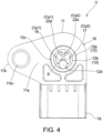
- FIG. 3 shows the sensor unit according to one embodiment, and is an external perspective view as viewed from a joint surface side of the case joined to an intake pipe.
- FIG. 4 shows the sensor unit according to one embodiment, and is a plan view of the joint surface of the case joined to the intake pipe.
- FIG. 5 is a partial cross-sectional view showing a state in which the sensor unit according to one embodiment is attached to the intake pipe.
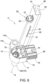
- FIG. 6 is an exploded perspective view of the sensor unit according to one embodiment, as viewed from one side.
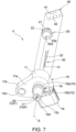
- FIG. 7 is an exploded perspective view of the sensor unit according to one embodiment, as viewed from the other side.
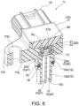
- FIG. 8 is a perspective cross-sectional view of the sensor unit according to one embodiment, taken along a plane passing through a center line of a first ventilation hole and a center line of a second ventilation hole.
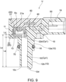
- FIG. 9 is a cross-sectional view of the sensor unit according to one embodiment, taken along a plane including a center line of a first passage forming a first communication path and the center line of the first ventilation hole.
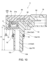
- FIG. 10 is a cross-sectional view of the sensor unit according to one embodiment, taken along a plane including a center line of a second passage forming a second communication path and the center line of the second ventilation hole.
- FIG. 11 is a perspective cross-sectional view of a pressure sensor (sensor body, sensor cover) in the sensor unit according to one embodiment.
- FIG. 12 is an exploded perspective view of a sensor body and a sensor cover that constitute the pressure sensor in the sensor unit according to one embodiment.
- FIG. 13 is a cross-sectional view showing a temperature sensor accommodated in a second accommodation part in the sensor unit according to one embodiment.
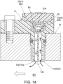
- FIG. 14 is a schematic diagram describing a flow of intake air in a communication path (first communication path including first passage and first ventilation hole, and second communication path including second passage and second ventilation hole) that provides communication between a pressure receiving chamber and an intake passage in the sensor unit according to one embodiment.
- FIG. 15 is a schematic diagram describing a flow of intake air in the communication path (first communication path including first passage and first ventilation hole, and second communication path including second passage and second ventilation hole) that provides communication between the pressure receiving chamber and the intake passage in a sensor unit according to another embodiment.
- FIG. 16 is a schematic diagram describing a flow of intake air in the communication path (first communication path, second communication path) that provides communication between the pressure receiving chamber and the intake passage in a sensor unit according to still another embodiment.
- Hereinafter, embodiments of the present disclosure will be described with reference to the accompanying drawings.
- A sensor unit U of the present disclosure is incorporated into, for example, an intake system of an internal combustion engine E mounted on a vehicle such as an automobile or a motorcycle.
- The internal combustion engine E includes: a
cylinder block 1; apiston 2; acylinder head 3; anintake valve 4a, opening and closing anintake port 3a; anexhaust valve 4b, opening and closing anexhaust port 3b; aspark plug 5; acam mechanism 6, driving theintake valve 4a and theexhaust valve 4b; and so on. - The intake system of the internal combustion engine E includes: an intake pipe Ip, connected to the
cylinder head 3 in order to lead to theintake port 3a; a throttle device M, connected to the middle of the intake pipe Ip; an air cleaner Ac, connected to an upstream end of the intake pipe Ip; a fuel injection valve Iv, arranged downstream of the intake pipe Ip; the sensor unit U, arranged downstream of the throttle device M and upstream of the fuel injection valve Iv in the intake pipe Ip; and so on. - The intake pipe Ip defines an intake passage Ipi that guides intake air to a combustion chamber C of the internal combustion engine E.
- The throttle device M includes: a butterfly-type throttle valve m1, opening and closing the intake passage Ipi; a bypass passage m2, bypassing the throttle valve m1; and so on.
- An exhaust system of the internal combustion engine E includes: an exhaust pipe Ep, connected to the
cylinder head 3 in order to lead to theexhaust port 3b; a catalytic converter Cc and an oxygen sensor Os, arranged in the middle of the exhaust pipe Ep; and so on. - As shown in
FIG. 2 to FIG. 13 , the sensor unit U according to one embodiment includes acase 10, apressure sensor 20, atemperature sensor 30, acircuit board 40, a plurality ofterminals 50, amold resin material 60, and anannular seal member 70. - The
case 10 is molded using a resin material. Thecase 10 includes acase body 11, asleeve 12 of a cylindrical shape, afirst accommodation part 13, asecond accommodation part 14, athird accommodation part 15, afirst passage 16, asecond passage 17, anannular groove 18, and aconnector 19. - As shown in
FIG. 3 andFIG. 5 , thecase body 11 includes: a flatjoint surface 11a, joined to an outer wall of the intake pipe Ip; and aflange 11b, including acircular hole 11b1 through which a fastening screw (not shown) that is screwed into a screw hole in the intake pipe Ip passes. - The
sleeve 12 is formed in a two-step cylindrical shape extending in a direction of an axis S perpendicular to thejoint surface 11a of thecase body 11. That is, thesleeve 12 is formed to include a large-diametercylindrical part 12a, and a small-diametercylindrical part 12b continuous with the large-diametercylindrical part 12a. - As shown in
FIG. 5 , with the sensor unit U assembled to the intake pipe Ip, the large-diametercylindrical part 12a is fitted into a fitting hole H of the intake pipe Ip, and the small-diametercylindrical part 12b is arranged in a slightly protruding manner within the intake passage Ipi of the intake pipe Ip. - As shown in
FIG. 6 andFIG. 8 toFIG. 10 , thefirst accommodation part 13 is a region where thepressure sensor 20 is accommodated and held, and is formed in an inside region of thecase body 11. - As shown in
FIG. 13 , thesecond accommodation part 14 is a region where thetemperature sensor 30 is accommodated. Thesecond accommodation part 14 is formed in a region obtained by extending an inside region of thesleeve 12 from the inside region of thecase body 11 to the inside of a tipouter wall 12d of a semi-spherical shape that defines an outer wall protruding from anend face 12c of thesleeve 12. - As shown in
FIG. 6 , thethird accommodation part 15 is a region where thecircuit board 40 is accommodated and held, and is formed in the inside region of thecase body 11. - As shown in
FIG. 8 andFIG. 9 , on the inside of thesleeve 12, thefirst passage 16 is formed to extend linearly in the direction of the axis S from theend face 12c that defines an open end of thesleeve 12 to thefirst accommodation part 13 of thecase body 11, having a predetermined passage length Ls and constant passage area. An open end on the deep side of thefirst passage 16 leads to afirst ventilation hole 22d formed in asensor cover 22 of thepressure sensor 20. - As shown in
FIG. 8 andFIG. 10 , on the inside of thesleeve 12, thesecond passage 17 is formed to extend linearly in the direction of the axis S and be adjacent to thefirst passage 16 from theend face 12c to thefirst accommodation part 13 of thecase body 11, having the same passage length Ls as thefirst passage 16 and the same passage area as that of thefirst passage 16. An open end on the deep side of thesecond passage 17 leads to asecond ventilation hole 22e formed in thesensor cover 22 of thepressure sensor 20. - That is, the
first passage 16 and thesecond passage 17 are formed to have the same passage length Ls and the same passage area. Thefirst passage 16 is formed to provide communication between a pressure receiving chamber Rc of thepressure sensor 20 and the intake passage Ipi of the intake pipe Ip through thefirst ventilation hole 22d. Thesecond passage 17 is formed to provide communication between the pressure receiving chamber Rc of thepressure sensor 20 and the intake passage Ip1 of the intake pipe Ip through thesecond ventilation hole 22e. - As shown in
FIG. 5 ,FIG. 7 , andFIG. 8 , in a region of the large-diametercylindrical part 12a of thesleeve 12 of thecase 10, theannular groove 18 is formed by hollowing out an outer periphery in an annular shape for theannular seal member 70 to be fitted therein. - As shown in
FIG. 9 , theconnector 19 protrudes in a direction perpendicular to the axis S from thecase body 11, and is formed to expose and surround a plurality of (here, four)terminals 50 connected to thecircuit board 40 and to be connected to the outside. - As shown in
FIG. 11 andFIG. 12 , thepressure sensor 20 is composed of asensor body 21 and asensor cover 22. - The
sensor body 21 includes, for example: apressure receiving part 21a, such as a diaphragm including a semiconductor strain gauge; alead wire 21b, extending from thepressure receiving part 21a; and anannular part 21c, surrounding thepressure receiving part 21a. - The
sensor cover 22 includes a bottom 22a of a disk shape, anannular step part 22b, an annularouter wall 22c, thefirst ventilation hole 22d, and thesecond ventilation hole 22e. In order to function as a protective cover that covers thepressure receiving part 21a and to define the pressure receiving chamber Rc, thesensor cover 22 has theannular part 21c fitted into the annularouter wall 22c and is connected to thesensor body 21. - The
pressure sensor 20 outputs, as an electrical signal, a change in electrical resistance according to the amount of deformation in thepressure receiving part 21a due to a pressure of the intake air guided into the pressure receiving chamber Rc through thefirst ventilation hole 22d and thesecond ventilation hole 22e. - While the sensor unit U is assembled to the intake pipe Ip, the
pressure sensor 20 may detect a pressure of the intake air flowing through the intake passage Ipi downstream of the throttle device M. - Here, as shown in
FIG. 9 , thefirst ventilation hole 22d has a passage length Lc corresponding to a wall thickness of the bottom 22a. As shown inFIG. 11 , thefirst ventilation hole 22d constitutes a circular hole having opening area (inner diameter D1) sufficiently smaller than the passage area of thefirst passage 16, and is formed to lead to thefirst passage 16. - As shown in
FIG. 10 , thesecond ventilation hole 22e has the passage length Lc corresponding to the wall thickness of the bottom 22a. As shown inFIG. 11 , thesecond ventilation hole 22e constitutes a circular hole having opening area (inner diameter D2) sufficiently smaller than the passage area of thesecond passage 17 and smaller than the opening area of thefirst ventilation hole 22d (that is, D1>D2), and is formed to lead to thesecond passage 17. - For example, the inner diameter D2 of the
second ventilation hole 22e is 0.6 to 0.7 time the inner diameter D1 of thefirst ventilation hole 22d. Specifically, as an example, D1=1.5 mm and D2=1.0 mm. - The passage length Lc of the
first ventilation hole 22d and thesecond ventilation hole 22e is the same as a plate thickness dimension of the bottom 22a, and is, for example, about 1.0 to 1.7 times the inner diameters D1 and D2. - According to the above configuration, a communication path that provides communication between the pressure receiving chamber Rc of the
pressure sensor 20 and the intake passage Ip1 of the intake pipe Ip is formed to include: a first communication path Cp1, having a predetermined passage length Lo (=Ls+Lc); and a second communication path Cp2, having the same passage length Lo (=Ls+Lc) as the first communication path Cp1 and including a region (second ventilation hole 22e) having passage area smaller than the passage area of the first communication path Cp1. - Specifically, the first communication path Cp1 is formed to include: the
first passage 16, having the predetermined passage length Ls and passage area; and thefirst ventilation hole 22d, leading to thefirst passage 16, having the passage length Lc, and having the opening area smaller than the passage area of thefirst passage 16. The second communication path Cp2 is formed to include: thesecond passage 17, having the same passage length Ls and passage area as thefirst passage 16; and thesecond ventilation hole 22e, leading to thesecond passage 17, having the passage length Lc, and having the opening area smaller than the opening area of thefirst ventilation hole 22d. - Here, since the
first ventilation hole 22d and thesecond ventilation hole 22e are formed to have opening area smaller than the passage area of thefirst passage 16 and thesecond passage 17, thefirst ventilation hole 22d and thesecond ventilation hole 22e act (trap function) to prevent foreign matter or the like mixed in with the intake air from entering the pressure receiving chamber Re. - In particular, as shown in
FIG. 11 , thefirst ventilation hole 22d and thesecond ventilation hole 22e are formed offset by a distance Cd in a side part outside a central region including a center line CL of the pressure receiving chamber Rc. - Accordingly, even if foreign matter or the like enters the pressure receiving chamber Rc through the
first ventilation hole 22d and thesecond ventilation hole 22e, it is possible to prevent the foreign matter or the like from directly colliding with thepressure receiving part 21a, the influence of pressure due to impact from the foreign matter or the like or dynamic pressure according to flow velocity of intake air can be suppressed or prevented, and the pressure can be detected with high accuracy. - The
second ventilation hole 22e is formed to have the opening area (inner diameter D2) smaller than the opening area (inner diameter D1) of thefirst ventilation hole 22d. - In general, when pressure loss corresponding to passage resistance is ΔP (Pa), a friction coefficient of a passage is λ (dimensionless), a passage length is L (m), an inner diameter of the passage is D (m), fluid density is ρ (kg/m3) and flow velocity is V (m/s), ΔP=λLρV2/2D is achieved. That is, the pressure loss ΔP is inversely proportional to the inner diameter D of the passage and proportional to the passage length L. Accordingly, when the passage area or the opening area decreases, the pressure loss increases. That is, the passage resistance increases, making it difficult for a fluid to flow.
- Here, when the inner diameter of the
first ventilation hole 22d is D1 and the passage length of thefirst ventilation hole 22d is L1, the inner diameter of thesecond ventilation hole 22e is D2 and the passage length of thesecond ventilation hole 22e is L2, Lc=L2=L1 and D2<D1. Thus, pressure loss ΔP2 of thesecond ventilation hole 22e is greater than pressure loss ΔP1 of thefirst ventilation hole 22d (ΔP2>ΔP1). That is, thesecond ventilation hole 22e is formed so as to have greater passage resistance greater than thefirst ventilation hole 22d. - Accordingly, the passage resistance (pressure loss) of the second communication path Cp2 leading to the pressure receiving chamber Rc through the
second passage 17 and thesecond ventilation hole 22e is greater than the passage resistance (pressure loss) of the first communication path Cp1 leading to the pressure receiving chamber Rc through thefirst passage 16 and thefirst ventilation hole 22d. - According to the above configuration, in the vicinity of the
end face 12c of thesleeve 12, in the case where a negative pressure occurs as thepiston 2 is lowered, with the pressure receiving chamber Rc as the starting point, a trigger flow is generated that is drawn out from the first communication path Cp1 having small passage resistance into the intake passage Ipi, and a follow-up flow is accordingly generated that flows from the intake passage Ip1 through the second communication path Cp2 into the pressure receiving chamber Rc. - Accordingly, in the sensor unit U, by generating an intake air flow in a communication path (first communication path Cp1 and second communication path Cp2), it can be suppressed or prevented that a liquid or liquid-like substance such as fuel, moisture in intake air, and blow-by gas adheres to the inside of the communication path, and freezing of adhered substances or the like can be prevented. Hence, the
pressure sensor 20 is able to detect with high accuracy the pressure of the intake air guided to the pressure receiving chamber Rc. - Here, the first communication path Cp1 and the second communication path Cp2 open to the intake passage Ipi in positions adjacent to each other, that is, the
first passage 16 and thesecond passage 17 are formed to open while being adjacent to each other at an open end (endface 12c) of thesleeve 12. - Accordingly, pressure atmospheres at the open ends of the first communication path Cp1 and the second communication path Cp2 become equal. Thus, a difference between the passage resistance (pressure loss) of the first communication path Cp1 and the passage resistance (pressure loss) of the second communication path Cp2 can be easily determined simply by a difference (difference in opening area) between the
first ventilation hole 22d and thesecond ventilation hole 22e. - Since the
first ventilation hole 22d and thesecond ventilation hole 22e are formed as circular holes, desired passage resistance (pressure loss) can be easily set by calculation in comparison with the case of irregularly shaped holes. - When the
case 10 is molded from a resin material using a die, thepressure sensor 20 having the above configuration is arranged in the die and molded integrally so as to be accommodated in thefirst accommodation part 13 of thecase body 11. Thepressure sensor 20 has thelead wire 21b electrically connected to thecircuit board 40, and then is covered and sealed with themold resin material 60. - The
pressure sensor 20 may, in a later process, be fitted into thefirst accommodation part 13 of thecase 10 that has been molded in advance from a resin material, and be sealed with themold resin material 60. - As shown in
FIG. 6 ,FIG. 7 , andFIG. 13 , thetemperature sensor 30 is a reed-type sensor, and is composed of, for example, atemperature sensing element 31 such as a thermistor, and alead wire 32 extending from thetemperature sensing element 31. That is, thetemperature sensor 30 is inserted into thesecond accommodation part 14 of thecase 10, has thetemperature sensing element 31 arranged in an inside region of the tipouter wall 12d of thesleeve 12, has thelead wire 32 electrically connected to thecircuit board 40, and is then covered and sealed with themold resin material 60. - While the sensor unit U is assembled to the intake pipe Ip, the
temperature sensor 30 may detect a temperature of the intake air flowing through the intake passage Ipi downstream of the throttle device M. - The
circuit board 40 has printed wiring and various electronic components (not shown) mounted on its surface. As shown inFIG. 6 andFIG. 7 , thecircuit board 40 includes three throughholes 41 to which thelead wire 21b of thepressure sensor 20 is electrically connected, and four throughholes 42 to which thelead wire 32 of thetemperature sensor 30 is electrically connected. - During assembly, the
circuit board 40 is arranged in thethird accommodation part 15 of thecase body 11, having thelead wires mold resin material 60. - The terminal 50 is made of a conductive metal material. As shown in
FIG. 9 andFIG. 10 , the terminal 50 is embedded in thecase body 11, has one end connected to the throughhole 42 of thecircuit board 40, and is arranged to have its free end side exposed inside theconnector 19 and surrounded by theconnector 19. - The
mold resin material 60 is a sealing material such as epoxy resin. With thepressure sensor 20, thetemperature sensor 30, and thecircuit board 40 accommodated and held in thefirst accommodation part 13, thesecond accommodation part 14, and thethird accommodation part 15 of thecase 10, respectively, themold resin material 60 is injected into thecase 10 to fill gaps and spaces and is solidified. - Accordingly, as shown in
FIG. 8 ,FIG. 9 ,FIG. 10 , andFIG. 13 , thefirst accommodation part 13, thesecond accommodation part 14, and thethird accommodation part 15, with thepressure sensor 20, thetemperature sensor 30, and thecircuit board 40 respectively arranged therein, are sealed by filling themold resin material 60. - The
annular seal member 70 is made of a rubber material excellent in heat resistance, swelling resistance and so on. As shown inFIG. 13 andFIG. 14 , theannular seal member 70 is formed in an annular shape, and is fitted into theannular groove 18 formed on the outer periphery of thesleeve 12 of thecase 10. - As shown in
FIG. 5 , theannular seal member 70 seals between the fitting hole H of the intake pipe Ip and thesleeve 12 while the sensor unit U is assembled to the intake pipe Ip. - Next, in the internal combustion engine E equipped with the sensor unit U, a detection operation of the sensor unit U will be described.
- First, when the internal combustion engine E is in an idle operating range, the throttle valve m1 has closed the intake passage Ipi. The intake air flowing through the intake passage Ip1 flows through the bypass passage m2 so as to bypass the throttle valve m1, and then flows out again into the intake passage Ipi on the downstream side.
- On the other hand, when the internal combustion engine E is in an operating range other than the idle operating range, the throttle valve m1 is in a predetermined opening degree range and has opened the intake passage Ipi.
- Accordingly, the intake air flowing through the intake passage Ipi flows through the intake passage Ipi and is drawn into the internal combustion engine E, without passing through the bypass passage m2.
- In an operating state of the internal combustion engine E, a pressure and a temperature, which are state quantities of the intake air, are detected by the sensor unit U downstream of the throttle device M.
- That is, the temperature of the intake air is detected by the
temperature sensor 30. Specifically, since thetemperature sensing element 31 is arranged in the vicinity of the inside of the tipouter wall 12d protruding from theend face 12c of thesleeve 12, the temperature of the intake air flowing through the intake passage Ipi may be detected in a region away from a wall surface of the intake pipe Ip. Accordingly, the influence of the temperature of the wall surface of the intake pipe Ip can be suppressed. - By the
pressure sensor 20, the pressure of the intake air flowing through the intake passage Ipi through the first communication path Cp1 including thefirst passage 16 and thefirst ventilation hole 22d and the second communication path Cp2 including thesecond passage 17 and thesecond ventilation hole 22e is detected. - Specifically, when comparing the case of flow between the first communication path Cp1 and the second communication path Cp2, since the second communication path Cp2 includes the
second ventilation hole 22e having large passage resistance (pressure loss), flowing is facilitated in the first communication path Cp1 than in the second communication path Cp2. - Accordingly, as shown in
FIG. 14 , the intake air in the pressure receiving chamber Rc is drawn out into the intake passage Ipi through the first communication path Cp1. In conjunction with this flow of intake air, the intake air in the intake passage Ipi flows into the pressure receiving chamber Rc through the second communication path Cp2. - By continuous execution of this flow, the intake air is supplied into the pressure receiving chamber Rc, and the pressure of the intake air is detected by the
pressure receiving part 21a. By this flow of intake air, it can be suppressed or prevented that a liquid or liquid-like substance such as fuel, moisture in intake air, and blow-by gas adheres to an inner wall surface of the first communication path Cp1 and the second communication path Cp2. Hence, freezing of the liquid or liquid-like substance can be suppressed or prevented. By thefirst ventilation hole 22d and thesecond ventilation hole 22e, foreign matter or the like can be prevented from entering the pressure receiving chamber Rc. - In this way, the pressure of the intake air is detected by the
pressure sensor 20, and the temperature of the intake air is detected by thetemperature sensor 30. The information respectively detected is incorporated as control information to an ECU, and the internal combustion engine E is appropriately controlled. - As described above, the sensor unit U is configured to include: the
pressure sensor 20, detecting the pressure of the intake air in the intake pipe Ip; and thecase 10, including thefirst accommodation part 13 and a communication path, thefirst accommodation part 13 accommodating thepressure sensor 20, the communication path providing communication between the pressure receiving chamber Rc of thepressure sensor 20 and the intake passage Ipi of the intake pipe Ip. The communication path is configured to include the first communication path Cp1 and the second communication path Cp2, the first communication path Cp1 having the predetermined passage length Lo, the second communication path Cp2 having the same passage length Lo as the first communication path Cp1 and including a region (second ventilation hole 22e) having passage area smaller than the passage area of the first communication path Cp1. - According to this, the passage resistance (pressure loss) of the second communication path Cp2 is greater than the passage resistance (pressure loss) of the first communication path Cp1. In comparison with the second communication path Cp2, in the first communication path Cp1, it is likely to generate a flow of intake air from the pressure receiving chamber Rc toward the intake passage Ipi. That is, since a trigger flow is generated in the first communication path Cp1, a flow is also generated in the second communication path Cp2 in conjunction with the trigger flow, and a flow is generated in the whole communication path.
- Accordingly, in the regions of the first communication path Cp1, the pressure receiving chamber Rc, and the second communication path Cp2, stagnation of an intake air flow can be suppressed or prevented.
- Hence, with respect to the pressure receiving chamber Rc, the intake air in the intake passage Ipi can be constantly supplied, entry of foreign matter can be suppressed or prevented, adhesion or freezing of a liquid or liquid-like substance such as fuel, moisture in intake air, and blow-by gas can be suppressed or prevented, and the pressure of the intake air can be detected with high accuracy by the
pressure receiving part 21a. - In the above embodiment, as shown in
FIG. 5 andFIG. 14 , theend face 12c of thesleeve 12 of the sensor unit U is shown in the form of being attached so as to slightly protrude from an inner wall surface of the intake pipe Ip. However, the present disclosure is not limited thereto. - For example, the following form may be adopted. As shown in
FIG. 15 , theend face 12c of thesleeve 12 of the sensor unit U is arranged to protrude toward the center of the intake passage Ipi. - In general, the flow velocity of the intake air in the intake passage Ipi varies depending on the location. For example, the flow velocity increases in a central region and decreases in the vicinity of a wall surface. Since the first communication path Cp1 and the second communication path Cp2 open at the
same end face 12c while being adjacent to each other, without being affected by the flow velocity, that is, the pressure, which depends on the location in the intake passage Ipi, an intake air flow can be generated only by a difference in passage resistance (pressure loss) between the first communication path Cp1 and the second communication path Cp2. - In the above embodiment, as a form in which a communication path includes a first communication path that has a predetermined passage length and a second communication path that has the same passage length as the first communication path and includes a region having passage area smaller than passage area of the first communication path, the following form is shown. The communication path includes the first communication path Cp1 and the second communication path Cp2, the first communication path Cp1 including the
first passage 16 that has the predetermined passage area and thefirst ventilation hole 22d that leads to thefirst passage 16 and has the opening area smaller than the passage area of thefirst passage 16, the second communication path Cp2 including thesecond passage 17 that has the same passage length Ls and passage area as thefirst passage 16, and thesecond ventilation hole 22e that leads to thesecond passage 17 and has the opening area smaller than the opening area of thefirst ventilation hole 22d. However, the present disclosure is not limited thereto. - For example, the following form may be adopted. As shown in
FIG. 16 , afirst ventilation hole 122d and asecond ventilation hole 122e are formed to have the same opening area. In the middle of thesecond passage 17, a region Pa is formed having passage area smaller than the passage area (here, passage area offirst passage 16 and opening area offirst ventilation hole 122d) of the first communication path Cp1. - In this form, similarly to the above, the passage resistance (pressure loss) of the second communication path Cp2 is greater than the passage resistance (pressure loss) of the first communication path Cp1. In the first
communication path Cp 1, a trigger flow is generated that is drawn out from the pressure receiving chamber Rc into the intake passage Ipi; in the second communication path Cp2, a follow-up flow is generated that flows from the intake passage Ipi into the pressure receiving chamber Rc. - In the above embodiment, as the first ventilation hole and the second ventilation hole, the
first ventilation hole 22d and thesecond ventilation hole 22e formed in thesensor cover 22 are shown. However, the present disclosure is not limited thereto. A first ventilation hole and a second ventilation hole formed within a sleeve of a case may be adopted. - For example, the first ventilation hole may be provided at a position that divides the first passage in half, and the second ventilation hole may be provided at a position that divides the second passage in half.
- As the first ventilation hole and the second ventilation hole, the
first ventilation hole 22d and thesecond ventilation hole 22e being circular holes are shown. However, a first ventilation hole and a second ventilation hole in a form other than a circular hole may be adopted if the pressure loss of the second ventilation hole is greater than the pressure loss of the first ventilation hole. - In the above embodiment, the first communication path Cp1 and the second communication path Cp2 open to the intake passage Ipi in positions adjacent to each other, that is, the
first passage 16 and thesecond passage 17 are formed to open while being adjacent to each other at an open end (endface 12c) of thesleeve 12. However, the present disclosure is not limited thereto. Other forms may be adopted if a difference in passage resistance (pressure loss) between the first communication path and the second communication path can be set without being affected by a flow velocity (pressure) distribution within the intake passage Ipi. - In the above embodiment, the sensor unit U includes, in addition to the
pressure sensor 20, thetemperature sensor 30 and thecircuit board 40 that electrically connects thepressure sensor 20 and thetemperature sensor 30. However, the present disclosure is not limited thereto. A sensor unit may be adopted in which thetemperature sensor 30 is disused, and thecircuit board 40 and thepressure sensor 20 are provided. Alternatively, a sensor unit may be adopted in which thetemperature sensor 30 and thecircuit board 40 are disused, and only thepressure sensor 20 is provided. - In the above embodiment, as a portion of the first communication path and the second communication path that provide communication between the pressure receiving chamber Rc of the
pressure sensor 20 and the intake passage Ipi of the intake pipe Ip, the sensor unit U is shown which includes thesleeve 12 forming thefirst passage 16 and thesecond passage 17. However, the present disclosure is not limited thereto. A sensor unit equipped with a case including any other form than a sleeve may be adopted if the configuration includes the first communication path and the second communication path. - In the above embodiment, as a cylindrical sleeve protruding in the direction of the axis S from the
case body 11, thesleeve 12 of a two-step cylindrical shape including the large-diametercylindrical part 12a and the small-diametercylindrical part 12b is shown. However, the present disclosure is not limited thereto. A cylindrical sleeve having the same outer diameter may be adopted. - In the above embodiment, as the pressure sensor, the
pressure sensor 20 equipped with a semiconductor strain gauge is shown. However, the present disclosure is not limited thereto. A capacitance-type pressure sensor may be adopted, or a pressure sensor of any other type and forms may be adopted if including a pressure receiving part that receives the pressure of the intake air. - In the above embodiment, as the pressure sensor, the
pressure sensor 20 including thesensor body 21 and thesensor cover 22 is shown. However, the present disclosure is not limited thereto. A pressure sensor without a sensor cover and with a pressure receiving part exposed to the outside may be adopted. In a first accommodation part in which the pressure sensor is accommodated, a pressure receiving chamber may be defined by the pressure sensor in cooperation with an inner wall surface of the first accommodation part of a case. - As described above, in the sensor unit of the present disclosure, entry of foreign matter can be suppressed or prevented, adhesion or freezing of a liquid or liquid-like substance such as fuel, moisture in intake air, and blow-by gas can be suppressed or prevented, and a state quantity (pressure, temperature) of the intake air can be detected with high accuracy. Thus, of course, the sensor unit of the present disclosure is applicable to an intake system of an internal combustion engine in an automobile, a motorcycle or the like, and is also useful in an internal combustion engine of any other vehicle.
-
- E: internal combustion engine
- C: combustion chamber
- Ip: intake pipe
- Ip1: intake passage
- Ac: air cleaner
- M: throttle device
- U: sensor unit
- 10: case
- 11: case body
- 11a: joint surface
- 12: sleeve
- S: axis
- 12a: large-diameter cylindrical part
- 12b: small-diameter cylindrical part
- 12c: end face
- 12d: tip outer wall
- 13: first accommodation part
- 14: second accommodation part
- 15: third accommodation part
- Cp1: first communication path
- Cp2: second communication path
- Lo: passage length of first communication path, passage length of second communication path
- 16: first passage (first communication path)
- 17: second passage (second communication path)
- Ls: passage length of first passage, passage length of second passage
- 18: annular groove
- 19: connector
- 20: pressure sensor
- Rc: pressure receiving chamber 21: sensor body
- 21a: pressure receiving part
- 21b: lead wire
- 21c: annular part
- 22: sensor cover
- 22a: bottom
- 22b: annular step part
- 22c: annular outer wall
- 22d: first ventilation hole (first communication path)
- D1: inner diameter of first ventilation hole
- 22e: second ventilation hole (second communication path)
- D2: inner diameter of second ventilation hole
- 30: temperature sensor
- 31: temperature sensing element
- 32: lead wire
- 40: circuit board
- 50: terminal
- 60: mold resin material
- 70: annular seal member
Claims (18)
- A sensor unit (U), arranged in an intake pipe (Ip) of an internal combustion engine (E), characterized by comprising:a pressure sensor (20), detecting a pressure of intake air in the intake pipe (Ip); anda case (10), comprising a first accommodation part (13) and a communication path, the first accommodation part (13) accommodating the pressure sensor (20), the communication path providing communication between a pressure receiving chamber (Rc) of the pressure sensor (20) and an intake passage (Ipi) of the intake pipe (Ip), whereinthe communication path comprises a first communication path (Cp1) and a second communication path (Cp2), the first communication path (Cp1) having a predetermined passage length (Lo), the second communication path (Cp2) having the same passage length (Lo) as the first communication path (Cp1) and comprising a region having passage area smaller than passage area of the first communication path (Cp1).
- The sensor unit (U) as claimed in claim 1, whereinthe first communication path (Cp1) comprises a first passage (16) and a first ventilation hole (22d), the first passage (16) having predetermined passage area, the first ventilation hole (22d) leading to the first passage (16) and having opening area smaller than the passage area of the first passage (16); andthe second communication path (Cp2) comprises a second passage (17) and a second ventilation hole (22e), the second passage (17) having the same passage length (Ls) and passage area as the first passage (16), the second ventilation hole (22e) leading to the second passage (17) and having opening area smaller than the opening area of the first ventilation hole (22d).
- The sensor unit (U) as claimed in claim 2, whereinthe first ventilation hole (22d) and the second ventilation hole (22e) are formed as circular holes; andan inner diameter (D2) of the second ventilation hole (22e) is smaller than an inner diameter (D1) of the first ventilation hole (22d).
- The sensor unit (U) as claimed in claim 1, wherein
the first communication path (Cp1) and the second communication path (Cp2) are formed to open to the intake passage (Ipi) in positions adjacent to each other. - The sensor unit (U) as claimed in claim 2, whereinthe pressure sensor (20) comprises a sensor body (21) and a sensor cover (22), the sensor body (21) comprising a pressure receiving part (21a), the sensor cover (22) being connected to the sensor body (21) to cover the pressure receiving part (21a) and define the pressure receiving chamber (Rc); andthe first ventilation hole (22d) and the second ventilation hole (22e) are formed in the sensor cover (22).
- The sensor unit (U) as claimed in claim 2, wherein
the first ventilation hole (22d) and the second ventilation hole (22e) are formed in an offset manner close to a side part outside a central region of the pressure receiving chamber (Rc). - The sensor unit (U) as claimed in claim 2, whereinthe case (10) comprises a case body (11) and a sleeve (12), the case body (11) comprising a joint surface (11a) joined to the intake pipe (Ip), the sleeve (12) having a cylindrical shape protruding in a predetermined axis (S) direction from the case body (11); andthe first passage (16) and the second passage (17) are formed to extend within the sleeve (12).
- The sensor unit (U) as claimed in claim 7, wherein
the first passage (16) and the second passage (17) are formed to be adjacent to each other at an open end of the sleeve (12) and to open to the intake passage (Ipi). - The sensor unit (U) as claimed in claim 2, comprising:a temperature sensor (30), detecting a temperature of the intake air in the intake pipe (Ip), whereinthe case (10) comprises a second accommodation part (14) that accommodates the temperature sensor (30).
- The sensor unit (U) as claimed in claim 9, whereinthe case (10) comprises a case body (11) and a sleeve (12), the case body (11) comprising a joint surface (11a) joined to the intake pipe (Ip), the sleeve (12) having a cylindrical shape protruding in a predetermined axis (S) direction from the case body (11); andthe first passage (16), the second passage (17), and the second accommodation part (14) are formed to extend within the sleeve (12).
- The sensor unit (U) as claimed in claim 10, wherein
the sleeve (12) comprises an end face (12c) and a tip outer wall (12d), the end face (12c) being where the first passage (16) and the second passage (17) open to the intake passage (Ipi), the tip outer wall (12d) being formed to protrude from the end face (12c) and defining an outer wall of the second accommodation part (14). - The sensor unit (U) as claimed in claim 9, comprising:a circuit board (40), to which the pressure sensor (20) and the temperature sensor (30) are electrically connected, whereinthe case (10) comprises a third accommodation part (15) that accommodates the circuit board (40).
- The sensor unit (U) as claimed in claim 12, wherein
the first accommodation part (13), the second accommodation part (14), and the third accommodation part (15), with the pressure sensor (20), the temperature sensor (30), and the circuit board (40) respectively arranged therein, are sealed by filling a mold resin material (60). - The sensor unit (U) as claimed in claim 13, wherein
the case (10) comprises a connector (19) that exposes and surrounds a plurality of terminals (50) connected to wiring on the circuit board (40) and is connected to the outside. - The sensor unit (U) as claimed in claim 1, wherein
the case (10) comprises a case body (11), a sleeve (12), and an annular groove (18), the case body (11) comprising a joint surface (11a) joined to the intake pipe (Ip), the sleeve (12) having a cylindrical shape protruding in a predetermined axis (S) direction from the case body (11), the annular groove (18) being formed on an outer periphery of the sleeve (12) and allowing an annular seal member (70) to be fitted therein. - The sensor unit (U) as claimed in claim 15, whereinthe sleeve (12) comprises a large-diameter cylindrical part (12a) continuous with the joint surface (11a) and a small-diameter cylindrical part (12b) continuous with the large-diameter cylindrical part (12a); andthe annular groove (18) is formed in the large-diameter cylindrical part (12a).
- An intake system of an internal combustion engine (E), characterized by comprising:an intake pipe (Ip), defining an intake passage (Ipi) that guides intake air to a combustion chamber (C) of the internal combustion engine (E);a fuel injection valve (Iv), injecting fuel to middle of the intake passage (Ipi) or to the combustion chamber (C);a throttle device (M), provided in middle of the intake pipe (Ip), opening and closing the intake passage (Ipi); anda sensor unit (U), detecting a state quantity of the intake air, whereinthe sensor unit (U) is the sensor unit (U) as claimed in any one of claims 1 to 16.
- The intake system of an internal combustion engine (E) as claimed in claim 17, wherein
the sensor unit (U) is arranged in the intake pipe (Ip) downstream of the throttle device (M).
Applications Claiming Priority (1)
| Application Number | Priority Date | Filing Date | Title |
|---|---|---|---|
| JP2023184478A JP2025073563A (en) | 2023-10-27 | 2023-10-27 | Sensor unit and intake system of internal combustion engine |
Publications (1)
| Publication Number | Publication Date |
|---|---|
| EP4545780A1 true EP4545780A1 (en) | 2025-04-30 |
Family
ID=92538814
Family Applications (1)
| Application Number | Title | Priority Date | Filing Date |
|---|---|---|---|
| EP24196130.9A Pending EP4545780A1 (en) | 2023-10-27 | 2024-08-23 | Sensor unit and intake system of internal combustion engine |
Country Status (4)
| Country | Link |
|---|---|
| US (1) | US20250137862A1 (en) |
| EP (1) | EP4545780A1 (en) |
| JP (1) | JP2025073563A (en) |
| CN (1) | CN119900656A (en) |
Citations (6)
| Publication number | Priority date | Publication date | Assignee | Title |
|---|---|---|---|---|
| JPH1130535A (en) | 1997-07-11 | 1999-02-02 | Mitsubishi Electric Corp | Pressure sensor device |
| US20040134282A1 (en) * | 2002-10-23 | 2004-07-15 | Kyutaro Hayashi | Pressure sensor device having temperature sensor |
| US6813952B2 (en) * | 2003-03-19 | 2004-11-09 | Denso Corporation | Pressure sensor device having temperature sensor |
| JP2005274412A (en) | 2004-03-25 | 2005-10-06 | Denso Corp | Temperature sensor integrated pressure sensor device |
| JP2006194683A (en) | 2005-01-12 | 2006-07-27 | Denso Corp | Temperature sensor integrated pressure sensor device |
| US20080148834A1 (en) * | 2006-10-04 | 2008-06-26 | Mitsubishi Electric Corporation | Detection apparatus and engine control unit |
-
2023
- 2023-10-27 JP JP2023184478A patent/JP2025073563A/en active Pending
-
2024
- 2024-08-01 CN CN202411047473.7A patent/CN119900656A/en active Pending
- 2024-08-08 US US18/797,549 patent/US20250137862A1/en active Pending
- 2024-08-23 EP EP24196130.9A patent/EP4545780A1/en active Pending
Patent Citations (6)
| Publication number | Priority date | Publication date | Assignee | Title |
|---|---|---|---|---|
| JPH1130535A (en) | 1997-07-11 | 1999-02-02 | Mitsubishi Electric Corp | Pressure sensor device |
| US20040134282A1 (en) * | 2002-10-23 | 2004-07-15 | Kyutaro Hayashi | Pressure sensor device having temperature sensor |
| US6813952B2 (en) * | 2003-03-19 | 2004-11-09 | Denso Corporation | Pressure sensor device having temperature sensor |
| JP2005274412A (en) | 2004-03-25 | 2005-10-06 | Denso Corp | Temperature sensor integrated pressure sensor device |
| JP2006194683A (en) | 2005-01-12 | 2006-07-27 | Denso Corp | Temperature sensor integrated pressure sensor device |
| US20080148834A1 (en) * | 2006-10-04 | 2008-06-26 | Mitsubishi Electric Corporation | Detection apparatus and engine control unit |
Also Published As
| Publication number | Publication date |
|---|---|
| CN119900656A (en) | 2025-04-29 |
| JP2025073563A (en) | 2025-05-13 |
| US20250137862A1 (en) | 2025-05-01 |
Similar Documents
| Publication | Publication Date | Title |
|---|---|---|
| US7478560B2 (en) | Sensor apparatus responsive to pressure and temperature within a vessel | |
| EP3232167B1 (en) | Physical quantity detection device | |
| US10655993B2 (en) | Thermal flow meter including a cover mounted on a housing and where a bypass passage is formed by the cover and a bypass passage trench | |
| US10876872B2 (en) | Physical quantity detection device | |
| US9887168B2 (en) | Thermal flow meter | |
| US10168195B2 (en) | Thermal flow meter capable of measuring flow rates in forward flow and reverse flow directions | |
| EP3199924B1 (en) | Thermal flowmeter | |
| EP1790954A2 (en) | Air flow sensor | |
| US10260921B2 (en) | Thermal flow meter | |
| JP6670792B2 (en) | Physical quantity detection device, method for manufacturing physical quantity detection device | |
| US10337899B2 (en) | Thermal flow meter with thin resin portion sealing temperature detection element | |
| US20250137862A1 (en) | Sensor unit and intake system of internal combustion engine | |
| US7096726B2 (en) | Fuel injector system diagnostic system | |
| US11112286B2 (en) | Thermal flowmeter | |
| US20250137882A1 (en) | Sensor unit | |
| US7779809B2 (en) | Throttle system and sensor unit | |
| JP6524017B2 (en) | Thermal flow sensor | |
| JP2025073564A (en) | Sensor unit and intake system of internal combustion engine | |
| US9689358B2 (en) | Air flow measuring device | |
| JP2025099598A (en) | Sensor unit and intake system of internal combustion engine | |
| JPWO2020116034A1 (en) | Physical quantity measuring device | |
| CN202117780U (en) | Sensing unit and engine control system comprising same | |
| US20220349736A1 (en) | Air flow rate measuring device | |
| CN117605580A (en) | throttle device | |
| CN102809461A (en) | Sensor unit and engine control system with same |
Legal Events
| Date | Code | Title | Description |
|---|---|---|---|
| PUAI | Public reference made under article 153(3) epc to a published international application that has entered the european phase |
Free format text: ORIGINAL CODE: 0009012 |
|
| STAA | Information on the status of an ep patent application or granted ep patent |
Free format text: STATUS: THE APPLICATION HAS BEEN PUBLISHED |
|
| AK | Designated contracting states |
Kind code of ref document: A1 Designated state(s): AL AT BE BG CH CY CZ DE DK EE ES FI FR GB GR HR HU IE IS IT LI LT LU LV MC ME MK MT NL NO PL PT RO RS SE SI SK SM TR |
|
| STAA | Information on the status of an ep patent application or granted ep patent |
Free format text: STATUS: REQUEST FOR EXAMINATION WAS MADE |
|
| 17P | Request for examination filed |
Effective date: 20250624 |