EP4545754A1 - Vane outer shroud undercut groove - Google Patents
Vane outer shroud undercut groove Download PDFInfo
- Publication number
- EP4545754A1 EP4545754A1 EP24204543.3A EP24204543A EP4545754A1 EP 4545754 A1 EP4545754 A1 EP 4545754A1 EP 24204543 A EP24204543 A EP 24204543A EP 4545754 A1 EP4545754 A1 EP 4545754A1
- Authority
- EP
- European Patent Office
- Prior art keywords
- groove
- outer shroud
- vane
- vane outer
- rotor blade
- Prior art date
- Legal status (The legal status is an assumption and is not a legal conclusion. Google has not performed a legal analysis and makes no representation as to the accuracy of the status listed.)
- Pending
Links
Images


Classifications
-
- F—MECHANICAL ENGINEERING; LIGHTING; HEATING; WEAPONS; BLASTING
- F01—MACHINES OR ENGINES IN GENERAL; ENGINE PLANTS IN GENERAL; STEAM ENGINES
- F01D—NON-POSITIVE DISPLACEMENT MACHINES OR ENGINES, e.g. STEAM TURBINES
- F01D11/00—Preventing or minimising internal leakage of working-fluid, e.g. between stages
- F01D11/08—Preventing or minimising internal leakage of working-fluid, e.g. between stages for sealing space between rotor blade tips and stator
- F01D11/10—Preventing or minimising internal leakage of working-fluid, e.g. between stages for sealing space between rotor blade tips and stator using sealing fluid, e.g. steam
-
- F—MECHANICAL ENGINEERING; LIGHTING; HEATING; WEAPONS; BLASTING
- F01—MACHINES OR ENGINES IN GENERAL; ENGINE PLANTS IN GENERAL; STEAM ENGINES
- F01D—NON-POSITIVE DISPLACEMENT MACHINES OR ENGINES, e.g. STEAM TURBINES
- F01D11/00—Preventing or minimising internal leakage of working-fluid, e.g. between stages
- F01D11/08—Preventing or minimising internal leakage of working-fluid, e.g. between stages for sealing space between rotor blade tips and stator
-
- F—MECHANICAL ENGINEERING; LIGHTING; HEATING; WEAPONS; BLASTING
- F01—MACHINES OR ENGINES IN GENERAL; ENGINE PLANTS IN GENERAL; STEAM ENGINES
- F01D—NON-POSITIVE DISPLACEMENT MACHINES OR ENGINES, e.g. STEAM TURBINES
- F01D5/00—Blades; Blade-carrying members; Heating, heat-insulating, cooling or antivibration means on the blades or the members
- F01D5/12—Blades
- F01D5/14—Form or construction
- F01D5/141—Shape, i.e. outer, aerodynamic form
- F01D5/142—Shape, i.e. outer, aerodynamic form of the blades of successive rotor or stator blade-rows
- F01D5/143—Contour of the outer or inner working fluid flow path wall, i.e. shroud or hub contour
-
- F—MECHANICAL ENGINEERING; LIGHTING; HEATING; WEAPONS; BLASTING
- F04—POSITIVE - DISPLACEMENT MACHINES FOR LIQUIDS; PUMPS FOR LIQUIDS OR ELASTIC FLUIDS
- F04D—NON-POSITIVE-DISPLACEMENT PUMPS
- F04D29/00—Details, component parts, or accessories
- F04D29/08—Sealings
- F04D29/16—Sealings between pressure and suction sides
- F04D29/161—Sealings between pressure and suction sides especially adapted for elastic fluid pumps
- F04D29/164—Sealings between pressure and suction sides especially adapted for elastic fluid pumps of an axial flow wheel
-
- F—MECHANICAL ENGINEERING; LIGHTING; HEATING; WEAPONS; BLASTING
- F04—POSITIVE - DISPLACEMENT MACHINES FOR LIQUIDS; PUMPS FOR LIQUIDS OR ELASTIC FLUIDS
- F04D—NON-POSITIVE-DISPLACEMENT PUMPS
- F04D29/00—Details, component parts, or accessories
- F04D29/40—Casings; Connections of working fluid
- F04D29/52—Casings; Connections of working fluid for axial pumps
- F04D29/54—Fluid-guiding means, e.g. diffusers
- F04D29/541—Specially adapted for elastic fluid pumps
- F04D29/545—Ducts
- F04D29/547—Ducts having a special shape in order to influence fluid flow
-
- F—MECHANICAL ENGINEERING; LIGHTING; HEATING; WEAPONS; BLASTING
- F04—POSITIVE - DISPLACEMENT MACHINES FOR LIQUIDS; PUMPS FOR LIQUIDS OR ELASTIC FLUIDS
- F04D—NON-POSITIVE-DISPLACEMENT PUMPS
- F04D29/00—Details, component parts, or accessories
- F04D29/66—Combating cavitation, whirls, noise, vibration or the like; Balancing
- F04D29/68—Combating cavitation, whirls, noise, vibration or the like; Balancing by influencing boundary layers
- F04D29/681—Combating cavitation, whirls, noise, vibration or the like; Balancing by influencing boundary layers especially adapted for elastic fluid pumps
- F04D29/685—Inducing localised fluid recirculation in the stator-rotor interface
-
- F—MECHANICAL ENGINEERING; LIGHTING; HEATING; WEAPONS; BLASTING
- F01—MACHINES OR ENGINES IN GENERAL; ENGINE PLANTS IN GENERAL; STEAM ENGINES
- F01D—NON-POSITIVE DISPLACEMENT MACHINES OR ENGINES, e.g. STEAM TURBINES
- F01D5/00—Blades; Blade-carrying members; Heating, heat-insulating, cooling or antivibration means on the blades or the members
- F01D5/12—Blades
- F01D5/14—Form or construction
- F01D5/141—Shape, i.e. outer, aerodynamic form
- F01D5/145—Means for influencing boundary layers or secondary circulations
-
- F—MECHANICAL ENGINEERING; LIGHTING; HEATING; WEAPONS; BLASTING
- F01—MACHINES OR ENGINES IN GENERAL; ENGINE PLANTS IN GENERAL; STEAM ENGINES
- F01D—NON-POSITIVE DISPLACEMENT MACHINES OR ENGINES, e.g. STEAM TURBINES
- F01D9/00—Stators
- F01D9/02—Nozzles; Nozzle boxes; Stator blades; Guide conduits, e.g. individual nozzles
- F01D9/04—Nozzles; Nozzle boxes; Stator blades; Guide conduits, e.g. individual nozzles forming ring or sector
-
- F—MECHANICAL ENGINEERING; LIGHTING; HEATING; WEAPONS; BLASTING
- F05—INDEXING SCHEMES RELATING TO ENGINES OR PUMPS IN VARIOUS SUBCLASSES OF CLASSES F01-F04
- F05D—INDEXING SCHEME FOR ASPECTS RELATING TO NON-POSITIVE-DISPLACEMENT MACHINES OR ENGINES, GAS-TURBINES OR JET-PROPULSION PLANTS
- F05D2250/00—Geometry
- F05D2250/20—Three-dimensional
- F05D2250/29—Three-dimensional machined; miscellaneous
- F05D2250/294—Three-dimensional machined; miscellaneous grooved
Definitions
- Gas turbine engines such as those that power modern commercial and military aircraft and those that are used for land-based power generation, include a compressor section to pressurize a supply of air, a combustor section to burn a fuel in the presence of the pressurized air, and a turbine section to extract energy from the resultant combustion gases to generate thrust or electrical power.
- a major source of gas path leakage in the turbine section is through the shrouded blade tips.
- Gas entering the vane outer shroud tends to radially escape through a gap between the vane outer should and shrouded blade tips.
- the gap provides a path for gas to bypass the airfoils and leak through the blade tips instead of being converted into mechanical work.
- a grooved vane outer shroud for a gas turbine engine is disclosed herein.
- the grooved vane outer shroud includes a vane coupled to the vane outer shroud, an area downstream of the vane through which a rotor blade rotates about an axis relative to the vane, and a groove formed in the vane outer shroud upstream and adjacent to a leading edge of the rotor blade.
- the groove is configured to recirculate air and/or gas radially inward toward the rotor blade.
- the groove is formed radially outward into the vane outer shroud. In various embodiments, the groove is formed in the vane outer shroud upstream and adjacent to a leading edge of a blade shroud of the rotor blade. In various embodiments, a separate groove is formed in the vane outer shroud upstream and adjacent to each leading edge of each rotor blade within a low-pressure turbine section of the gas turbine engine. In various embodiments, a depth of the groove is half of a width of the groove. In various embodiments, a depth of the groove is greater than half of a width of the groove. In various embodiments, the groove is configured to have a shape and wherein the shape is at least one of a semicircular shape, a V shape, or a spiral, hook-shape.
- the gas turbine engine includes a vane, a rotor blade, and a vane outer shroud.
- the vane outer shroud includes the vane coupled to the vane outer shroud, an area downstream of the vane through which the rotor blade rotates about an axis relative to the vane, and a groove formed in the vane outer shroud upstream and adjacent to a leading edge of the rotor blade. The groove is configured to recirculate air and/or gas radially inward toward the rotor blade.
- the groove is formed radially outward into the vane outer shroud. In various embodiments, the groove is formed in the vane outer shroud upstream and adjacent to a leading edge of a blade shroud of the rotor blade. In various embodiments, the gas turbine engine further includes a plurality of rotor blades. In various embodiments, a separate groove is formed in the vane outer shroud upstream and adjacent to each leading edge of each of the plurality of rotor blades within a low-pressure turbine section of the gas turbine engine. In various embodiments, a depth of the groove is half of a width of the groove. In various embodiments, a depth of the groove is greater than half of a width of the groove. In various embodiments, the groove is configured to have a shape and wherein the shape is at least one of a semicircular shape, a V shape, or a spiral, hook-shape.
- the aircraft includes a gas turbine engine,
- the gas turbine engine includes a vane, a rotor blade, and a vane outer shroud.
- the vane outer shroud includes the vane coupled to the vane outer shroud, an area downstream of the vane through which the rotor blade rotates about an axis relative to the vane, and a groove formed in the vane outer shroud upstream and adjacent to a leading edge of the rotor blade.
- the groove is configured to recirculate air and/or gas radially inward toward the rotor blade.
- the present disclosure may include any one or more of the individual features disclosed above and/or below alone or in any combination thereof.
- the foregoing features and elements may be combined in various combinations without exclusivity, unless expressly indicated herein otherwise.
- references to "a,” “an,” or “the” may include one or more than one and that reference to an item in the singular may also include the item in the plural. Further, all ranges may include upper and lower values and all ranges and ratio limits disclosed herein may be combined.
- a grooved vane outer shroud for a gas turbine engine that reduces blade tip leakages for improving turbine efficiency, reducing temperatures, and improving specific fuel consumption.
- the grooved vane outer shroud includes a groove undercut in the vane outer shroud located near the blade tip.
- the groove undercut may be a semicircular groove, a V-shaped groove, or a spiral, hook-shaped groove, among others.
- the grooved undercut may be provided in one or more stages within the turbine section. In various embodiments, the grooved undercut may be provided in all stages of the turbine section.
- a cross sectional view, in an axial direction, a gas turbine engine 20 is illustrated shown according to various embodiments.
- tail refers to the direction associated with the tail (e.g., the back end) of an aircraft, or generally, to the direction of exhaust of the gas turbine engine.
- forward refers to the direction associated with the nose (e.g., the front end) of an aircraft, or generally, to the direction of flight or motion, or to the direction associated with the inlet of the gas turbine engine.
- radially inward refers to the negative R direction (towards axis A-A') and radially outward refers to the R direction (away from the A-A' axis).
- An A-R-C axis is shown in various drawings to illustrate the relative position of various components.
- Gas turbine engine 20 may be a two-spool turbofan that generally incorporates a fan section 22, a compressor section 24, a combustor section 26, and a turbine section 28.
- fan section 22 may drive fluid, i.e. air, along a path of bypass airflow B while compressor section 24 may drive the fluid along a core flow path P for compression and communication into combustor section 26 then expansion through turbine section 28.
- turbofan gas turbine engine 20 depicted as a turbofan gas turbine engine 20 herein, it should be understood that the concepts described herein are not limited to use with turbofans as the teachings may be applied to other types of turbine engines.
- Gas turbine engine 20 may generally include a low-speed spool 40 and a high-speed spool 32 mounted for rotation about an engine central longitudinal axis A-A' relative to an engine static structure 36 or engine case via several bearing systems 38, 38-1, 38-2, etc.
- Engine central longitudinal axis A-A' is oriented in the y- direction on the provided X-Y-Z axes.
- various bearing systems 38 at various locations may alternatively or additionally be provided, including for example, bearing system 38, bearing system 38-1, bearing system 38-2, etc.
- Low-speed spool 40 may generally include an inner shaft 40 that interconnects a fan 42, a low-pressure compressor 44, and a low-pressure turbine 46.
- Inner shaft 40 may be connected to fan 42 through a geared system 48 that may drive the fan 42 at a lower speed than low-speed spool 40.
- Geared system 48 may include a gear assembly enclosed within a gear housing.
- Geared system 48 couples the inner shaft 40 to a rotating fan structure.
- the geared system 48 includes a gear assembly 60 enclosed within a gear housing 62.
- the gear assembly 60 couples the inner shaft 40 to a rotating fan structure.
- High-speed spool 32 may include an outer shaft 50 that interconnects a high-pressure compressor 52 and high-pressure turbine 54.
- a combustor section 56 may be located between high-pressure compressor 52 and high-pressure turbine 54.
- a mid-turbine frame 57 of engine static structure 30 may be located generally between high-pressure turbine 54 and low-pressure turbine 46.
- Mid-turbine frame 57 may support one or more bearing systems 38 in turbine section 28.
- Inner shaft 40 and outer shaft 50 may be concentric and rotate via bearing systems 38 about the engine central longitudinal axis A-A', which is collinear with their longitudinal axes.
- a "high pressure" compressor or turbine experiences a higher pressure than a corresponding "low pressure” compressor or turbine.
- the core airflow may be compressed by low-pressure compressor 44 then high-pressure compressor 52, mixed and burned with fuel in the combustor section 56, then expanded over high-pressure turbine 54 and low-pressure turbine 46.
- the mid-turbine frame 57 includes airfoils 59 which are in the core airflow path C.
- Turbines 46, 54 rotationally drive the respective low-speed spool 40 and high-speed spool 32 in response to the expansion.
- geared system 48 may be varied.
- geared system 48 may be located aft of combustor section 26 or even aft of turbine section 28, and fan section 22 may be positioned forward or aft of the location of geared system 48.
- the gas turbine engine 20, in various embodiments, is a high-bypass geared aircraft engine.
- the gas turbine engine 20 bypass ratio is greater than about six (6), with an example embodiment being greater than about ten (10)
- the geared system 48 is an epicyclic gear train, such as a planetary gear system or other gear system, with a gear reduction ratio of greater than about 2.3
- the low-pressure turbine 46 has a pressure ratio that is greater than about five.
- the gas turbine engine 20 bypass ratio is greater than about ten (10:1)
- the fan diameter is significantly larger than that of the low-pressure compressor 44
- the low-pressure turbine 46 has a pressure ratio that is greater than about five 5: 1.
- Low-pressure turbine 46 pressure ratio is pressure measured prior to inlet of low-pressure turbine 46 as related to the pressure at the outlet of the low-pressure turbine 46 prior to an exhaust nozzle.
- the geared system 48 may be an epicycle gear train, such as a planetary gear system or other gear system, with a gear reduction ratio of greater than about 2.3:1. It should be understood, however, that the above parameters are only exemplary of one embodiment of a geared architecture engine and that the present invention is applicable to other gas turbine engines including direct drive turbofans.
- turbine section 28 includes a plurality of rotor blades 202 and a plurality of vanes 204.
- the first rotor blade 202a and the second rotor blade 202b are each configured to rotate about the axis A-A' relative to first vane 204a and second vane 204b in response to receiving a flow of fluid from the combustor section 26.
- kinetic energy from the flow is converted to mechanical energy, or torque, by the first rotor blade 202a and the second rotor blade 202b.
- Each of the first vane 204a and the second vane 204b are coupled to a frame 206 of the low-pressure turbine 46 via a vane outer shroud 208 and each of the first vane 204a and the second vane 204b condition the flow of air/gas 210 between the first rotor blade 202a and the second rotor blade 202b, respectively.
- the second vane 204b thus acts as a stator and does not rotate relative to the axis A-A'.
- each of the first rotor blade 202a and the second rotor blade 202b include a blade tip 212 coupled to the rotor blade via a blade shroud 211.
- a blade outer air seal (BOAS) 214 is located radially outward from the first rotor blade 202a and the second rotor blade 202b.
- the low-pressure turbine 46 may include multiple BOASs 214 positioned adjacent each other circumferentially and surrounding the longitudinal axis A-A' of FIG. 1 .
- the BOAS 214 are designed to function as a seal to reduce axial leakage of the air/gas 210 between the blade tip 212 of the first rotor blade 202a and the second rotor blade 202b and the frame 206.
- the BOAS 214 has an inner surface that forms a seal along with the blade tip 212 of the first rotor blade 202a and the second rotor blade 202b.
- the core airflow may contact the radially inner surface of the BOAS 214.
- the BOAS 214 are designed to function as a seal to reduce axial leakage of the air/gas 210 between the blade tip 212 of the first rotor blade 202a and the second rotor blade 202b and the frame 206.
- the air/gas 210 gas entering the vane outer shroud 208 still tends to radially escape through a gap between the vane outer should 208 and blade tips 212.
- the gap provides a path for the air/gas 210 to bypass the first rotor blade 202a and the second rotor blade 202b and leak through the blade tips 212 instead of being converted into mechanical work.
- a groove 216 may be formed in the vane outer shroud 208 adjacent a leading edge of the blade tip 212 of a respective one of the first rotor blade 202a and/or the second rotor blade 202b.
- the groove 216 may be formed upstream, i.e. forward in an y-direction of the rotor blade, and circumferentially within the vane outer shroud 208 adjacent a leading edge of the blade shroud 211of the respective one of the first rotor blade 202a and/or the second rotor blade 202b.
- the groove 216 may have a semicircular shape as illustrated in FIG. 3A , a 'V' shape as illustrated in FIG.
- a depth d in the z-direction of the groove 216 into the vane outer shroud 208 is half of the width w of the groove 216, i.e. a ratio of depth d in the z-direction of the groove 216 to the width w of the groove 216 of .5 to 1.
- the depth d in the z-direction of the groove 216 into the vane outer shroud 208 is at greater than half of the width w of the shaped groove. i.e. a ratio of >.5 to 1.
- a greater depth d provides for more recirculation of the air/gas 210 thereby forcing the air/gas radially inward toward the first rotor blade 202a and the second rotor blade 202b thereby tending to increase turbine efficiency, reduce temperatures, and improve specific fuel consumption. That is, by providing the groove 216 in the vane outer shroud 208 located near the blade shroud 211, a local aerodynamic recirculation of air is generated that forms a barrier which discourages the air/gas 210 to leak through the blade tip 212.
- the groove 216 may be provided in one or more stages within the turbine section. In various embodiments, the groove 216 may be provided in all stages of the turbine section.
- the groove 216 may be formed in the vane outer shroud 208 adjacent a leading edge of the blade shroud 211of the first rotor blade 202a.
- the groove 216 has a semicircular shape.
- the groove 216 has a depth d that is half of the width w of the groove 216, i.e.
- the depth d in the z-direction of the groove 216 into the vane outer shroud 208 is at greater than half of the width w of the shaped groove, i.e. a ratio of >.5 to 1.
- maximum depth dto width w ratio may have a maximum depth d otherwise the air/gas 210 may not recirculate properly.
- depth d to width w ratio is less than 5, e.g. d / w ⁇ 5.
- a greater depth d provides for more recirculation of the air/gas 210 thereby forcing the air/gas radially inward toward the first rotor blade 202a thereby tending to increase turbine efficiency, reduce temperatures, and improve specific fuel consumption.
- the groove 216 may be formed in the vane outer shroud 208 adjacent a leading edge of the blade shroud 211of the first rotor blade 202a.
- the groove 216 has a 'V' shape.
- the groove 216 has a depth d that is half of the width w of the groove 216, i.e.
- the depth d in the z-direction of the groove 216 into the vane outer shroud 208 is at greater than half of the width w of the shaped groove, i.e. a ratio of >.5 to 1.
- maximum depth d to width w ratio may have a maximum depth d otherwise the air/gas 210 may not recirculate properly.
- depth d to width w ratio is less than 5, e.g. d / w ⁇ 5.
- the groove 216 may be formed in the vane outer shroud 208 adjacent a leading edge of the blade shroud 211of the first rotor blade 202a.
- the groove 216 has a spiral, hook shape.
- the groove 216 has a depth d that is half of the width w1 of the groove 216, i.e.
- the depth d in the z-direction of the groove 216 into the vane outer shroud 208 is at greater than half of the width w1 of the shaped groove, i.e. a ratio of >.5 to 1.
- maximum depth dto width w ratio may have a maximum depth d otherwise the air/gas 210 may not recirculate properly.
- depth dto width w ratio is less than 5, e.g. d / w ⁇ 5.
- the spiral, hook shaped undercut groove is formed such that a width w2 of the opening of the spiral, hook shaped undercut groove is less than the width w1 of the groove 216.
- the width w2 is between .5 and .75 of width w1 .
- the width w2 is between .55 and .70 of width w1 .
- the width w2 is between .60 and .65 of width w1 .
- a greater depth d provides for more recirculation of the air/gas 210 thereby forcing the air/gas radially inward toward the first rotor blade 202a thereby tending to increase turbine efficiency, reduce temperatures, and improve specific fuel consumption.
- references to "one embodiment,” “an embodiment,” “an example embodiment,” etc. indicate that the embodiment described may include a particular feature, structure, or characteristic, but every embodiment may not necessarily include the particular feature, structure, or characteristic. Moreover, such phrases are not necessarily referring to the same embodiment. Further, when a particular feature, structure, or characteristic is described in connection with an embodiment, it is submitted that it is within the knowledge of one skilled in the art to affect such feature, structure, or characteristic in connection with other embodiments whether or not explicitly described. After reading the description, it will be apparent to one skilled in the relevant art(s) how to implement the disclosure in alternative embodiments.
Landscapes
- Engineering & Computer Science (AREA)
- Mechanical Engineering (AREA)
- General Engineering & Computer Science (AREA)
- Physics & Mathematics (AREA)
- Fluid Mechanics (AREA)
- Turbine Rotor Nozzle Sealing (AREA)
Abstract
A vane outer shroud (208) for a gas turbine engine (20) is disclosed. The vane outer shroud includes a vane (204a, 204b) coupled to the vane outer shroud (208), an area downstream of the vane through which a rotor blade (202) rotates about an axis (A-A') relative to the vane, and a groove (216) formed in the vane outer shroud upstream and adjacent to a leading edge of the rotor blade (202). The groove is configured to recirculate air and/or gas radially inward toward the rotor blade (202).
Description
- The present disclosure relates to components in turbine engines, and more particularly, a vane outer shroud undercut groove.
- Gas turbine engines, such as those that power modern commercial and military aircraft and those that are used for land-based power generation, include a compressor section to pressurize a supply of air, a combustor section to burn a fuel in the presence of the pressurized air, and a turbine section to extract energy from the resultant combustion gases to generate thrust or electrical power.
- A major source of gas path leakage in the turbine section is through the shrouded blade tips. Gas entering the vane outer shroud tends to radially escape through a gap between the vane outer should and shrouded blade tips. In that regard, the gap provides a path for gas to bypass the airfoils and leak through the blade tips instead of being converted into mechanical work.
- A grooved vane outer shroud for a gas turbine engine is disclosed herein. The grooved vane outer shroud includes a vane coupled to the vane outer shroud, an area downstream of the vane through which a rotor blade rotates about an axis relative to the vane, and a groove formed in the vane outer shroud upstream and adjacent to a leading edge of the rotor blade. The groove is configured to recirculate air and/or gas radially inward toward the rotor blade.
- In various embodiments, the groove is formed radially outward into the vane outer shroud. In various embodiments, the groove is formed in the vane outer shroud upstream and adjacent to a leading edge of a blade shroud of the rotor blade. In various embodiments, a separate groove is formed in the vane outer shroud upstream and adjacent to each leading edge of each rotor blade within a low-pressure turbine section of the gas turbine engine. In various embodiments, a depth of the groove is half of a width of the groove. In various embodiments, a depth of the groove is greater than half of a width of the groove. In various embodiments, the groove is configured to have a shape and wherein the shape is at least one of a semicircular shape, a V shape, or a spiral, hook-shape.
- Also disclosed herein is a gas turbine engine. The gas turbine engine includes a vane, a rotor blade, and a vane outer shroud. The vane outer shroud includes the vane coupled to the vane outer shroud, an area downstream of the vane through which the rotor blade rotates about an axis relative to the vane, and a groove formed in the vane outer shroud upstream and adjacent to a leading edge of the rotor blade. The groove is configured to recirculate air and/or gas radially inward toward the rotor blade.
- In various embodiments, the groove is formed radially outward into the vane outer shroud. In various embodiments, the groove is formed in the vane outer shroud upstream and adjacent to a leading edge of a blade shroud of the rotor blade. In various embodiments, the gas turbine engine further includes a plurality of rotor blades. In various embodiments, a separate groove is formed in the vane outer shroud upstream and adjacent to each leading edge of each of the plurality of rotor blades within a low-pressure turbine section of the gas turbine engine. In various embodiments, a depth of the groove is half of a width of the groove. In various embodiments, a depth of the groove is greater than half of a width of the groove. In various embodiments, the groove is configured to have a shape and wherein the shape is at least one of a semicircular shape, a V shape, or a spiral, hook-shape.
- Also disclosed herein is an aircraft. The aircraft includes a gas turbine engine, The gas turbine engine includes a vane, a rotor blade, and a vane outer shroud. The vane outer shroud includes the vane coupled to the vane outer shroud, an area downstream of the vane through which the rotor blade rotates about an axis relative to the vane, and a groove formed in the vane outer shroud upstream and adjacent to a leading edge of the rotor blade. The groove is configured to recirculate air and/or gas radially inward toward the rotor blade.
- In various embodiments, the groove is formed radially outward into the vane outer shroud. In various embodiments, the groove is formed in the vane outer shroud upstream and adjacent to a leading edge of a blade shroud of the rotor blade. In various embodiments, the aircraft further includes a plurality of rotor blades. In various embodiments, a separate groove is formed in the vane outer shroud upstream and adjacent to each leading edge of each of the plurality of rotor blades within a low-pressure turbine section of the gas turbine engine. In various embodiments, a depth of the groove is equal to or greater than half of a width of the groove. In various embodiments, the groove is configured to have a shape and wherein the shape is at least one of a semicircular shape, a V shape, or a spiral, hook-shape.
- The present disclosure may include any one or more of the individual features disclosed above and/or below alone or in any combination thereof. The foregoing features and elements may be combined in various combinations without exclusivity, unless expressly indicated herein otherwise. These features and elements as well as the operation of the disclosed embodiments will become more apparent in light of the following description and accompanying drawings.
- The subject matter of the present disclosure is particularly pointed out and distinctly claimed in the concluding portion of the specification. A more complete understanding of the present disclosure, however, may best be obtained by referring to the detailed description and claims when considered in connection with the drawing figures, wherein like numerals denote like elements.
-
FIG. 1 illustrates a cross-sectional view of a gas-turbine engine, in accordance with various embodiments. -
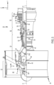
FIG. 2 illustrates an enlarged schematic cross-section of a portion of a low-pressure turbine section of the gas turbine engine ofFIG. 1 , in accordance with various embodiments. -
FIG. 3A illustrates an enlarged section of a vane outer shroud with a semicircular undercut groove to forcibly recirculate air/gas inward toward a rotor blade, in accordance with various embodiments. -
FIG. 3B illustrates an enlarged section of a vane outer shroud with a V-shaped undercut groove to forcibly recirculate air/gas inward toward a rotor blade, in accordance with various embodiments. -
FIG. 3C illustrates an enlarged section of a vane outer shroud with a spiral, hook shaped undercut groove to forcibly recirculate air/gas inward toward a rotor blade, in accordance with various embodiments. - The detailed description of embodiments herein makes reference to the accompanying drawings, which show embodiments by way of illustration. While these embodiments are described in sufficient detail to enable those skilled in the art to practice the disclosure, it should be understood that other embodiments may be realized and that logical, chemical, and mechanical changes may be made without departing from the scope of the disclosure. Thus, the detailed description herein is presented for purposes of illustration only and not for limitation. For example, any reference to singular includes plural embodiments, and any reference to more than one component or step may include a singular embodiment or step. Also, any reference to attached, fixed, connected or the like may include permanent, removable, temporary, partial, full and/or any other possible attachment option. Further, any steps in a method discussed herein may be performed in any suitable order or combination. Additionally, any reference to without contact (or similar phrases) may also include reduced contact or minimal contact. It should also be understood that unless specifically stated otherwise, references to "a," "an," or "the" may include one or more than one and that reference to an item in the singular may also include the item in the plural. Further, all ranges may include upper and lower values and all ranges and ratio limits disclosed herein may be combined.
- As stated previously, gas entering the vane outer shroud tends to radially escape through a gap between the vane outer shroud and shrouded blade tips. In that regard, the gap provides a path for gas to bypass the airfoils and leak through the blade tips instead of being converted into mechanical work. Disclosed herein, in various embodiments, is a grooved vane outer shroud for a gas turbine engine that reduces blade tip leakages for improving turbine efficiency, reducing temperatures, and improving specific fuel consumption. In various embodiments, the grooved vane outer shroud includes a groove undercut in the vane outer shroud located near the blade tip. In various embodiments, the groove undercut may be a semicircular groove, a V-shaped groove, or a spiral, hook-shaped groove, among others. By providing the grooved undercut in the vane outer shroud located near the blade tip, a local aerodynamic recirculation of air is generated that forms a barrier which discourages air to leak through the blade tip. In various embodiments, the grooved undercut may be provided in one or more stages within the turbine section. In various embodiments, the grooved undercut may be provided in all stages of the turbine section.
- With reference to
FIG. 1 , a cross sectional view, in an axial direction, agas turbine engine 20 is illustrated shown according to various embodiments. As used herein, "aft" refers to the direction associated with the tail (e.g., the back end) of an aircraft, or generally, to the direction of exhaust of the gas turbine engine. As used herein, "forward" refers to the direction associated with the nose (e.g., the front end) of an aircraft, or generally, to the direction of flight or motion, or to the direction associated with the inlet of the gas turbine engine. As utilized herein, radially inward refers to the negative R direction (towards axis A-A') and radially outward refers to the R direction (away from the A-A' axis). An A-R-C axis is shown in various drawings to illustrate the relative position of various components. -
Gas turbine engine 20 may be a two-spool turbofan that generally incorporates afan section 22, acompressor section 24, acombustor section 26, and aturbine section 28. In operation,fan section 22 may drive fluid, i.e. air, along a path of bypass airflow B whilecompressor section 24 may drive the fluid along a core flow path P for compression and communication intocombustor section 26 then expansion throughturbine section 28. Although depicted as a turbofangas turbine engine 20 herein, it should be understood that the concepts described herein are not limited to use with turbofans as the teachings may be applied to other types of turbine engines. -
Gas turbine engine 20 may generally include a low-speed spool 40 and a high-speed spool 32 mounted for rotation about an engine central longitudinal axis A-A' relative to an enginestatic structure 36 or engine case viaseveral bearing systems 38, 38-1, 38-2, etc. Engine central longitudinal axis A-A' is oriented in the y- direction on the provided X-Y-Z axes. It should be understood that various bearingsystems 38 at various locations may alternatively or additionally be provided, including for example, bearingsystem 38, bearing system 38-1, bearing system 38-2, etc. - Low-
speed spool 40 may generally include aninner shaft 40 that interconnects afan 42, a low-pressure compressor 44, and a low-pressure turbine 46.Inner shaft 40 may be connected to fan 42 through a gearedsystem 48 that may drive thefan 42 at a lower speed than low-speed spool 40.Geared system 48 may include a gear assembly enclosed within a gear housing.Geared system 48 couples theinner shaft 40 to a rotating fan structure. The gearedsystem 48 includes agear assembly 60 enclosed within agear housing 62. Thegear assembly 60 couples theinner shaft 40 to a rotating fan structure. - High-
speed spool 32 may include anouter shaft 50 that interconnects a high-pressure compressor 52 and high-pressure turbine 54. Acombustor section 56 may be located between high-pressure compressor 52 and high-pressure turbine 54. Amid-turbine frame 57 of enginestatic structure 30 may be located generally between high-pressure turbine 54 and low-pressure turbine 46.Mid-turbine frame 57 may support one ormore bearing systems 38 inturbine section 28.Inner shaft 40 andouter shaft 50 may be concentric and rotate via bearingsystems 38 about the engine central longitudinal axis A-A', which is collinear with their longitudinal axes. As used herein, a "high pressure" compressor or turbine experiences a higher pressure than a corresponding "low pressure" compressor or turbine. - The core airflow may be compressed by low-
pressure compressor 44 then high-pressure compressor 52, mixed and burned with fuel in thecombustor section 56, then expanded over high-pressure turbine 54 and low-pressure turbine 46. Themid-turbine frame 57 includesairfoils 59 which are in the core airflowpath C. Turbines speed spool 40 and high-speed spool 32 in response to the expansion. It will be appreciated that each of the positions of thefan section 22,compressor section 24,combustor section 26,turbine section 28, and gearedsystem 48 may be varied. In various embodiments, gearedsystem 48 may be located aft ofcombustor section 26 or even aft ofturbine section 28, andfan section 22 may be positioned forward or aft of the location of gearedsystem 48. - The
gas turbine engine 20, in various embodiments, is a high-bypass geared aircraft engine. In various embodiments, thegas turbine engine 20 bypass ratio is greater than about six (6), with an example embodiment being greater than about ten (10), the gearedsystem 48 is an epicyclic gear train, such as a planetary gear system or other gear system, with a gear reduction ratio of greater than about 2.3 and the low-pressure turbine 46 has a pressure ratio that is greater than about five. In various embodiments, thegas turbine engine 20 bypass ratio is greater than about ten (10:1), the fan diameter is significantly larger than that of the low-pressure compressor 44, and the low-pressure turbine 46 has a pressure ratio that is greater than about five 5: 1. Low-pressure turbine 46 pressure ratio is pressure measured prior to inlet of low-pressure turbine 46 as related to the pressure at the outlet of the low-pressure turbine 46 prior to an exhaust nozzle. The gearedsystem 48 may be an epicycle gear train, such as a planetary gear system or other gear system, with a gear reduction ratio of greater than about 2.3:1. It should be understood, however, that the above parameters are only exemplary of one embodiment of a geared architecture engine and that the present invention is applicable to other gas turbine engines including direct drive turbofans. - With reference now to
FIGS. 1 and2 ,turbine section 28 includes a plurality ofrotor blades 202 and a plurality ofvanes 204. In various embodiments, thefirst rotor blade 202a and thesecond rotor blade 202b are each configured to rotate about the axis A-A' relative tofirst vane 204a andsecond vane 204b in response to receiving a flow of fluid from thecombustor section 26. Thus, kinetic energy from the flow is converted to mechanical energy, or torque, by thefirst rotor blade 202a and thesecond rotor blade 202b. Each of thefirst vane 204a and thesecond vane 204b are coupled to aframe 206 of the low-pressure turbine 46 via a vaneouter shroud 208 and each of thefirst vane 204a and thesecond vane 204b condition the flow of air/gas 210 between thefirst rotor blade 202a and thesecond rotor blade 202b, respectively. Thesecond vane 204b thus acts as a stator and does not rotate relative to the axis A-A'. - In various embodiments, each of the
first rotor blade 202a and thesecond rotor blade 202b include ablade tip 212 coupled to the rotor blade via ablade shroud 211. In various embodiments, a blade outer air seal (BOAS) 214 is located radially outward from thefirst rotor blade 202a and thesecond rotor blade 202b. The low-pressure turbine 46 may includemultiple BOASs 214 positioned adjacent each other circumferentially and surrounding the longitudinal axis A-A' ofFIG. 1 . TheBOAS 214 are designed to function as a seal to reduce axial leakage of the air/gas 210 between theblade tip 212 of thefirst rotor blade 202a and thesecond rotor blade 202b and theframe 206. In particular, theBOAS 214 has an inner surface that forms a seal along with theblade tip 212 of thefirst rotor blade 202a and thesecond rotor blade 202b. In that regard, the core airflow may contact the radially inner surface of theBOAS 214. - In various embodiments, the
BOAS 214 are designed to function as a seal to reduce axial leakage of the air/gas 210 between theblade tip 212 of thefirst rotor blade 202a and thesecond rotor blade 202b and theframe 206. However, even with theBOAS 214, the air/gas 210 gas entering the vaneouter shroud 208 still tends to radially escape through a gap between the vane outer should 208 andblade tips 212. In that regard, the gap provides a path for the air/gas 210 to bypass thefirst rotor blade 202a and thesecond rotor blade 202b and leak through theblade tips 212 instead of being converted into mechanical work. In that regard, agroove 216 may be formed in the vaneouter shroud 208 adjacent a leading edge of theblade tip 212 of a respective one of thefirst rotor blade 202a and/or thesecond rotor blade 202b. In various embodiments, thegroove 216 may be formed upstream, i.e. forward in an y-direction of the rotor blade, and circumferentially within the vaneouter shroud 208 adjacent a leading edge of the blade shroud 211of the respective one of thefirst rotor blade 202a and/or thesecond rotor blade 202b. In various embodiments, thegroove 216 may have a semicircular shape as illustrated inFIG. 3A , a 'V' shape as illustrated inFIG. 3B , or a spiral, hook shape groove as illustrated inFIG. 3C , among others. While the description ofFIG. 2 is described with regard to low-pressure turbine 46, the illustrative embodiments are not limited to only low-pressure turbines. In that regard, thegrooves 216 may also be implemented in a power turbine or a high-pressure turbine, among others. - In various embodiments, a depth d in the z-direction of the
groove 216 into the vaneouter shroud 208 is half of the width w of thegroove 216, i.e. a ratio of depth d in the z-direction of thegroove 216 to the width w of thegroove 216 of .5 to 1. In various embodiments, the depth d in the z-direction of thegroove 216 into the vaneouter shroud 208 is at greater than half of the width w of the shaped groove. i.e. a ratio of >.5 to 1. In that regard, a greater depth d provides for more recirculation of the air/gas 210 thereby forcing the air/gas radially inward toward thefirst rotor blade 202a and thesecond rotor blade 202b thereby tending to increase turbine efficiency, reduce temperatures, and improve specific fuel consumption. That is, by providing thegroove 216 in the vaneouter shroud 208 located near theblade shroud 211, a local aerodynamic recirculation of air is generated that forms a barrier which discourages the air/gas 210 to leak through theblade tip 212. In various embodiments, thegroove 216 may be provided in one or more stages within the turbine section. In various embodiments, thegroove 216 may be provided in all stages of the turbine section. - Referring particularly to
FIG. 3A , in accordance with various embodiments, an enlarged section of a vane outer shroud with a semicircular undercut groove to forcibly recirculate air/gas inward toward a rotor blade is illustrated. In various embodiments, thegroove 216 may be formed in the vaneouter shroud 208 adjacent a leading edge of the blade shroud 211of thefirst rotor blade 202a. In various embodiments, thegroove 216 has a semicircular shape. In various embodiments, thegroove 216 has a depth d that is half of the width w of thegroove 216, i.e. a ratio of depth d in the z-direction of thegroove 216 to the width w of thegroove 216 of .5 to 1. In various embodiments, the depth d in the z-direction of thegroove 216 into the vaneouter shroud 208 is at greater than half of the width w of the shaped groove, i.e. a ratio of >.5 to 1. In various embodiments, maximum depth dto width w ratio may have a maximum depth d otherwise the air/gas 210 may not recirculate properly. In that regard, in various embodiments, depth d to width w ratio is less than 5, e.g. d/w < 5. Accordingly, in various embodiments, a greater depth d provides for more recirculation of the air/gas 210 thereby forcing the air/gas radially inward toward thefirst rotor blade 202a thereby tending to increase turbine efficiency, reduce temperatures, and improve specific fuel consumption. - Referring particularly to
FIG. 3B , in accordance with various embodiments, an enlarged section of a vane outer shroud with a V-shaped undercut groove to forcibly recirculate air/gas inward toward a rotor blade is illustrated. In various embodiments, thegroove 216 may be formed in the vaneouter shroud 208 adjacent a leading edge of the blade shroud 211of thefirst rotor blade 202a. In various embodiments, thegroove 216 has a 'V' shape. In various embodiments, thegroove 216 has a depth d that is half of the width w of thegroove 216, i.e. a ratio of depth d in the z-direction of thegroove 216 to the width w of thegroove 216 of . 5 to 1. In various embodiments, the depth d in the z-direction of thegroove 216 into the vaneouter shroud 208 is at greater than half of the width w of the shaped groove, i.e. a ratio of >.5 to 1. In various embodiments, maximum depth d to width w ratio may have a maximum depth d otherwise the air/gas 210 may not recirculate properly. In that regard, in various embodiments, depth d to width w ratio is less than 5, e.g. d/w < 5. Accordingly, in various embodiments, a greater depth d provides for more recirculation of the air/gas 210 thereby forcing the air/gas radially inward toward thefirst rotor blade 202a thereby tending to increase turbine efficiency, reduce temperatures, and improve specific fuel consumption. - Referring particularly to
FIG. 3C , in accordance with various embodiments, an enlarged section of a vane outer shroud with a spiral, hook shaped undercut groove to forcibly recirculate air/gas inward toward a rotor blade is illustrated. In various embodiments, thegroove 216 may be formed in the vaneouter shroud 208 adjacent a leading edge of the blade shroud 211of thefirst rotor blade 202a. In various embodiments, thegroove 216 has a spiral, hook shape. In various embodiments, thegroove 216 has a depth d that is half of the width w1 of thegroove 216, i.e. a ratio of depth d in the z-direction of thegroove 216 to the width w1 of thegroove 216 of .5 to 1. In various embodiments, the depth d in the z-direction of thegroove 216 into the vaneouter shroud 208 is at greater than half of the width w1 of the shaped groove, i.e. a ratio of >.5 to 1. In various embodiments, maximum depth dto width w ratio may have a maximum depth d otherwise the air/gas 210 may not recirculate properly. In that regard, in various embodiments, depth dto width w ratio is less than 5, e.g. d/w < 5. In various embodiments, the spiral, hook shaped undercut groove is formed such that a width w2 of the opening of the spiral, hook shaped undercut groove is less than the width w1 of thegroove 216. In various embodiments, the width w2 is between .5 and .75 of width w1. In various embodiments, the width w2 is between .55 and .70 of width w1. In various embodiments, the width w2 is between .60 and .65 of width w1. Accordingly, in various embodiments, a greater depth d provides for more recirculation of the air/gas 210 thereby forcing the air/gas radially inward toward thefirst rotor blade 202a thereby tending to increase turbine efficiency, reduce temperatures, and improve specific fuel consumption. - Benefits and other advantages have been described herein with regard to specific embodiments. Furthermore, the connecting lines shown in the various figures contained herein are intended to represent exemplary functional relationships and/or physical couplings between the various elements. It should be noted that many alternative or additional functional relationships or physical connections may be present in a practical system. However, the benefits, advantages, solutions to problems, and any elements that may cause any benefit, advantage, or solution to occur or become more pronounced are not to be construed as critical, required, or essential features or elements of the disclosure. The scope of the disclosure is accordingly to be limited by nothing other than the appended claims, in which reference to an element in the singular is not intended to mean "one and only one" unless explicitly so stated, but rather "one or more." Moreover, where a phrase similar to "at least one of A, B, or C" is used in the claims, it is intended that the phrase be interpreted to mean that A alone may be present in an embodiment, B alone may be present in an embodiment, C alone may be present in an embodiment, or that any combination of the elements A, B and C may be present in a single embodiment; for example, A and B, A and C, B and C, or A and B and C.
- Systems, methods, and apparatus are provided herein. In the detailed description herein, references to "one embodiment," "an embodiment," "an example embodiment," etc., indicate that the embodiment described may include a particular feature, structure, or characteristic, but every embodiment may not necessarily include the particular feature, structure, or characteristic. Moreover, such phrases are not necessarily referring to the same embodiment. Further, when a particular feature, structure, or characteristic is described in connection with an embodiment, it is submitted that it is within the knowledge of one skilled in the art to affect such feature, structure, or characteristic in connection with other embodiments whether or not explicitly described. After reading the description, it will be apparent to one skilled in the relevant art(s) how to implement the disclosure in alternative embodiments.
- Furthermore, no element, component, or method step in the present disclosure is intended to be dedicated to the public regardless of whether the element, component, or method step is explicitly recited in the claims. No claim element herein is intended to invoke 35 U.S.C. 112(f) unless the element is expressly recited using the phrase "means for." As used herein, the terms "comprises," "comprising," or any other variation thereof, are intended to cover a non-exclusive inclusion, such that a process, method, article, or apparatus that comprises a list of elements does not include only those elements but may include other elements not expressly listed or inherent to such process, method, article, or apparatus.
Claims (14)
- A vane outer shroud for a gas turbine engine, the vane outer shroud comprising:a vane coupled to the vane outer shroud;an area downstream of the vane through which a rotor blade rotates about an axis relative to the vane; anda groove formed in the vane outer shroud upstream and adjacent to a leading edge of the rotor blade, wherein the groove is configured to recirculate air and/or gas radially inward toward the rotor blade.
- The vane outer shroud of claim 1, wherein the groove is formed radially outward into the vane outer shroud.
- The vane outer shroud of claim 1 or 2, wherein the groove is formed in the vane outer shroud upstream and adjacent to a leading edge of a blade shroud of the rotor blade.
- The vane outer shroud of claim 1, 2 or 3, wherein a separate groove is formed in the vane outer shroud upstream and adjacent to each leading edge of each rotor blade within a low-pressure turbine section of the gas turbine engine.
- The vane outer shroud of any preceding claim, wherein a depth of the groove is half of a width of the groove.
- The vane outer shroud of any of claims 1 to 4, wherein a depth of the groove is greater than half of a width of the groove.
- The vane outer shroud of any preceding claim, wherein the groove is configured to have a shape and wherein the shape is at least one of a semicircular shape, a V shape, or a spiral, hook-shape.
- A gas turbine engine comprising:a vane;a rotor blade; anda vane outer shroud, the vane outer shroud comprising:the vane coupled to the vane outer shroud;an area downstream of the vane through which the rotor blade rotates about an axis relative to the vane; anda groove formed in the vane outer shroud upstream and adjacent to a leading edge of the rotor blade, wherein the groove is configured to recirculate air and/or gas radially inward toward the rotor blade.
- An aircraft comprising:
the gas turbine engine of claim 8. - The gas turbine engine of claim 8 or the aircraft of claim 9, wherein the groove is formed radially outward into the vane outer shroud.
- The gas turbine engine of claim 8 or 10 or the aircraft of claim 9 or 10, wherein the groove is formed in the vane outer shroud upstream and adjacent to a leading edge of a blade shroud of the rotor blade.
- The gas turbine engine of claim 8, 10 or 11 or the aircraft of claim 9, 10 or 11, further comprising:
a plurality of rotor blades, wherein a separate groove is formed in the vane outer shroud upstream and adjacent to each leading edge of each of the plurality of rotor blades within a low-pressure turbine section of the gas turbine engine. - The gas turbine engine of claim 8, 10, 11 or 12 or the aircraft of any of claims 9 to 12, wherein a depth of the groove is equal to or greater than half of a width of the groove.
- The gas turbine engine of claim 8, 10, 11, 12 or 13 or the aircraft of any of claims 9 to 13, wherein the groove is configured to have a shape and wherein the shape is at least one of a semicircular shape, a V shape, or a spiral, hook-shape.
Applications Claiming Priority (1)
| Application Number | Priority Date | Filing Date | Title |
|---|---|---|---|
| US18/495,973 US20250137376A1 (en) | 2023-10-27 | 2023-10-27 | Vane outer shroud undercut groove |
Publications (1)
| Publication Number | Publication Date |
|---|---|
| EP4545754A1 true EP4545754A1 (en) | 2025-04-30 |
Family
ID=93010754
Family Applications (1)
| Application Number | Title | Priority Date | Filing Date |
|---|---|---|---|
| EP24204543.3A Pending EP4545754A1 (en) | 2023-10-27 | 2024-10-03 | Vane outer shroud undercut groove |
Country Status (3)
| Country | Link |
|---|---|
| US (1) | US20250137376A1 (en) |
| EP (1) | EP4545754A1 (en) |
| CA (1) | CA3255288A1 (en) |
Citations (3)
| Publication number | Priority date | Publication date | Assignee | Title |
|---|---|---|---|---|
| US2111878A (en) * | 1935-07-02 | 1938-03-22 | Hermannus Van Tongeren | Means for draining moisture from steam in steam turbines |
| EP1286022A1 (en) * | 2001-08-14 | 2003-02-26 | United Technologies Corporation | Casing treatment for compressors |
| US20140003907A1 (en) * | 2012-06-28 | 2014-01-02 | Alstom Technology Ltd | Cooling system and method for an axial flow turbine |
Family Cites Families (10)
| Publication number | Priority date | Publication date | Assignee | Title |
|---|---|---|---|---|
| JPS6123804A (en) * | 1984-07-10 | 1986-02-01 | Hitachi Ltd | Turbine paragraph structure |
| GB2226365B (en) * | 1988-12-22 | 1993-03-10 | Rolls Royce Plc | Turbomachine clearance control |
| EP2083149A1 (en) * | 2008-01-28 | 2009-07-29 | ABB Turbo Systems AG | Exhaust gas turbine |
| US8333557B2 (en) * | 2009-10-14 | 2012-12-18 | General Electric Company | Vortex chambers for clearance flow control |
| JP5518022B2 (en) * | 2011-09-20 | 2014-06-11 | 三菱重工業株式会社 | Turbine |
| US9175579B2 (en) * | 2011-12-15 | 2015-11-03 | General Electric Company | Low-ductility turbine shroud |
| KR101906949B1 (en) * | 2012-02-29 | 2018-10-11 | 한화에어로스페이스 주식회사 | A turbine seal assembly and a turbine apparatus comprising the same |
| JP5916458B2 (en) * | 2012-03-23 | 2016-05-11 | 三菱日立パワーシステムズ株式会社 | Turbine |
| GB201902347D0 (en) * | 2019-02-21 | 2019-04-10 | Cummins Ltd | Seal assembly |
| US11680542B2 (en) * | 2020-02-03 | 2023-06-20 | Rohr, Inc. | Thrust reverser door and method for making same |
-
2023
- 2023-10-27 US US18/495,973 patent/US20250137376A1/en active Pending
-
2024
- 2024-10-03 EP EP24204543.3A patent/EP4545754A1/en active Pending
- 2024-10-08 CA CA3255288A patent/CA3255288A1/en active Pending
Patent Citations (3)
| Publication number | Priority date | Publication date | Assignee | Title |
|---|---|---|---|---|
| US2111878A (en) * | 1935-07-02 | 1938-03-22 | Hermannus Van Tongeren | Means for draining moisture from steam in steam turbines |
| EP1286022A1 (en) * | 2001-08-14 | 2003-02-26 | United Technologies Corporation | Casing treatment for compressors |
| US20140003907A1 (en) * | 2012-06-28 | 2014-01-02 | Alstom Technology Ltd | Cooling system and method for an axial flow turbine |
Also Published As
| Publication number | Publication date |
|---|---|
| CA3255288A1 (en) | 2025-05-27 |
| US20250137376A1 (en) | 2025-05-01 |
Similar Documents
| Publication | Publication Date | Title |
|---|---|---|
| US10533446B2 (en) | Alternative W-seal groove arrangement | |
| EP2900956B1 (en) | Gas turbine engine comprising a seal assembly for a static structure thereof | |
| US10208602B2 (en) | Asymmetric diffuser opening for film cooling holes | |
| US10934845B2 (en) | Dual cooling airflow to blades | |
| CN115199406B (en) | Three-flow gas turbine engine with embedded electric motor | |
| US20240352942A1 (en) | Tandem blade rotor disk | |
| US20190390688A1 (en) | Gas turbine engine airfoil | |
| EP3748134B1 (en) | Vane airfoil shapes for embedded members | |
| US10465712B2 (en) | Anti-rotation stator vane assembly | |
| US12241411B1 (en) | Accessible debris separator for high pressure turbine outside diameter fed static components | |
| US20250137376A1 (en) | Vane outer shroud undercut groove | |
| EP3112602B1 (en) | Break-in system for gapping and leakage control | |
| US11156110B1 (en) | Rotor assembly for a turbine section of a gas turbine engine | |
| EP3098387A1 (en) | Installation fault tolerant damper | |
| EP3470685A1 (en) | Gap closing wearliner | |
| US20200032669A1 (en) | Shrouded blade assemblies | |
| US9835032B2 (en) | Disk lug cooling flow trenches | |
| CN120889631A (en) | Turbine sealing system | |
| EP3453836A1 (en) | Stator vane support with anti-rotation features |
Legal Events
| Date | Code | Title | Description |
|---|---|---|---|
| PUAI | Public reference made under article 153(3) epc to a published international application that has entered the european phase |
Free format text: ORIGINAL CODE: 0009012 |
|
| STAA | Information on the status of an ep patent application or granted ep patent |
Free format text: STATUS: THE APPLICATION HAS BEEN PUBLISHED |
|
| AK | Designated contracting states |
Kind code of ref document: A1 Designated state(s): AL AT BE BG CH CY CZ DE DK EE ES FI FR GB GR HR HU IE IS IT LI LT LU LV MC ME MK MT NL NO PL PT RO RS SE SI SK SM TR |
|
| STAA | Information on the status of an ep patent application or granted ep patent |
Free format text: STATUS: REQUEST FOR EXAMINATION WAS MADE |
|
| 17P | Request for examination filed |
Effective date: 20251023 |