EP4545663A1 - Porous structural body, porous structural body for reducing aerodynamic noise, porous structural body manufacturing method - Google Patents
Porous structural body, porous structural body for reducing aerodynamic noise, porous structural body manufacturing method Download PDFInfo
- Publication number
- EP4545663A1 EP4545663A1 EP23826909.6A EP23826909A EP4545663A1 EP 4545663 A1 EP4545663 A1 EP 4545663A1 EP 23826909 A EP23826909 A EP 23826909A EP 4545663 A1 EP4545663 A1 EP 4545663A1
- Authority
- EP
- European Patent Office
- Prior art keywords
- porous structure
- elements
- tetrahedral
- hexahedral
- column
- Prior art date
- Legal status (The legal status is an assumption and is not a legal conclusion. Google has not performed a legal analysis and makes no representation as to the accuracy of the status listed.)
- Pending
Links
Images



Classifications
-
- G—PHYSICS
- G10—MUSICAL INSTRUMENTS; ACOUSTICS
- G10K—SOUND-PRODUCING DEVICES; METHODS OR DEVICES FOR PROTECTING AGAINST, OR FOR DAMPING, NOISE OR OTHER ACOUSTIC WAVES IN GENERAL; ACOUSTICS NOT OTHERWISE PROVIDED FOR
- G10K11/00—Methods or devices for transmitting, conducting or directing sound in general; Methods or devices for protecting against, or for damping, noise or other acoustic waves in general
- G10K11/16—Methods or devices for protecting against, or for damping, noise or other acoustic waves in general
- G10K11/162—Selection of materials
-
- B—PERFORMING OPERATIONS; TRANSPORTING
- B22—CASTING; POWDER METALLURGY
- B22F—WORKING METALLIC POWDER; MANUFACTURE OF ARTICLES FROM METALLIC POWDER; MAKING METALLIC POWDER; APPARATUS OR DEVICES SPECIALLY ADAPTED FOR METALLIC POWDER
- B22F10/00—Additive manufacturing of workpieces or articles from metallic powder
- B22F10/30—Process control
- B22F10/38—Process control to achieve specific product aspects, e.g. surface smoothness, density, porosity or hollow structures
-
- B—PERFORMING OPERATIONS; TRANSPORTING
- B22—CASTING; POWDER METALLURGY
- B22F—WORKING METALLIC POWDER; MANUFACTURE OF ARTICLES FROM METALLIC POWDER; MAKING METALLIC POWDER; APPARATUS OR DEVICES SPECIALLY ADAPTED FOR METALLIC POWDER
- B22F10/00—Additive manufacturing of workpieces or articles from metallic powder
- B22F10/80—Data acquisition or data processing
-
- B—PERFORMING OPERATIONS; TRANSPORTING
- B22—CASTING; POWDER METALLURGY
- B22F—WORKING METALLIC POWDER; MANUFACTURE OF ARTICLES FROM METALLIC POWDER; MAKING METALLIC POWDER; APPARATUS OR DEVICES SPECIALLY ADAPTED FOR METALLIC POWDER
- B22F3/00—Manufacture of workpieces or articles from metallic powder characterised by the manner of compacting or sintering; Apparatus specially adapted therefor ; Presses and furnaces
- B22F3/10—Sintering only
- B22F3/11—Making porous workpieces or articles
- B22F3/1103—Making porous workpieces or articles with particular physical characteristics
- B22F3/1115—Making porous workpieces or articles with particular physical characteristics comprising complex forms, e.g. honeycombs
-
- B—PERFORMING OPERATIONS; TRANSPORTING
- B22—CASTING; POWDER METALLURGY
- B22F—WORKING METALLIC POWDER; MANUFACTURE OF ARTICLES FROM METALLIC POWDER; MAKING METALLIC POWDER; APPARATUS OR DEVICES SPECIALLY ADAPTED FOR METALLIC POWDER
- B22F5/00—Manufacture of workpieces or articles from metallic powder characterised by the special shape of the product
- B22F5/10—Manufacture of workpieces or articles from metallic powder characterised by the special shape of the product of articles with cavities or holes, not otherwise provided for in the preceding subgroups
-
- B—PERFORMING OPERATIONS; TRANSPORTING
- B29—WORKING OF PLASTICS; WORKING OF SUBSTANCES IN A PLASTIC STATE IN GENERAL
- B29C—SHAPING OR JOINING OF PLASTICS; SHAPING OF MATERIAL IN A PLASTIC STATE, NOT OTHERWISE PROVIDED FOR; AFTER-TREATMENT OF THE SHAPED PRODUCTS, e.g. REPAIRING
- B29C64/00—Additive manufacturing, i.e. manufacturing of three-dimensional [3D] objects by additive deposition, additive agglomeration or additive layering, e.g. by 3D printing, stereolithography or selective laser sintering
- B29C64/30—Auxiliary operations or equipment
- B29C64/386—Data acquisition or data processing for additive manufacturing
-
- B—PERFORMING OPERATIONS; TRANSPORTING
- B33—ADDITIVE MANUFACTURING TECHNOLOGY
- B33Y—ADDITIVE MANUFACTURING, i.e. MANUFACTURING OF THREE-DIMENSIONAL [3D] OBJECTS BY ADDITIVE DEPOSITION, ADDITIVE AGGLOMERATION OR ADDITIVE LAYERING, e.g. BY 3D PRINTING, STEREOLITHOGRAPHY OR SELECTIVE LASER SINTERING
- B33Y10/00—Processes of additive manufacturing
-
- B—PERFORMING OPERATIONS; TRANSPORTING
- B33—ADDITIVE MANUFACTURING TECHNOLOGY
- B33Y—ADDITIVE MANUFACTURING, i.e. MANUFACTURING OF THREE-DIMENSIONAL [3D] OBJECTS BY ADDITIVE DEPOSITION, ADDITIVE AGGLOMERATION OR ADDITIVE LAYERING, e.g. BY 3D PRINTING, STEREOLITHOGRAPHY OR SELECTIVE LASER SINTERING
- B33Y50/00—Data acquisition or data processing for additive manufacturing
-
- B—PERFORMING OPERATIONS; TRANSPORTING
- B33—ADDITIVE MANUFACTURING TECHNOLOGY
- B33Y—ADDITIVE MANUFACTURING, i.e. MANUFACTURING OF THREE-DIMENSIONAL [3D] OBJECTS BY ADDITIVE DEPOSITION, ADDITIVE AGGLOMERATION OR ADDITIVE LAYERING, e.g. BY 3D PRINTING, STEREOLITHOGRAPHY OR SELECTIVE LASER SINTERING
- B33Y80/00—Products made by additive manufacturing
-
- G—PHYSICS
- G06—COMPUTING OR CALCULATING; COUNTING
- G06F—ELECTRIC DIGITAL DATA PROCESSING
- G06F30/00—Computer-aided design [CAD]
- G06F30/10—Geometric CAD
- G06F30/15—Vehicle, aircraft or watercraft design
-
- G—PHYSICS
- G06—COMPUTING OR CALCULATING; COUNTING
- G06F—ELECTRIC DIGITAL DATA PROCESSING
- G06F30/00—Computer-aided design [CAD]
- G06F30/20—Design optimisation, verification or simulation
- G06F30/23—Design optimisation, verification or simulation using finite element methods [FEM] or finite difference methods [FDM]
-
- G—PHYSICS
- G06—COMPUTING OR CALCULATING; COUNTING
- G06F—ELECTRIC DIGITAL DATA PROCESSING
- G06F30/00—Computer-aided design [CAD]
- G06F30/20—Design optimisation, verification or simulation
- G06F30/28—Design optimisation, verification or simulation using fluid dynamics, e.g. using Navier-Stokes equations or computational fluid dynamics [CFD]
-
- G—PHYSICS
- G10—MUSICAL INSTRUMENTS; ACOUSTICS
- G10K—SOUND-PRODUCING DEVICES; METHODS OR DEVICES FOR PROTECTING AGAINST, OR FOR DAMPING, NOISE OR OTHER ACOUSTIC WAVES IN GENERAL; ACOUSTICS NOT OTHERWISE PROVIDED FOR
- G10K11/00—Methods or devices for transmitting, conducting or directing sound in general; Methods or devices for protecting against, or for damping, noise or other acoustic waves in general
- G10K11/16—Methods or devices for protecting against, or for damping, noise or other acoustic waves in general
- G10K11/161—Methods or devices for protecting against, or for damping, noise or other acoustic waves in general in systems with fluid flow
-
- G—PHYSICS
- G06—COMPUTING OR CALCULATING; COUNTING
- G06F—ELECTRIC DIGITAL DATA PROCESSING
- G06F2113/00—Details relating to the application field
- G06F2113/10—Additive manufacturing, e.g. three-dimensional [3D] printing
-
- G—PHYSICS
- G06—COMPUTING OR CALCULATING; COUNTING
- G06F—ELECTRIC DIGITAL DATA PROCESSING
- G06F2119/00—Details relating to the type or aim of the analysis or the optimisation
- G06F2119/10—Noise analysis or noise optimisation
Definitions
- the present technology relates to a technology of porous structures for aerodynamic noise reduction or the like.
- Patent Literature 1 discloses that aerodynamic noise can be reduced by attaching porous material to portions of railroad vehicles, automobiles, aircraft, and the like.
- the objective of the present technology is to provide a technology or the like capable of quickly creating a structure suitable for aerodynamic noise reduction.
- a porous structure is created by a three-dimensional printer based on data of a porous structure suitable for aerodynamic noise reduction under specific conditions.
- the data is created based on software for creating mesh structures in computational fluid dynamics.
- This technology makes it possible to easily create a porous structure suitable for aerodynamic noise reduction.
- the porous structure may be formed of a mesh with hexahedral elements.
- the hexahedral elements may be formed in the porous structure by dividing tetrahedral elements into multiple hexahedral elements.
- the tetrahedral elements when the tetrahedral elements are divided into multiple hexahedral elements, for each of the four triangles of every tetrahedral element, three column elements may be added; these three column elements connecting three first points on the three column elements of the triangle, and a single second point inside the triangle.
- the tetrahedral elements when the tetrahedral elements are divided into multiple hexahedral elements, four column elements may further be added for every tetrahedral element, the four column elements connecting the four second points inside the four triangles in the tetrahedral element and a single third point inside the tetrahedral element.
- the software may be MEGG3D.
- a porous structure for aerodynamic noise reduction is composed of a mesh with hexahedral elements; these hexahedral elements are formed by dividing tetrahedral elements into multiple hexahedral elements.
- manufacturing porous structures includes creating data of a porous structure suitable for aerodynamic noise reduction under an actual condition based on software for creating mesh structures used in computational fluid dynamics and creating porous structures by a three-dimensional printer based on the created data.
- a method of manufacturing a porous structure 10 is described according to the first embodiment of the present technology.
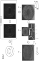
- Fig. 1 shows a method of manufacturing the porous structure 10.
- the data representing the external shape of the porous structure 10 is initially created as a three-dimensional (3D) model, as illustrated in Fig. 1 (upper left corner).
- the porous structure 10 is depicted as a cylindrical porous structure with a predetermined thickness, designed to be attached to a cylinder (not shown) that extends in one direction.
- the shape of the porous structure 10 can be any shape. Note that a 3D printer is used in this embodiment, as will be described later, and thus, any shape can be typically adaptable as the shape of the porous structure 10, and a desired shape can also be easily created.
- MEGG3D is software for creating mesh structures (obtained by combining column elements) used in computational fluid dynamics (CFD), which the Japan Aerospace Exploration Agency (JAXA: registered trademark) has developed.
- the software for creating mesh structures in computational fluid dynamics (CFD) is not limited to MEGG3D; other software may be used.
- MEGG3D is capable of creating data of the porous structure 10 suitable for aerodynamic noise reduction based on flow information predicted by CFD simulations under various conditions (e.g., flight speed and altitude of an aircraft 20) at the location where the porous structure 10 is to be attached.
- tetrahedral elements 2 in the preliminary data vary while considering fluid flow in CFD and aerodynamic noise reduction.
- Each tetrahedral element 2 is non-uniform and irregular and does not have to be a regular tetrahedron.
- each tetrahedral element 2 in the preliminary data is divided into multiple (four) hexahedral elements 3 (see also Fig. 2 to be described later) to generate the data of the porous structure 10 with hexahedral element 3 (upper right side of Fig. 1 ).
- each hexahedral element 3 is non-uniform and irregular and does not have to be a regular hexahedron.
- Fig. 2 shows a tetrahedral element 2 divided into hexahedral elements 3 using MEGG3D.
- tetrahedral element 2 when the tetrahedral element 2 is divided into multiple (four) hexahedral elements 3 using MEGG3D, for each of the four triangles of the tetrahedral element 2, three first points on the three column elements 1 of the triangle (see the black circles) are first determined. Note that the first point divides each of the three column elements 1 into two column elements 1.
- the first point is near the midpoint of each column element 1 of the triangle, but it is not considered located at the exact midpoint because of the variation in shapes of elements described above.
- Triangles next to each other have a common column element 1, and one first point is determined for that column element 1. Therefore, for one tetrahedral element 2, the total number of first points is six (4 ⁇ 3/2).
- a single second point inside the triangle is determined.
- the second point is near the center of the triangle, but it is not considered to be located at the exact center because of the variation in elements' shapes described above.
- the total number of second points in the tetrahedral element 2 is four.
- a third point inside the tetrahedral element 2 is determined.
- the third point is near the center of the tetrahedron but is not considered located at the exact center because of the variation in elements' shapes described above.
- four column elements 1, connecting the four second points (see white circles) and the single third point, are added further.
- the single tetrahedral element 2 is divided into the four hexahedral elements 3 in MEGG3D.
- column element 1 is used herein to mean a column component constituting each side of the hexahedral element 3 unless otherwise explicitly stated.
- CAD computer-aided design
- CAA computer graphics aided three-dimensional interactive application
- the coordinates of the start point 1a and the end point 1b of each column element 1 in the CAD software can also be output to spreadsheet software (e.g., Excel (registered trademark)) and then linked.
- spreadsheet software e.g., Excel (registered trademark)
- updating the coordinates of the start point 1a and the end point 1b on the spreadsheet software also makes it possible to partially change the shape of the hexahedral element 3 and partially adjust the porosity manually for optimization.
- unification processing summing processing of the column elements 1 is executed in the CAD software (lower center of Fig. 1 ).
- the unification processing is executed for unifying the column elements 1.
- This unification processing eliminates an overlapping portion where the column elements 1 overlap, and a valley line (indicated by the black arrow) is generated at the intersection of the column elements 1 on the CAD software. Note that the unification processing is performed for each column element 1, which can be automatically processed by a macro.
- This unification processing can reduce the volume of STL data that is ultimately output to the 3D printer and also prevents errors caused by the 3D printer.
- a base 11 is positioned below the porous structure 10, along with columns 12 that connect the base 11 to the porous structure 10. It is important to note that mounting seats (not shown) or similar features for attaching the porous structure 10 to an object can also be included.
- the porous structure 10 data generated in the CAD software (including the porous structure 10 made of hexahedral elements 3 and the other components 11 and 12) is exported to the 3D printer as an STL file.
- the 3D printer then three-dimensionally forms the porous structure 10 (modeled object including the porous structure 10) based on the input data.
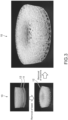
- Fig. 3 shows the porous structure 10 generated by the 3D printer. As shown in Fig. 3 , the base 11 and columns 12 on the lower side of the porous structure 10 are first removed from the modeled object, including the porous structure 10 generated by the 3D printer, so the porous structure 10 is manufactured.
- Fig. 3 shows an example of the porous structure 10 made of resin.
- Fig. 4 is a perspective view showing an example in which the porous structure 10 is made of metal (SUS) (column elements 1 have a diameter of 0.2 mm).
- Fig. 5 is a top view showing an example in which the porous structure 10 is made of metal (SUS) (column elements have a diameter of 0.2 mm).
- the porous structure 10, according to the present technology is manufactured using the manufacturing method described above. Therefore, the porous structure 10, according to the present technology, is created by the 3D printer based on the data of a porous structure 10 suitable for aerodynamic noise reduction under specific conditions (e.g., flight speed and altitude of an aircraft 20), the data being created based on software for creating mesh structures used in computational fluid dynamics.
- the porous structure 10 comprises a mesh with hexahedral elements 3.
- each hexahedral element 3 is formed by dividing a tetrahedral element 2 into multiple (four) hexahedral elements 3.
- each of the six column elements of the tetrahedral element 2 is divided into two column elements 1 by the first point.
- the porous structure 10 can be made of various materials, such as resin and metal.
- the porous structure 10 may be made entirely of the same material or partially of different materials.
- Fig. 6 shows an example of the porous structure 10.
- the porosity was set to 83%.
- the porosity is set to 80% or higher. Note that when the number of polyhedral elements, each with n faces, is consistent in a given volume, the porosity increases as the value of n rises.
- the porous structure 10 may be filled with polyhedral elements with larger n, such as pentahedral, heptahedral, and octahedral elements, which is generally difficult to obtain.
- hexahedral elements 3 are employed in this embodiment. With hexahedral elements 3, the porosity can be set to a relatively high value. In addition, hexahedral elements 3 can be formed by dividing the tetrahedral element 2 into multiple (four) pieces, which can thus be easily created.
- Fig. 7 shows a distribution of the lengths of the column elements 1 of the hexahedral element 3.
- the horizontal axis represents the range of the column element 1 lengths
- the vertical axis represents the number of column elements 1 with lengths included within that range.
- the total number of column elements 1 in the porous structure 10 was approximately 6000.
- the mean value of the column element lengths 1 was 1.97 mm
- the median value was 1.72 mm.
- Fig. 7 shows that the column element 1 lengths are distributed around the target length (2 mm).
- Fig. 8 shows a porous structure 10 attached to an aircraft 20.
- the porous structure 10 e.g., made of metal
- the airflow is first analyzed based on conditions such as the flight speed and flight altitude of the aircraft 20 when the landing gear door 21 is open (during takeoff and landing).
- hexahedral elements 3 with varying shapes suitable for aerodynamic noise reduction under those conditions is then generated by MEGG3D, and the porous structure 10 is manufactured accordingly.
- Attaching the porous structure 10 to the inner surface of the landing gear door 21 of the aircraft 20 makes it possible to reduce aerodynamic noise caused by the landing gear 22 or landing gear door 21.
- the aircraft 20 is used as an object to which the porous structure 10 is attached, but the object is not limited to aircraft 20.
- the object may be an automobile, railroad vehicle, or the like.
- an object to which the porous structure 10 is attached may be any object with a problem of aerodynamic noise.
- the porous structure 10 can be attached to any location.
- the first comparative example assumes that a ready-made metal product, Celmet (registered trademark: manufactured by Sumitomo Electric Toyama Co., Ltd.), is used as the porous structure 10 (see Example 4 in paragraph [0055] of Patent Literature 1 mentioned above).
- Celmet registered trademark: manufactured by Sumitomo Electric Toyama Co., Ltd.
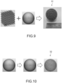
- Fig. 9 shows the second comparative example.
- a lattice structure by a 3D printer proposed by JAMPT Corporation (registered trademark) is assumed to be used as the porous structure 10.
- a lattice shape that serves as a basic unit is first created.
- This lattice shape is then arranged in 3D to generate data representing a modeled object as a simple cuboid (shown on the left side of Fig. 9 ).
- the next step is to create the shape data for an arbitrary modeling object, which will indicate the shape of the final modeling object (e.g., sphere: center of Fig. 9 ).
- this modeled object 31 is used as the porous structure 10, curved surface portions are missing, resulting in a sharp skeletal structure that protrudes from the surface and makes it difficult to handle.
- Fig. 10 shows the third comparative example. Similar to the second comparative example, a lattice structure by a 3D printer, proposed by JAMPT Corporation (registered trademark), is assumed to be used as the porous structure 10 .
- the edges of triangles in STL data are used to form a modeled object 32.
- This modeled object 32 consists solely of a surface structure, which presents significant limitations: no internal structure can be formed. Another problem is that only a triangular lattice can be generated on the surface.
- the fourth comparative example assumes that a lattice structure created with design software for a 3D printer is used as a porous structure.
- the design software automatically generates the lattice structure by adjusting parameters, such as density and thickness, based on a predetermined pattern function related to the target modeled object.
- a porous structure 10 is generated by the 3D printer based on data that defines a suitable design for reducing aerodynamic noise under specific conditions.
- the data is derived from software that generates mesh structures used in computational fluid dynamics.
- This embodiment allows for the straightforward creation of a porous structure 10 that effectively reduces aerodynamic noise.
- the sharp skeletal structure also does not protrude from the surface, making the porous structure 10 easy to handle.
- the porous structure 10 is created using a 3D printer, allowing for easy customization according to the shape of the object that it will be attached to. This feature facilitates the attachment of the porous structure 10 to objects with complicated shapes. Furthermore, incorporating mounting seats into the 3D model of the porous structure 10 simplifies securing it to the object.
- the porosity can be partially adjusted.
- the aerodynamic noise reduction effect can be optimized.
- the porous structure 10 is created from a mesh with hexahedral elements 3. Using these hexahedral elements 3 makes achieving a high porosity that effectively reduces aerodynamic noise possible.
- the porous structure 10 in this embodiment is created by dividing tetrahedral elements 2 into multiple hexahedral elements 3. This division method allows for the easy formation of a porous structure 10 composed of these hexahedral elements 3.
- the porous structure 10 in this embodiment includes, for each of the four triangles of every tetrahedral element 2 includes three column elements 1 that connect three first points on the three column elements 1 of the triangle and a single second point inside the triangle (12 column elements 1 in total).
- the porous structure 10 also includes four column elements 1 that connect the four second points inside the four triangles of the tetrahedral element 2 and a single third point inside the tetrahedral element 2.
Landscapes
- Engineering & Computer Science (AREA)
- Physics & Mathematics (AREA)
- Chemical & Material Sciences (AREA)
- Manufacturing & Machinery (AREA)
- Materials Engineering (AREA)
- Theoretical Computer Science (AREA)
- Geometry (AREA)
- General Physics & Mathematics (AREA)
- Multimedia (AREA)
- Acoustics & Sound (AREA)
- Fluid Mechanics (AREA)
- Aviation & Aerospace Engineering (AREA)
- Computer Hardware Design (AREA)
- Evolutionary Computation (AREA)
- Mechanical Engineering (AREA)
- General Engineering & Computer Science (AREA)
- Combustion & Propulsion (AREA)
- Pure & Applied Mathematics (AREA)
- Mathematical Analysis (AREA)
- Automation & Control Theory (AREA)
- Mathematical Optimization (AREA)
- Computing Systems (AREA)
- Mathematical Physics (AREA)
- Algebra (AREA)
- Computational Mathematics (AREA)
- Optics & Photonics (AREA)
- Powder Metallurgy (AREA)
- Soundproofing, Sound Blocking, And Sound Damping (AREA)
Abstract
To provide a technology or the like capable of quickly creating a structure suitable for aerodynamic noise reduction, a porous structure according to the present technology is produced by a three-dimensional printer based on data of a porous structure suitable for aerodynamic noise reduction under specific conditions, the data being created based on software for creating mesh structures used in computational fluid dynamics.
Description
- The present technology relates to a technology of porous structures for aerodynamic noise reduction or the like.
- Conventionally, it has been known that structures for aerodynamic noise reduction are attached to the surfaces of objects and the like.
- For example,
Patent Literature 1 below discloses that aerodynamic noise can be reduced by attaching porous material to portions of railroad vehicles, automobiles, aircraft, and the like. - Patent Literature 1:
Japanese Patent Application Laid-open No. 2008-136332 - In such fields, there is a need for a technology or the like capable of quickly creating a structure suitable for aerodynamic noise reduction.
- Given the circumstances described above, the objective of the present technology is to provide a technology or the like capable of quickly creating a structure suitable for aerodynamic noise reduction. Solution to Problem
- According to the present technology, a porous structure is created by a three-dimensional printer based on data of a porous structure suitable for aerodynamic noise reduction under specific conditions. The data is created based on software for creating mesh structures in computational fluid dynamics.
- This technology makes it possible to easily create a porous structure suitable for aerodynamic noise reduction.
- The porous structure may be formed of a mesh with hexahedral elements.
- The hexahedral elements may be formed in the porous structure by dividing tetrahedral elements into multiple hexahedral elements.
- In the porous structure, when the tetrahedral elements are divided into multiple hexahedral elements, for each of the four triangles of every tetrahedral element, three column elements may be added; these three column elements connecting three first points on the three column elements of the triangle, and a single second point inside the triangle.
- In the porous structure, when the tetrahedral elements are divided into multiple hexahedral elements, four column elements may further be added for every tetrahedral element, the four column elements connecting the four second points inside the four triangles in the tetrahedral element and a single third point inside the tetrahedral element.
- The porous structure may be formed according to the shape of an object to which the porous structure is to be attached.
- The porous structure may include mounting seats for attaching the porous structure to an object.
- Preliminary data may be generated using the software in the porous structure, where tetrahedral elements are used for discretization. The preliminary data can then be processed to divide the tetrahedral elements into multiple hexahedral elements. As a result, data can be generated for the porous structure that uses hexahedral elements for discretization.
- In the porous structure, when tetrahedral elements are divided into multiple hexahedral elements in the software, for each of the four triangles of every tetrahedral element, three column elements may be added; these three column elements connect three first points on the three column elements of the triangle and a single second point inside the triangle.
- In the porous structure, when tetrahedral elements are divided into multiple hexahedral elements in the software, four column elements may further be added for every tetrahedral element; these four column elements connect the four second points inside the four triangles of the tetrahedral element and a single third point inside the tetrahedral element.
- In the porous structure, the software may be MEGG3D.
- The porous structure may be used in the aircraft.
- According to the present technology, a porous structure for aerodynamic noise reduction is composed of a mesh with hexahedral elements; these hexahedral elements are formed by dividing tetrahedral elements into multiple hexahedral elements.
- According to the present technology, manufacturing porous structures includes creating data of a porous structure suitable for aerodynamic noise reduction under an actual condition based on software for creating mesh structures used in computational fluid dynamics and creating porous structures by a three-dimensional printer based on the created data. Advantageous Effects of Invention
- As described above, according to the present technology, it is possible to provide a technology or the like capable of quickly creating porous structures suitable for aerodynamic noise reduction.
-
- [
Fig. 1] Fig. 1 shows a porous structure manufacturing method. - [
Fig. 2] Fig. 2 shows a tetrahedral element divided into hexahedral elements using MEGG3D. - [
Fig. 3] Fig. 3 shows a porous structure generated by a 3D printer. - [
Fig. 4] Fig. 4 is a perspective view showing an example in which the porous structure is made of metal. - [
Fig. 5] Fig. 5 is a top view showing an example in which the porous structure is made of metal. - [
Fig. 6] Fig. 6 shows an example of the porous structure. - [
Fig. 7] Fig. 7 shows a distribution of the lengths of the column elements of the hexahedral elements in the porous structure. - [
Fig. 8] Fig. 8 shows a porous structure attached to an aircraft. - [
Fig. 9] Fig. 9 shows the second comparative example. - [
Fig. 10] Fig. 10 shows the third comparative example. Mode(s) for Carrying Out the Invention - Hereinafter, an embodiment of the present technology is described with reference to the figures.
- First, a method of manufacturing a
porous structure 10 is described according to the first embodiment of the present technology.Fig. 1 shows a method of manufacturing theporous structure 10. - The data representing the external shape of the
porous structure 10 is initially created as a three-dimensional (3D) model, as illustrated inFig. 1 (upper left corner). In this example, theporous structure 10 is depicted as a cylindrical porous structure with a predetermined thickness, designed to be attached to a cylinder (not shown) that extends in one direction. - The shape of the
porous structure 10 can be any shape. Note that a 3D printer is used in this embodiment, as will be described later, and thus, any shape can be typically adaptable as the shape of theporous structure 10, and a desired shape can also be easily created. - Once the data of the 3D model (external form) of the
porous structure 10 is created, this data is then exported as a stereolithography (STL) file imported to MEGG3D. MEGG3D is software for creating mesh structures (obtained by combining column elements) used in computational fluid dynamics (CFD), which the Japan Aerospace Exploration Agency (JAXA: registered trademark) has developed. The software for creating mesh structures in computational fluid dynamics (CFD) is not limited to MEGG3D; other software may be used. - MEGG3D is capable of creating data of the
porous structure 10 suitable for aerodynamic noise reduction based on flow information predicted by CFD simulations under various conditions (e.g., flight speed and altitude of an aircraft 20) at the location where theporous structure 10 is to be attached. - In MEGG3D, first, preliminary data of the
porous structure 10 with tetrahedral elements 2 (see alsoFig. 2 to be described later) is generated (upper center ofFig. 1 ) according to the 3D model (external form) of theporous structure 10. - The shapes of
tetrahedral elements 2 in the preliminary data vary while considering fluid flow in CFD and aerodynamic noise reduction. Eachtetrahedral element 2 is non-uniform and irregular and does not have to be a regular tetrahedron. - Next, in MEGG3D, each
tetrahedral element 2 in the preliminary data is divided into multiple (four) hexahedral elements 3 (see alsoFig. 2 to be described later) to generate the data of theporous structure 10 with hexahedral element 3 (upper right side ofFig. 1 ). - Similar to the
tetrahedral elements 2, the shapes of thehexahedral elements 3 in this data vary while considering fluid flow in CFD and aerodynamic noise reduction. Eachhexahedral element 3 is non-uniform and irregular and does not have to be a regular hexahedron. -
Fig. 2 shows atetrahedral element 2 divided intohexahedral elements 3 using MEGG3D. - As shown in
Fig. 2 , when thetetrahedral element 2 is divided into multiple (four)hexahedral elements 3 using MEGG3D, for each of the four triangles of thetetrahedral element 2, three first points on the threecolumn elements 1 of the triangle (see the black circles) are first determined. Note that the first point divides each of the threecolumn elements 1 into twocolumn elements 1. - The first point is near the midpoint of each
column element 1 of the triangle, but it is not considered located at the exact midpoint because of the variation in shapes of elements described above. Triangles next to each other have acommon column element 1, and one first point is determined for thatcolumn element 1. Therefore, for onetetrahedral element 2, the total number of first points is six (4×3/2). - Next, for each of the four triangles of the
tetrahedral element 2, a single second point inside the triangle (see the white circle) is determined. The second point is near the center of the triangle, but it is not considered to be located at the exact center because of the variation in elements' shapes described above. The total number of second points in thetetrahedral element 2 is four. - Next, for each of the four triangles of the
tetrahedral element 2, threecolumn elements 1 connecting the three first points (see the black circles) and the single second point (see the white circle) are determined. The total number ofcolumn elements 1 added to thetetrahedral element 2 in this step is 12 (4×3). - Next, a third point inside the tetrahedral element 2 (see the double circle) is determined. The third point is near the center of the tetrahedron but is not considered located at the exact center because of the variation in elements' shapes described above. Next, four
column elements 1, connecting the four second points (see white circles) and the single third point, are added further. - In such a manner, the single
tetrahedral element 2 is divided into the fourhexahedral elements 3 in MEGG3D. - Note that the term of the
column element 1 is used herein to mean a column component constituting each side of thehexahedral element 3 unless otherwise explicitly stated. - The coordinates of a
start point 1a and anend point 1b of eachcolumn element 1 of thehexahedral elements 3 in theporous structure 10 created by MEGG3D are output as text information to computer-aided design (CAD) software (e.g., computer graphics aided three-dimensional interactive application (CATIA): registered trademark) (lower right corner ofFig. 1 ). - Note that the coordinates of the
start point 1a and theend point 1b of eachcolumn element 1 in the CAD software can also be output to spreadsheet software (e.g., Excel (registered trademark)) and then linked. In this case, updating the coordinates of thestart point 1a and theend point 1b on the spreadsheet software also makes it possible to partially change the shape of thehexahedral element 3 and partially adjust the porosity manually for optimization. - Next, unification processing (summing processing) of the
column elements 1 is executed in the CAD software (lower center ofFig. 1 ). In other words, since thecolumn elements 1 merely overlap each other at this point, the unification processing is executed for unifying thecolumn elements 1. This unification processing eliminates an overlapping portion where thecolumn elements 1 overlap, and a valley line (indicated by the black arrow) is generated at the intersection of thecolumn elements 1 on the CAD software. Note that the unification processing is performed for eachcolumn element 1, which can be automatically processed by a macro. - This unification processing can reduce the volume of STL data that is ultimately output to the 3D printer and also prevents errors caused by the 3D printer.
- Next, additional components, aside from the
porous structure 10, are incorporated using the CAD software (as shown in the lower left corner ofFig. 1 ). In this example, abase 11 is positioned below theporous structure 10, along withcolumns 12 that connect the base 11 to theporous structure 10. It is important to note that mounting seats (not shown) or similar features for attaching theporous structure 10 to an object can also be included. - Next, the
porous structure 10 data generated in the CAD software (including theporous structure 10 made ofhexahedral elements 3 and theother components 11 and 12) is exported to the 3D printer as an STL file. The 3D printer then three-dimensionally forms the porous structure 10 (modeled object including the porous structure 10) based on the input data. -
Fig. 3 shows theporous structure 10 generated by the 3D printer. As shown inFig. 3 , thebase 11 andcolumns 12 on the lower side of theporous structure 10 are first removed from the modeled object, including theporous structure 10 generated by the 3D printer, so theporous structure 10 is manufactured. - Note that
Fig. 3 shows an example of theporous structure 10 made of resin.Fig. 4 is a perspective view showing an example in which theporous structure 10 is made of metal (SUS) (column elements 1 have a diameter of 0.2 mm). In addition,Fig. 5 is a top view showing an example in which theporous structure 10 is made of metal (SUS) (column elements have a diameter of 0.2 mm). - Next, a configuration of the
porous structure 10 is described. - The
porous structure 10, according to the present technology, is manufactured using the manufacturing method described above. Therefore, theporous structure 10, according to the present technology, is created by the 3D printer based on the data of aporous structure 10 suitable for aerodynamic noise reduction under specific conditions (e.g., flight speed and altitude of an aircraft 20), the data being created based on software for creating mesh structures used in computational fluid dynamics. - Further, the
porous structure 10 comprises a mesh withhexahedral elements 3. In addition, eachhexahedral element 3 is formed by dividing atetrahedral element 2 into multiple (four)hexahedral elements 3. - When the
tetrahedral element 2 is divided into thehexahedral elements 3, the followingcolumn elements 1 are added to the sixcolumn elements 1 of thetetrahedral element 2. Note that each of the six column elements of thetetrahedral element 2 is divided into twocolumn elements 1 by the first point. - In other words, when the
tetrahedral element 2 is divided into thehexahedral elements 3, for each of the four triangles of thetetrahedral element 2, threecolumn elements 1 are added, which connect three first points on the threecolumn elements 1 of the triangle (see the black circles ofFig. 2 ) and a single second point inside the triangle (see the white circle ofFig. 2 ) (12column elements 1 in total). - In addition, when the
tetrahedral element 2 is divided into thehexahedral elements 3, fourcolumn elements 1 are further added, which connect the four second points inside the four triangles of the tetrahedral element 2 (see the white circles ofFig. 2 ) and a single third point inside the tetrahedral element 2 (see the double circle ofFig. 2 ). - The
porous structure 10 can be made of various materials, such as resin and metal. Theporous structure 10 may be made entirely of the same material or partially of different materials. -
Fig. 6 shows an example of theporous structure 10. - In this
porous structure 10, the porosity was set to 83%. Here, it is known that a higher porosity is more effective in reducing aerodynamic noise. Typically, the porosity is set to 80% or higher. Note that when the number of polyhedral elements, each with n faces, is consistent in a given volume, the porosity increases as the value of n rises. - A
tetrahedral element 2 has n = 4, and it is difficult to increase the porosity (there is a difference in porosity of 10% to 20% when filling a given volume with the same number oftetrahedral elements 2 or hexahedral elements 3). In addition, theporous structure 10 may be filled with polyhedral elements with larger n, such as pentahedral, heptahedral, and octahedral elements, which is generally difficult to obtain. - In this regard,
hexahedral elements 3 are employed in this embodiment. Withhexahedral elements 3, the porosity can be set to a relatively high value. In addition,hexahedral elements 3 can be formed by dividing thetetrahedral element 2 into multiple (four) pieces, which can thus be easily created. - In addition, in the example shown in
Fig. 6 , resin (Vitra-413: model number of resin manufactured by DWS (registered trademark)) was used as the material of theporous structure 10. Additionally, the outer diameter of theporous structure 10 was 45 mm, the inner diameter was 25 mm, and the thickness was 10 mm. Further, the diameter ofcolumn elements 1 of thehexahedral elements 3 was 0.5 mm, and the target length of thecolumn elements 1 was 2 mm. Note that thecolumns 12 formed on thebase 11 were set to have a diameter of 0.4 mm. - It is understood that aerodynamic noise reduction is more effective when the number of polyhedral elements ranges from approximately 11 to 16 in 25 mm (1 inch). In this example, the target length of
column elements 1 was set to 2 mm, corresponding to about 25.4 mm divided by 13 polyhedral elements. As described above, the shape of thehexahedral elements 3 in theporous structure 10 vary. Therefore, there is a distribution in theactual column element 1 lengths. -
Fig. 7 shows a distribution of the lengths of thecolumn elements 1 of thehexahedral element 3. InFig. 7 , the horizontal axis represents the range of thecolumn element 1 lengths, and the vertical axis represents the number ofcolumn elements 1 with lengths included within that range. In this example, the total number ofcolumn elements 1 in theporous structure 10 was approximately 6000. In addition, the mean value of thecolumn element lengths 1 was 1.97 mm, and the median value was 1.72 mm. -
Fig. 7 shows that thecolumn element 1 lengths are distributed around the target length (2 mm). -
Fig. 8 shows aporous structure 10 attached to anaircraft 20. As shown inFig. 8 , the porous structure 10 (e.g., made of metal) is attached to the inner surface of alanding gear door 21 of theaircraft 20. When thisporous structure 10 is manufactured, the airflow is first analyzed based on conditions such as the flight speed and flight altitude of theaircraft 20 when thelanding gear door 21 is open (during takeoff and landing).hexahedral elements 3 with varying shapes suitable for aerodynamic noise reduction under those conditions is then generated by MEGG3D, and theporous structure 10 is manufactured accordingly. - Attaching the
porous structure 10 to the inner surface of thelanding gear door 21 of theaircraft 20 makes it possible to reduce aerodynamic noise caused by thelanding gear 22 orlanding gear door 21. - In this example, the
aircraft 20 is used as an object to which theporous structure 10 is attached, but the object is not limited toaircraft 20. For example, the object may be an automobile, railroad vehicle, or the like. Typically, an object to which theporous structure 10 is attached may be any object with a problem of aerodynamic noise. Additionally, theporous structure 10 can be attached to any location. - Next, the actions etc. in the
porous structure 10 according to this embodiment are described, including comparative examples. - The first comparative example assumes that a ready-made metal product, Celmet (registered trademark: manufactured by Sumitomo Electric Toyama Co., Ltd.), is used as the porous structure 10 (see Example 4 in paragraph [0055] of
Patent Literature 1 mentioned above). - Using the ready-made metal product Celmet as a
porous structure 10 presents some difficulties. Its sharp skeletal structure protrudes from the surface, making it difficult to handle. Additionally, adapting theporous structure 10 to fit the shape of the object that it will be attached to is problematic. Finally, securing the porous structure to the object poses further difficulties. -
Fig. 9 shows the second comparative example. In this example, a lattice structure by a 3D printer proposed by JAMPT Corporation (registered trademark) is assumed to be used as theporous structure 10. - In the second comparative example, as shown in
Fig. 9 , a lattice shape that serves as a basic unit is first created. This lattice shape is then arranged in 3D to generate data representing a modeled object as a simple cuboid (shown on the left side ofFig. 9 ). The next step is to create the shape data for an arbitrary modeling object, which will indicate the shape of the final modeling object (e.g., sphere: center ofFig. 9 ). - Next, superimposing those two pieces of data is performed in conversion software. The data is then exported to a 3D printer, and a modeled
object 31 is fabricated by the 3D printer (right side ofFig. 9 ). - If this modeled
object 31 is used as theporous structure 10, curved surface portions are missing, resulting in a sharp skeletal structure that protrudes from the surface and makes it difficult to handle. -
Fig. 10 shows the third comparative example. Similar to the second comparative example, a lattice structure by a 3D printer, proposed by JAMPT Corporation (registered trademark), is assumed to be used as theporous structure 10. - In the third comparative example, the edges of triangles in STL data are used to form a modeled
object 32. This modeledobject 32 consists solely of a surface structure, which presents significant limitations: no internal structure can be formed. Another problem is that only a triangular lattice can be generated on the surface. - The fourth comparative example assumes that a lattice structure created with design software for a 3D printer is used as a porous structure. In this example, the design software automatically generates the lattice structure by adjusting parameters, such as density and thickness, based on a predetermined pattern function related to the target modeled object.
- In the fourth comparative example, it is possible to create a lattice structure that conforms to a target shape, including curves and similar features. However, a problem arises in producing a structure that reduces aerodynamic noise reduction.
- According to this embodiment, a
porous structure 10 is generated by the 3D printer based on data that defines a suitable design for reducing aerodynamic noise under specific conditions. The data is derived from software that generates mesh structures used in computational fluid dynamics. - This embodiment allows for the straightforward creation of a
porous structure 10 that effectively reduces aerodynamic noise. The sharp skeletal structure also does not protrude from the surface, making theporous structure 10 easy to handle. - In this embodiment, the
porous structure 10 is created using a 3D printer, allowing for easy customization according to the shape of the object that it will be attached to. This feature facilitates the attachment of theporous structure 10 to objects with complicated shapes. Furthermore, incorporating mounting seats into the 3D model of theporous structure 10 simplifies securing it to the object. - Additionally, in the
porous structure 10, the porosity can be partially adjusted. In this case, the aerodynamic noise reduction effect can be optimized. - In this embodiment, the
porous structure 10 is created from a mesh withhexahedral elements 3. Using thesehexahedral elements 3 makes achieving a high porosity that effectively reduces aerodynamic noise possible. - The
porous structure 10 in this embodiment is created by dividingtetrahedral elements 2 into multiplehexahedral elements 3. This division method allows for the easy formation of aporous structure 10 composed of thesehexahedral elements 3. - The
porous structure 10 in this embodiment includes, for each of the four triangles of everytetrahedral element 2 includes threecolumn elements 1 that connect three first points on the threecolumn elements 1 of the triangle and a single second point inside the triangle (12column elements 1 in total). Theporous structure 10 also includes fourcolumn elements 1 that connect the four second points inside the four triangles of thetetrahedral element 2 and a single third point inside thetetrahedral element 2. - This approach makes it possible to obtain
porous structure 10 withhexahedral elements 3 converted from the structure withtetrahedral elements 2. -
- 1
- column element
- 2
- tetrahedral element
- 3
- hexahedral element
- 10
- porous structure
Claims (14)
- A porous structure created by a three-dimensional printer based on data suitable for aerodynamic noise reduction under specific conditions, the data created based on software for creating mesh structures used in computational fluid dynamics.
- The porous structure, according to claim 1, wherein
the porous structure is formed of a mesh with hexahedral elements. - The porous structure, according to claim 2, wherein
the hexahedral elements are formed by dividing tetrahedral elements into multiple hexahedral elements. - The porous structure, according to claim 3, wherein
when the tetrahedral elements are divided into multiple hexahedral elements, for each of the four triangles of every tetrahedral element, three column elements are added, the three column elements connecting three first points on the three column elements of the triangle and a single second point inside the triangle. - The porous structure, according to claim 4, wherein
when the tetrahedral elements are divided into multiple hexahedral elements, four column elements are further added for every tetrahedral element, the four column elements connecting the four second points inside the four triangles of the tetrahedral element and a single third point inside the tetrahedral element. - The porous structure, according to claim 1, wherein
the porous structure is formed according to the shape of an object to which the porous structure is to be attached. - The porous structure, according to claim 1, wherein
the porous structure includes mounting seats for attaching the porous structure to an object. - The porous structure, according to claim 3, wherein
in the software, preliminary data of the porous structure in which tetrahedral elements are used for discretization is generated, the tetrahedral elements in the preliminary data are divided into multiple hexahedral elements, and data of the porous structure in which the hexahedral elements are used for discretization is generated. - The porous structure, according to claim 8, wherein
in the software, when the tetrahedral elements are divided into multiple hexahedral elements, for each of four triangles of every tetrahedral element, three column elements are added, the three column elements connecting three first points on the three column elements of the triangle and a single second point inside the triangle. - The porous structure, according to claim 9, wherein
in the software, when the tetrahedral elements are divided into multiple hexahedral elements, four column elements are further added for every tetrahedral element, the four column elements connecting the four second points inside the four triangles in the tetrahedral element and a single third point inside the tetrahedral element. - The porous structure, according to claim 1, wherein
the software is MEGG3D. - The porous structure, according to claim 1, wherein
the porous structure is used in the aircraft. - A porous structure for aerodynamic noise reduction; the porous structure is formed of a mesh with hexahedral elements, and the hexahedral elements are formed by dividing tetrahedral elements into multiple hexahedral elements.
- A method of manufacturing a porous structure comprising:creating data of a porous structure suitable for aerodynamic noise reduction under specific conditions based on software for creating mesh structures used with computational fluid dynamics andcreating a porous structure by a three-dimensional printer based on the created data.
Applications Claiming Priority (2)
| Application Number | Priority Date | Filing Date | Title |
|---|---|---|---|
| JP2022101017A JP2024002053A (en) | 2022-06-23 | 2022-06-23 | Porous structure, porous structure for aerodynamic noise reduction, method for manufacturing porous structure |
| PCT/JP2023/019847 WO2023248721A1 (en) | 2022-06-23 | 2023-05-29 | Porous structural body, porous structural body for reducing aerodynamic noise, porous structural body manufacturing method |
Publications (1)
| Publication Number | Publication Date |
|---|---|
| EP4545663A1 true EP4545663A1 (en) | 2025-04-30 |
Family
ID=89379737
Family Applications (1)
| Application Number | Title | Priority Date | Filing Date |
|---|---|---|---|
| EP23826909.6A Pending EP4545663A1 (en) | 2022-06-23 | 2023-05-29 | Porous structural body, porous structural body for reducing aerodynamic noise, porous structural body manufacturing method |
Country Status (4)
| Country | Link |
|---|---|
| US (1) | US20250384865A1 (en) |
| EP (1) | EP4545663A1 (en) |
| JP (1) | JP2024002053A (en) |
| WO (1) | WO2023248721A1 (en) |
Families Citing this family (1)
| Publication number | Priority date | Publication date | Assignee | Title |
|---|---|---|---|---|
| CN118005019A (en) | 2022-11-08 | 2024-05-10 | 信越化学工业株式会社 | Polycrystalline silicon rod and method for manufacturing polycrystalline silicon rod |
Family Cites Families (2)
| Publication number | Priority date | Publication date | Assignee | Title |
|---|---|---|---|---|
| JP5083863B2 (en) | 2006-10-23 | 2012-11-28 | 公益財団法人鉄道総合技術研究所 | Aerodynamic sound reduction structure |
| JP2020172212A (en) * | 2019-04-12 | 2020-10-22 | 株式会社ブリヂストン | Porous structure and vehicular headrest |
-
2022
- 2022-06-23 JP JP2022101017A patent/JP2024002053A/en active Pending
-
2023
- 2023-05-29 WO PCT/JP2023/019847 patent/WO2023248721A1/en not_active Ceased
- 2023-05-29 EP EP23826909.6A patent/EP4545663A1/en active Pending
- 2023-05-29 US US18/878,420 patent/US20250384865A1/en active Pending
Also Published As
| Publication number | Publication date |
|---|---|
| JP2024002053A (en) | 2024-01-11 |
| US20250384865A1 (en) | 2025-12-18 |
| WO2023248721A1 (en) | 2023-12-28 |
Similar Documents
| Publication | Publication Date | Title |
|---|---|---|
| Ito et al. | Surface triangulation for polygonal models based on CAD data | |
| US12111630B2 (en) | Method and system to generate three-dimensional meta-structure model of a workpiece | |
| US8831913B2 (en) | Method of design optimisation | |
| EP3251095B1 (en) | Generating slice data from a voxel representation | |
| US10796039B2 (en) | 3D finite element mesh of a 3D part that comprises a lattice structure | |
| US12530016B2 (en) | Watertight spline modeling for additive manufacturing | |
| EP4022486B1 (en) | Systems and method for processing topology optimized geometries | |
| US10706623B1 (en) | Systems and methods for preparing a virtual three-dimensional (3D) object for 3D printing | |
| US20250384865A1 (en) | Porous structural body, porous structural body for aerodynamic noise reduction, and method of manufacturing a porous structural body | |
| Azman et al. | Creation of lattice structures with skeleton model for additive manufacturing | |
| WO2023272523A1 (en) | Model reconstruction method, apparatus and system | |
| Vandenbrande et al. | The search for the perfect body: Shape control for multidisciplinary design optimization | |
| Azamatov et al. | Comprehensive aircraft configuration design tool for integrated product and process development | |
| CN106228617A (en) | Heterogeneous body NURBS body parameterized model Slicing Algorithm for rapid shaping | |
| DE102021200999A1 (en) | Modeling and manufacturing of an object based on a topology-optimized raw part | |
| US20080100619A1 (en) | Mesh generation method and computer-readable article for executing the method | |
| Gomez et al. | Free-Form Deformation of Parametric CAD Geometry via B-Spline Transformations | |
| Cerulli et al. | Parametric modeling of aircraft families for load calculation support | |
| Szabó | Application of topological methods in the development of vehicle components | |
| Inui et al. | Simple offset algorithm for generating workpiece solid model for milling simulation | |
| Jones | An open framework for unstructured grid generation | |
| Tolok et al. | Voxel modeling of the control of prototype manufacturing with additive technologies | |
| CN116868197A (en) | Transition structure generation for internal lattice structures of computer-aided design (CAD) objects | |
| Ito et al. | Surface triangulation for non-trimmed surface models | |
| EDWARDS | Definition and verification of a complex aircraft for aerodynamic calculations |
Legal Events
| Date | Code | Title | Description |
|---|---|---|---|
| STAA | Information on the status of an ep patent application or granted ep patent |
Free format text: STATUS: THE INTERNATIONAL PUBLICATION HAS BEEN MADE |
|
| PUAI | Public reference made under article 153(3) epc to a published international application that has entered the european phase |
Free format text: ORIGINAL CODE: 0009012 |
|
| STAA | Information on the status of an ep patent application or granted ep patent |
Free format text: STATUS: REQUEST FOR EXAMINATION WAS MADE |
|
| 17P | Request for examination filed |
Effective date: 20250123 |
|
| AK | Designated contracting states |
Kind code of ref document: A1 Designated state(s): AL AT BE BG CH CY CZ DE DK EE ES FI FR GB GR HR HU IE IS IT LI LT LU LV MC ME MK MT NL NO PL PT RO RS SE SI SK SM TR |
|
| DAV | Request for validation of the european patent (deleted) | ||
| DAX | Request for extension of the european patent (deleted) |