EP4545485A1 - Positive electrode active material, and preparation method therefor and use thereof - Google Patents
Positive electrode active material, and preparation method therefor and use thereof Download PDFInfo
- Publication number
- EP4545485A1 EP4545485A1 EP24772199.6A EP24772199A EP4545485A1 EP 4545485 A1 EP4545485 A1 EP 4545485A1 EP 24772199 A EP24772199 A EP 24772199A EP 4545485 A1 EP4545485 A1 EP 4545485A1
- Authority
- EP
- European Patent Office
- Prior art keywords
- active material
- cathode active
- phase
- cathode
- crystal domain
- Prior art date
- Legal status (The legal status is an assumption and is not a legal conclusion. Google has not performed a legal analysis and makes no representation as to the accuracy of the status listed.)
- Pending
Links
Images




Classifications
-
- H—ELECTRICITY
- H01—ELECTRIC ELEMENTS
- H01M—PROCESSES OR MEANS, e.g. BATTERIES, FOR THE DIRECT CONVERSION OF CHEMICAL ENERGY INTO ELECTRICAL ENERGY
- H01M10/00—Secondary cells; Manufacture thereof
- H01M10/05—Accumulators with non-aqueous electrolyte
- H01M10/054—Accumulators with insertion or intercalation of metals other than lithium, e.g. with magnesium or aluminium
-
- C—CHEMISTRY; METALLURGY
- C01—INORGANIC CHEMISTRY
- C01G—COMPOUNDS CONTAINING METALS NOT COVERED BY SUBCLASSES C01D OR C01F
- C01G53/00—Compounds of nickel
- C01G53/40—Complex oxides containing nickel and at least one other metal element
- C01G53/42—Complex oxides containing nickel and at least one other metal element containing alkali metals, e.g. LiNiO2
- C01G53/44—Complex oxides containing nickel and at least one other metal element containing alkali metals, e.g. LiNiO2 containing manganese
- C01G53/50—Complex oxides containing nickel and at least one other metal element containing alkali metals, e.g. LiNiO2 containing manganese of the type (MnO2)n-, e.g. Li(NixMn1-x)O2 or Li(MyNixMn1-x-y)O2
-
- C—CHEMISTRY; METALLURGY
- C01—INORGANIC CHEMISTRY
- C01G—COMPOUNDS CONTAINING METALS NOT COVERED BY SUBCLASSES C01D OR C01F
- C01G53/00—Compounds of nickel
- C01G53/40—Complex oxides containing nickel and at least one other metal element
- C01G53/42—Complex oxides containing nickel and at least one other metal element containing alkali metals, e.g. LiNiO2
- C01G53/44—Complex oxides containing nickel and at least one other metal element containing alkali metals, e.g. LiNiO2 containing manganese
- C01G53/50—Complex oxides containing nickel and at least one other metal element containing alkali metals, e.g. LiNiO2 containing manganese of the type (MnO2)n-, e.g. Li(NixMn1-x)O2 or Li(MyNixMn1-x-y)O2
- C01G53/51—Complex oxides containing nickel and at least one other metal element containing alkali metals, e.g. LiNiO2 containing manganese of the type (MnO2)n-, e.g. Li(NixMn1-x)O2 or Li(MyNixMn1-x-y)O2 containing sodium
-
- H—ELECTRICITY
- H01—ELECTRIC ELEMENTS
- H01M—PROCESSES OR MEANS, e.g. BATTERIES, FOR THE DIRECT CONVERSION OF CHEMICAL ENERGY INTO ELECTRICAL ENERGY
- H01M4/00—Electrodes
- H01M4/02—Electrodes composed of, or comprising, active material
- H01M4/04—Processes of manufacture in general
- H01M4/0471—Processes of manufacture in general involving thermal treatment, e.g. firing, sintering, backing particulate active material, thermal decomposition, pyrolysis
-
- H—ELECTRICITY
- H01—ELECTRIC ELEMENTS
- H01M—PROCESSES OR MEANS, e.g. BATTERIES, FOR THE DIRECT CONVERSION OF CHEMICAL ENERGY INTO ELECTRICAL ENERGY
- H01M4/00—Electrodes
- H01M4/02—Electrodes composed of, or comprising, active material
- H01M4/13—Electrodes for accumulators with non-aqueous electrolyte, e.g. for lithium-accumulators; Processes of manufacture thereof
- H01M4/131—Electrodes based on mixed oxides or hydroxides, or on mixtures of oxides or hydroxides, e.g. LiCoOx
-
- H—ELECTRICITY
- H01—ELECTRIC ELEMENTS
- H01M—PROCESSES OR MEANS, e.g. BATTERIES, FOR THE DIRECT CONVERSION OF CHEMICAL ENERGY INTO ELECTRICAL ENERGY
- H01M4/00—Electrodes
- H01M4/02—Electrodes composed of, or comprising, active material
- H01M4/36—Selection of substances as active materials, active masses, active liquids
- H01M4/48—Selection of substances as active materials, active masses, active liquids of inorganic oxides or hydroxides
- H01M4/50—Selection of substances as active materials, active masses, active liquids of inorganic oxides or hydroxides of manganese
- H01M4/505—Selection of substances as active materials, active masses, active liquids of inorganic oxides or hydroxides of manganese of mixed oxides or hydroxides containing manganese for inserting or intercalating light metals, e.g. LiMn2O4 or LiMn2OxFy
-
- H—ELECTRICITY
- H01—ELECTRIC ELEMENTS
- H01M—PROCESSES OR MEANS, e.g. BATTERIES, FOR THE DIRECT CONVERSION OF CHEMICAL ENERGY INTO ELECTRICAL ENERGY
- H01M4/00—Electrodes
- H01M4/02—Electrodes composed of, or comprising, active material
- H01M4/36—Selection of substances as active materials, active masses, active liquids
- H01M4/48—Selection of substances as active materials, active masses, active liquids of inorganic oxides or hydroxides
- H01M4/52—Selection of substances as active materials, active masses, active liquids of inorganic oxides or hydroxides of nickel, cobalt or iron
- H01M4/525—Selection of substances as active materials, active masses, active liquids of inorganic oxides or hydroxides of nickel, cobalt or iron of mixed oxides or hydroxides containing iron, cobalt or nickel for inserting or intercalating light metals, e.g. LiNiO2, LiCoO2 or LiCoOxFy
-
- H—ELECTRICITY
- H01—ELECTRIC ELEMENTS
- H01M—PROCESSES OR MEANS, e.g. BATTERIES, FOR THE DIRECT CONVERSION OF CHEMICAL ENERGY INTO ELECTRICAL ENERGY
- H01M4/00—Electrodes
- H01M4/02—Electrodes composed of, or comprising, active material
- H01M4/62—Selection of inactive substances as ingredients for active masses, e.g. binders, fillers
-
- C—CHEMISTRY; METALLURGY
- C01—INORGANIC CHEMISTRY
- C01P—INDEXING SCHEME RELATING TO STRUCTURAL AND PHYSICAL ASPECTS OF SOLID INORGANIC COMPOUNDS
- C01P2002/00—Crystal-structural characteristics
- C01P2002/50—Solid solutions
- C01P2002/52—Solid solutions containing elements as dopants
-
- C—CHEMISTRY; METALLURGY
- C01—INORGANIC CHEMISTRY
- C01P—INDEXING SCHEME RELATING TO STRUCTURAL AND PHYSICAL ASPECTS OF SOLID INORGANIC COMPOUNDS
- C01P2002/00—Crystal-structural characteristics
- C01P2002/70—Crystal-structural characteristics defined by measured X-ray, neutron or electron diffraction data
- C01P2002/72—Crystal-structural characteristics defined by measured X-ray, neutron or electron diffraction data by d-values or two theta-values, e.g. as X-ray diagram
-
- C—CHEMISTRY; METALLURGY
- C01—INORGANIC CHEMISTRY
- C01P—INDEXING SCHEME RELATING TO STRUCTURAL AND PHYSICAL ASPECTS OF SOLID INORGANIC COMPOUNDS
- C01P2002/00—Crystal-structural characteristics
- C01P2002/70—Crystal-structural characteristics defined by measured X-ray, neutron or electron diffraction data
- C01P2002/76—Crystal-structural characteristics defined by measured X-ray, neutron or electron diffraction data by a space-group or by other symmetry indications
-
- C—CHEMISTRY; METALLURGY
- C01—INORGANIC CHEMISTRY
- C01P—INDEXING SCHEME RELATING TO STRUCTURAL AND PHYSICAL ASPECTS OF SOLID INORGANIC COMPOUNDS
- C01P2004/00—Particle morphology
- C01P2004/01—Particle morphology depicted by an image
- C01P2004/03—Particle morphology depicted by an image obtained by SEM
-
- C—CHEMISTRY; METALLURGY
- C01—INORGANIC CHEMISTRY
- C01P—INDEXING SCHEME RELATING TO STRUCTURAL AND PHYSICAL ASPECTS OF SOLID INORGANIC COMPOUNDS
- C01P2004/00—Particle morphology
- C01P2004/50—Agglomerated particles
-
- C—CHEMISTRY; METALLURGY
- C01—INORGANIC CHEMISTRY
- C01P—INDEXING SCHEME RELATING TO STRUCTURAL AND PHYSICAL ASPECTS OF SOLID INORGANIC COMPOUNDS
- C01P2004/00—Particle morphology
- C01P2004/60—Particles characterised by their size
- C01P2004/61—Micrometer sized, i.e. from 1-100 micrometer
-
- C—CHEMISTRY; METALLURGY
- C01—INORGANIC CHEMISTRY
- C01P—INDEXING SCHEME RELATING TO STRUCTURAL AND PHYSICAL ASPECTS OF SOLID INORGANIC COMPOUNDS
- C01P2006/00—Physical properties of inorganic compounds
- C01P2006/11—Powder tap density
-
- C—CHEMISTRY; METALLURGY
- C01—INORGANIC CHEMISTRY
- C01P—INDEXING SCHEME RELATING TO STRUCTURAL AND PHYSICAL ASPECTS OF SOLID INORGANIC COMPOUNDS
- C01P2006/00—Physical properties of inorganic compounds
- C01P2006/12—Surface area
-
- C—CHEMISTRY; METALLURGY
- C01—INORGANIC CHEMISTRY
- C01P—INDEXING SCHEME RELATING TO STRUCTURAL AND PHYSICAL ASPECTS OF SOLID INORGANIC COMPOUNDS
- C01P2006/00—Physical properties of inorganic compounds
- C01P2006/40—Electric properties
-
- C—CHEMISTRY; METALLURGY
- C01—INORGANIC CHEMISTRY
- C01P—INDEXING SCHEME RELATING TO STRUCTURAL AND PHYSICAL ASPECTS OF SOLID INORGANIC COMPOUNDS
- C01P2006/00—Physical properties of inorganic compounds
- C01P2006/80—Compositional purity
-
- C—CHEMISTRY; METALLURGY
- C01—INORGANIC CHEMISTRY
- C01P—INDEXING SCHEME RELATING TO STRUCTURAL AND PHYSICAL ASPECTS OF SOLID INORGANIC COMPOUNDS
- C01P2006/00—Physical properties of inorganic compounds
- C01P2006/80—Compositional purity
- C01P2006/82—Compositional purity water content
-
- H—ELECTRICITY
- H01—ELECTRIC ELEMENTS
- H01M—PROCESSES OR MEANS, e.g. BATTERIES, FOR THE DIRECT CONVERSION OF CHEMICAL ENERGY INTO ELECTRICAL ENERGY
- H01M4/00—Electrodes
- H01M4/02—Electrodes composed of, or comprising, active material
- H01M2004/021—Physical characteristics, e.g. porosity, surface area
-
- H—ELECTRICITY
- H01—ELECTRIC ELEMENTS
- H01M—PROCESSES OR MEANS, e.g. BATTERIES, FOR THE DIRECT CONVERSION OF CHEMICAL ENERGY INTO ELECTRICAL ENERGY
- H01M4/00—Electrodes
- H01M4/02—Electrodes composed of, or comprising, active material
- H01M2004/026—Electrodes composed of, or comprising, active material characterised by the polarity
- H01M2004/028—Positive electrodes
-
- Y—GENERAL TAGGING OF NEW TECHNOLOGICAL DEVELOPMENTS; GENERAL TAGGING OF CROSS-SECTIONAL TECHNOLOGIES SPANNING OVER SEVERAL SECTIONS OF THE IPC; TECHNICAL SUBJECTS COVERED BY FORMER USPC CROSS-REFERENCE ART COLLECTIONS [XRACs] AND DIGESTS
- Y02—TECHNOLOGIES OR APPLICATIONS FOR MITIGATION OR ADAPTATION AGAINST CLIMATE CHANGE
- Y02E—REDUCTION OF GREENHOUSE GAS [GHG] EMISSIONS, RELATED TO ENERGY GENERATION, TRANSMISSION OR DISTRIBUTION
- Y02E60/00—Enabling technologies; Technologies with a potential or indirect contribution to GHG emissions mitigation
- Y02E60/10—Energy storage using batteries
Definitions
- This application relates to the technical field of sodium ion batteries, and particularly relates to a cathode active material and a preparation method therefor and an application thereof.
- an electrochemical energy storage system (EES) is considered an effective method to balance cycle performance of renewable energy sources.
- Secondary batteries in electrochemical energy storage have a huge potential.
- Lithium ion batteries dominate the energy storage market as a result of high theoretical specific capacity and specific energy density.
- a sodium-based layered oxide cathode material is one of the most critical materials for sodium ion batteries. Similar to lithium cobalt oxides and ternary structures of lithium ion batteries, the layered oxide structure has a good ion channel, with probably a certain dead end in cycle performance, but the average maturity is relatively high.
- a transition metal oxide Na X MeO 2 is an embedded or intercalated compound. It has a higher specific discharge capacity theoretically but poor cycle performance. By introducing active or inert elements for doping or substituting, the defect can be improved.
- the type of the layered oxide mainly includes O2 type, O3 type, P2 type, and P3 type, where O or P represents the position of Na + in an octahedron or a prism, and figures represent repeatedly arranged units of different oxide layers.
- O3 type and P2 type are relatively stable phase structures. There is much work conducted for these two types. Compared with its electrochemical performance, although there are some differences, in a word, a transition metal oxide system is still a route with relatively high maturity at present.
- the types in the layered oxide materials of existing sodium ion batteries are significant in defect (the O3 type material is high in capacity, low in first effect, and poor in cycle performance, and often has problems of massive aerogenesis, metal dissolution, and structure evolution in a total battery application process; the P2 type material is relatively low in initial charge capacity, but is good in cycle performance and rate performance; and the P3 type material is low in capacity, poor in cycle, high in working voltage, and the like), so that the comprehensive performance is poor.
- the types are hardly combined together organically. Core-shell coating and direct blending methods in conventional methods often introduce new electrochemical inert substances or have new two-phase interfacial problem, which results in poor electrochemical performance of the material, thereby bringing resistance to industrial application of the sodium ion batteries.
- the cathode active material is the layered oxide with the double crystal domain structure, and the cathode active material meeting the crystal domain heterogeneity degree has a higher capacity of separating sodium ions and has a higher specific capacity. Moreover, the double crystal domain structure can relieve irreversible transition and interlayer slipping of the structure under a high voltage as massive sodium ions are separated, so that the stability of the material is better enhanced. The above integrally improves the electrochemical performance of the cathode active material in the technical solution of this application, which facilitates wide application.
- the doping element M is selected from at least one of Li, K, Rb, Be, Mg, Ca, Cu, Sr, and Zn.
- the preparation method for the cathode active material is simple, and the prepared cathode active material is the layered oxide with the double crystal domain structure, and the cathode active material meeting the crystal domain heterogeneity degree has a higher capacity of separating sodium ions and has a higher specific capacity. Moreover, the double crystal domain structure can relieve irreversible transition and interlayer slipping of the structure under a high voltage as massive sodium ions are separated, so that the stability of the material is better enhanced. The above integrally improves the electrochemical performance of the cathode active material in the technical solution of this application, which facilitates wide application.
- the nickel, ferric, and manganese-based precursor includes an oxide or hydroxide of nickel, an oxide or hydroxide of ferric, and an oxide or hydroxide of manganese; or the nickel, ferric, and manganese-based precursor is a nickel, ferric, and manganese-based hydroxide precursor prepared by a coprecipitation method; and the precursor of the doping element M is selected from at least one of an oxide of the doping element M, a sulfide of the doping element M, a nitride of the doping element M, and a carbonate of the doping element M.
- a mass of the sodium salt is 100-110 wt% by stoichiometry of Na needed; and the sodium salt is selected from at least one of anhydrous sodium carbonate, monohydrated sodium carbonate, sodium carbonate decahydrate, sodium hydrogen carbonate, and sodium sulfate.
- a sintering temperature is 800-950°C
- a sintering time is 12-24 h
- a sintering atmosphere is selected from at least one of air and oxygen.
- a cathode plate including any one of the above cathode active materials.
- the cathode plate in the technical solution of this application includes the cathode active material.
- the cathode active material is the layered oxide with the double crystal domain structure, and the cathode active material meeting the crystal domain heterogeneity degree has a higher capacity of separating sodium ions and has a higher specific capacity.
- the double crystal domain structure can relieve irreversible transition and interlayer slipping of the structure under a high voltage as massive sodium ions are separated, so that the stability of the material is better enhanced.
- the above integrally improves the electrochemical performance of the cathode active material in the technical solution of this application, so that the electrochemical performance of the cathode plate is improved, which facilitates wide application.
- a sodium ion secondary battery including the cathode plate.
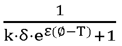
- the heterogeneity degree 1 k ⁇ ⁇ ⁇ e ⁇ ⁇ ⁇ T + 1 of the cathode active material of this application where k is the diffraction peak intensity correction factor, and ⁇ and T are cation correction factors.
- the cathode active material meeting the crystal domain heterogeneity degree has a higher capacity of separating sodium ions and has a higher specific capacity.
- the double crystal domain structure can relieve irreversible transition and interlayer slipping of the structure under a high voltage as massive sodium ions are separated, so that the stability of the material is better enhanced.
- the doping element M is selected from at least one of Li, K, Rb, Be, Mg, Ca, Cu, Sr, and Zn.
- 0.7 ⁇ x ⁇ 0.8, 0.01 ⁇ a ⁇ 0.4, 0.01 ⁇ b ⁇ 0.35, 0.3 ⁇ c ⁇ 0.8, and 0 ⁇ d ⁇ 0.1 Preferably, 0.7 ⁇ x ⁇ 0.8, 0.2 ⁇ a ⁇ 0.25, 0.2b ⁇ 0.25, 0.45 ⁇ c ⁇ 0.55, and 0 ⁇ d ⁇ 0.1.
- a condition that the P2 phase structure is hardly formed as a result of a too high content of nickel and ferric can be avoided.
- x can be, for example, 0.7, 0.75 or 0.8
- a can be, for example, 0.2, 0.225, 0.24 or 0.25
- b can be, for example, 0.2, 0.225, 0.24 or 0.25
- c can be, for example, 0.45, 0.48, 0.5 or 0.55
- d can be, for example, 0, 0.04, 0.05 or 0.1.
- a particle size D50 of the cathode active material is 3-15 ⁇ m.
- the particle size D50 of the cathode active material is 5-10 ⁇ m.
- a specific surface area SSA of the cathode active material is 0.2-2 m 2 /g.
- the specific surface area SSA of the cathode active material is 0.3-0.7 m2/g.
- pH of the cathode active material is 11-13.
- a tap density TD of the cathode active material is greater than 1.6g/cm 3 .
- the tap density TD of the cathode active material is 1.8-2.5 g/cm 3 .
- a mass content of CO 3 2- in the cathode active material is ⁇ 2 wt%, and a mass content of OH - in the cathode material is ⁇ 2 wt%.
- a mass content of water in the cathode active material is ⁇ 0.05 wt%.
- the cathode active material is the layered oxide with the double crystal domain structure, and the cathode active material meeting the crystal domain heterogeneity degree has a higher capacity of separating sodium ions and has a higher specific capacity. Moreover, the double crystal domain structure can relieve irreversible transition and interlayer slipping of the structure under a high voltage as massive sodium ions are separated, so that the stability of the material is better enhanced. The above integrally improves the electrochemical performance of the cathode active material in the technical solution of this application, which facilitates wide application.
- the P2/O3 double crystal domain structure in the cathode active material provides an in-situ sodium supplementing site.
- the damage to the original structure is less, the lattice mismatch is less, and a phenomenon that massive transition metals are dissolved after sodium supplementation is not easily caused.
- this structure can further effectively neutralize the interfacial stress generated by phase change in the charging and discharging processes, thereby reducing side reactions generated as the electrolyte permeates into the structure.
- the surface of the cathode active material with double crystal domain structure has a relatively low air sensitivity characteristic and has excellent processability.
- a method for preparing the cathode active material in an implementation includes the following steps: S10, based on a stoichiometric ratio of Na x NiaFe b Mn c M a O 2 , a sodium salt, a nickel, ferric, and manganese-based precursor, and a precursor of a doping element M are uniformly mixed to obtain a sintered precursor.
- a mass of the sodium salt is 100-110 wt% by stoichiometry of Na needed.
- the sodium salt is selected from at least one of anhydrous sodium carbonate, monohydrated sodium carbonate, sodium carbonate decahydrate, sodium hydrogen carbonate, and sodium sulfate.
- the sodium salt is selected from at least one of anhydrous sodium carbonate, sodium hydrogen carbonate, and sodium sulfate.
- the precursor of the doping element M is selected from at least one of an oxide of the doping element M, a sulfide of the doping element M, a nitride of the doping element M, and a carbonate of the doping element M.
- the sodium, the nickel, ferric, and manganese-based precursor and the precursor of the doping element M are uniformly mixed through mechanical mixing equipment.
- the mechanical mixing equipment is a ball mill, a three-dimensional mixer, a high speed mixer or a VC mixer.
- the sintered precursor obtained in S10 is sintered, and then the precursor is crushed to obtain the cathode active material.
- the preparation method for the cathode active material is simple, and the prepared cathode active material is the layered oxide with the double crystal domain structure, and the cathode active material meeting the crystal domain heterogeneity degree has a higher capacity of separating sodium ions and has a higher specific capacity. Moreover, the double crystal domain structure can relieve irreversible transition and interlayer slipping of the structure under a high voltage as massive sodium ions are separated, so that the stability of the material is better enhanced. The above integrally improves the electrochemical performance of the cathode active material in the technical solution of this application, which facilitates wide application.
- a cathode plate in an implementation includes any one of the above cathode active materials.
- the cathode plate further includes a collector, a conductive additive coated to the collector, and a binder.
- the cathode plate can be prepared by the following steps: the cathode active material, the conductive additive, and the binder are uniformly mixed, then the mixture is coated to the collector, and the mixture is dried to obtain the cathode plate.
- the cathode plate in the technical solution of this application includes the cathode active material.
- the cathode active material is the layered oxide with the double crystal domain structure, and the cathode active material meeting the crystal domain heterogeneity degree has a higher capacity of separating sodium ions and has a higher specific capacity.
- the double crystal domain structure can relieve irreversible transition and interlayer slipping of the structure under a high voltage as massive sodium ions are separated, so that the stability of the material is better enhanced.
- the above integrally improves the electrochemical performance of the cathode active material in the technical solution of this application, so that the electrochemical performance of the cathode plate is improved, which facilitates wide application.
- a sodium ion secondary battery in an implementation includes any one of the above cathode plates.
- the sodium ion secondary battery in this application can be used for large energy storage, household energy storage, a two-wheeled cart, low speed electric automobile equipment.
- the sodium ion secondary battery in the technical solution of this application includes the cathode plate.
- the cathode plate in the technical solution of this application includes the cathode active material.
- the cathode active material is the layered oxide with the double crystal domain structure, and the cathode active material meeting the crystal domain heterogeneity degree has a higher capacity of separating sodium ions and has a higher specific capacity.
- the double crystal domain structure can relieve irreversible transition and interlayer slipping of the structure under a high voltage as massive sodium ions are separated, so that the stability of the material is better enhanced.
- the above integrally improves the electrochemical performance of the cathode active material in the technical solution of this application, so that the electrochemical performance of the sodium ion secondary battery is improved, which facilitates wide application.
- the example provides a cathode active material and a preparation method therefor.
- the preparation includes the following steps:
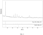
- the cathode active material prepared in example 1 is diffracted by an X ray to obtain FIG. 2 .
- the principle phase of the cathode active material prepared in example 1 is a P2 phase with a space group being P63/mmc
- the secondary phase thereof is an O3 phase with a space group being R-3m
- the example provides a cathode active material and a preparation method therefor.
- the preparation includes the following steps:
- the example provides a cathode active material and a preparation method therefor.
- the preparation includes the following steps:
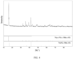
- the cathode active material prepared in example 3 is diffracted by an X ray to obtain FIG. 4 .
- the principle phase of the cathode active material prepared in example 3 is a P2 phase with a space group being P63/mmc
- the secondary phase thereof is an O3 phase with a space group being R-3m
- the peak-to-intensity ratio of the diffraction peak corresponding to the crystal face of its O3 phase (104) and the diffraction peak corresponding to the crystal face of its P2 phase (002) after removing the background 0.45
- the example provides a cathode active material and a preparation method therefor.
- the preparation includes the following steps:
- the cathode active material prepared in example 4 is a secondary agglomerate.
- pH 12.4.
- the example provides a cathode active material and a preparation method therefor.
- the preparation includes the following steps:
- the example provides a cathode active material and a preparation method therefor.
- the preparation includes the following steps:
- the example provides a cathode active material and a preparation method therefor.
- the preparation includes the following steps:
- the example provides a cathode active material and a preparation method therefor.
- the preparation includes the following steps:
- the cathode active material prepared in example 8 is a secondary agglomerate.
- pH 12.4.
- the example provides a cathode active material and a preparation method therefor.
- the preparation includes the following steps:
- the cathode active material prepared in example 9 is a secondary agglomerate.
- pH 12.4.
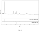
- the cathode active material prepared in comparative example 1 is diffracted by an X ray to obtain FIG. 5 .
- the principle phase of the cathode active material prepared in comparative example 1 is a P2 phase with a space group being P63/mmc
- the secondary phase thereof is an O3 phase with a space group being R-3m
- the comparative example provides a cathode active material and a preparation method therefor.
- the preparation includes the following steps:
- the comparative example provides a cathode active material and a preparation method therefor.
- the preparation includes the following steps:
- the cathode active materials prepared in examples 1-9 and comparative examples 1-3, PVDF, and conductive carbon dispersed in an NMP solvent are coated to aluminum foil collectors and dried to prepare the cathode plates, and then the cathode plates, sodium sheets, glass fiber diaphragms, washers, reeds, and an NaPF6-DIGLYME electrolyte are prepared into button cells according to a button cell assembly standard operation procedure. Tested by a Neware detection channel, charging and discharging curves at a rate of 2.0-4.1V 0.1C can be obtained.
- the charging and discharging curves of the button cells prepared by the cathode active materials prepared in examples 1 and 3 and comparative example 1 are shown in FIGs. 6-8 .
Landscapes
- Chemical & Material Sciences (AREA)
- Chemical Kinetics & Catalysis (AREA)
- Electrochemistry (AREA)
- General Chemical & Material Sciences (AREA)
- Engineering & Computer Science (AREA)
- Inorganic Chemistry (AREA)
- Manufacturing & Machinery (AREA)
- Materials Engineering (AREA)
- Organic Chemistry (AREA)
- Battery Electrode And Active Subsutance (AREA)
- Secondary Cells (AREA)
Abstract
Description
- This application claims the priority of Chinese patent application for invention No.
CN 202311151572.5, filed September 7, 2023 - This application relates to the technical field of sodium ion batteries, and particularly relates to a cathode active material and a preparation method therefor and an application thereof.
- Due to restrictions of factors such as shortage of conventional fossil energy and energy safety and enhancement on protection concept of the ecological environment, sustainable development and utilization and storage of energy sources are highly valued by countries in the world. In various energy storage systems, thanks to advantages of long service life, low cost, little investment, easy installation, and the like, an electrochemical energy storage system (EES) is considered an effective method to balance cycle performance of renewable energy sources. Secondary batteries in electrochemical energy storage have a huge potential. Lithium ion batteries dominate the energy storage market as a result of high theoretical specific capacity and specific energy density. However, due to limited reserve and uneven distribution of lithium (Li) resources and consumption of lithium in multiple aspects, restricted by objective factors such as lithium extraction technology, geographical environment, and traffic condition, there still exists a bottleneck in lithium resources in the power battery filed. Undersupply of lithium resources results in rise in price. Continuous rise in lithium price will accelerate a process of seeking for substitute goods with higher cost performance by enterprises. Besides reducing carbon emission and solving the environmental problems, the object to develop new energy automobiles energetically in China is also to reduce dependency on import of conventional fossil fuel. If the resource bottleneck problem cannot be solved, a certain discount will be given to meaning of developing electric automobiles. Besides the lithium resources, other links of lithium batteries, for example, cobalt and nickel, also face the problems of import dependence and large fluctuation of price. To alleviate the problem, a concept of replacing lithium with elements with large abundance such as sodium (Na), potassium (K), magnesium (Mg), Aluminum (Al), and calcium (Ca) has been proposed in the related art to prepare a new generation of secondary ion batteries which are low in cost and environmental-friendly. To develop sodium ion batteries is strategically significant at the country level. Sodium ion batteries have been focused and supported by increasingly more countries.
- A sodium-based layered oxide cathode material is one of the most critical materials for sodium ion batteries. Similar to lithium cobalt oxides and ternary structures of lithium ion batteries, the layered oxide structure has a good ion channel, with probably a certain dead end in cycle performance, but the average maturity is relatively high. A transition metal oxide NaXMeO2 is an embedded or intercalated compound. It has a higher specific discharge capacity theoretically but poor cycle performance. By introducing active or inert elements for doping or substituting, the defect can be improved. The type of the layered oxide mainly includes O2 type, O3 type, P2 type, and P3 type, where O or P represents the position of Na+ in an octahedron or a prism, and figures represent repeatedly arranged units of different oxide layers.O3 type and P2 type are relatively stable phase structures. There is much work conducted for these two types. Compared with its electrochemical performance, although there are some differences, in a word, a transition metal oxide system is still a route with relatively high maturity at present.
- The types in the layered oxide materials of existing sodium ion batteries are significant in defect (the O3 type material is high in capacity, low in first effect, and poor in cycle performance, and often has problems of massive aerogenesis, metal dissolution, and structure evolution in a total battery application process; the P2 type material is relatively low in initial charge capacity, but is good in cycle performance and rate performance; and the P3 type material is low in capacity, poor in cycle, high in working voltage, and the like), so that the comprehensive performance is poor. The types are hardly combined together organically. Core-shell coating and direct blending methods in conventional methods often introduce new electrochemical inert substances or have new two-phase interfacial problem, which results in poor electrochemical performance of the material, thereby bringing resistance to industrial application of the sodium ion batteries.
- On this basis, to improve the electrochemical performance of a cathode material, it is necessary to provide a cathode active material and a preparation method therefor and an application thereof.
- A chemical formula of the cathode active material is NaxNiaFebMncMaO2, where a+b+c+d=1, 0.7≤x<0.9, 0.01≤a≤0.5, 0.01≤b≤0.4, 0.2≤c<1, 0≤d≤0.2; a doping element M is a metal element, a valence state of which is less than or equal to bivalence;
- the cathode active material is a layered oxide with a double crystal domain structure; the double crystal domain structure includes a P2 principal phase and an O3 heterogeneous phase; the crystal domain of the cathode active material meets: 0<ω≤0.48,


- The cathode active material is the layered oxide with the double crystal domain structure, and the cathode active material meeting the crystal domain heterogeneity degree has a higher capacity of separating sodium ions and has a higher specific capacity. Moreover, the double crystal domain structure can relieve irreversible transition and interlayer slipping of the structure under a high voltage as massive sodium ions are separated, so that the stability of the material is better enhanced. The above integrally improves the electrochemical performance of the cathode active material in the technical solution of this application, which facilitates wide application.
- In a feasible implementation, in the chemical formula NaxNiaFebMncMaO2 of the cathode active material, the doping element M is selected from at least one of Li, K, Rb, Be, Mg, Ca, Cu, Sr, and Zn.
- In a feasible implementation, in the chemical formula NaxNiaFebMncMaO2 of the cathode active material, 0.7≤x≤0.8, 0.01≤a≤0.4, 0.01≤b≤0.35, 0.3≤c<0.8, and 0≤d≤0.1.
- In a feasible implementation, in an X-ray diffraction result of the layered oxide, a peak position of the diffraction peak (002) of the P2 phase is present at 2θ=15.80±0.5°, and a peak position of the diffraction peak (104) of the O3 phase is present at 2θ=41.5±0.5°;
- a particle size D50 of the cathode active material is 3-15 µm;
- a specific surface area of the cathode active material is 0.2-2 m2/g;
- pH of the cathode active material is 11-13;
- a tap density of the cathode active material is greater than 1.6 g/cm3;
- a mass content of CO3 2- in the cathode active material is ≤2 wt%, and a mass content of OH- in the cathode material is ≤2wt%; and
- a mass content of water in the cathode active material is ≤0.05 wt%.
- A method for preparing any one of the above cathode active materials, including the following steps:
- based on a stoichiometric ratio of NaxNiaFebMncMaO2, uniformly mixing a sodium salt, a nickel, ferric, and manganese-based precursor, and a precursor of a doping element M to obtain a sintered precursor; and
- sintering the sintered precursor, and then crushing the same to obtain the cathode active material.
- The preparation method for the cathode active material is simple, and the prepared cathode active material is the layered oxide with the double crystal domain structure, and the cathode active material meeting the crystal domain heterogeneity degree has a higher capacity of separating sodium ions and has a higher specific capacity. Moreover, the double crystal domain structure can relieve irreversible transition and interlayer slipping of the structure under a high voltage as massive sodium ions are separated, so that the stability of the material is better enhanced. The above integrally improves the electrochemical performance of the cathode active material in the technical solution of this application, which facilitates wide application.
- In a feasible implementation, the nickel, ferric, and manganese-based precursor includes an oxide or hydroxide of nickel, an oxide or hydroxide of ferric, and an oxide or hydroxide of manganese; or the nickel, ferric, and manganese-based precursor is a nickel, ferric, and manganese-based hydroxide precursor prepared by a coprecipitation method; and
the precursor of the doping element M is selected from at least one of an oxide of the doping element M, a sulfide of the doping element M, a nitride of the doping element M, and a carbonate of the doping element M. - In a feasible implementation, a mass of the sodium salt is 100-110 wt% by stoichiometry of Na needed; and
the sodium salt is selected from at least one of anhydrous sodium carbonate, monohydrated sodium carbonate, sodium carbonate decahydrate, sodium hydrogen carbonate, and sodium sulfate. - In a feasible implementation, in an operation of sintering the sintered precursor, a sintering temperature is 800-950°C, a sintering time is 12-24 h, and a sintering atmosphere is selected from at least one of air and oxygen.
- A cathode plate, including any one of the above cathode active materials.
- The cathode plate in the technical solution of this application includes the cathode active material. The cathode active material is the layered oxide with the double crystal domain structure, and the cathode active material meeting the crystal domain heterogeneity degree has a higher capacity of separating sodium ions and has a higher specific capacity. Moreover, the double crystal domain structure can relieve irreversible transition and interlayer slipping of the structure under a high voltage as massive sodium ions are separated, so that the stability of the material is better enhanced. The above integrally improves the electrochemical performance of the cathode active material in the technical solution of this application, so that the electrochemical performance of the cathode plate is improved, which facilitates wide application.
- A sodium ion secondary battery, including the cathode plate.
- The sodium ion secondary battery in the technical solution of this application includes the cathode plate. The cathode plate in the technical solution of this application includes the cathode active material. The cathode active material is the layered oxide with the double crystal domain structure, and the cathode active material meeting the crystal domain heterogeneity degree has a higher capacity of separating sodium ions and has a higher specific capacity. Moreover, the double crystal domain structure can relieve irreversible transition and interlayer slipping of the structure under a high voltage as massive sodium ions are separated, so that the stability of the material is better enhanced. The above integrally improves the electrochemical performance of the cathode active material in the technical solution of this application, so that the electrochemical performance of the sodium ion secondary battery is improved, which facilitates wide application.
-
-
FIG. 1 is an SEM image of a cathode active material of a sodium ion secondary battery prepared in an example 1 of this application; -
FIG. 2 is an XRD diffraction image of the cathode active material of the sodium ion secondary battery prepared in the example 1 of this application; -
FIG. 3 is an SEM image of a cathode active material of a sodium ion secondary battery prepared in an example 3 of this application; -
FIG. 4 is an XRD diffraction image of the cathode active material of the sodium ion secondary battery prepared in the example 3 of this application; -
FIG. 5 is an XRD diffraction image of the cathode active material of the sodium ion secondary battery prepared in a comparative example 1 of this application; -
FIG. 6 is a charging and discharging curve graph of a button cell made of the cathode active material of the sodium ion secondary battery prepared in the example 1 of this application at a rate of 2.0-4.1V 0.1C; -
FIG. 7 is a charging and discharging curve graph of a button cell made of the cathode active material of the sodium ion secondary battery prepared in the example 3 of this application at a rate of 2.0-4.1V 0.1C; -
FIG. 8 is a charging and discharging curve graph of a button cell made of the cathode active material of the sodium ion secondary battery prepared in the example 1 of this application at a rate of 2.0-4.1 V 0.1C. - In order to enable the above objects, features, and advantages of this application to be more apparent and easily understood, specific embodiments of this application will be described in detail below with reference to the accompanying drawings. Many specific details are set forth in the following description to facilitate full understanding of this application. However, this application can be practiced in many other ways than those described herein, and persons skilled in the art may make similar modifications without departing from the spirit of this application, and therefore this application is not to be limited by the specific embodiments disclosed below.
- Unless defined otherwise, all technical and scientific terms used herein have the same meaning as commonly understood by persons of ordinary skill in the art to which this application belongs. The terms used herein in the specification of this application are for the purpose of describing specific embodiments only and are not intended to limit this application. As used herein, the term "and/or" includes any and all combinations of one or more relevant listed items.
- A chemical formula of a cathode active material in an implementation is NaxNiaFebMncMaO2, where a+b+c+d=1, 0.7≤x<0.9, 0.01≤a≤0.5, 0.01≤b≤0.4, 0.2≤c<1, 0≤d≤0.2; a doping element M is a metal element, a valence state of which is less than or equal to bivalence.
- The cathode active material is a layered oxide with a double crystal domain structure; the double crystal domain structure includes a P2 principal phase and an O3 heterogeneous phase; the crystal domain heterogeneity degree of the cathode active material meets: 0<ω≤0.48, ω =


- As far as a mixed phase material is concerned, respective characteristic peak positions can be observed usually through the X-ray diffraction pattern. However, to represent the content ratio directly through a peak-to-intensity ratio is often inaccurate. According to differences of degree of crystallinity of different phase structures, there is a difference of coefficient between the peak-to-intensity ratio and the content ratio, i.e., Mp/MO=k×Ip/IO. Therefore, the proportion (heterogeneity degree) of the O phase in the mixed system is MO/(MP+MO), i.e.,


- Based on the above implementation, in the chemical formula NaxNiaFebMncMaO2 of the cathode active material, the doping element M is selected from at least one of Li, K, Rb, Be, Mg, Ca, Cu, Sr, and Zn.
- Based on the above implementation, in the chemical formula NaxNiaFebMncMaO2 of the cathode active material, 0.7≤x≤0.8, 0.01≤a≤0.4, 0.01≤b≤0.35, 0.3≤c<0.8, and 0≤d≤0.1. Preferably, 0.7≤x≤0.8, 0.2≤a≤0.25, 0.2b≤0.25, 0.45≤c≤0.55, and 0≤d≤0.1.In this case, a condition that the P2 phase structure is hardly formed as a result of a too high content of nickel and ferric can be avoided. x can be, for example, 0.7, 0.75 or 0.8, a can be, for example, 0.2, 0.225, 0.24 or 0.25, b can be, for example, 0.2, 0.225, 0.24 or 0.25, c can be, for example, 0.45, 0.48, 0.5 or 0.55, and d can be, for example, 0, 0.04, 0.05 or 0.1.
- Based on the above implementation, in an X-ray diffraction result of the layered oxide, a peak position of the diffraction peak (002) of the P2 phase is present at 2θ=15.80±0.5°, and a peak position of the diffraction peak (104) of the O3 phase is present at 2θ=41.5±0.5°. Preferably, in an X-ray diffraction result of the layered oxide, a peak position of the diffraction peak (002) of the P2 phase is present at 2θ=15.80±0.2°, and a peak position of the diffraction peak (104) of the O3 phase is present at 2θ=41.5±0.2°.In this case, the less the deviation of the peak position is, the more accurate the test is.
- Based on the above implementation, a particle size D50 of the cathode active material is 3-15 µm. Preferably, the particle size D50 of the cathode active material is 5-10 µm.
- Based on the above implementation, a specific surface area SSA of the cathode active material is 0.2-2 m2/g. Preferably, the specific surface area SSA of the cathode active material is 0.3-0.7 m2/g.
- Based on the above implementation, pH of the cathode active material is 11-13.
- Based on the above implementation, a tap density TD of the cathode active material is greater than 1.6g/cm3. Preferably, the tap density TD of the cathode active material is 1.8-2.5 g/cm3.
- Based on the above implementation, a mass content of CO3 2- in the cathode active material is ≤2 wt%, and a mass content of OH- in the cathode material is ≤2 wt%.
- Based on the above implementation, a mass content of water in the cathode active material is ≤0.05 wt%.
- The cathode active material is the layered oxide with the double crystal domain structure, and the cathode active material meeting the crystal domain heterogeneity degree has a higher capacity of separating sodium ions and has a higher specific capacity. Moreover, the double crystal domain structure can relieve irreversible transition and interlayer slipping of the structure under a high voltage as massive sodium ions are separated, so that the stability of the material is better enhanced. The above integrally improves the electrochemical performance of the cathode active material in the technical solution of this application, which facilitates wide application.
- In addition, compared with a pure P2 phase structure, the P2/O3 double crystal domain structure in the cathode active material provides an in-situ sodium supplementing site. In the charging and discharging processes, the damage to the original structure is less, the lattice mismatch is less, and a phenomenon that massive transition metals are dissolved after sodium supplementation is not easily caused. Moreover, thanks to a local confinement effect, irreversible transition of a small amount of O3 crystal domains in the charging and discharging processes is inhibited. Further, this structure can further effectively neutralize the interfacial stress generated by phase change in the charging and discharging processes, thereby reducing side reactions generated as the electrolyte permeates into the structure. Moreover, different from conventional P2/O3 phase blended/core-shell structure, the surface of the cathode active material with double crystal domain structure has a relatively low air sensitivity characteristic and has excellent processability.
- A method for preparing the cathode active material in an implementation includes the following steps:
S10, based on a stoichiometric ratio of NaxNiaFebMncMaO2, a sodium salt, a nickel, ferric, and manganese-based precursor, and a precursor of a doping element M are uniformly mixed to obtain a sintered precursor. - In a feasible implementation, a mass of the sodium salt is 100-110 wt% by stoichiometry of Na needed.
- In a feasible implementation, the sodium salt is selected from at least one of anhydrous sodium carbonate, monohydrated sodium carbonate, sodium carbonate decahydrate, sodium hydrogen carbonate, and sodium sulfate. Preferably, the sodium salt is selected from at least one of anhydrous sodium carbonate, sodium hydrogen carbonate, and sodium sulfate.
- In a feasible implementation, the nickel, ferric, and manganese-based precursor includes an oxide or hydroxide of nickel, an oxide or hydroxide of ferric, and an oxide or hydroxide of manganese.
- In a feasible implementation, the nickel, ferric, and manganese-based precursor is a nickel, ferric, and manganese-based hydroxide precursor prepared by a coprecipitation method. In this case, the transition metal elements are advantageously distributed uniformly to avoid agglomeration of the principle element material in the mixing structure and prevent the locally uncontrollable poly-crystal domain structure from affecting the performance of the material as a result of segregation of the elements in the sintering process.
- In a feasible implementation, the precursor of the doping element M is selected from at least one of an oxide of the doping element M, a sulfide of the doping element M, a nitride of the doping element M, and a carbonate of the doping element M.
- In a feasible implementation, the sodium, the nickel, ferric, and manganese-based precursor and the precursor of the doping element M are uniformly mixed through mechanical mixing equipment. Further, the mechanical mixing equipment is a ball mill, a three-dimensional mixer, a high speed mixer or a VC mixer.
- S20, the sintered precursor obtained in S10 is sintered, and then the precursor is crushed to obtain the cathode active material.
- In a feasible implementation, in an operation of sintering the sintered precursor, a sintering temperature is 800-950°C, a sintering time is 12-24 h, and a sintering atmosphere is selected from at least one of air and oxygen. Preferably, the sintering temperature is 850-900°C, the sintering time is 12-20 h, and the sintering atmosphere is oxygen.
- In a feasible implementation, the precursor is crushed by crushing equipment and is screened to obtain the cathode active material. Further, the crushing equipment is selected from at least one of a double roll crusher, a ball mill, a stone mortar mill, and a pneumatic cracker.
- The preparation method for the cathode active material is simple, and the prepared cathode active material is the layered oxide with the double crystal domain structure, and the cathode active material meeting the crystal domain heterogeneity degree has a higher capacity of separating sodium ions and has a higher specific capacity. Moreover, the double crystal domain structure can relieve irreversible transition and interlayer slipping of the structure under a high voltage as massive sodium ions are separated, so that the stability of the material is better enhanced. The above integrally improves the electrochemical performance of the cathode active material in the technical solution of this application, which facilitates wide application.
- A cathode plate in an implementation includes any one of the above cathode active materials. The cathode plate further includes a collector, a conductive additive coated to the collector, and a binder.
- The cathode plate can be prepared by the following steps: the cathode active material, the conductive additive, and the binder are uniformly mixed, then the mixture is coated to the collector, and the mixture is dried to obtain the cathode plate.
- The cathode plate in the technical solution of this application includes the cathode active material. The cathode active material is the layered oxide with the double crystal domain structure, and the cathode active material meeting the crystal domain heterogeneity degree has a higher capacity of separating sodium ions and has a higher specific capacity. Moreover, the double crystal domain structure can relieve irreversible transition and interlayer slipping of the structure under a high voltage as massive sodium ions are separated, so that the stability of the material is better enhanced. The above integrally improves the electrochemical performance of the cathode active material in the technical solution of this application, so that the electrochemical performance of the cathode plate is improved, which facilitates wide application.
- A sodium ion secondary battery in an implementation includes any one of the above cathode plates. The sodium ion secondary battery in this application can be used for large energy storage, household energy storage, a two-wheeled cart, low speed electric automobile equipment.
- The sodium ion secondary battery in the technical solution of this application includes the cathode plate. The cathode plate in the technical solution of this application includes the cathode active material. The cathode active material is the layered oxide with the double crystal domain structure, and the cathode active material meeting the crystal domain heterogeneity degree has a higher capacity of separating sodium ions and has a higher specific capacity. Moreover, the double crystal domain structure can relieve irreversible transition and interlayer slipping of the structure under a high voltage as massive sodium ions are separated, so that the stability of the material is better enhanced. The above integrally improves the electrochemical performance of the cathode active material in the technical solution of this application, so that the electrochemical performance of the sodium ion secondary battery is improved, which facilitates wide application.
- With reference to the above implemented content, to make the technical solution of this application more specific, clear and easy to understand, examples are given to the technical solution of this application. But it needs to be noted that the content to be protected by this application is not limited to the examples below.
- The example provides a cathode active material and a preparation method therefor. The preparation includes the following steps:
- 56.3 g of anhydrous sodium carbonate and 130.2 g of a nickel, ferric, and manganese-based precursor (the molar ratio of Ni: Fe: Mn was 1: 1: 2) prepared by a coprecipitation method were uniformly mixed through a high speed mixer to obtain a sintered precursor; and
- the sintered precursor was put in an oven type atmosphere furnace for high-temperature calcining at 850°C in an oxygen atmosphere for 14 h, and the sintered precursor was crushed and screened to obtain a layered oxide material Na0.7Ni0.25Fe0.25Mn0.5O2.
- The cathode active material prepared in example 1 is characterized by a scanning electron microscope to obtain
FIG. 1 . It can be seen fromFIG. 1 that the cathode active material prepared in example 1 is a secondary agglomerate. After the test, the particle size D50 of the cathode active material is =6.8 µm, the specific surface area SSA is =0.6 m2/g, the tap density TD is =1.9 g/cm3, and pH is =12.7. - The cathode active material prepared in example 1 is diffracted by an X ray to obtain
FIG. 2 . It can be seen fromFIG. 2 that the principle phase of the cathode active material prepared in example 1 is a P2 phase with a space group being P63/mmc, the secondary phase thereof is an O3 phase with a space group being R-3m, and the peak-to-intensity ratio of the diffraction peak corresponding to the crystal face of its O3 phase (104) and the diffraction peak corresponding to the crystal face of its P2 phase (002) after removing the background is 0.05, δ=Ip/IO=20. Specifically, the cation potential

- The example provides a cathode active material and a preparation method therefor. The preparation includes the following steps:
- 56.3 g of anhydrous sodium carbonate and 26.97g of nickel oxide, 28.85 g of ferric oxide, and 62.82 g of manganese oxide were uniformly mixed through a high speed mixer to obtain a sintered precursor; and
- the sintered precursor was put in an oven type atmosphere furnace for high-temperature calcining at 870°C in an oxygen atmosphere for 12 h, and the sintered precursor was crushed and screened to obtain a layered oxide material Na0.7Ni0.25Fe0.25Mn0.5O2.
- The cathode active material prepared in example 2 is a secondary agglomerate. After the test, the particle size D50 of the cathode active material is =7.2 µm, the specific surface area SSA is =0.5 m2/g, the tap density TD is =1.9 g/cm3, and pH is =12.8.
- The principle phase of the cathode active material prepared in example 2 is a P2 phase with a space group being P63/mmc, the secondary phase thereof is an O3 phase with a space group being R-3m, and the peak-to-intensity ratio of the diffraction peak corresponding to the crystal face of its O3 phase (104) and the diffraction peak corresponding to the crystal face of its P2 phase (002) after removing the background is 0.06, δ=Ip/IO=16.7. Specifically, the cation potential


- The example provides a cathode active material and a preparation method therefor. The preparation includes the following steps:
- 61.56 g of anhydrous sodium carbonate, 130.2 g of a nickel, ferric, and manganese-based precursor (the molar ratio of Ni: Fe: Mn was 1: 1: 2) prepared by a coprecipitation method, and a precursor of doping elements (0.75 mol% of lithium carbonate and 2 mol% of magnesium oxide) were uniformly mixed through a high speed mixer to obtain a sintered precursor; and
- the sintered precursor was put in an oven type atmosphere furnace for high-temperature calcining at 850°C in an oxygen atmosphere for 12 h, and the sintered precursor was crushed and screened to obtain a layered oxide material Na0.75Ni0.24Fe0.24Mn0.48Li0.015Mg0.025O2.
- The cathode active material prepared in example 3 is characterized by a scanning electron microscope to obtain
FIG. 3 . It can be seen fromFIG. 3 that the cathode active material prepared in example 3 is a secondary agglomerate. After the test, the particle size D50 of the cathode active material is =6.4µm, the specific surface area SSA is =0.6 m2/g, the tap density TD is =1.9 g/cm3, and pH is =12.8. - The cathode active material prepared in example 3 is diffracted by an X ray to obtain
FIG. 4 . It can be seen fromFIG. 4 that the principle phase of the cathode active material prepared in example 3 is a P2 phase with a space group being P63/mmc, the secondary phase thereof is an O3 phase with a space group being R-3m, and the peak-to-intensity ratio of the diffraction peak corresponding to the crystal face of its O3 phase (104) and the diffraction peak corresponding to the crystal face of its P2 phase (002) after removing the background is 0.45, δ=Ip/IO=2.22. Specifically, the cation potential of the cathode active material is
- The example provides a cathode active material and a preparation method therefor. The preparation includes the following steps:
- 61.04 g of anhydrous sodium carbonate, 33.47 g of nickelous hydroxide, 28.85 g of ferric oxide, 64.27 g of manganese hydroxide, and a precursor of doping elements (0.75 mol% of lithium carbonate and 2.5 mol% of magnesium oxide) were uniformly mixed through a high speed mixer to obtain a sintered precursor; and
- the sintered precursor was put in an oven type atmosphere furnace for high-temperature calcining at 890°C in an oxygen atmosphere for 12 h, and the sintered precursor was crushed and screened to obtain a layered oxide material Na0.75Ni0.24Fe0.24Mn0.48Li0.015Mg0.025O2.
- The cathode active material prepared in example 4 is a secondary agglomerate. After the test, the particle size D50 of the cathode active material is =8 µm, the specific surface area SSA is =0.4 m2/g, the tap density TD is =2.0 g/cm3, and pH is =12.4.
- The principle phase of the cathode active material prepared in example 4 is a P2 phase with a space group being P63/mmc, the secondary phase thereof is an O3 phase with a space group being R-3m, and the peak-to-intensity ratio of the diffraction peak corresponding to the crystal face of its O3 phase (104) and the diffraction peak corresponding to the crystal face of its P2 phase (002) after removing the background is 0.43, δ=Ip/IO=2.32. Specifically, the cation potential of the cathode active material is

- The example provides a cathode active material and a preparation method therefor. The preparation includes the following steps:
- 62.79 g of anhydrous sodium carbonate, 130.2 g of a nickel, ferric, and manganese-based precursor (the molar ratio of Ni: Fe: Mn was 1: 1: 2) prepared by a coprecipitation method, and a precursor of doping elements (1 mol% of potassium carbonate and 2 mol% of magnesium oxide) were uniformly mixed through a high speed mixer to obtain a sintered precursor; and
- the sintered precursor was put in an oven type atmosphere furnace for high-temperature calcining at 860°C in an oxygen atmosphere for 16 h, and the sintered precursor was crushed and screened to obtain a layered oxide material Na0.75Ni0.24Fe0.24Mn0.48K0.02Mg0.02O2.
- The cathode active material prepared in example 5 is a secondary agglomerate. After the test, the particle size D50 of the cathode active material is =6.8 µm, the specific surface area SSA is =0.3 m2/g, the tap density TD is =1.85 g/cm3, and pH is =12.5.
- The principle phase of the cathode active material prepared in example 5 is a P2 phase with a space group being P63/mmc, the secondary phase thereof is an O3 phase with a space group being R-3m, and the peak-to-intensity ratio of the diffraction peak corresponding to the crystal face of its O3 phase (104) and the diffraction peak corresponding to the crystal face of its P2 phase (002) after removing the background is 0.46, δ=Ip/IO=2.17. Specifically, the cation potential of the cathode active material is

- The example provides a cathode active material and a preparation method therefor. The preparation includes the following steps:
- 84.11 g of sodium sulfate, 26.97 g of nickel oxide, 28.85 g of ferric oxide, 64.27 g of manganese hydroxide, and a precursor of doping elements (1 mol% of potassium sulfide and 2 mol% of magnesium carbonate) were uniformly mixed through a high speed mixer to obtain a sintered precursor; and
- the sintered precursor was put in an oven type atmosphere furnace for high-temperature calcining at 900°C in an oxygen atmosphere for 13 h, and the sintered precursor was crushed and screened to obtain a layered oxide material Na0.75Ni0.24Fe0.24Mn0.48K0.02Mg0.02O2.
- The cathode active material prepared in example 6 is a secondary agglomerate. After the test, the particle size D50 of the cathode active material is =9 µm, the specific surface area SSA is =0.4 m2/g, the tap density TD is =2.0 g/cm3, and pH is =12.5.
- The principle phase of the cathode active material prepared in example 6 is a P2 phase with a space group being P63/mmc, the secondary phase thereof is an O3 phase with a space group being R-3m, and the peak-to-intensity ratio of the diffraction peak corresponding to the crystal face of its O3 phase (104) and the diffraction peak corresponding to the crystal face of its P2 phase (002) after removing the background is 0.47, δ=Ip/IO=2.13. Specifically, the cation potential of the cathode active material is

- The example provides a cathode active material and a preparation method therefor. The preparation includes the following steps:
- 66.99 g of anhydrous sodium carbonate, 130.2 g of a nickel, ferric, and manganese-based precursor (the molar ratio of Ni: Fe: Mn was 1: 1: 2) prepared by a coprecipitation method, and a precursor of doping elements (5mol% of copper oxide and 5mol% of magnesium oxide) were uniformly mixed through a high speed mixer to obtain a sintered precursor; and
- the sintered precursor was put in an oven type atmosphere furnace for high-temperature calcining at 800°C in an air atmosphere for 18 h, and the sintered precursor was crushed and screened to obtain a layered oxide material Na0.75Ni0.225Fe0.225Mn0.45Cu0.05Mg0.05O2.
- The cathode active material prepared in example 7 is a secondary agglomerate. After the test, the particle size D50 of the cathode active material is =9.2 µm, the specific surface area SSA is =0.36 m2/g, the tap density TD is =1.9 g/cm3, and pH is =12.3.
- The principle phase of the cathode active material prepared in example 7 is a P2 phase with a space group being P63/mmc, the secondary phase thereof is an O3 phase with a space group being R-3m, and the peak-to-intensity ratio of the diffraction peak corresponding to the crystal face of its O3 phase (104) and the diffraction peak corresponding to the crystal face of its P2 phase (002) after removing the background is 0.36, δ=Ip/IO=2.78. Specifically, the cation potential of the cathode active material is

- The example provides a cathode active material and a preparation method therefor. The preparation includes the following steps:
- 89.04 g of anhydrous sodium carbonate, 29.88 g of nickel oxide, 28.8 g of ferrous oxide, 100.1 g of manganese oxide, and a precursor of doping elements (2.5 mol% of calcium hydroxide and 2.5 mol% of strontium hydroxide) were uniformly mixed through a high speed mixer to obtain a sintered precursor; and
- the sintered precursor was put in an oven type atmosphere furnace for high-temperature calcining at 820°C in an air atmosphere for 24 h, and the sintered precursor was crushed and screened to obtain a layered oxide material Na0.8Ni0.2Fe0.2Mn0.55Ca0.025Sr0.025O2.
- The cathode active material prepared in example 8 is a secondary agglomerate. After the test, the particle size D50 of the cathode active material is =10.4 µm, the specific surface area SSA is =0.38 m2/g, the tap density TD is =2.0 g/cm3, and pH is =12.4.
- The principle phase of the cathode active material prepared in example 8 is a P2 phase with a space group being P63/mmc, the secondary phase thereof is an O3 phase with a space group being R-3m, and the peak-to-intensity ratio of the diffraction peak corresponding to the crystal face of its O3 phase (104) and the diffraction peak corresponding to the crystal face of its P2 phase (002) after removing the background is 0.24, δ=Ip/IO=7.143. Specifically, the cation potential of the cathode active material is

- The example provides a cathode active material and a preparation method therefor. The preparation includes the following steps:
- 56.61 g of anhydrous sodium carbonate, 130.2 g of a nickel, ferric, and manganese-based precursor (the molar ratio of Ni: Fe: Mn was 1: 1: 2) prepared by a coprecipitation method, and a precursor of doping elements (1 mol% of zinc oxide) were uniformly mixed through a high speed mixer to obtain a sintered precursor; and
- the sintered precursor was put in an oven type atmosphere furnace for high-temperature calcining at 850°C in an air atmosphere for 16 h, and the sintered precursor was crushed and screened to obtain a layered oxide material Na0.7Ni0.248Fe0.248Mn0.494Zn0.01O2.
- The cathode active material prepared in example 9 is a secondary agglomerate. After the test, the particle size D50 of the cathode active material is =8.2 µm, the specific surface area SSA is =0.46 m2/g, the tap density TD is =1.95 g/cm3, and pH is =12.4.
- The principle phase of the cathode active material prepared in example 9 is a P2 phase with a space group being P63/mmc, the secondary phase thereof is an O3 phase with a space group being R-3m, and the peak-to-intensity ratio of the diffraction peak corresponding to the crystal face of its O3 phase (104) and the diffraction peak corresponding to the crystal face of its P2 phase (002) after removing the background is 0.15, δ=Ip/IO=6.67. Specifically, the cation potential of the cathode active material is

- The comparative example provides a cathode active material and a preparation method therefor. The preparation includes the following steps:
- 60.3 g of anhydrous sodium carbonate and 130.2 g of a nickel, ferric, and manganese-based precursor (the molar ratio of Ni: Fe: Mn was 1: 1: 2) prepared by a coprecipitation method were uniformly mixed through a high speed mixer to obtain a sintered precursor; and
- the sintered precursor was put in an oven type atmosphere furnace for high-temperature calcining at 850°C in an oxygen atmosphere for 14 h, and the sintered precursor was crushed and screened to obtain a layered oxide material Na0.75Ni0.25Fe0.25Mn0.5O2.
- The cathode active material prepared in comparative example 1 is diffracted by an X ray to obtain
FIG. 5 . It can be seen fromFIG. 5 that the principle phase of the cathode active material prepared in comparative example 1 is a P2 phase with a space group being P63/mmc, the secondary phase thereof is an O3 phase with a space group being R-3m, and the peak-to-intensity ratio of the diffraction peak corresponding to the crystal face of its O3 phase (104) and the diffraction peak corresponding to the crystal face of its P2 phase (002) after removing the background is 0.48, δ=Ip/IO=2.083. Specifically, the cation potential of the cathode active material is
- The comparative example provides a cathode active material and a preparation method therefor. The preparation includes the following steps:
- 74.2 g of anhydrous sodium carbonate, 44.82 g of nickel oxide, 31.96 g of ferric oxide, 52.2 g of manganese oxide, and a precursor of doping elements (20 mol% of tin oxide) were uniformly mixed through a high speed mixer to obtain a sintered precursor; and
- the sintered precursor was put in an oven type atmosphere furnace for high-temperature calcining at 850°C in an oxygen atmosphere for 16 h, and the sintered precursor was crushed and screened to obtain a layered oxide material Na0.67Ni0.3Fe0.2Mn0.3Sn0.2O2.
- The principle phase of the cathode active material prepared in comparative example 2 is an O3 phase with a space group being R-3m, the secondary phase thereof is a P2 phase with a space group being P63/mmc, and the peak-to-intensity ratio of the diffraction peak corresponding to the crystal face of its O3 phase (104) and the diffraction peak corresponding to the crystal face of its P2 phase (002) after removing the background is 1.56, δ=Ip/IO=0.641.
- Specifically, the cation potential of the cathode active material is

- The comparative example provides a cathode active material and a preparation method therefor. The preparation includes the following steps:
- 72.35 g of anhydrous sodium carbonate and 130.2 g of a nickel, ferric, and manganese-based precursor (the molar ratio of Ni: Fe: Mn was 1: 1: 2) prepared by a coprecipitation method were uniformly mixed through a high speed mixer to obtain a sintered precursor; and
- the sintered precursor was put in an oven type atmosphere furnace for high-temperature calcining at 870°C in an oxygen atmosphere for 14 h, and the sintered precursor was crushed and screened to obtain a layered oxide material Na0.9Ni0.25Fe0.25Mn0.5O2.
- The principle phase of the cathode active material prepared in comparative example 2 is an O3 phase with a space group being R-3m, the secondary phase thereof is a P2 phase with a space group being P63/mmc, and the peak-to-intensity ratio of the diffraction peak corresponding to the crystal face of its O3 phase (104) and the diffraction peak corresponding to the crystal face of its P2 phase (002) after removing the background is 20, δ=Ip/IO=0.05.
- Specifically, the cation potential of the cathode active material is

- The cathode active materials prepared in examples 1-9 and comparative examples 1-3, PVDF, and conductive carbon dispersed in an NMP solvent are coated to aluminum foil collectors and dried to prepare the cathode plates, and then the cathode plates, sodium sheets, glass fiber diaphragms, washers, reeds, and an NaPF6-DIGLYME electrolyte are prepared into button cells according to a button cell assembly standard operation procedure. Tested by a Neware detection channel, charging and discharging curves at a rate of 2.0-4.1V 0.1C can be obtained. The charging and discharging curves of the button cells prepared by the cathode active materials prepared in examples 1 and 3 and comparative example 1 are shown in
FIGs. 6-8 . The discharge capacity at 0.1 C rate, the discharge capacity at 1C rate, and the 50-turn cycle retention rate of the button cells prepared by the cathode active materials prepared in examples 1-9 and comparative examples 1-3 are shown in table 1.Table 1 Performance test data of button cells prepared by cathode active materials prepared in examples 1-9 and comparative examples 1-3 Performance parameters Discharge capacity at 0.1C (mAh/g) Discharge capacity at 1C (mAh/g) 50-Turn cycle retention rate at 1C Example 1 120 107 95% Example 2 118 106 94% Example 3 130 114 96% Example 4 128 113 95% Example 5 129 114 96% Example 6 126 112 95% Example 7 125 110 93% Example 8 122 107 95% Example 9 121 107 94% Comparative example 1 114 102 95% Comparative example 2 116 106 92% Comparative example 3 125 110 83% - It can be seen from table 1 that compared with the cathode active materials prepared in comparative examples 1-3, the button cells prepared by the cathode active materials prepared in examples 1-9 have better discharge capacity and cycle retention rate, indicating that the cathode active material in the technical solution of this application has better electrochemical performance.
- The technical features of the above embodiments may be combined freely. In order to describe briefly, the description is not made on all possible combinations of the technical features of the embodiments. However, the combinations of these technical features should be considered as a scope of the specification as long as there is no contradiction.
- The above examples merely express several implementations of this application, are described in more detail, but are not to be construed as a limitation to the patent claims of this application. It is to be noted that several variations and modifications may also be made by persons skilled in the art without departing from the spirit of this application, which all fall within the protection scope of this application. Therefore, the protection scope of the patent of this application shall be subjected to the appended claims.
Claims (10)
- A chemical formula of the cathode active material is NaxNiaFebMncMaO2, wherein a+b+c+d=1, 0.7≤x<0.9, 0.01≤a≤0.5, 0.01≤b≤0.4, 0.2≤c<1, 0≤d≤0.2; a doping element M is a metal element, a valence state of which is less than or equal to bivalence;the cathode active material is a layered oxide with a double crystal domain structure; the double crystal domain structure comprises a P2 principal phase and an O3 heterogeneous phase; the crystal domain heterogeneity degree of the cathode active material meets: 0<ω≤0.48, ω =
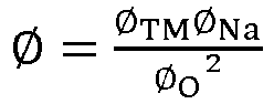 wherein
- The cathode active material according to claim 1, wherein in the chemical formula NaxNiaFebMncMaO2 of the cathode active material, the doping element M is selected from at least one of Li, K, Rb, Be, Mg, Ca, Cu, Sr, and Zn.
- The cathode active material according to claim 1, wherein in the chemical formula NaxNiaFebMncMaO2 of the cathode active material, 0.7≤x≤0.8, 0.01≤a≤0.4, 0.01≤b≤0.35, 0.3≤c,0.8, and 0≤d≤0.1.
- The cathode active material according to claim 1, wherein in an X-ray diffraction result of the layered oxide, a peak position of the diffraction peak (002) of the P2 phase is present at 2θ=15.80±0.5°, and a peak position of the diffraction peak (104) of the O3 phase is present at 2θ=41.5±0.5°.
- The cathode active material according to claim 1, wherein a particle size D50 of the cathode active material is 3-15 µm; and
a specific surface area of the cathode active material is 0.2-0.8 m2/g. - The cathode active material according to claim 1, wherein pH of the cathode active material is 11-13.
- The cathode active material according to claim 1, wherein a tap density of the cathode active material is 1.6 g/cm3.
- The cathode active material according to claim 1, wherein a mass content of CO3 2- in the cathode active material is ≤2 wt%, and a mass content of OH- in the cathode material is ≤ 2wt%; and
a mass content of water in the cathode active material is ≤0.05 wt%. - A cathode plate, comprising the cathode active material according to any one of claims 1-8.
- A sodium ion secondary battery, comprising the cathode plate according to claim 9.
Applications Claiming Priority (2)
| Application Number | Priority Date | Filing Date | Title |
|---|---|---|---|
| CN202311151572.5A CN116873988B (en) | 2023-09-07 | 2023-09-07 | Cathode active materials and preparation methods and applications thereof |
| PCT/CN2024/110617 WO2025050917A1 (en) | 2023-09-07 | 2024-08-08 | Positive electrode active material, and preparation method therefor and use thereof |
Publications (2)
| Publication Number | Publication Date |
|---|---|
| EP4545485A1 true EP4545485A1 (en) | 2025-04-30 |
| EP4545485A4 EP4545485A4 (en) | 2025-06-18 |
Family
ID=88268448
Family Applications (1)
| Application Number | Title | Priority Date | Filing Date |
|---|---|---|---|
| EP24772199.6A Pending EP4545485A4 (en) | 2023-09-07 | 2024-08-08 | POSITIVE ELECTRODE ACTIVE MATERIAL AND PRODUCTION METHOD THEREOF AND USE THEREOF |
Country Status (3)
| Country | Link |
|---|---|
| EP (1) | EP4545485A4 (en) |
| CN (1) | CN116873988B (en) |
| WO (1) | WO2025050917A1 (en) |
Families Citing this family (7)
| Publication number | Priority date | Publication date | Assignee | Title |
|---|---|---|---|---|
| CN116873988B (en) * | 2023-09-07 | 2023-12-29 | 深圳市贝特瑞新能源技术研究院有限公司 | Cathode active materials and preparation methods and applications thereof |
| CN118919709A (en) * | 2023-10-17 | 2024-11-08 | 湖南钠方新能源科技有限责任公司 | Positive electrode material, positive electrode plate, sodium ion battery and preparation method and application of positive electrode material and positive electrode plate |
| CN117577827B (en) * | 2024-01-16 | 2024-04-05 | 溧阳中科海钠科技有限责任公司 | Positive electrode material of sodium ion battery, preparation method and sodium ion secondary battery |
| KR102941454B1 (en) * | 2024-04-05 | 2026-03-18 | 포항공과대학교 산학협력단 | Cathode active material for sodium ion battery, and sodium ion battery comprising the same |
| CN118016864B (en) * | 2024-04-10 | 2024-07-09 | 深圳市贝特瑞新能源技术研究院有限公司 | Layered oxide positive electrode material and preparation method and application thereof |
| CN118507711B (en) * | 2024-04-15 | 2025-10-21 | 比亚迪股份有限公司 | Sodium-ion positive electrode material, preparation method thereof, and sodium-ion battery |
| CN119852389B (en) * | 2024-12-20 | 2025-08-08 | 天津中电新能源研究院有限公司 | Composite domain sodium-electricity positive electrode material, preparation method, positive electrode plate, battery and electricity utilization device |
Family Cites Families (8)
| Publication number | Priority date | Publication date | Assignee | Title |
|---|---|---|---|---|
| JP6083556B2 (en) * | 2012-10-24 | 2017-02-22 | 国立研究開発法人産業技術総合研究所 | Cathode active material for sodium ion secondary battery |
| CN104795551B (en) * | 2014-07-17 | 2017-07-14 | 中国科学院物理研究所 | A kind of layered copper oxide material and its production and use |
| CN109585795A (en) * | 2017-09-29 | 2019-04-05 | 中国科学院物理研究所 | Mixed phase structure layered oxide material and its preparation method and application |
| GB201805884D0 (en) * | 2018-04-09 | 2018-05-23 | Faradion Ltd | O3/P2 Mixed phase sodium-containing doped layered oxide materials |
| CN116802872A (en) * | 2021-12-29 | 2023-09-22 | 宁德时代新能源科技股份有限公司 | Layered oxide positive electrode active material, and positive electrode sheet, sodium ion battery and electrical device containing the same |
| CN116425212B (en) * | 2023-03-15 | 2025-07-25 | 北京航空航天大学 | High-entropy doped layered oxide, preparation method thereof, positive electrode material and sodium ion battery |
| CN116573683B (en) * | 2023-04-07 | 2024-12-27 | 北京航空航天大学 | Sodium-rich P2/O3 biphase layered oxide, preparation method thereof, sodium ion battery positive electrode material and battery |
| CN116873988B (en) * | 2023-09-07 | 2023-12-29 | 深圳市贝特瑞新能源技术研究院有限公司 | Cathode active materials and preparation methods and applications thereof |
-
2023
- 2023-09-07 CN CN202311151572.5A patent/CN116873988B/en active Active
-
2024
- 2024-08-08 EP EP24772199.6A patent/EP4545485A4/en active Pending
- 2024-08-08 WO PCT/CN2024/110617 patent/WO2025050917A1/en active Pending
Also Published As
| Publication number | Publication date |
|---|---|
| CN116873988A (en) | 2023-10-13 |
| WO2025050917A1 (en) | 2025-03-13 |
| CN116873988B (en) | 2023-12-29 |
| EP4545485A4 (en) | 2025-06-18 |
Similar Documents
| Publication | Publication Date | Title |
|---|---|---|
| EP4545485A1 (en) | Positive electrode active material, and preparation method therefor and use thereof | |
| Choi et al. | Recent progress and perspective of advanced high‐energy Co‐less Ni‐rich cathodes for Li‐ion batteries: yesterday, today, and tomorrow | |
| Pahari et al. | On controlling the P2-O2 phase transition by optimal Ti-substitution on Ni-site in P2-type Na0. 67Ni0. 33Mn0. 67O2 (NNMO) cathode for Na-ion batteries | |
| Peng et al. | Recent research on aqueous zinc-ion batteries and progress in optimizing full-cell performance | |
| Zheng et al. | Stabilizing NaCrO2 by sodium site doping with calcium | |
| Liu et al. | Comparison of structure and electrochemistry of Al-and Fe-doped LiNi1/3Co1/3Mn1/3O2 | |
| Choi et al. | Comparison of metal ion dissolutions from lithium ion battery cathodes | |
| Liu et al. | A comparative study of LiNi0. 8Co0. 2O2 cathode materials modified by lattice-doping and surface-coating | |
| Doeff et al. | A high-rate manganese oxide for rechargeable lithium battery applications | |
| Kim et al. | Effect of Ti Substitution for Mn on the Structure of LiNi0. 5Mn1. 5− x Ti x O 4 and Their Electrochemical Properties as Lithium Insertion Material | |
| CN103794773B (en) | A kind of method of producing high power capacity 523 type tertiary cathode material | |
| KR100430938B1 (en) | Cathode material for lithium secondary battery and mathod for manufacturing the same | |
| Nguyen et al. | Effect of calcination temperature on a P-type Na0. 6Mn0. 65Ni0. 25Co0. 10O2 cathode material for sodium-ion batteries | |
| CN117317213B (en) | Layered oxide positive electrode material and preparation method thereof, positive electrode sheet and sodium ion secondary battery | |
| Zhou et al. | Improving electrochemical performance of spinel-type Ni/Mn-based high-voltage cathode material for lithium-ion batteries via La-F co-doping combined with in-situ integrated perovskite LaMnO3 coating layer | |
| Saint et al. | Electrode materials with the Na0. 44MnO2 structure: effect of titanium substitution on physical and electrochemical properties | |
| Yuan et al. | Zinc doped P2-type layered cathode for high-voltage and long-life sodium ion batteries: impacts of calcination temperature and cooling methods | |
| Shao et al. | Performance of Na0. 44Mn1− x M x O2 (M= Ni, Mg; 0≤ x≤ 0.44) as a cathode for rechargeable sodium ion batteries | |
| Patoux et al. | Layered manganese oxide intergrowth electrodes for rechargeable lithium batteries. 2. Substitution with Al | |
| CN117239081A (en) | Sodium ion battery positive electrode material and preparation method thereof | |
| Pang et al. | Resolving the relationship between capacity/voltage decay and the phase transition by accelerating the layered to spinel transition | |
| Eriksson et al. | A study of layered lithium manganese oxide cathode materials | |
| Goharshadi et al. | Effects of Ba dopant on the structural, microstructural, and electrochemical properties of NCM811 cathode material (BaxLi1− xNi0. 8Co0. 1Mn0. 1O2) for Li-ion storage | |
| US8187750B2 (en) | Negative active material including lithium vanadium oxide for non-aqueous rechargeable battery, and non-aqueous rechargeable battery including same | |
| Xu et al. | Optimizing high-nickel and lithium-rich manganese-based oxide cathodes through microstructure manipulations for lithium-ion batteries |
Legal Events
| Date | Code | Title | Description |
|---|---|---|---|
| STAA | Information on the status of an ep patent application or granted ep patent |
Free format text: STATUS: UNKNOWN |
|
| STAA | Information on the status of an ep patent application or granted ep patent |
Free format text: STATUS: THE INTERNATIONAL PUBLICATION HAS BEEN MADE |
|
| PUAI | Public reference made under article 153(3) epc to a published international application that has entered the european phase |
Free format text: ORIGINAL CODE: 0009012 |
|
| STAA | Information on the status of an ep patent application or granted ep patent |
Free format text: STATUS: REQUEST FOR EXAMINATION WAS MADE |
|
| 17P | Request for examination filed |
Effective date: 20240924 |
|
| AK | Designated contracting states |
Kind code of ref document: A1 Designated state(s): AL AT BE BG CH CY CZ DE DK EE ES FI FR GB GR HR HU IE IS IT LI LT LU LV MC ME MK MT NL NO PL PT RO RS SE SI SK SM TR |
|
| REG | Reference to a national code |
Ref country code: DE Ref legal event code: R079 Free format text: PREVIOUS MAIN CLASS: C01G0053000000 Ipc: H01M0010054000 |
|
| A4 | Supplementary search report drawn up and despatched |
Effective date: 20250515 |
|
| RIC1 | Information provided on ipc code assigned before grant |
Ipc: H01M 4/131 20100101ALI20250509BHEP Ipc: H01M 4/62 20060101ALI20250509BHEP Ipc: H01M 4/505 20100101ALI20250509BHEP Ipc: H01M 4/525 20100101ALI20250509BHEP Ipc: C01G 53/51 20250101ALI20250509BHEP Ipc: C01G 53/50 20250101ALI20250509BHEP Ipc: H01M 10/054 20100101AFI20250509BHEP |