EP4545470A1 - Crane - Google Patents
Crane Download PDFInfo
- Publication number
- EP4545470A1 EP4545470A1 EP23827116.7A EP23827116A EP4545470A1 EP 4545470 A1 EP4545470 A1 EP 4545470A1 EP 23827116 A EP23827116 A EP 23827116A EP 4545470 A1 EP4545470 A1 EP 4545470A1
- Authority
- EP
- European Patent Office
- Prior art keywords
- cooling
- cooling device
- circuit
- crane
- traveling
- Prior art date
- Legal status (The legal status is an assumption and is not a legal conclusion. Google has not performed a legal analysis and makes no representation as to the accuracy of the status listed.)
- Pending
Links
Images



Classifications
-
- B—PERFORMING OPERATIONS; TRANSPORTING
- B66—HOISTING; LIFTING; HAULING
- B66C—CRANES; LOAD-ENGAGING ELEMENTS OR DEVICES FOR CRANES, CAPSTANS, WINCHES, OR TACKLES
- B66C13/00—Other constructional features or details
- B66C13/18—Control systems or devices
- B66C13/22—Control systems or devices for electric drives
-
- B—PERFORMING OPERATIONS; TRANSPORTING
- B66—HOISTING; LIFTING; HAULING
- B66C—CRANES; LOAD-ENGAGING ELEMENTS OR DEVICES FOR CRANES, CAPSTANS, WINCHES, OR TACKLES
- B66C13/00—Other constructional features or details
-
- B—PERFORMING OPERATIONS; TRANSPORTING
- B60—VEHICLES IN GENERAL
- B60K—ARRANGEMENT OR MOUNTING OF PROPULSION UNITS OR OF TRANSMISSIONS IN VEHICLES; ARRANGEMENT OR MOUNTING OF PLURAL DIVERSE PRIME-MOVERS IN VEHICLES; AUXILIARY DRIVES FOR VEHICLES; INSTRUMENTATION OR DASHBOARDS FOR VEHICLES; ARRANGEMENTS IN CONNECTION WITH COOLING, AIR INTAKE, GAS EXHAUST OR FUEL SUPPLY OF PROPULSION UNITS IN VEHICLES
- B60K1/00—Arrangement or mounting of electrical propulsion units
-
- B—PERFORMING OPERATIONS; TRANSPORTING
- B66—HOISTING; LIFTING; HAULING
- B66C—CRANES; LOAD-ENGAGING ELEMENTS OR DEVICES FOR CRANES, CAPSTANS, WINCHES, OR TACKLES
- B66C23/00—Cranes comprising essentially a beam, boom, or triangular structure acting as a cantilever and mounted for translatory of swinging movements in vertical or horizontal planes or a combination of such movements, e.g. jib-cranes, derricks, tower cranes
- B66C23/18—Cranes comprising essentially a beam, boom, or triangular structure acting as a cantilever and mounted for translatory of swinging movements in vertical or horizontal planes or a combination of such movements, e.g. jib-cranes, derricks, tower cranes specially adapted for use in particular purposes
- B66C23/36—Cranes comprising essentially a beam, boom, or triangular structure acting as a cantilever and mounted for translatory of swinging movements in vertical or horizontal planes or a combination of such movements, e.g. jib-cranes, derricks, tower cranes specially adapted for use in particular purposes mounted on road or rail vehicles; Manually-movable jib-cranes for use in workshops; Floating cranes
- B66C23/38—Cranes comprising essentially a beam, boom, or triangular structure acting as a cantilever and mounted for translatory of swinging movements in vertical or horizontal planes or a combination of such movements, e.g. jib-cranes, derricks, tower cranes specially adapted for use in particular purposes mounted on road or rail vehicles; Manually-movable jib-cranes for use in workshops; Floating cranes with separate prime movers for crane and vehicle
-
- B—PERFORMING OPERATIONS; TRANSPORTING
- B66—HOISTING; LIFTING; HAULING
- B66C—CRANES; LOAD-ENGAGING ELEMENTS OR DEVICES FOR CRANES, CAPSTANS, WINCHES, OR TACKLES
- B66C23/00—Cranes comprising essentially a beam, boom, or triangular structure acting as a cantilever and mounted for translatory of swinging movements in vertical or horizontal planes or a combination of such movements, e.g. jib-cranes, derricks, tower cranes
- B66C23/54—Cranes comprising essentially a beam, boom, or triangular structure acting as a cantilever and mounted for translatory of swinging movements in vertical or horizontal planes or a combination of such movements, e.g. jib-cranes, derricks, tower cranes with pneumatic or hydraulic motors, e.g. for actuating jib-cranes on tractors
-
- B—PERFORMING OPERATIONS; TRANSPORTING
- B60—VEHICLES IN GENERAL
- B60K—ARRANGEMENT OR MOUNTING OF PROPULSION UNITS OR OF TRANSMISSIONS IN VEHICLES; ARRANGEMENT OR MOUNTING OF PLURAL DIVERSE PRIME-MOVERS IN VEHICLES; AUXILIARY DRIVES FOR VEHICLES; INSTRUMENTATION OR DASHBOARDS FOR VEHICLES; ARRANGEMENTS IN CONNECTION WITH COOLING, AIR INTAKE, GAS EXHAUST OR FUEL SUPPLY OF PROPULSION UNITS IN VEHICLES
- B60K1/00—Arrangement or mounting of electrical propulsion units
- B60K2001/003—Arrangement or mounting of electrical propulsion units with means for cooling the electrical propulsion units
- B60K2001/006—Arrangement or mounting of electrical propulsion units with means for cooling the electrical propulsion units the electric motors
-
- B—PERFORMING OPERATIONS; TRANSPORTING
- B66—HOISTING; LIFTING; HAULING
- B66C—CRANES; LOAD-ENGAGING ELEMENTS OR DEVICES FOR CRANES, CAPSTANS, WINCHES, OR TACKLES
- B66C2700/00—Cranes
- B66C2700/03—Cranes with arms or jibs; Multiple cranes
- B66C2700/0321—Travelling cranes
- B66C2700/0357—Cranes on road or off-road vehicles, on trailers or towed vehicles; Cranes on wheels or crane-trucks
- B66C2700/0364—Cranes on road or off-road vehicles, on trailers or towed vehicles; Cranes on wheels or crane-trucks with a slewing arm
- B66C2700/0371—Cranes on road or off-road vehicles, on trailers or towed vehicles; Cranes on wheels or crane-trucks with a slewing arm on a turntable
-
- B—PERFORMING OPERATIONS; TRANSPORTING
- B66—HOISTING; LIFTING; HAULING
- B66C—CRANES; LOAD-ENGAGING ELEMENTS OR DEVICES FOR CRANES, CAPSTANS, WINCHES, OR TACKLES
- B66C2700/00—Cranes
- B66C2700/03—Cranes with arms or jibs; Multiple cranes
- B66C2700/0321—Travelling cranes
- B66C2700/0357—Cranes on road or off-road vehicles, on trailers or towed vehicles; Cranes on wheels or crane-trucks
- B66C2700/0378—Construction details related to the travelling, to the supporting of the crane or to the blocking of the axles; Outriggers; Coupling of the travelling mechamism to the crane mechanism
Definitions
- the present invention relates to a crane.
- Patent Literature 1 discloses a mobile crane including a lower traveling body having a traveling function and an upper turning body provided in a turnable state on an upper part of the lower traveling body.
- the lower traveling body includes an engine and travels based on the power of the engine.
- Patent Literature 1 JP 2012-96928 A
- An object of the present invention is to provide a crane that can travel by electric power.
- One aspect of a crane according to the present invention is a crane including:
- a crane according to the embodiment described below is an example of the crane according to the present invention, and the present invention is not limited to the embodiments described below.
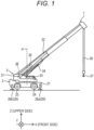
- Fig. 1 is a schematic view of a mobile crane 1 (in the illustrated case, rough terrain crane) according to the present embodiment.
- the mobile crane is, for example, an all-terrain crane, a truck crane, or a loading truck crane (also referred to as a cargo crane).
- the crane according to the present invention may be various cranes.
- the mobile crane 1 includes a lower traveling body 2 and an upper turning body 3.
- the mobile crane 1 is an electric crane including a high-voltage battery 70 (see Fig. 2 ).
- the mobile crane 1 travels on the basis of the electric power supplied from the high-voltage battery 70. That is, the mobile crane 1 does not include an engine.
- the mobile crane 1 executes an operation other than traveling (for example, crane operations, cooling, and/or heating) based on the electric power supplied from the high-voltage battery 70.
- the crane operation is, for example, a turning operation and/or a winch operation in a cargo conveyance operation.
- a specific configuration of the mobile crane 1 will be described.
- Fig. 1 is a schematic diagram of the mobile crane 1.
- the upper turning body 3 is provided on the upper part of the lower traveling body 2, and can turn about a turning center axis ⁇ with respect to the lower traveling body 2.
- the upper turning body 3 includes a turning base 31, a telescopic boom 32, and a cab 33.
- the turning base 31 is supported on the upper part of the lower traveling body 2 via a bearing (not illustrated).
- the turning base 31 turns based on the power generated by a turning actuator (not illustrated) provided in the upper turning body 3.
- the turning actuator is a hydraulic motor.
- the motor operates based on supply and discharge of hydraulic oil.
- the hydraulic oil is supplied from the lower traveling body 2.
- the turning actuator may be an electric motor. In this case, the electric motor for turning is driven on the basis of the electric power supplied from a high-voltage battery 70 described later.
- the telescopic boom 32 is supported by the turning base 31 and has a plurality of telescopically combined booms.
- the telescopic boom 32 can change the derricking angle based on the power generated by a derricking cylinder 34 (derricking).
- the derricking cylinder 34 is a telescopic hydraulic cylinder and is provided in the upper turning body 3.
- the derricking cylinder 34 operates based on supply and discharge of hydraulic oil.
- the hydraulic oil is supplied by a hydraulic oil supply device 8 (see Fig. 2 ) provided in the lower traveling body 2.
- the motor for winching may be an electric motor.
- the electric motor for winching is driven on the basis of the electric power supplied from the high-voltage battery 70 described later.
- the X direction coincides with the front-rear direction of the lower traveling body 2.
- the +side in the X direction coincides with the front side of the lower traveling body 2.
- the -side in the X direction coincides with the rear side of the lower traveling body 2.
- the Y direction coincides with the left-right direction of the lower traveling body 2.
- the +side in the Y direction corresponds to the left side when the front is viewed from the lower traveling body 2.
- the -side in the Y direction corresponds to the right side when the front is viewed from the lower traveling body 2.
- the Z direction coincides with the up-down direction of the lower traveling body 2.
- the +side in the Z direction coincides with the upper side of the lower traveling body 2.
- the -side in the Z direction corresponds to the lower side of the lower traveling body 2.
- the lower traveling body 2 corresponds to an example of a traveling vehicle body, and can travel by electric power. Specifically, as illustrated in Figs. 1 and 3 , the lower traveling body 2 includes a frame 20, a body 21, a front axle 22, a rear axle 23, front tires 24, rear tires 25, and an outrigger 26.
- the frame 20 is a box-shaped member extending in the front-rear direction and having a rectangular cross-sectional shape, for example, and constitutes a framework of the lower traveling body 2.
- the frame 20 includes an upper plate 20a, a lower plate 20b, a left plate 20c, a right plate 20d, a front plate 20e, and a rear plate 20f.
- the frame 20 has a slip ring arrangement space 200 formed by a through hole penetrating the frame 20 in the up-down direction.
- the slip ring arrangement space 200 is provided at a central position between the front axle 22 and the rear axle 23 in the frame 20.
- the frame 20 has a pair of front outrigger supports 202 at the front end.
- the frame 20 has a pair of rear outrigger supports 203 at the rear end.
- the body 21 (see Fig. 1 ) is a member constituting the outer shape of the lower traveling body 2, and is supported by the frame 20.
- the front axle 22 is a shaft member extending in the left-right direction, and is supported by a portion of the frame 20 near the front end of the lower plate 20b.
- the front tires 24 are rotatably supported at both ends of the front axle 22 in the left-right direction.
- the rear axle 23 is a shaft member extending in the left-right direction, and is supported by a portion of the frame 20 near the rear end of the lower plate 20b.
- the rear tires 25 are rotatably supported at both ends of the rear axle 23 in the left-right direction.
- the mobile crane 1 is a so-called biaxial mobile crane including the front axle 22 and the rear axle 23.
- the mobile crane may be a so-called multiaxial mobile crane having three or more axles.
- the outrigger 26 includes a pair of front outriggers 26a and a pair of rear outriggers 26b. Each of the pair of front outriggers 26a is supported by the pair of front outrigger supports 202 of the frame 20. Further, each of the pair of rear outriggers 26b is supported by the pair of rear outrigger supports 203 of the frame 20.
- the mobile crane 1 includes a transmission member 4 provided between the lower traveling body 2 and the upper turning body 3. Specifically, the transmission member 4 is disposed in the slip ring arrangement space 200 of the frame 20. Such a transmission member 4 is a member for transmitting electric power, fluid (hydraulic oil and/or compressed air), signals, and the like between the lower traveling body 2 and the upper turning body 3 which rotate relatively.
- a transmission member 4 is a member for transmitting electric power, fluid (hydraulic oil and/or compressed air), signals, and the like between the lower traveling body 2 and the upper turning body 3 which rotate relatively.
- the mobile crane 1 includes a hydraulic system 5, a low-voltage system 6, and a high-voltage system 7.
- a hydraulic system 5 As illustrated in Fig. 2 , the mobile crane 1 includes a hydraulic system 5, a low-voltage system 6, and a high-voltage system 7.
- configurations of the hydraulic system 5, the low-voltage system 6, and the high-voltage system 7 will be described.
- the hydraulic system 5 includes a tank 51, a hydraulic oil supply device 8, a transmission member 4, and a hydraulic device 53.
- the elements constituting the hydraulic system 5 are connected by a circuit indicated by a thick line in Fig. 2 .
- the tank 51 and the hydraulic oil supply device 8 are provided in the lower traveling body 2.
- the hydraulic oil supply device 8 includes an electric motor 80, a speed reducer 81, and a pump 82.
- the electric motor 80 is driven on the basis of the electric power supplied from a high-voltage battery 70 described later via a lower junction box 71 and an inverter 83.
- the rotation of the electric motor 80 is transmitted to the pump 82 via the speed reducer 81.
- the pump 82 operates based on the rotation transmitted from the electric motor 80.
- the hydraulic oil supply device 8 supplies the hydraulic oil stored in the tank 51 to the transmission member 4 via the oil passage.
- the transmission member 4 constitutes a flow path of fluid (for example, hydraulic oil and/or compressed air) supplied from the lower traveling body 2 to the upper turning body 3 between the lower traveling body 2 and the upper turning body 3 which rotate relatively.
- the transmission member 4 has a function of transmitting the hydraulic oil supplied from the hydraulic oil supply device 8 to the hydraulic device 53 provided in the upper turning body 3.
- the hydraulic device 53 includes a turning actuator (not illustrated), a derricking cylinder 34, a telescopic cylinder 35, and a winch actuator (not illustrated).
- the hydraulic oil used in the hydraulic device 53 passes through the transmission member 4 and returns to the tank 51.
- the low-voltage system 6 includes a lower controller 60, a transmission member 4, an upper controller 61, a DC-DC converter 64, an electric fan 910, first pumps 90a and 90b, and a low-voltage battery 63.
- the elements constituting the low-voltage system 6 are connected by a circuit indicated by a dotted line in Fig. 2 .
- the lower controller 60 transmits, for example, a video signal, a detection signal of a sensor, and a control signal to the upper controller 61 via the transmission member 4.
- the control signal is a signal for controlling the operation of a device (for example, the hydraulic device 53 and the upper electric device 74) provided in the upper turning body 3 to be controlled.
- the signals including these signals and transmitted from the lower controller 60 to the upper controller 61 are collectively referred to as lower generation signals.
- the lower controller 60 operates based on the electric power supplied from the low-voltage battery 63.
- the lower controller 60 may be a controller for operating a lower electric device provided in the lower traveling body 2.
- the lower electric device includes, for example, a DC-DC converter 64, an electric fan 910, a cooling pump 65, and the like.
- a circuit connecting the lower controller 60 and devices other than the transmission member 4 and the low-voltage battery 63 is omitted.
- the upper controller 61 transmits the lower generation signal received from the lower controller 60 to a control device that controls the operation of the device provided in the upper turning body 3.
- the control device is, for example, an electromagnetic valve that controls the operation of the hydraulic device 53 or a controller that controls the operation of the upper electric device 74.
- the low-voltage system 6 may transmit, for example, information on the operation of a device provided in the upper turning body 3 and/or a current equal to or lower than a predetermined voltage supplied to the device from the lower traveling body 2 to the upper turning body 3.
- the DC-DC converter 64 is connected to the high-voltage battery 70 via the lower junction box 71.
- the DC-DC converter 64 steps down the voltage of the high-voltage battery 70 and supplies the voltage to the low-voltage battery 63.
- the electric fan 910 constitutes a lower cooling system 9 described later.
- the electric fan 910 operates based on the electric power supplied from the low-voltage battery 63.
- the pumps 90a and 90b constitute the lower cooling system 9 described later.
- the pumps 90a and 90b operate based on the electric power supplied from the low-voltage battery 63.
- the high-voltage system 7 is a system for executing traveling of the lower traveling body 2 and operations other than traveling (for example, crane operations, cooling, and/or heating) based on the electric power supplied from the high-voltage battery 70.
- operations other than traveling for example, crane operations, cooling, and/or heating
- the configuration of the high-voltage system 7 will be described.
- the high-voltage system 7 includes, as main elements, a high-voltage battery 70, a lower junction box 71, a traveling inverter 72, a traveling motor 73, an electric air compressor 75, an on-board charger 76, a transmission member 4, and an upper electric device 74.
- the elements constituting the high-voltage system 7 are connected by a circuit indicated by a thin solid line in Fig. 2 .
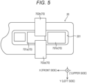
- the high-voltage battery 70 corresponds to an example of a power supply unit, and includes a plurality of batteries 701a, 701b, 702a, and 702b as illustrated in Fig. 5 .
- the batteries 701a and 701b are disposed in the battery housing space 201 of the frame 20.
- the high-voltage battery 70 can be compactly arranged, and damage due to impact or the like of the high-voltage battery 70 can be suppressed.
- the batteries 702a and 702b are disposed outside the frame 20 and above the batteries 701a and 701b.
- the lower junction box 71 is provided in the lower traveling body 2, and is for distributing the electric power supplied from the high-voltage battery 70.
- the lower junction box 71 is connected to the high-voltage battery 70 and the traveling inverter 72.
- the traveling inverter 72 is provided in the lower traveling body 2 and is connected to the traveling motor 73.
- the traveling inverter 72 adjusts the current received from the lower junction box 71 and sends the adjusted current to the traveling motor 73.
- the traveling inverter 72 and the traveling motor 73 constitute a traveling drive device 77.
- the traveling motor 73 includes a front traveling motor 730 and a rear traveling motor 731.
- the front traveling motor 730 and the rear traveling motor 731 are provided below the frame 20 and between the front axle 22 and the rear axle 23.
- An output shaft of the front traveling motor 730 is connected to a front driving shaft 27a.
- the front end of the front driving shaft 27a is connected to the front axle 22 via a gear (for example, a speed reducer).
- An output shaft of the rear traveling motor 731 is connected to the rear driving shaft 27b.
- the rear end of the rear driving shaft 27b is connected to the rear axle 23 via a gear (for example, a speed reducer).
- the electric air compressor 75 constitutes a brake system (not illustrated). Such an electric air compressor 75 is driven on the basis of the electric power supplied from the high-voltage battery 70 under the control of a control unit (not illustrated).
- the on-board charger 76 constitutes a charging system (not illustrated) for charging the high-voltage battery 70.
- the electric motor for turning is driven based on the electric power.
- the electric motor for turning turns the upper turning body 3.
- the electric motor for winching is driven on the basis of the electric power.
- the electric motor for winching rotates the winch (not illustrated).
- the wire rope 36 is wound up or unwound, and the hook 37 ascends or descends.
- the mobile crane 1 of the present embodiment includes a lower cooling system 9 for cooling various devices provided in the lower traveling body 2.
- a lower cooling system 9 for cooling various devices provided in the lower traveling body 2.
- the lower cooling system 9 includes a first cooling system 9a and a second cooling system 9b.
- the first cooling system 9a is a system for cooling a lower electric device mounted on the lower traveling body 2.
- the lower electric device cooled by the first cooling system 9a includes the traveling inverter 72, the front traveling motor 730, the rear traveling motor 731, the electric air compressor 75, and the on-board charger 76 constituting the high-voltage system 7.
- the lower electric device cooled by the first cooling system 9a includes, for example, an electric motor 80 and an inverter 83 constituting the hydraulic oil supply device 8.
- the lower electric device cooled by the first cooling system 9a includes, for example, a DC-DC converter 64 constituting the low-voltage system 6.
- the first cooling system 9a includes a first pump 90a, a second pump 90b, and a cooling device 91.
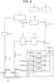
- Each of the first pump 90a and the second pump 90b is provided in the lower traveling body 2. As illustrated in Fig. 6 , the first pump 90a and the second pump 90b are connected in parallel in the first cooling system 9a.
- the cooling circuit through which the cooling liquid discharged from the first pump 90a circulates is referred to as a traveling system cooling circuit (first cooling circuit).
- a cooling circuit through which the cooling liquid discharged from the second pump 90b circulates is referred to as a work system cooling circuit (second cooling circuit). That is, the traveling system cooling circuit and the work system cooling circuit are provided in parallel in the first cooling system 9a.
- the capacities of the first pump 90a and the second pump 90b and the cooling targets (devices) allocated to the traveling system cooling circuit and the work system cooling circuit are determined according to the upper limit of the flow rate of the cooling circuit corresponding to each device, the resistance (pipeline resistance) in the cooling circuit corresponding to each device, the temperature of the cooling liquid necessary for cooling each device, and the like.
- the cooling liquid circulates constantly in the traveling system cooling circuit and the work system cooling circuit.
- a cooling circuit for circulating a cooling liquid may be switched according to the state of the mobile crane 1. Specifically, when the mobile crane 1 travels, the cooling liquid may be circulated in the traveling system cooling circuit, and the cooling liquid may not be circulated in the work system cooling circuit. Further, at the time of working of the mobile crane 1, the cooling liquid may be circulated in the traveling system cooling circuit while being circulated in the work system cooling circuit.
- the first pump 90a is an electric pump that is driven based on electric power supplied from the low-voltage battery 63, and sends the cooling liquid (for example, coolant) supplied from a cooling device 91 described later to a drive device cooling circuit (not illustrated) for cooling the traveling drive device 77.
- the cooling liquid flowing into the first pump 90a is cooled by the cooling device 91.
- the drive device cooling circuit is a cooling circuit for cooling the traveling inverter 72, the front traveling motor 730, and the rear traveling motor 731 constituting the traveling drive device 77.
- the cooling liquid discharged from the cooling device 91 flows as indicated by arrow A 11 in Fig. 6 and flows into the first pump 90a.
- the cooling liquid flowing out of the first pump 90a flows as indicated by arrow A 12 and flows into a drive device cooling circuit (not illustrated).
- the cooling liquid cools the traveling inverter 72, the front traveling motor 730, and the rear traveling motor 731 constituting the traveling drive device 77.
- the cooling liquid flowing out of the drive device cooling circuit flows into a charging system cooling circuit (not illustrated) for cooling the on-board charger 76.
- the cooling liquid cools the on-board charger 76 when flowing through the charging system cooling circuit.
- the cooling liquid flowing out of the charging system cooling circuit flows as indicated by arrow A 13 in Fig. 6 and flows into the cooling device 91.
- the second pump 90b is an electric pump that is driven based on electric power supplied from the low-voltage battery 63, and sends a cooling liquid (for example, coolant) supplied from the cooling device 91 described later to a braking system cooling circuit (not illustrated) for cooling the electric air compressor 75 and a supply device cooling circuit (not illustrated) for cooling the hydraulic oil supply device 8.
- the supply device cooling circuit is a cooling circuit for cooling the electric motor 80 and the inverter 83 constituting the hydraulic oil supply device 8.
- the cooling liquid flowing out of the cooling device 91 flows as indicated by arrow A 21 in Fig. 6 and flows into the second pump 90b.
- the cooling liquid flowing out of the second pump 90b flows as indicated by arrow A 22 in Fig. 6 , and flows into the braking system cooling circuit for cooling the electric air compressor 75.
- the cooling liquid flowing out of the braking system cooling circuit flows into the supply device cooling circuit (not illustrated) for cooling the hydraulic oil supply device 8.
- the cooling liquid cools the electric motor 80 and the inverter 83 when flowing through the supply device cooling circuit.
- the cooling liquid flowing out of the supply device cooling circuit flows as indicated by arrow A 23 in Fig. 6 , and flows into a low-voltage system cooling circuit (not illustrated) for cooling the DC-DC converter 64 constituting the low-voltage system 6.
- the cooling liquid cools the DC-DC converter 64 when flowing through the low-voltage system cooling circuit.
- the cooling liquid flowing out of the low-voltage system cooling circuit flows as indicated by arrow A 24 in Fig. 6 and flows into the cooling device 91.
- the cooling device 91 is a device for cooling a cooling liquid flowing through the first cooling system 9a.
- the cooling device 91 includes a plurality of cooling devices. Specifically, the cooling device 91 includes a first cooling device 91a, a second cooling device 91b, a third cooling device 91c, and a fourth cooling device 91d.
- the first cooling device 91a, the second cooling device 91b, the third cooling device 91c, and the fourth cooling device 91d are dispersedly arranged in the lower traveling body 2 and connected in parallel to each other.
- Each of the first cooling device 91a, the second cooling device 91b, the third cooling device 91c, and the fourth cooling device 91d cools the cooling liquid flowing through the first cooling system 9a. Note that the number of cooling devices is not limited to the illustrated case.
- the circuits connected to the inlet-side ports of the first cooling device 91a, the second cooling device 91b, the third cooling device 91c, and the fourth cooling device 91d are branched on the upstream side of the first cooling device 91a, the second cooling device 91b, the third cooling device 91c, and the fourth cooling device 91d to form a plurality of circuits (in the present embodiment, four circuits).
- the circuits connected to the outlet-side ports of the first cooling device 91a, the second cooling device 91b, the third cooling device 91c, and the fourth cooling device 91d are merged on the downstream side of the first cooling device 91a, the second cooling device 91b, the third cooling device 91c, and the fourth cooling device 91d to form one circuit.
- the cooling liquid flowing through the first cooling system 9a branches on the upstream side of the first cooling device 91a, the second cooling device 91b, the third cooling device 91c, and the fourth cooling device 91d, flows into the first cooling device 91a, the second cooling device 91b, the third cooling device 91c, and the fourth cooling device 91d, is cooled, and then joins to circulate in the first cooling system 9a.
- Each of the first cooling device 91a, the second cooling device 91b, the third cooling device 91c, and the fourth cooling device 91d includes an electric fan 910 and a radiator 911.
- the electric fan 910 is disposed so as to overlap the upper side of the radiator 911.
- the electric fan 910 operates based on the electric power supplied from the low-voltage battery 63.
- the first cooling device 91a, the second cooling device 91b, the third cooling device 91c, and the fourth cooling device 91d are dispersedly arranged above the rear end of the frame 20 so as to sandwich the battery housing space 201 of the frame 20.
- the first cooling device 91a and the second cooling device 91b correspond to an example of a left-side cooling device, and are disposed on the left side of the battery housing space 201 at the rear end of the frame 20.
- the first cooling device 91a and the second cooling device 91b are arranged side by side in the front-rear direction.
- the first cooling device 91a is disposed in front of the second cooling device 91b.
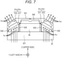
- the first cooling device 91a and the second cooling device 91b are disposed to face obliquely upward. Specifically, as illustrated in Fig. 7 , the first cooling device 91a and the second cooling device 91b are disposed with their upper surfaces facing obliquely upward to the left. In other words, the first cooling device 91a and the second cooling device 91b are disposed such that an end (right end) on a side close to a top tank 940 described later is higher than an end (left end) on a side far from the top tank 940. In Fig. 7 , the first cooling device 91a and the second cooling device 91b are collectively illustrated for convenience. The inclination angles of the first cooling device 91a and the second cooling device 91b with respect to the up-down direction are not limited to the inclination angles illustrated in Fig. 7 .
- the third cooling device 91c and the fourth cooling device 91d correspond to an example of a right-side cooling device, and are arranged side by side in the front-rear direction on the right side of the battery housing space 201 at the rear end of the frame 20.
- the third cooling device 91c is disposed in front of the fourth cooling device 91d.
- the first cooling device 91a and the third cooling device 91c are arranged side by side on the left and right with the battery housing space 201 interposed therebetween.
- the second cooling device 91b and the fourth cooling device 91d are arranged side by side on the left and right with the battery housing space 201 interposed therebetween.
- the third cooling device 91c and the fourth cooling device 91d are disposed to face obliquely upward. Specifically, as illustrated in Fig. 7 , the third cooling device 91c and the fourth cooling device 91d are disposed with their upper surfaces facing obliquely upward to the right. In other words, the third cooling device 91c and the fourth cooling device 91d are disposed such that an end (right end) on a side close to the top tank 940 described later is higher than an end (left end) on a side far from the top tank 940. In Fig. 7 , the third cooling device 91c and the fourth cooling device 91d are collectively illustrated for convenience. The inclination angles of the third cooling device 91c and the fourth cooling device 91d with respect to the up-down direction are not limited to the inclination angles illustrated in Fig. 7 .
- Each of the first cooling device 91a, the second cooling device 91b, the third cooling device 91c, and the fourth cooling device 91d is fixed to the upper surface of the rear end of the frame 20 via a mount member 930.
- the first cooling device 91a, the second cooling device 91b, the third cooling device 91c, and the fourth cooling device 91d are each covered with a cover 931.
- the cover 931 also covers the top tank 940 and the second cooling system 9b described later.
- the left end of the upper surface of the cover 931 is along the upper surfaces of the first cooling device 91a and the second cooling device 91b, and is inclined so as to face obliquely upward to the left.
- the right end of the upper surface of the cover 931 is along the upper surfaces of the third cooling device 91c and the fourth cooling device 91d, and is inclined so as to face obliquely upward to the right. Since the right end and the left end of the upper surface of the cover 931 are inclined surfaces as described above, a wide field of view of the worker in the cab 33 in a state where the upper turning body 3 has turned backward is secured.
- the first cooling system 9a includes the top tank 940.
- the top tank 940 corresponds to an example of an air vent tank, and is connected to the first cooling device 91a, the second cooling device 91b, the third cooling device 91c, and the fourth cooling device 91d.
- the top tank 940 is disposed above the second cooling system 9b described later and between the first cooling device 91a and the second cooling device 91b and the third cooling device 91c and the fourth cooling device 91d.
- the top tank 940 is disposed so as to be stretched between the cooling devices (the first cooling device 91a and the second cooling device 91b) disposed on the left side and the cooling devices (the third cooling device 91c and the fourth cooling device 91d) disposed on the right side.
- the cooling devices the first cooling device 91a and the second cooling device 91b
- the cooling devices the third cooling device 91c and the fourth cooling device 91d
- the expanded cooling liquid flows into the top tank 940. In this manner, an increase in the pressure of the first cooling system 9a based on the expansion of the cooling liquid is suppressed.
- the top tank 940 is disposed at a position higher than other devices (for example, the first cooling device 91a, the second cooling device 91b, the third cooling device 91c, and the fourth cooling device 91d) constituting the first cooling system 9a. Therefore, the air in the first cooling system 9a can be released to the top tank 940. As a result, it is possible to suppress failure of the first cooling system 9a caused by air in the first cooling system 9a.
- each of the first cooling device 91a, the second cooling device 91b, the third cooling device 91c, and the fourth cooling device 91d is disposed in an inclined state such that the end on a side close to the top tank 940 is higher than the end on a side far from the top tank 940. Therefore, the air in the first cooling device 91a, the second cooling device 91b, the third cooling device 91c, and the fourth cooling device 91d can be effectively released to the top tank 940. As a result, the failure of the first cooling system 9a can be more effectively suppressed.
- the cooling liquid having flowed into the first cooling device 91a, the second cooling device 91b, the third cooling device 91c, and the fourth cooling device 91d flows in the radiator 911 of each of the first cooling device 91a, the second cooling device 91b, the third cooling device 91c, and the fourth cooling device 91d.
- the electric fan 910 When the electric fan 910 is operated, air passes through the radiator 911 from the lower side to the upper side. At this time, the air passing through the radiator 911 cools the cooling liquid flowing in the radiator 911.
- the first cooling device 91a and the second cooling device 91b each suck up air below the frame 20 as indicated by arrow A a1 in Fig. 7 .
- the air sucked up by the first cooling device 91a and the second cooling device 91b cools the cooling liquid flowing through the radiator 911 of the first cooling device 91a and the second cooling device 91b (that is, after heat exchange), and then is discharged from the first cooling device 91a and the second cooling device 91b as indicated by arrow A a2 in Fig. 7 .
- the third cooling device 91c and the fourth cooling device 91d each suck up the air below the frame 20 as indicated by arrow A b1 in Fig. 7 .
- the air sucked up by the third cooling device 91c and the fourth cooling device 91d cools the cooling liquid flowing through the radiator 911 of the third cooling device 91c and the fourth cooling device 91d (that is, after heat exchange), and then is discharged from the third cooling device 91c and the fourth cooling device 91d as indicated by arrow A b2 in Fig. 7 .
- the first cooling device 91a, the second cooling device 91b, the third cooling device 91c, and the fourth cooling device 91d discharge the air sucked up from below the frame 20 to above the frame 20. Therefore, the noise level below the electric fan 910 of each of the first cooling device 91a, the second cooling device 91b, the third cooling device 91c, and the fourth cooling device 91d can be reduced.
- the second cooling system 9b is a system for cooling the first batteries 701a and 701b and the second batteries 702a and 702b constituting the high-voltage battery 70 mounted on the lower traveling body 2. As illustrated in Fig. 6 , the second cooling system 9b is a cooling system independent of the first cooling system 9a.
- the second cooling system 9b is disposed between the cooling devices (the first cooling device 91a and the second cooling device 91b) disposed above the battery housing space 201 and on the left side in the left-right direction and the cooling devices (the third cooling device 91c and the fourth cooling device 91d) disposed on the right side.
- the second cooling system 9b is disposed behind the second batteries 702a and 702b at the rear end of frame 20.
- Such a second cooling system 9b has a function of maintaining the temperature of the high-voltage battery 70 at a set temperature. A specific structure of the second cooling system 9b will not be described.
- FIG. 8 is a schematic diagram illustrating a modification of the cooling device.
- a cooling device 91A illustrated in Fig. 8 constitutes a first cooling system 9c, and includes a plurality of cooling devices dispersedly arranged side by side in the left-right direction at the rear end of the frame 20.
- the cooling device 91A includes a first cooling device 91e, a second cooling device 91f, a third cooling device 91g, and a fourth cooling device 91h in this order from the left side. Note that the number of cooling devices is not limited to the illustrated case.
- the structures of the first cooling device 91e, the second cooling device 91f, the third cooling device 91g, and the fourth cooling device 91h are similar to the structures of the first cooling device 91a, the second cooling device 91b, the third cooling device 91c, and the fourth cooling device 91d of the cooling device 91 described above. Therefore, regarding the structures of the first cooling device 91e, the second cooling device 91f, the third cooling device 91g, and the fourth cooling device 91h, the description regarding the first cooling device 91a, the second cooling device 91b, the third cooling device 91c, and the fourth cooling device 91d may be appropriately incorporated.
- Effects and advantages obtained from the configurations of the first cooling device 91e, the second cooling device 91f, the third cooling device 91g, and the fourth cooling device 91h are substantially similar to the operations and effects obtained from the configurations of the first cooling device 91a, the second cooling device 91b, the third cooling device 91c, and the fourth cooling device 91d.
- the first cooling device 91e and the second cooling device 91f correspond to the first cooling device 91a and the second cooling device 91b.
- the third cooling device 91g and the fourth cooling device 91h correspond to the third cooling device 91c and the fourth cooling device 91d.
- the first cooling device 91e, the second cooling device 91f, the third cooling device 91g, and the fourth cooling device 91h each are disposed to face obliquely upward. Specifically, the first cooling device 91e, the second cooling device 91f, the third cooling device 91g, and the fourth cooling device 91h each are disposed with the upper surfaces facing obliquely backward and upward. The first cooling device 91e, the second cooling device 91f, the third cooling device 91g, and the fourth cooling device 91h are disposed such that an end close to the top tank (not illustrated) is higher than an end far from the top tank.
- the directions in which the upper surfaces of the first cooling device 91e, the second cooling device 91f, the third cooling device 91g, and the fourth cooling device 91h face are not limited to the above-described directions.
- the first cooling device 91e and the second cooling device 91f may be disposed in a state where the upper surfaces thereof face obliquely upward to the rear left.
- the third cooling device 91g and the fourth cooling device 91h may be disposed in a state where the upper surfaces face obliquely upward to the rear right.
- the cooling device 91A of such a modification is adopted, the above-described second cooling system 9b may be omitted.
- the first cooling system 9c cools the high-voltage battery 70.
- the first cooling device 91e may be disposed in a state where the upper surface faces obliquely upward to the rear left.
- the fourth cooling device 91h may be disposed in a state where the upper surface faces obliquely upward to the rear right.
- the second cooling device 91f and the third cooling device 91g may be disposed in a state where the upper surfaces face obliquely rearward and upward.
- the first cooling device 91e, the second cooling device 91f, the third cooling device 91g, and the fourth cooling device 91h each may be covered with a cover (not illustrated).
- a cover may have a shape along the upper surfaces of the first cooling device 91e, the second cooling device 91f, the third cooling device 91g, and the fourth cooling device 91h.
- the present embodiment having the above configuration, it is possible to realize the mobile crane 1 capable of traveling based on the electric power of the high-voltage battery 70.
- the first cooling device 91a, the second cooling device 91b, the third cooling device 91c, and the fourth cooling device 91d are dispersedly arranged while being obliquely arranged, it is possible to achieve both securing of cooling performance and space saving at a high level.
- effects and advantages exhibited by the mobile crane 1 according to the present embodiment are as described above.
- the crane according to the present invention is not limited to a rough terrain crane and may be various mobile cranes such as an all-terrain crane, a truck crane, and a loading truck crane (also referred to as a cargo crane).
Landscapes
- Engineering & Computer Science (AREA)
- Mechanical Engineering (AREA)
- Chemical & Material Sciences (AREA)
- Combustion & Propulsion (AREA)
- Transportation (AREA)
- Automation & Control Theory (AREA)
- Arrangement Or Mounting Of Propulsion Units For Vehicles (AREA)
- Control And Safety Of Cranes (AREA)
- Jib Cranes (AREA)
Abstract
Description
- The present invention relates to a crane.
-
Patent Literature 1 discloses a mobile crane including a lower traveling body having a traveling function and an upper turning body provided in a turnable state on an upper part of the lower traveling body. The lower traveling body includes an engine and travels based on the power of the engine. - Patent Literature 1:
JP 2012-96928 A - In recent years, there has been a demand for motorized cranes as described above from the viewpoint of environmental protection and the like.
- An object of the present invention is to provide a crane that can travel by electric power.
- One aspect of a crane according to the present invention is a crane including:
- a traveling vehicle body that travels with a motor driven by a power supply unit; and
- a first cooling system that cools a lower electric device, in which
- the first cooling system includes a plurality of cooling devices dispersedly arranged on the traveling vehicle body, connected in parallel to each other, and configured to cool a fluid flowing through a circuit of the first cooling system.
- According to the present invention, it is possible to provide a crane that can travel by electric power.
-
-
Fig. 1 is a schematic view of a mobile crane according to an embodiment. -
Fig. 2 is a block diagram schematically illustrating a system configuration of a mobile crane. -
Fig. 3 is a perspective view of a crane from which a part of the configuration is omitted. -
Fig. 4 is a schematic cross-sectional view illustrating a state in which the periphery of the motor is viewed from the left side. -
Fig. 5 is a schematic diagram illustrating a battery periphery as viewed from above. -
Fig. 6 is a diagram illustrating a configuration of a lower cooling system. -
Fig. 7 is a schematic view illustrating a state in which the cooling device is viewed from behind. -
Fig. 8 is a schematic view illustrating a modification of the cooling device. - Hereinafter, an example of embodiments of a crane according to the present invention will be described in detail based on the drawings. Note that a crane according to the embodiment described below is an example of the crane according to the present invention, and the present invention is not limited to the embodiments described below.
-
Fig. 1 is a schematic view of a mobile crane 1 (in the illustrated case, rough terrain crane) according to the present embodiment. The mobile crane is, for example, an all-terrain crane, a truck crane, or a loading truck crane (also referred to as a cargo crane). However, the crane according to the present invention may be various cranes. - The
mobile crane 1 includes a lowertraveling body 2 and an upper turningbody 3. Themobile crane 1 is an electric crane including a high-voltage battery 70 (seeFig. 2 ). Themobile crane 1 travels on the basis of the electric power supplied from the high-voltage battery 70. That is, themobile crane 1 does not include an engine. - In addition, the
mobile crane 1 executes an operation other than traveling (for example, crane operations, cooling, and/or heating) based on the electric power supplied from the high-voltage battery 70. The crane operation is, for example, a turning operation and/or a winch operation in a cargo conveyance operation. Hereinafter, a specific configuration of themobile crane 1 will be described. - First, the configuration of the upper turning
body 3 will be described with reference toFig. 1. Fig. 1 is a schematic diagram of themobile crane 1. The upper turningbody 3 is provided on the upper part of the lower travelingbody 2, and can turn about a turning center axis α with respect to the lower travelingbody 2. The upper turningbody 3 includes aturning base 31, atelescopic boom 32, and acab 33. - The
turning base 31 is supported on the upper part of the lower travelingbody 2 via a bearing (not illustrated). Theturning base 31 turns based on the power generated by a turning actuator (not illustrated) provided in the upper turningbody 3. In the present embodiment, the turning actuator is a hydraulic motor. The motor operates based on supply and discharge of hydraulic oil. The hydraulic oil is supplied from the lower travelingbody 2. The turning actuator may be an electric motor. In this case, the electric motor for turning is driven on the basis of the electric power supplied from a high-voltage battery 70 described later. - The
telescopic boom 32 is supported by theturning base 31 and has a plurality of telescopically combined booms. Thetelescopic boom 32 can change the derricking angle based on the power generated by a derricking cylinder 34 (derricking). - The derricking
cylinder 34 is a telescopic hydraulic cylinder and is provided in the upper turningbody 3. The derrickingcylinder 34 operates based on supply and discharge of hydraulic oil. The hydraulic oil is supplied by a hydraulic oil supply device 8 (seeFig. 2 ) provided in thelower traveling body 2. - The
telescopic boom 32 expands and contracts based on the power generated by atelescopic cylinder 35. Thetelescopic cylinder 35 is a hydraulic cylinder and is provided inside thetelescopic boom 32. Thetelescopic cylinder 35 operates based on supply and discharge of hydraulic oil. Further, the hydraulic oil is supplied by the hydraulicoil supply device 8 provided in the lower travelingbody 2. - The
telescopic boom 32 supports awire rope 36. Thewire rope 36 hangs down from a distal end of thetelescopic boom 32, and ahook 37 is provided at the distal end. A part of thewire rope 36 is wound around a winch 38. - The winch 38 is driven (rotates) based on the power generated by a winch actuator (not illustrated). In the present embodiment, the winch actuator is provided on the
turning base 31 and is a hydraulic motor. The motor operates based on supply and discharge of hydraulic oil. The hydraulic oil is supplied by the hydraulicoil supply device 8 provided in thelower traveling body 2. - When the winch 38 rotates, the
wire rope 36 is wound up or unwound according to the rotation direction of the winch 38. The motor for winching may be an electric motor. In this case, the electric motor for winching is driven on the basis of the electric power supplied from the high-voltage battery 70 described later. - Next, the
lower traveling body 2 will be described with reference toFigs. 1 to 7 . In describing the structure of thelower traveling body 2, an orthogonal coordinate system (X, Y, Z) illustrated in each drawing is used. The X direction coincides with the front-rear direction of thelower traveling body 2. The +side in the X direction coincides with the front side of thelower traveling body 2. The -side in the X direction coincides with the rear side of thelower traveling body 2. The Y direction coincides with the left-right direction of thelower traveling body 2. The +side in the Y direction corresponds to the left side when the front is viewed from thelower traveling body 2. The -side in the Y direction corresponds to the right side when the front is viewed from thelower traveling body 2. The Z direction coincides with the up-down direction of thelower traveling body 2. The +side in the Z direction coincides with the upper side of thelower traveling body 2. The -side in the Z direction corresponds to the lower side of thelower traveling body 2. - The
lower traveling body 2 corresponds to an example of a traveling vehicle body, and can travel by electric power. Specifically, as illustrated inFigs. 1 and3 , thelower traveling body 2 includes aframe 20, abody 21, afront axle 22, arear axle 23,front tires 24,rear tires 25, and anoutrigger 26. - The
frame 20 is a box-shaped member extending in the front-rear direction and having a rectangular cross-sectional shape, for example, and constitutes a framework of thelower traveling body 2. Theframe 20 includes anupper plate 20a, alower plate 20b, aleft plate 20c, aright plate 20d, afront plate 20e, and arear plate 20f. - The
frame 20 has a slipring arrangement space 200 formed by a through hole penetrating theframe 20 in the up-down direction. The slipring arrangement space 200 is provided at a central position between thefront axle 22 and therear axle 23 in theframe 20. - The
frame 20 has abattery housing space 201 formed by a through hole penetrating theframe 20 in the up-down direction. Thebattery housing space 201 is provided in theframe 20 at a position extending from the upper side to the rear end of therear axle 23. That is, it may be understood that thebattery housing space 201 is provided in the rear portion of theframe 20. In theframe 20, a cross-sectional shape of a portion where thebattery housing space 201 is formed is a closed cross section configured by a plurality of continuous plate portions. The transverse cross section of theframe 20 means a cross section of theframe 20 cut along the YZ plane. - The position of the battery housing space is not limited to the illustrated case. The battery housing space may be provided in the
frame 20 at a position extending from the upper side to the front end of thefront axle 22. Also in this case, the battery housing space may be constituted by a through hole penetrating theframe 20 in the up-down direction. - The
frame 20 has a pair of front outrigger supports 202 at the front end. Theframe 20 has a pair of rear outrigger supports 203 at the rear end. - The body 21 (see
Fig. 1 ) is a member constituting the outer shape of thelower traveling body 2, and is supported by theframe 20. - The
front axle 22 is a shaft member extending in the left-right direction, and is supported by a portion of theframe 20 near the front end of thelower plate 20b. Thefront tires 24 are rotatably supported at both ends of thefront axle 22 in the left-right direction. - The
rear axle 23 is a shaft member extending in the left-right direction, and is supported by a portion of theframe 20 near the rear end of thelower plate 20b. Therear tires 25 are rotatably supported at both ends of therear axle 23 in the left-right direction. In the present embodiment, themobile crane 1 is a so-called biaxial mobile crane including thefront axle 22 and therear axle 23. However, the mobile crane may be a so-called multiaxial mobile crane having three or more axles. - The
outrigger 26 includes a pair offront outriggers 26a and a pair ofrear outriggers 26b. Each of the pair offront outriggers 26a is supported by the pair of front outrigger supports 202 of theframe 20. Further, each of the pair ofrear outriggers 26b is supported by the pair of rear outrigger supports 203 of theframe 20. - The
mobile crane 1 includes atransmission member 4 provided between thelower traveling body 2 and theupper turning body 3. Specifically, thetransmission member 4 is disposed in the slipring arrangement space 200 of theframe 20. Such atransmission member 4 is a member for transmitting electric power, fluid (hydraulic oil and/or compressed air), signals, and the like between thelower traveling body 2 and theupper turning body 3 which rotate relatively. - As illustrated in
Fig. 2 , themobile crane 1 includes ahydraulic system 5, a low-voltage system 6, and a high-voltage system 7. Hereinafter, configurations of thehydraulic system 5, the low-voltage system 6, and the high-voltage system 7 will be described. - The
hydraulic system 5 includes atank 51, a hydraulicoil supply device 8, atransmission member 4, and ahydraulic device 53. The elements constituting thehydraulic system 5 are connected by a circuit indicated by a thick line inFig. 2 . - The
tank 51 and the hydraulicoil supply device 8 are provided in thelower traveling body 2. The hydraulicoil supply device 8 includes anelectric motor 80, aspeed reducer 81, and apump 82. Theelectric motor 80 is driven on the basis of the electric power supplied from a high-voltage battery 70 described later via alower junction box 71 and aninverter 83. - The rotation of the
electric motor 80 is transmitted to thepump 82 via thespeed reducer 81. Thepump 82 operates based on the rotation transmitted from theelectric motor 80. The hydraulicoil supply device 8 supplies the hydraulic oil stored in thetank 51 to thetransmission member 4 via the oil passage. - The
transmission member 4 constitutes a flow path of fluid (for example, hydraulic oil and/or compressed air) supplied from thelower traveling body 2 to theupper turning body 3 between thelower traveling body 2 and theupper turning body 3 which rotate relatively. Specifically, thetransmission member 4 has a function of transmitting the hydraulic oil supplied from the hydraulicoil supply device 8 to thehydraulic device 53 provided in theupper turning body 3. - In the present embodiment, the
hydraulic device 53 includes a turning actuator (not illustrated), aderricking cylinder 34, atelescopic cylinder 35, and a winch actuator (not illustrated). The hydraulic oil used in thehydraulic device 53 passes through thetransmission member 4 and returns to thetank 51. - Next, the low-
voltage system 6 will be described. The low-voltage system 6 includes alower controller 60, atransmission member 4, anupper controller 61, a DC-DC converter 64, anelectric fan 910,first pumps voltage battery 63. The elements constituting the low-voltage system 6 are connected by a circuit indicated by a dotted line inFig. 2 . - The
lower controller 60 transmits, for example, a video signal, a detection signal of a sensor, and a control signal to theupper controller 61 via thetransmission member 4. The control signal is a signal for controlling the operation of a device (for example, thehydraulic device 53 and the upper electric device 74) provided in theupper turning body 3 to be controlled. Hereinafter, the signals including these signals and transmitted from thelower controller 60 to theupper controller 61 are collectively referred to as lower generation signals. Thelower controller 60 operates based on the electric power supplied from the low-voltage battery 63. - The
lower controller 60 may be a controller for operating a lower electric device provided in thelower traveling body 2. The lower electric device includes, for example, a DC-DC converter 64, anelectric fan 910, a cooling pump 65, and the like. InFig. 2 , a circuit connecting thelower controller 60 and devices other than thetransmission member 4 and the low-voltage battery 63 is omitted. - The
upper controller 61 transmits the lower generation signal received from thelower controller 60 to a control device that controls the operation of the device provided in theupper turning body 3. The control device is, for example, an electromagnetic valve that controls the operation of thehydraulic device 53 or a controller that controls the operation of the upperelectric device 74. - In addition to the lower generation signal, the low-
voltage system 6 may transmit, for example, information on the operation of a device provided in theupper turning body 3 and/or a current equal to or lower than a predetermined voltage supplied to the device from thelower traveling body 2 to theupper turning body 3. - The DC-
DC converter 64 is connected to the high-voltage battery 70 via thelower junction box 71. The DC-DC converter 64 steps down the voltage of the high-voltage battery 70 and supplies the voltage to the low-voltage battery 63. - The
electric fan 910 constitutes alower cooling system 9 described later. Theelectric fan 910 operates based on the electric power supplied from the low-voltage battery 63. - The
pumps lower cooling system 9 described later. Thepumps voltage battery 63. - Next, the high-
voltage system 7 will be described. The high-voltage system 7 is a system for executing traveling of thelower traveling body 2 and operations other than traveling (for example, crane operations, cooling, and/or heating) based on the electric power supplied from the high-voltage battery 70. Hereinafter, the configuration of the high-voltage system 7 will be described. - As illustrated in
Fig. 2 , the high-voltage system 7 includes, as main elements, a high-voltage battery 70, alower junction box 71, a traveling inverter 72, a travelingmotor 73, anelectric air compressor 75, an on-board charger 76, atransmission member 4, and an upperelectric device 74. The elements constituting the high-voltage system 7 are connected by a circuit indicated by a thin solid line inFig. 2 . - The high-
voltage battery 70 corresponds to an example of a power supply unit, and includes a plurality ofbatteries Fig. 5 . Thebatteries battery housing space 201 of theframe 20. As described above, in the case of the present embodiment, since the dead space of theframe 20 can be effectively utilized, the high-voltage battery 70 can be compactly arranged, and damage due to impact or the like of the high-voltage battery 70 can be suppressed. Thebatteries frame 20 and above thebatteries - The
lower junction box 71 is provided in thelower traveling body 2, and is for distributing the electric power supplied from the high-voltage battery 70. Thelower junction box 71 is connected to the high-voltage battery 70 and the traveling inverter 72. - The traveling inverter 72 is provided in the
lower traveling body 2 and is connected to the travelingmotor 73. The traveling inverter 72 adjusts the current received from thelower junction box 71 and sends the adjusted current to the travelingmotor 73. The traveling inverter 72 and the travelingmotor 73 constitute a travelingdrive device 77. - As illustrated in
Fig. 4 , the travelingmotor 73 includes afront traveling motor 730 and arear traveling motor 731. Thefront traveling motor 730 and therear traveling motor 731 are provided below theframe 20 and between thefront axle 22 and therear axle 23. - An output shaft of the
front traveling motor 730 is connected to afront driving shaft 27a. The front end of thefront driving shaft 27a is connected to thefront axle 22 via a gear (for example, a speed reducer). - An output shaft of the
rear traveling motor 731 is connected to therear driving shaft 27b. The rear end of therear driving shaft 27b is connected to therear axle 23 via a gear (for example, a speed reducer). - In the case of the present embodiment, the positions of the
front traveling motor 730 and therear traveling motor 731 in the front-rear direction can be adjusted according to the lengths of thefront driving shaft 27a and therear driving shaft 27b. Therefore, the weight balance of the entiremobile crane 1 can be flexibly adjusted according to the specifications of themobile crane 1. - The
front traveling motor 730 and therear traveling motor 731 as described above are driven on the basis of the electric power supplied from the high-voltage battery 70 under the control of a control unit (not illustrated). - The
electric air compressor 75 constitutes a brake system (not illustrated). Such anelectric air compressor 75 is driven on the basis of the electric power supplied from the high-voltage battery 70 under the control of a control unit (not illustrated). - The on-
board charger 76 constitutes a charging system (not illustrated) for charging the high-voltage battery 70. - Further, the
lower junction box 71 is connected to thetransmission member 4 as illustrated inFig. 2 . Thelower junction box 71 sends the electric power supplied from the high-voltage battery 70 to thetransmission member 4. - The
transmission member 4 constitutes an electric path of the electric power supplied from the high-voltage battery 70 to the upperelectric device 74 between thelower traveling body 2 andupper turning body 3 which rotate relatively. - The upper
electric device 74 is a device that is provided in theupper turning body 3 and operates on the basis of the electric power of the high-voltage battery 70. The upperelectric device 74 is, for example, a heating compressor provided in theupper turning body 3. - In a case where the turning actuator is an electric motor, the electric motor for turning corresponds to an example of the upper device. In a case where the winch actuator is an electric motor, the electric motor for winching corresponds to an example of the upper device. In this case, the
transmission member 4 is connected to the electric motor for turning and the electric motor for winching via an upper junction box (not illustrated). Such an upper junction box has a function of allocating the electric power of the high-voltage battery 70 supplied via thetransmission member 4 to the electric motor for turning and the electric motor for winching. - When the electric power of the high-
voltage battery 70 is supplied, the electric motor for turning is driven based on the electric power. The electric motor for turning turns theupper turning body 3. - In addition, when the electric power of the high-
voltage battery 70 is supplied, the electric motor for winching is driven on the basis of the electric power. The electric motor for winching rotates the winch (not illustrated). As a result, thewire rope 36 is wound up or unwound, and thehook 37 ascends or descends. - The
mobile crane 1 of the present embodiment includes alower cooling system 9 for cooling various devices provided in thelower traveling body 2. Hereinafter, a specific configuration of thelower cooling system 9 will be described. - The
lower cooling system 9 includes afirst cooling system 9a and asecond cooling system 9b. - The
first cooling system 9a is a system for cooling a lower electric device mounted on thelower traveling body 2. The lower electric device cooled by thefirst cooling system 9a includes the traveling inverter 72, thefront traveling motor 730, therear traveling motor 731, theelectric air compressor 75, and the on-board charger 76 constituting the high-voltage system 7. The lower electric device cooled by thefirst cooling system 9a includes, for example, anelectric motor 80 and aninverter 83 constituting the hydraulicoil supply device 8. The lower electric device cooled by thefirst cooling system 9a includes, for example, a DC-DC converter 64 constituting the low-voltage system 6. - Specifically, the
first cooling system 9a includes afirst pump 90a, asecond pump 90b, and acooling device 91. - Each of the
first pump 90a and thesecond pump 90b is provided in thelower traveling body 2. As illustrated inFig. 6 , thefirst pump 90a and thesecond pump 90b are connected in parallel in thefirst cooling system 9a. Hereinafter, the cooling circuit through which the cooling liquid discharged from thefirst pump 90a circulates is referred to as a traveling system cooling circuit (first cooling circuit). A cooling circuit through which the cooling liquid discharged from thesecond pump 90b circulates is referred to as a work system cooling circuit (second cooling circuit). That is, the traveling system cooling circuit and the work system cooling circuit are provided in parallel in thefirst cooling system 9a. - The capacities of the
first pump 90a and thesecond pump 90b and the cooling targets (devices) allocated to the traveling system cooling circuit and the work system cooling circuit are determined according to the upper limit of the flow rate of the cooling circuit corresponding to each device, the resistance (pipeline resistance) in the cooling circuit corresponding to each device, the temperature of the cooling liquid necessary for cooling each device, and the like. In the present embodiment, the cooling liquid circulates constantly in the traveling system cooling circuit and the work system cooling circuit. - Note that a cooling circuit for circulating a cooling liquid may be switched according to the state of the
mobile crane 1. Specifically, when themobile crane 1 travels, the cooling liquid may be circulated in the traveling system cooling circuit, and the cooling liquid may not be circulated in the work system cooling circuit. Further, at the time of working of themobile crane 1, the cooling liquid may be circulated in the traveling system cooling circuit while being circulated in the work system cooling circuit. - The
first pump 90a is an electric pump that is driven based on electric power supplied from the low-voltage battery 63, and sends the cooling liquid (for example, coolant) supplied from acooling device 91 described later to a drive device cooling circuit (not illustrated) for cooling the travelingdrive device 77. The cooling liquid flowing into thefirst pump 90a is cooled by the coolingdevice 91. The drive device cooling circuit is a cooling circuit for cooling the traveling inverter 72, thefront traveling motor 730, and therear traveling motor 731 constituting the travelingdrive device 77. - Specifically, the cooling liquid discharged from the cooling
device 91 flows as indicated by arrow A11 inFig. 6 and flows into thefirst pump 90a. Next, the cooling liquid flowing out of thefirst pump 90a flows as indicated by arrow A12 and flows into a drive device cooling circuit (not illustrated). When flowing through the drive device cooling circuit, the cooling liquid cools the traveling inverter 72, thefront traveling motor 730, and therear traveling motor 731 constituting the travelingdrive device 77. The cooling liquid flowing out of the drive device cooling circuit flows into a charging system cooling circuit (not illustrated) for cooling the on-board charger 76. The cooling liquid cools the on-board charger 76 when flowing through the charging system cooling circuit. Thereafter, the cooling liquid flowing out of the charging system cooling circuit flows as indicated by arrow A13 inFig. 6 and flows into thecooling device 91. - The
second pump 90b is an electric pump that is driven based on electric power supplied from the low-voltage battery 63, and sends a cooling liquid (for example, coolant) supplied from the coolingdevice 91 described later to a braking system cooling circuit (not illustrated) for cooling theelectric air compressor 75 and a supply device cooling circuit (not illustrated) for cooling the hydraulicoil supply device 8. The supply device cooling circuit is a cooling circuit for cooling theelectric motor 80 and theinverter 83 constituting the hydraulicoil supply device 8. - Specifically, the cooling liquid flowing out of the
cooling device 91 flows as indicated by arrow A21 inFig. 6 and flows into thesecond pump 90b. Next, the cooling liquid flowing out of thesecond pump 90b flows as indicated by arrow A22 inFig. 6 , and flows into the braking system cooling circuit for cooling theelectric air compressor 75. The cooling liquid flowing out of the braking system cooling circuit flows into the supply device cooling circuit (not illustrated) for cooling the hydraulicoil supply device 8. The cooling liquid cools theelectric motor 80 and theinverter 83 when flowing through the supply device cooling circuit. - Next, the cooling liquid flowing out of the supply device cooling circuit flows as indicated by arrow A23 in
Fig. 6 , and flows into a low-voltage system cooling circuit (not illustrated) for cooling the DC-DC converter 64 constituting the low-voltage system 6. The cooling liquid cools the DC-DC converter 64 when flowing through the low-voltage system cooling circuit. - The cooling liquid flowing out of the low-voltage system cooling circuit flows as indicated by arrow A24 in
Fig. 6 and flows into thecooling device 91. - The
cooling device 91 is a device for cooling a cooling liquid flowing through thefirst cooling system 9a. Thecooling device 91 includes a plurality of cooling devices. Specifically, thecooling device 91 includes afirst cooling device 91a, asecond cooling device 91b, athird cooling device 91c, and afourth cooling device 91d. - The
first cooling device 91a, thesecond cooling device 91b, thethird cooling device 91c, and thefourth cooling device 91d are dispersedly arranged in thelower traveling body 2 and connected in parallel to each other. Each of thefirst cooling device 91a, thesecond cooling device 91b, thethird cooling device 91c, and thefourth cooling device 91d cools the cooling liquid flowing through thefirst cooling system 9a. Note that the number of cooling devices is not limited to the illustrated case. - As illustrated in
Fig. 6 , the circuits connected to the inlet-side ports of thefirst cooling device 91a, thesecond cooling device 91b, thethird cooling device 91c, and thefourth cooling device 91d are branched on the upstream side of thefirst cooling device 91a, thesecond cooling device 91b, thethird cooling device 91c, and thefourth cooling device 91d to form a plurality of circuits (in the present embodiment, four circuits). - As illustrated in
Fig. 6 , the circuits connected to the outlet-side ports of thefirst cooling device 91a, thesecond cooling device 91b, thethird cooling device 91c, and thefourth cooling device 91d are merged on the downstream side of thefirst cooling device 91a, thesecond cooling device 91b, thethird cooling device 91c, and thefourth cooling device 91d to form one circuit. - That is, the cooling liquid flowing through the
first cooling system 9a branches on the upstream side of thefirst cooling device 91a, thesecond cooling device 91b, thethird cooling device 91c, and thefourth cooling device 91d, flows into thefirst cooling device 91a, thesecond cooling device 91b, thethird cooling device 91c, and thefourth cooling device 91d, is cooled, and then joins to circulate in thefirst cooling system 9a. - Each of the
first cooling device 91a, thesecond cooling device 91b, thethird cooling device 91c, and thefourth cooling device 91d includes anelectric fan 910 and aradiator 911. Theelectric fan 910 is disposed so as to overlap the upper side of theradiator 911. Theelectric fan 910 operates based on the electric power supplied from the low-voltage battery 63. - In the case of the present embodiment, the
first cooling device 91a, thesecond cooling device 91b, thethird cooling device 91c, and thefourth cooling device 91d are dispersedly arranged above the rear end of theframe 20 so as to sandwich thebattery housing space 201 of theframe 20. - Specifically, the
first cooling device 91a and thesecond cooling device 91b correspond to an example of a left-side cooling device, and are disposed on the left side of thebattery housing space 201 at the rear end of theframe 20. Thefirst cooling device 91a and thesecond cooling device 91b are arranged side by side in the front-rear direction. Thefirst cooling device 91a is disposed in front of thesecond cooling device 91b. - The
first cooling device 91a and thesecond cooling device 91b are disposed to face obliquely upward. Specifically, as illustrated inFig. 7 , thefirst cooling device 91a and thesecond cooling device 91b are disposed with their upper surfaces facing obliquely upward to the left. In other words, thefirst cooling device 91a and thesecond cooling device 91b are disposed such that an end (right end) on a side close to atop tank 940 described later is higher than an end (left end) on a side far from thetop tank 940. InFig. 7 , thefirst cooling device 91a and thesecond cooling device 91b are collectively illustrated for convenience. The inclination angles of thefirst cooling device 91a and thesecond cooling device 91b with respect to the up-down direction are not limited to the inclination angles illustrated inFig. 7 . - The
third cooling device 91c and thefourth cooling device 91d correspond to an example of a right-side cooling device, and are arranged side by side in the front-rear direction on the right side of thebattery housing space 201 at the rear end of theframe 20. Thethird cooling device 91c is disposed in front of thefourth cooling device 91d. Thefirst cooling device 91a and thethird cooling device 91c are arranged side by side on the left and right with thebattery housing space 201 interposed therebetween. Thesecond cooling device 91b and thefourth cooling device 91d are arranged side by side on the left and right with thebattery housing space 201 interposed therebetween. - The
third cooling device 91c and thefourth cooling device 91d are disposed to face obliquely upward. Specifically, as illustrated inFig. 7 , thethird cooling device 91c and thefourth cooling device 91d are disposed with their upper surfaces facing obliquely upward to the right. In other words, thethird cooling device 91c and thefourth cooling device 91d are disposed such that an end (right end) on a side close to thetop tank 940 described later is higher than an end (left end) on a side far from thetop tank 940. InFig. 7 , thethird cooling device 91c and thefourth cooling device 91d are collectively illustrated for convenience. The inclination angles of thethird cooling device 91c and thefourth cooling device 91d with respect to the up-down direction are not limited to the inclination angles illustrated inFig. 7 . - Each of the
first cooling device 91a, thesecond cooling device 91b, thethird cooling device 91c, and thefourth cooling device 91d is fixed to the upper surface of the rear end of theframe 20 via amount member 930. - The
first cooling device 91a, thesecond cooling device 91b, thethird cooling device 91c, and thefourth cooling device 91d are each covered with acover 931. Thecover 931 also covers thetop tank 940 and thesecond cooling system 9b described later. - The left end of the upper surface of the
cover 931 is along the upper surfaces of thefirst cooling device 91a and thesecond cooling device 91b, and is inclined so as to face obliquely upward to the left. The right end of the upper surface of thecover 931 is along the upper surfaces of thethird cooling device 91c and thefourth cooling device 91d, and is inclined so as to face obliquely upward to the right. Since the right end and the left end of the upper surface of thecover 931 are inclined surfaces as described above, a wide field of view of the worker in thecab 33 in a state where theupper turning body 3 has turned backward is secured. - The
first cooling system 9a includes thetop tank 940. Thetop tank 940 corresponds to an example of an air vent tank, and is connected to thefirst cooling device 91a, thesecond cooling device 91b, thethird cooling device 91c, and thefourth cooling device 91d. Thetop tank 940 is disposed above thesecond cooling system 9b described later and between thefirst cooling device 91a and thesecond cooling device 91b and thethird cooling device 91c and thefourth cooling device 91d. - The
top tank 940 is disposed so as to be stretched between the cooling devices (thefirst cooling device 91a and thesecond cooling device 91b) disposed on the left side and the cooling devices (thethird cooling device 91c and thefourth cooling device 91d) disposed on the right side. When the temperature of the cooling liquid changes and the cooling liquid in thefirst cooling device 91a, thesecond cooling device 91b, thethird cooling device 91c, and thefourth cooling device 91d expands, the expanded cooling liquid flows into thetop tank 940. In this manner, an increase in the pressure of thefirst cooling system 9a based on the expansion of the cooling liquid is suppressed. - The
top tank 940 is disposed at a position higher than other devices (for example, thefirst cooling device 91a, thesecond cooling device 91b, thethird cooling device 91c, and thefourth cooling device 91d) constituting thefirst cooling system 9a. Therefore, the air in thefirst cooling system 9a can be released to thetop tank 940. As a result, it is possible to suppress failure of thefirst cooling system 9a caused by air in thefirst cooling system 9a. - In particular, in the case of the present embodiment, each of the
first cooling device 91a, thesecond cooling device 91b, thethird cooling device 91c, and thefourth cooling device 91d is disposed in an inclined state such that the end on a side close to thetop tank 940 is higher than the end on a side far from thetop tank 940. Therefore, the air in thefirst cooling device 91a, thesecond cooling device 91b, thethird cooling device 91c, and thefourth cooling device 91d can be effectively released to thetop tank 940. As a result, the failure of thefirst cooling system 9a can be more effectively suppressed. - The cooling liquid having flowed into the
first cooling device 91a, thesecond cooling device 91b, thethird cooling device 91c, and thefourth cooling device 91d flows in theradiator 911 of each of thefirst cooling device 91a, thesecond cooling device 91b, thethird cooling device 91c, and thefourth cooling device 91d. When theelectric fan 910 is operated, air passes through theradiator 911 from the lower side to the upper side. At this time, the air passing through theradiator 911 cools the cooling liquid flowing in theradiator 911. - Specifically, the
first cooling device 91a and thesecond cooling device 91b each suck up air below theframe 20 as indicated by arrow Aa1 inFig. 7 . The air sucked up by thefirst cooling device 91a and thesecond cooling device 91b cools the cooling liquid flowing through theradiator 911 of thefirst cooling device 91a and thesecond cooling device 91b (that is, after heat exchange), and then is discharged from thefirst cooling device 91a and thesecond cooling device 91b as indicated by arrow Aa2 inFig. 7 . - On the other hand, the
third cooling device 91c and thefourth cooling device 91d each suck up the air below theframe 20 as indicated by arrow Ab1 inFig. 7 . The air sucked up by thethird cooling device 91c and thefourth cooling device 91d cools the cooling liquid flowing through theradiator 911 of thethird cooling device 91c and thefourth cooling device 91d (that is, after heat exchange), and then is discharged from thethird cooling device 91c and thefourth cooling device 91d as indicated by arrow Ab2 inFig. 7 . - In the case of the present embodiment, the
first cooling device 91a, thesecond cooling device 91b, thethird cooling device 91c, and thefourth cooling device 91d discharge the air sucked up from below theframe 20 to above theframe 20. Therefore, the noise level below theelectric fan 910 of each of thefirst cooling device 91a, thesecond cooling device 91b, thethird cooling device 91c, and thefourth cooling device 91d can be reduced. - The
second cooling system 9b is a system for cooling thefirst batteries second batteries voltage battery 70 mounted on thelower traveling body 2. As illustrated inFig. 6 , thesecond cooling system 9b is a cooling system independent of thefirst cooling system 9a. - The
second cooling system 9b is disposed between the cooling devices (thefirst cooling device 91a and thesecond cooling device 91b) disposed above thebattery housing space 201 and on the left side in the left-right direction and the cooling devices (thethird cooling device 91c and thefourth cooling device 91d) disposed on the right side. In other words, thesecond cooling system 9b is disposed behind thesecond batteries frame 20. Such asecond cooling system 9b has a function of maintaining the temperature of the high-voltage battery 70 at a set temperature. A specific structure of thesecond cooling system 9b will not be described. -
Fig. 8 is a schematic diagram illustrating a modification of the cooling device. Acooling device 91A illustrated inFig. 8 constitutes afirst cooling system 9c, and includes a plurality of cooling devices dispersedly arranged side by side in the left-right direction at the rear end of theframe 20. Specifically, thecooling device 91A includes afirst cooling device 91e, asecond cooling device 91f, athird cooling device 91g, and afourth cooling device 91h in this order from the left side. Note that the number of cooling devices is not limited to the illustrated case. - The structures of the
first cooling device 91e, thesecond cooling device 91f, thethird cooling device 91g, and thefourth cooling device 91h are similar to the structures of thefirst cooling device 91a, thesecond cooling device 91b, thethird cooling device 91c, and thefourth cooling device 91d of thecooling device 91 described above. Therefore, regarding the structures of thefirst cooling device 91e, thesecond cooling device 91f, thethird cooling device 91g, and thefourth cooling device 91h, the description regarding thefirst cooling device 91a, thesecond cooling device 91b, thethird cooling device 91c, and thefourth cooling device 91d may be appropriately incorporated. Effects and advantages obtained from the configurations of thefirst cooling device 91e, thesecond cooling device 91f, thethird cooling device 91g, and thefourth cooling device 91h are substantially similar to the operations and effects obtained from the configurations of thefirst cooling device 91a, thesecond cooling device 91b, thethird cooling device 91c, and thefourth cooling device 91d. - The
first cooling device 91e and thesecond cooling device 91f correspond to thefirst cooling device 91a and thesecond cooling device 91b. Thethird cooling device 91g and thefourth cooling device 91h correspond to thethird cooling device 91c and thefourth cooling device 91d. - The
first cooling device 91e, thesecond cooling device 91f, thethird cooling device 91g, and thefourth cooling device 91h each are disposed to face obliquely upward. Specifically, thefirst cooling device 91e, thesecond cooling device 91f, thethird cooling device 91g, and thefourth cooling device 91h each are disposed with the upper surfaces facing obliquely backward and upward. Thefirst cooling device 91e, thesecond cooling device 91f, thethird cooling device 91g, and thefourth cooling device 91h are disposed such that an end close to the top tank (not illustrated) is higher than an end far from the top tank. - The directions in which the upper surfaces of the
first cooling device 91e, thesecond cooling device 91f, thethird cooling device 91g, and thefourth cooling device 91h face are not limited to the above-described directions. For example, thefirst cooling device 91e and thesecond cooling device 91f may be disposed in a state where the upper surfaces thereof face obliquely upward to the rear left. In addition, thethird cooling device 91g and thefourth cooling device 91h may be disposed in a state where the upper surfaces face obliquely upward to the rear right. In a case where thecooling device 91A of such a modification is adopted, the above-describedsecond cooling system 9b may be omitted. In a case where thesecond cooling system 9b is omitted, thefirst cooling system 9c cools the high-voltage battery 70. - Alternatively, the
first cooling device 91e may be disposed in a state where the upper surface faces obliquely upward to the rear left. In addition, thefourth cooling device 91h may be disposed in a state where the upper surface faces obliquely upward to the rear right. Further, thesecond cooling device 91f and thethird cooling device 91g may be disposed in a state where the upper surfaces face obliquely rearward and upward. - Even in the modification as described above, the
first cooling device 91e, thesecond cooling device 91f, thethird cooling device 91g, and thefourth cooling device 91h each may be covered with a cover (not illustrated). Such a cover may have a shape along the upper surfaces of thefirst cooling device 91e, thesecond cooling device 91f, thethird cooling device 91g, and thefourth cooling device 91h. - According to the present embodiment having the above configuration, it is possible to realize the
mobile crane 1 capable of traveling based on the electric power of the high-voltage battery 70. In particular, in the case of the present embodiment, since thefirst cooling device 91a, thesecond cooling device 91b, thethird cooling device 91c, and thefourth cooling device 91d are dispersedly arranged while being obliquely arranged, it is possible to achieve both securing of cooling performance and space saving at a high level. In addition, effects and advantages exhibited by themobile crane 1 according to the present embodiment are as described above. - This application is based upon and claims the benefit of priority from
Japanese Patent Application No. 2022-102121, filed on June 24, 2022 - The crane according to the present invention is not limited to a rough terrain crane and may be various mobile cranes such as an all-terrain crane, a truck crane, and a loading truck crane (also referred to as a cargo crane).
-
- 1
- mobile crane
- 2
- lower traveling body
- 20
- frame
- 20a
- upper plate
- 20b
- lower plate
- 20c
- left plate
- 20d
- right plate
- 20e
- front plate
- 20f
- rear plate
- 200
- slip ring arrangement space
- 201
- battery housing space
- 202
- front outrigger support
- 203
- rear outrigger support
- 21
- body
- 22
- front axle
- 23
- rear axle
- 24
- front tire
- 25
- rear tire
- 26
- outrigger
- 26a
- front outrigger
- 26b
- rear outrigger
- 27a
- front driving shaft
- 27b
- rear driving shaft
- 3
- upper turning body
- 31
- turning base
- 32
- telescopic boom
- 33
- cab
- 34
- derricking cylinder
- 35
- telescopic cylinder
- 36
- wire rope
- 37
- hook
- 38
- winch
- 4
- transmission member
- 5
- hydraulic system
- 51
- tank
- 53
- hydraulic device
- 6
- low-voltage system
- 60
- lower controller
- 61
- upper controller
- 63
- low-voltage battery
- 64
- DC-DC converter
- 65
- cooling pump
- 7
- high-voltage system
- 70
- high-voltage battery
- 701a, 701b
- first battery
- 702a, 702b
- second battery
- 71
- lower junction box
- 72
- traveling inverter
- 73
- traveling motor
- 730
- front traveling motor
- 731
- rear traveling motor
- 74
- upper electric device
- 75
- electric air compressor
- 76
- on-board charger
- 77
- traveling drive device
- 8
- hydraulic oil supply device
- 80
- electric motor
- 81
- speed reducer
- 82
- pump
- 83
- inverter
- 9
- lower cooling system
- 9a, 9c
- first cooling system
- 90a
- first pump
- 90b
- second pump
- 91, 91A
- cooling device
- 91a, 91e
- first cooling device
- 91b, 91f
- second cooling device
- 91c, 91g
- third cooling device
- 91d, 91h
- fourth cooling device
- 910
- electric fan
- 911
- radiator
- 930
- mount member
- 931
- cover
- 940
- top tank
- 9b
- second cooling system
Claims (9)
- A crane comprising:a traveling vehicle body that travels with a motor driven by a power supply unit; anda first cooling system that cools a lower electric device, whereinthe first cooling system includes a plurality of cooling devices dispersedly arranged on the traveling vehicle body, connected in parallel to each other, and configured to cool a fluid flowing through a circuit of the first cooling system.
- The crane according to claim 1, wherein the fluid branches on an upstream side of the plurality of cooling devices, flows into the plurality of cooling devices, is cooled, and then joins and circulates.
- The crane according to claim 1, wherein each of the plurality of cooling devices is disposed to face obliquely upward to guide air in the cooling device upward.
- The crane according to claim 3, wherein the first cooling system further includes an air vent tank provided above the plurality of cooling devices and connected to the plurality of cooling devices.
- The crane according to claim 1, whereinthe plurality of cooling devices includes a right-side cooling device and a left-side cooling device,the right-side cooling device discharges air sucked up from below to obliquely upward to right, andthe left-side cooling device discharges air sucked up from below to obliquely upward to left.
- The crane according to claim 1, further comprising a second cooling system that is a cooling system independent of the first cooling system and cools the power supply unit, whereinthe plurality of cooling devices is dispersedly arranged on left and right sides of the power supply unit, andthe second cooling system is disposed above the power supply unit.
- The crane according to claim 1, wherein the plurality of cooling devices is arranged in a line in a left-right direction at a rear end of the traveling vehicle body.
- The crane according to claim 1, whereinthe first cooling system includes a first cooling circuit and a second cooling circuit provided in parallel, andthe first cooling circuit and the second cooling circuit cool the lower electric devices different from each other.
- The crane according to claim 8, whereinthe first cooling circuit is a circuit for cooling the lower electric device related to traveling of the crane, andthe second cooling circuit is a circuit for cooling the lower electric device related to an operation of the crane.
Applications Claiming Priority (2)
| Application Number | Priority Date | Filing Date | Title |
|---|---|---|---|
| JP2022102121A JP7409436B1 (en) | 2022-06-24 | 2022-06-24 | crane |
| PCT/JP2023/022318 WO2023248930A1 (en) | 2022-06-24 | 2023-06-15 | Crane |
Publications (2)
| Publication Number | Publication Date |
|---|---|
| EP4545470A1 true EP4545470A1 (en) | 2025-04-30 |
| EP4545470A4 EP4545470A4 (en) | 2025-10-08 |
Family
ID=89379866
Family Applications (1)
| Application Number | Title | Priority Date | Filing Date |
|---|---|---|---|
| EP23827116.7A Pending EP4545470A4 (en) | 2022-06-24 | 2023-06-15 | CRANE |
Country Status (4)
| Country | Link |
|---|---|
| US (1) | US20250353706A1 (en) |
| EP (1) | EP4545470A4 (en) |
| JP (1) | JP7409436B1 (en) |
| WO (1) | WO2023248930A1 (en) |
Family Cites Families (11)
| Publication number | Priority date | Publication date | Assignee | Title |
|---|---|---|---|---|
| JPH09247994A (en) * | 1996-03-06 | 1997-09-19 | Toshiba Eng Co Ltd | Jib crane equipment |
| JP3883061B2 (en) * | 2002-08-12 | 2007-02-21 | 三洋電機株式会社 | Stirling cold supply system |
| DE202008004985U1 (en) * | 2008-04-10 | 2009-08-13 | Liebherr-Werk Biberach Gmbh | winch |
| JP4867998B2 (en) * | 2009-01-16 | 2012-02-01 | 株式会社豊田自動織機 | Industrial vehicle electrical component unit and industrial vehicle having the unit |
| JP5189041B2 (en) * | 2009-07-17 | 2013-04-24 | 住友建機株式会社 | Hybrid construction machine |
| JP5586573B2 (en) | 2011-12-12 | 2014-09-10 | 株式会社加藤製作所 | Crane boom telescopic device |
| JP5853760B2 (en) | 2012-02-23 | 2016-02-09 | 三菱自動車工業株式会社 | Vehicle battery cooling device |
| JP5912689B2 (en) | 2012-03-12 | 2016-04-27 | ダイムラー・アクチェンゲゼルシャフトDaimler AG | Hybrid electric vehicle cooling system |
| JP5975838B2 (en) * | 2012-10-17 | 2016-08-23 | 株式会社日立製作所 | Electric work vehicle and cooling method for power supply device for electric work vehicle |
| CN111287834A (en) * | 2020-02-17 | 2020-06-16 | 三一汽车起重机械有限公司 | Integrated heat dissipation equipment and crane |
| JP2022102121A (en) | 2020-12-25 | 2022-07-07 | 株式会社ザクティエンジニアリングサービス | Imaging device, imaging system, and imaging method |
-
2022
- 2022-06-24 JP JP2022102121A patent/JP7409436B1/en active Active
-
2023
- 2023-06-15 WO PCT/JP2023/022318 patent/WO2023248930A1/en not_active Ceased
- 2023-06-15 EP EP23827116.7A patent/EP4545470A4/en active Pending
- 2023-06-15 US US18/871,817 patent/US20250353706A1/en active Pending
Also Published As
| Publication number | Publication date |
|---|---|
| JP2024004514A (en) | 2024-01-17 |
| JP7409436B1 (en) | 2024-01-09 |
| WO2023248930A1 (en) | 2023-12-28 |
| US20250353706A1 (en) | 2025-11-20 |
| EP4545470A4 (en) | 2025-10-08 |
Similar Documents
| Publication | Publication Date | Title |
|---|---|---|
| US7870915B2 (en) | Auxiliary service pack for a work vehicle | |
| KR101805237B1 (en) | Electric work vehicle | |
| US20090218327A1 (en) | Hydraulically driven tool system | |
| US12523008B2 (en) | Electric work vehicle | |
| EP2256258A2 (en) | Working machine | |
| US20240018745A1 (en) | Electric Work Vehicle | |
| WO2020090171A1 (en) | Electric working vehicle | |
| JP5189041B2 (en) | Hybrid construction machine | |
| US9611127B2 (en) | Working vehicle | |
| US20250353706A1 (en) | Crane | |
| JP7468574B2 (en) | crane | |
| JP7447939B2 (en) | crane | |
| CN121712947A (en) | Redundant dual pump hydraulic system and method for weighting operation thereof | |
| JP2013234475A (en) | Electric construction machine | |
| JP2020153115A (en) | Excavator | |
| US20250361123A1 (en) | Crane | |
| EP4635891A1 (en) | Crane | |
| WO2025115705A1 (en) | Crane | |
| EP4726111A1 (en) | Work machine | |
| CN207328243U (en) | Concrete mixing and transporting car | |
| EP4635770A1 (en) | Crane | |
| JP2025154226A (en) | Work vehicles | |
| KR20240174034A (en) | Electric working machine | |
| JP2025101467A (en) | crane | |
| CN121894041A (en) | Subframe, subframe assembly, control method and related products |
Legal Events
| Date | Code | Title | Description |
|---|---|---|---|
| STAA | Information on the status of an ep patent application or granted ep patent |
Free format text: STATUS: THE INTERNATIONAL PUBLICATION HAS BEEN MADE |
|
| PUAI | Public reference made under article 153(3) epc to a published international application that has entered the european phase |
Free format text: ORIGINAL CODE: 0009012 |
|
| STAA | Information on the status of an ep patent application or granted ep patent |
Free format text: STATUS: REQUEST FOR EXAMINATION WAS MADE |
|
| 17P | Request for examination filed |
Effective date: 20250114 |
|
| AK | Designated contracting states |
Kind code of ref document: A1 Designated state(s): AL AT BE BG CH CY CZ DE DK EE ES FI FR GB GR HR HU IE IS IT LI LT LU LV MC ME MK MT NL NO PL PT RO RS SE SI SK SM TR |
|
| DAV | Request for validation of the european patent (deleted) | ||
| DAX | Request for extension of the european patent (deleted) | ||
| A4 | Supplementary search report drawn up and despatched |
Effective date: 20250908 |
|
| RIC1 | Information provided on ipc code assigned before grant |
Ipc: B66C 13/00 20060101AFI20250902BHEP Ipc: B66C 13/12 20060101ALI20250902BHEP Ipc: B66C 13/22 20060101ALI20250902BHEP Ipc: B66C 13/52 20060101ALI20250902BHEP Ipc: B66C 23/42 20060101ALI20250902BHEP |