EP4545462A1 - Yarn prepreg package production method and reel for yarn prepreg - Google Patents
Yarn prepreg package production method and reel for yarn prepreg Download PDFInfo
- Publication number
- EP4545462A1 EP4545462A1 EP23826977.3A EP23826977A EP4545462A1 EP 4545462 A1 EP4545462 A1 EP 4545462A1 EP 23826977 A EP23826977 A EP 23826977A EP 4545462 A1 EP4545462 A1 EP 4545462A1
- Authority
- EP
- European Patent Office
- Prior art keywords
- flange
- yarn prepreg
- reel
- guide
- yarn
- Prior art date
- Legal status (The legal status is an assumption and is not a legal conclusion. Google has not performed a legal analysis and makes no representation as to the accuracy of the status listed.)
- Pending
Links
Images




Classifications
-
- C—CHEMISTRY; METALLURGY
- C08—ORGANIC MACROMOLECULAR COMPOUNDS; THEIR PREPARATION OR CHEMICAL WORKING-UP; COMPOSITIONS BASED THEREON
- C08J—WORKING-UP; GENERAL PROCESSES OF COMPOUNDING; AFTER-TREATMENT NOT COVERED BY SUBCLASSES C08B, C08C, C08F, C08G or C08H
- C08J5/00—Manufacture of articles or shaped materials containing macromolecular substances
- C08J5/24—Impregnating materials with prepolymers which can be polymerised in situ, e.g. manufacture of prepregs
-
- B—PERFORMING OPERATIONS; TRANSPORTING
- B29—WORKING OF PLASTICS; WORKING OF SUBSTANCES IN A PLASTIC STATE IN GENERAL
- B29B—PREPARATION OR PRETREATMENT OF THE MATERIAL TO BE SHAPED; MAKING GRANULES OR PREFORMS; RECOVERY OF PLASTICS OR OTHER CONSTITUENTS OF WASTE MATERIAL CONTAINING PLASTICS
- B29B11/00—Making preforms
- B29B11/14—Making preforms characterised by structure or composition
- B29B11/16—Making preforms characterised by structure or composition comprising fillers or reinforcement
-
- B—PERFORMING OPERATIONS; TRANSPORTING
- B65—CONVEYING; PACKING; STORING; HANDLING THIN OR FILAMENTARY MATERIAL
- B65H—HANDLING THIN OR FILAMENTARY MATERIAL, e.g. SHEETS, WEBS, CABLES
- B65H54/00—Winding, coiling, or depositing filamentary material
- B65H54/02—Winding and traversing material on to reels, bobbins, tubes, or like package cores or formers
- B65H54/10—Winding and traversing material on to reels, bobbins, tubes, or like package cores or formers for making packages of specified shapes or on specified types of bobbins, tubes, cores, or formers
- B65H54/12—Winding and traversing material on to reels, bobbins, tubes, or like package cores or formers for making packages of specified shapes or on specified types of bobbins, tubes, cores, or formers on flanged bobbins or spools
-
- B—PERFORMING OPERATIONS; TRANSPORTING
- B65—CONVEYING; PACKING; STORING; HANDLING THIN OR FILAMENTARY MATERIAL
- B65H—HANDLING THIN OR FILAMENTARY MATERIAL, e.g. SHEETS, WEBS, CABLES
- B65H75/00—Storing webs, tapes, or filamentary material, e.g. on reels
- B65H75/02—Cores, formers, supports, or holders for coiled, wound, or folded material, e.g. reels, spindles, bobbins, cop tubes, cans, mandrels or chucks
- B65H75/04—Kinds or types
- B65H75/08—Kinds or types of circular or polygonal cross-section
- B65H75/14—Kinds or types of circular or polygonal cross-section with two end flanges
-
- C—CHEMISTRY; METALLURGY
- C08—ORGANIC MACROMOLECULAR COMPOUNDS; THEIR PREPARATION OR CHEMICAL WORKING-UP; COMPOSITIONS BASED THEREON
- C08J—WORKING-UP; GENERAL PROCESSES OF COMPOUNDING; AFTER-TREATMENT NOT COVERED BY SUBCLASSES C08B, C08C, C08F, C08G or C08H
- C08J5/00—Manufacture of articles or shaped materials containing macromolecular substances
- C08J5/24—Impregnating materials with prepolymers which can be polymerised in situ, e.g. manufacture of prepregs
- C08J5/241—Impregnating materials with prepolymers which can be polymerised in situ, e.g. manufacture of prepregs using inorganic fibres
- C08J5/243—Impregnating materials with prepolymers which can be polymerised in situ, e.g. manufacture of prepregs using inorganic fibres using carbon fibres
-
- B—PERFORMING OPERATIONS; TRANSPORTING
- B65—CONVEYING; PACKING; STORING; HANDLING THIN OR FILAMENTARY MATERIAL
- B65H—HANDLING THIN OR FILAMENTARY MATERIAL, e.g. SHEETS, WEBS, CABLES
- B65H2701/00—Handled material; Storage means
- B65H2701/30—Handled filamentary material
- B65H2701/31—Textiles threads or artificial strands of filaments
- B65H2701/314—Carbon fibres
-
- B—PERFORMING OPERATIONS; TRANSPORTING
- B65—CONVEYING; PACKING; STORING; HANDLING THIN OR FILAMENTARY MATERIAL
- B65H—HANDLING THIN OR FILAMENTARY MATERIAL, e.g. SHEETS, WEBS, CABLES
- B65H2701/00—Handled material; Storage means
- B65H2701/30—Handled filamentary material
- B65H2701/37—Tapes
Definitions
- the present invention relates to a reel configuration for winding yarn prepreg.
- Prepreg is fibers made of carbon or other material impregnated with a liquid resin.
- Yarn prepreg is prepreg in which the fiber base material is in the form of yarn.
- Yarn prepreg using carbon fibers is used, for example, as an intermediate material for manufacturing CFRP.
- CFRP is an abbreviation for Carbon Fiber Reinforced Plastics.
- PTL 1 discloses a package of thermoset tow prepreg wound on a bobbin.
- PTL 1 proposes a configuration in which the tow prepreg has a powder loading of 1.25 mg/cm 2 or less on the surface and the traverse angle range of the tow prepreg is 20° or less.
- PTL 1 also describes a case in which the tow prepreg is wound around a bobbin with flanges so that the traverse angle is 0°.
- the bobbin with flanges is a type of reel.
- winding around a reel is superior in unwinding the yarn, and reduces friction and bending during unwinding, thus reducing damage to the yarn.
- the reel winding can shorten the release distance compared to the package winding, which makes it easier to downsize the post-process equipment (for example, CFRP manufacturing equipment).
- the reel guides the yarn prepreg by means of the flanges to achieve a predetermined winding shape of the yarn prepreg.
- the flange of the reel stabilizes the winding shape of the yarn prepreg and protects the wound yarn prepreg from external contact.
- the flange of the reel has the function of making the remaining amount of yarn prepreg visible from the outside during unwinding the yarn prepreg.
- the yarn prepreg In the process of manufacturing yarn prepreg using carbon fiber, the yarn prepreg is subjected to high temperatures in order to impart fluidity to the resin. In addition, the yarn prepreg is wound by a winder with appropriate tension applied to form a reel package. Therefore, when the yarn prepreg is wound onto a member in the winder, deformation of the member due to heat and pressure and other effects on the above functions can be problematic.
- the present invention was made in view of the above circumstances, and its purpose is to stabilize the shape of a package wound with high-temperature yarn prepreg and to facilitate handling of the package after winding.
- the following yarn prepreg package manufacturing method is provided. That is, in this manufacturing method, yarn prepreg is wound onto a reel to form a yarn prepreg package.
- the reel includes two guides which are arranged so that a spacing is formed between the two guides.
- At least one of the guides includes a first member and a second member, the second member being opaque and formed in a flange shape.
- the second member is located on an outside in an axial direction from the first member.
- the second member has a higher thermal conductivity than a thermal conductivity of the first member.
- the yarn prepreg is led between the two guides to be wound spirally in a single row onto the reel.
- a thermal expansion of the second member is lower than a thermal expansion of the first member.
- the second member has higher rigidity than rigidity of the first member.
- the first member has a lower relative density than a relative density of the second member.
- the first member and the second member can be configured to be coupled to each other via an adhesive layer.
- the rigidity of the guide can be well increased.
- the first member and the second member can be configured to be in contact with each other face to face without being adhered.
- the deformation of the first member can be released without being transmitted to the second member.
- the second member does not follow and deform.
- an outer diameter of the second member is larger than an outer diameter of the first member.
- the reel includes a core and its outer circumference is wound by the yarn prepreg. At least one of the two guides is removable from the core.
- a yarn prepreg reel with the following configuration. That is, the reel is a reel for winding yarn prepreg.
- the reel includes two guides which are arranged so that a spacing is formed between the two guides. At least one the guide has a first member which is transparent or translucent and a second member which is opaque and formed in a flange shape.
- the second member is located on an outside in an axial direction from the first member. The first member is exposed outward in an axial direction through a hole or notch formed in a through shape at the second member. An air layer is formed between the first member and the second member.
- a thermal expansion of the second member is lower than a thermal expansion of the first member.
- the second member has more rigidity than rigidity of the first member.
- the first member has a lower relative density than a relative density of the second member.
- the yarn prepreg reel is configured as follows. That is, the yarn prepreg reel includes a core whose outer circumference is wound by the yarn prepreg. At least one of the two guides is removable from the core.
- FIG. 1 shows a yarn prepreg manufacturing machine 1.
- This yarn prepreg manufacturing machine 1 is capable of manufacturing yarn prepreg 5 and winding the yarn prepreg 5 on a reel 40 to manufacture a yarn prepreg package 60.
- the yarn prepreg manufacturing machine 1 has a carbon fiber supplier 11, a resin applier 12, and a winder 13.
- the carbon fiber supplier 11 can be set with a carbon fiber supply bobbin 3. Carbon fibers 4 released from the carbon fiber supply bobbin 3 travel downstream toward the winder 13.
- the resin applier 12 has rollers 31 that can rotate while immersed in the resin.
- the resin applier 12 has a heating device (not shown) for heating the resin, which causes the resin to become liquid.
- the roller 31 contacts the carbon fibers 4 to adhere the resin to the surface of the carbon fibers 4.
- the winder 13 can be set with the reel 40 for winding the yarn prepreg 5.
- the winder 13 drives the reel 40 by means of an electric motor, for example. This allows the reel 40 to wind the yarn prepreg 5.
- the reel 40 has a core 41, a first guide 43, and a second guide 44.
- the core 41 is formed, for example, in a cylindrical shape.
- the yarn prepreg 5 can be wound onto the outer circumference of the core 41.
- the first guide 43 is fixed to one end of the core 41 in the axial direction.
- the second guide 44 is fixed to one end of the core 41 on the opposite side of the first guide 43 in the axial direction.
- Each of the first guide 43 and the second guide 44 is formed in a flange shape. The first guide 43 and the second guide 44 guide the yarn prepreg 5 so that the yarn prepreg 5 is wound at an appropriate position on the outer circumference of the core 41.
- An axial gap is formed between the first guide 43 and the second guide 44.
- the spacing g1 of this gap is the size of a small margin added to the width of the yarn prepreg 5 which is formed in a flattened shape.
- the size of the gap g1 is smaller than twice the width of the yarn prepreg 5.
- the first guide 43 and the second guide 44 are each removable from the core 41.
- the configuration for removably securing the first guide 43 and the second guide 44 to the core 41 can be realized, for example, by using bolts and nuts not shown. This makes it easy to manually adjust the yarn prepreg 5, even if the winding of the yarn prepreg 5 is disrupted.
- the first guide 43 and the second guide 44 are easier to clean and otherwise maintain. Only one of the first guide 43 and the second guide 44 may be removable from the core 41.
- the first guide 43 and the second guide 44 are symmetrically configured and substantially similar. Accordingly, the configuration of the first guide 43 will be described below as representative.
- the side of the reel 40 in the axial direction that is closer to the portion where the yarn prepreg 5 is wound onto the core 41 may be referred to as the inside in the axial direction, and the side that is farther away may be referred to as the outside in the axial direction.
- the first guide 43 has a first flange (first member) 51 and a second flange (second member) 52.
- the first flange 51 is a plate-shaped member formed in the shape of a flange.
- the thickness direction of the first flange 51 is parallel to the axial direction of the core 41.
- the first flange 51 is formed by a transparent synthetic resin.
- the material of the first flange 51 is preferably a filler-filled resin.
- the material of the first flange 51 can also be, for example, polycarbonate, polytetrafluoroethylene, polyethylene terephthalate, glass, or polyvinyl chloride.
- the second flange 52 is a plate-shaped member formed in the shape of a flange.
- the thickness direction of the second flange 52 is parallel to the axial direction of the core 41.
- the second flange 52 is located on the outside in the axial direction from the first flange 51.
- the second flange 52 is arranged parallel to the first flange 51.
- the second flange 52 is opaque.
- the material of the second flange 52 is preferably a metal, for example, aluminum. However, the material of the second flange 52 can also be, for example, iron, stainless steel, or the like.
- a remaining amount check hole 55 is formed through the second flange 52 in the thickness direction.
- the remaining amount check hole 55 can be formed, for example, as a hole formed in the shape of a circular sector centered around the center of rotation of the reel 40.
- the first flange 51 is exposed to the outside through this remaining amount check hole 55.
- a notch may be formed in the second flange 52 for checking the remaining amount.
- the notch can, for example, be formed elongated in the radial direction, extending from the outer edge of the second flange 52 toward the center of rotation.
- both the first guide 43 and the second guide 44 only comprise the first flanges 51 which are transparent.
- the portion of the inside of the first flange 51 in the axial direction is hotter and therefore expands more in the radial direction.
- the portion of the outside of the first flange 51 in the axial direction is cooler and therefore expands less in the radial direction.
- the heat from the yarn prepreg 5 causes the first flange 51 to deform in such a way that it becomes axially outward as it approaches outward in the radial direction. If the first flange 51 is deformed in this manner, it is unable to guide the yarn prepreg 5 properly, so that, for example, it is wound around the reel 40 in such a way that it deviates from the yarn prepreg 5 already wound spirally in a single row. As a result, abrasion may occur during winding or unwinding of the yarn prepreg 5, causing it to break, etc.
- the second flange 52 in this embodiment is provided on the outside from the first flange 51 in the axial direction.
- the second flange 52 has a lower thermal expansion than a thermal expansion of the first flange 51.
- the coefficient of a linear expansion of the second flange 52 is smaller than that of the first flange 51.
- the second flange 52 has a higher thermal conductivity than a thermal conductivity of the first flange 51, so the temperature gradient as described for the first flange 51 is less likely to occur. As a result, the second flange 52 does not deform as much as the first flange 51.
- the second flange 52 is positioned on the outside from the first flange 51 in the axial direction. Therefore, even if the radially outer portion of the first flange 51 tries to deform axially outward, the deformation is restrained by the second flange 52. Therefore, the deformation of the first guide 43 as a whole can also be reduced.
- FIG. 4 shows an adhesive layer 53.
- This adhesive layer 53 mechanically couples the first flange 51 and the second flange 52 to each other.
- the second flange 52 is able to better restrain the deformation of the first flange 51.
- first flange 51 and the second flange 52 which have different thermal expansions, are mechanically coupled by a surface, a large force may be applied to the coupled portion as a result of thermal deformation, which may cause damage.
- the second flange 52 may be deformed together with the first flange 51.
- the first flange 51 and the second flange 52 can be configured not to be bonded together.
- the outer diameter of the first flange 51 is substantially equal to the outer diameter of the second flange 52.
- the outer diameter of the second flange 52 can be modified to be larger than the outer diameter of the first flange 51.
- the first flange 51 located inside is closer to the yarn prepreg 5 than the second flange 52 located outside and is therefore more susceptible to thermal deformation. Even in the case where the first flange 51 is largely deformed, if the outer diameter of the second flange 52 is larger than the outer diameter of the first flange 51, the circumference of the first flange 51 can easily be prevented from being deformed so that it overcomes the second flange 52.
- the configuration in which the outer diameter of the second flange 52 is larger than the outer diameter of the first flange 51 can be similarly applied to the example in FIG. 4 which is described above and an example in FIG. 7 which will be described below.
- a small gap g2 can be formed between the first flange 51 and the second flange 52.
- the gap g2 can be achieved, for example, by placing a spacer 54 of an appropriate thickness between the first flange 51 and the second flange 52.
- the first flange 51 is deformed so that it becomes outward in the axial direction as it approaches outward in the radial direction.
- first flange 51 and the second flange 52 face each other with a gap g2
- first flange 51 and the second flange 52 face each other with a gap g2
- the contact area is slight, it is difficult for heat to be conducted from the first flange 51 to the second flange 52. Therefore, heat-induced deformation of the second flange 52 can be significantly reduced.
- the axial length (spacing g1) of the core 41 is about 6 mm and the diameter of the core 41 is about 110 mm.
- the diameter of the first guide 43 and the second guide 44 (first flange 51 and second flange 52) is about 500 mm.
- the thickness of the first flange 51 is about 2 mm and the thickness of the second flange 52 is about 3 mm.
- the shape of the reel 40 can be modified in various ways.
- the yarn prepreg package 60 is manufactured in the following manner.
- the yarn prepreg package 60 is formed by winding the yarn prepreg 5 onto the reel 40.
- the reel 40 includes the first guide 43 and the second guide 44 which are arranged so that the spacing g1 is formed between the first guide 43 and the second guide 44.
- Each of the first guide 43 and the second guide 44 has the first flange 51 and the second flange 52, the second flange 52 being opaque.
- the second flange 52 is located on the outside in the axial direction from the first flange 51.
- the second flange 52 has a higher thermal conductivity than a thermal conductivity of the first flange 51.
- the yarn prepreg 5 is led between the first guide 43 and the second guide 44 and wound spirally in a single row onto the reel 40.
- the first flange 51 is transparent or translucent.
- the first flange 51 is exposed outward in the axial direction through the remaining amount check hole 55 formed in a through shape at the second flange 52.
- the thermal expansion of the second flange 52 is lower than the thermal expansion of the first flange 51.
- the second flange 52 has higher rigidity than rigidity of the first flange 51.
- the first flange 51 has a lower relative density than a relative density of the second flange 52.
- first flange 51 and the second flange 52 are coupled to each other via the adhesive layer 53.
- first flange 51 and the second flange 52 are in contact with each other face to face without being adhered.
- the air layer is formed between the first flange 51 and the second flange 52.
- the outer diameter of the second flange 52 is larger than the outer diameter of the first flange 51.
- the reel 40 of the yarn prepreg package 60 manufactured in this embodiment has the core 41.
- the yarn prepreg 5 is wound around the outer circumference of the core 41.
- the first guide 43 and the second guide 44 are removable from the core 41.
- a yarn prepreg package 160 of another example can be manufactured by a yarn prepreg manufacturing machine 1 similar to FIG. 1 .
- members identical or similar to the aforementioned embodiments are marked with the same symbols in the drawings and may be omitted from the description.
- the yarn prepreg package 160 has a reel 140.
- the reel 140 has a core 141, a first guide 143, and a second guide 144.
- the core 141 is formed, for example, in a cylindrical shape.
- the yarn prepreg 5 can be wound onto the outer circumference of the core 141.
- the first guide 143 is fixed to one end of the core 141 in the axial direction.
- the second guide 144 is fixed to one end of the core 141 on the opposite side of the first guide 143 in the axial direction.
- Each of the first guide 143 and the second guide 144 is formed in a flange shape.
- the first guide 143 and the second guide 144 guide the yarn prepreg 5 so that the yarn prepreg 5 is wound at an appropriate position on the outer circumference of the core 141. Similar to the reel 40 described in the above embodiment, it is preferred that at least one of the first guide 143 and the second guide 144 can be removable from the core 141.
- a spacing g1 is formed in the axial direction between the first guide 143 and the second guide 144.
- the first guide 143 and the second guide 144 are symmetrically configured and substantially similar. Accordingly, the configuration of the first guide 143 will be described below as representative.
- the first guide 143 has a first flange (first member) 151 and a second flange (second member) 152.
- the first flange 151 is a plate-shaped member formed in the shape of a flange.
- the thickness direction of the first flange 151 is parallel to the axial direction of the core 141.
- the first flange 151 is formed by a transparent synthetic resin.
- the material of the first flange 151 is preferably filler-filled resin, polycarbonate, polytetrafluoroethylene, or polyethylene terephthalate.
- the material of the first flange 151 can also be glass, polyvinyl chloride, or the like.
- the second flange 152 is a plate-shaped member formed in the shape of a flange.
- the thickness direction of the second flange 152 is parallel to the axial direction of the core 141.
- the second flange 152 is located the outside in the axial direction from the first flange 151.
- the second flange 152 is arranged parallel to the first flange 51.
- the second flange 152 is opaque.
- the material of the second flange 152 is preferably a metal, for example, aluminum. However, the material of the second flange 152 can also be steel, stainless steel, or the like.
- the second flange 152 has a lower thermal expansion than a thermal expansion of the first flange 151.
- the coefficient of a linear expansion of the second flange 152 is smaller than that of the first flange 151.
- the second flange 152 has a higher thermal conductivity than a thermal conductivity of the first flange 151, so the temperature gradient as described for the first flange 151 is less likely to occur. As a result, the second flange 152 does not deform as much as the first flange 151.
- a small gap g2 is formed between the first flange 151 and the second flange 152.
- the gap g2 can be achieved, for example, by placing a spacer 154 of appropriate thickness between the first flange 151 and the second flange 152.
- the first flange 151 is deformed so that it becomes outward in the axial direction as it approaches outward in the radial direction.
- first flange 151 and the second flange 152 face each other with a gap g2
- first flange 151 and the second flange 152 face each other with a gap g2
- the contact area is slight, it is difficult for heat to be conducted from the first flange 151 to the second flange 152. Therefore, heat-induced deformation of the second flange 152 can be significantly reduced.
- the reel 140 as the example shown in FIGS. 8 through 10 is a reel for winding the yarn prepreg 5.
- This reel 140 has the first guide 143 and the second guide 144 which are arranged so that the spacing is formed between the first guide 143 and the second guide 144.
- Each of the first guide 143 and the second guide 144 has the first flange 151 which is transparent and the second flange 152 which is opaque.
- the second flange 152 is located on the outside from the first flange 151 in the axial direction.
- the first flange 151 is exposed outward in the axial direction through a remaining amount check hole 155 formed in a through shape at the second flange 152.
- the air layer is formed in the gap g2 between the first flange 151 and the second flange 152.
- the thermal expansion of the second flange 152 is lower than the thermal expansion of the first flange 151.
- the second flange 152 has more rigidity than rigidity of the first flange 151.
- the first flange 151 has a lower relative density than a relative density of the second flange 152.
- the reel 140 of the above example has the core 141 whose outer circumference is wound by the yarn prepreg 5.
- Each of the first guide 143 and the second guide 144 can be removed from the core 141.
- the first flange 51 is not limited to being transparent, and may be configured to be translucent, for example. It is sufficient if the first flange 51 is transparent to the extent that the yarn prepreg 5 wound around the core 41 is visible.
- the relative density of the first flange 51 is preferably less than that of the second flange 52, but may be greater than that of the second flange 52.
- the layered structure with the first flange 51 which is transparent and the second flange 52 which is opaque may be applied to only one side of the first guide 43 and the second guide 44.
- a hole or notch for checking the remaining amount may be formed only on the second flange 52 on one side.
- the first flange 51 may be configured to be opaque.
- a sheet-like or film-like member may be used instead of the first flange 51.
- the yarn prepreg 5 may be wound while being traversed with a small stroke with respect to the core 41 of the reel 40. If the traverse width is smaller than the width of the yarn prepreg 5, the yarn prepreg 5 will be wound spirally on the reel 40 in a single row.
- Traversing can be achieved, for example, by forming a ring-shaped guide groove on the periphery of a guide roller 14, which is located immediately upstream of the reel 40 shown in FIG. 1 and guides the yarn prepreg 5, and the guide roller 14 reciprocates in a small stroke in the axial direction as it rotates.
- the reel 40 can move with small strokes in the axial direction.
- Traversing can also be achieved by forming the guide groove of the guide roller 14 in a spiral shape.
- the first flange 151 is not limited to being transparent and may be configured to be translucent, for example. It is sufficient if the first flange 151 is transparent to the extent that the yarn prepreg 5 wound around the core 141 is visible.
- the relative density of the first flange 151 is preferably less than that of the second flange 152, but may be greater than that of the second flange 152.
- the layered structure with the first flange 151 which is transparent and the second flange 152 which is opaque may be applied to only one side of the first guide 143 and the second guide 144.
- a hole or notch for checking the remaining amount may be formed only on the second flange 152 on one side.
- a sheet-like or film-like member may be used instead of the first flange 151.
- the yarn prepreg 5 may be wound while being traversed with a small stroke with respect to the core 141 of the reel 140. If the traverse width is smaller than the width of the yarn prepreg 5, the yarn prepreg 5 will be wound spirally on the reel 140 in a single row.
- Traversing can be achieved, for example, by forming a ring-shaped guide groove on the periphery of the guide roller 14, which is located immediately upstream of the reel 140 shown in FIG. 8 and guides the yarn prepreg 5, and the guide roller 14 reciprocates in a small stroke in the axial direction as it rotates.
- the reel 140 can move with small strokes in the axial direction.
- Traversing can also be achieved by forming the guide groove of the guide roller 14 in a spiral shape.
- pitch fiber PAN fiber, or the like can be used as the carbon fibers pre-wound on the carbon fiber supply bobbin 3.
- PAN is an abbreviation for polyacrylonitrile.
- carbon fibers are supplied in the carbon fiber supplier 11 from the carbon fiber supply bobbin 3 on which premanufactured carbon fibers are wound.
- the configuration can be changed to one in which carbon fibers are manufactured and supplied from raw materials in the carbon fiber supplier 11.
- How the carbon fibers are manufactured is arbitrary, but for example, coal tar could be converted into pitch fibers or acrylonitrile into PAN fibers.
- the resin applier 12 there are various methods of adhering the resin to the carbon fibers.
- the resin may be impregnated onto the carbon fibers by roll transfer, the resin may be supplied to the carbon fibers by a metering pump, the carbon fibers may be immersed in a resin reservoir in which liquid resin is stored.
- the configuration of the yarn prepreg manufacturing machine 1 shown in FIGS. 1 and 8 is an example and may be modified as needed.
Landscapes
- Chemical & Material Sciences (AREA)
- Engineering & Computer Science (AREA)
- Materials Engineering (AREA)
- Chemical Kinetics & Catalysis (AREA)
- Manufacturing & Machinery (AREA)
- Health & Medical Sciences (AREA)
- Medicinal Chemistry (AREA)
- Polymers & Plastics (AREA)
- Organic Chemistry (AREA)
- Mechanical Engineering (AREA)
- Inorganic Chemistry (AREA)
- Storage Of Web-Like Or Filamentary Materials (AREA)
- Yarns And Mechanical Finishing Of Yarns Or Ropes (AREA)
Abstract
Description
- The present invention relates to a reel configuration for winding yarn prepreg.
- Prepreg is fibers made of carbon or other material impregnated with a liquid resin. Yarn prepreg is prepreg in which the fiber base material is in the form of yarn. Yarn prepreg using carbon fibers is used, for example, as an intermediate material for manufacturing CFRP. CFRP is an abbreviation for Carbon Fiber Reinforced Plastics.
-
PTL 1 discloses a package of thermoset tow prepreg wound on a bobbin.PTL 1 proposes a configuration in which the tow prepreg has a powder loading of 1.25 mg/cm2 or less on the surface and the traverse angle range of the tow prepreg is 20° or less.PTL 1 also describes a case in which the tow prepreg is wound around a bobbin with flanges so that the traverse angle is 0°. The bobbin with flanges is a type of reel. - PTL 1:
Japanese Patent Application Laid-Open No. 9-169861 (1997 - Compared with winding around a flange-less bobbin, winding around a reel is superior in unwinding the yarn, and reduces friction and bending during unwinding, thus reducing damage to the yarn. In addition, the reel winding can shorten the release distance compared to the package winding, which makes it easier to downsize the post-process equipment (for example, CFRP manufacturing equipment).
- When the reel winding is performed, the reel guides the yarn prepreg by means of the flanges to achieve a predetermined winding shape of the yarn prepreg. The flange of the reel stabilizes the winding shape of the yarn prepreg and protects the wound yarn prepreg from external contact. In addition, the flange of the reel has the function of making the remaining amount of yarn prepreg visible from the outside during unwinding the yarn prepreg.
- In the process of manufacturing yarn prepreg using carbon fiber, the yarn prepreg is subjected to high temperatures in order to impart fluidity to the resin. In addition, the yarn prepreg is wound by a winder with appropriate tension applied to form a reel package. Therefore, when the yarn prepreg is wound onto a member in the winder, deformation of the member due to heat and pressure and other effects on the above functions can be problematic.
- The present invention was made in view of the above circumstances, and its purpose is to stabilize the shape of a package wound with high-temperature yarn prepreg and to facilitate handling of the package after winding.
- The problem to be solved by the present invention is as described above, and next, means for solving the problem and effects thereof will be described.
- According to the first aspect of the present invention, the following yarn prepreg package manufacturing method is provided. That is, in this manufacturing method, yarn prepreg is wound onto a reel to form a yarn prepreg package. The reel includes two guides which are arranged so that a spacing is formed between the two guides. At least one of the guides includes a first member and a second member, the second member being opaque and formed in a flange shape. The second member is located on an outside in an axial direction from the first member. The second member has a higher thermal conductivity than a thermal conductivity of the first member. The yarn prepreg is led between the two guides to be wound spirally in a single row onto the reel.
- This allows for good suppression of thermal deformation of the guide guiding the yarn prepreg and for stable maintenance of the parallelism of the two guides. Therefore, it is possible to produce a yarn prepreg package in which the yarn prepreg is neatly wound and to ensure good unwinding of the yarn prepreg from the package.
- In the yarn prepreg package manufacturing method described above, the following is preferred. That is, the first member is transparent or translucent. The first member is exposed outward in the axial direction through a hole or notch formed in a through shape at the second member.
- This allows the remaining amount of the yarn prepreg to be easily checked via the through-shaped hole or notch formed at the second member.
- In the yarn prepreg package manufacturing method described above, it is preferred that a thermal expansion of the second member is lower than a thermal expansion of the first member.
- This allows for even better suppression of thermal deformation of the guide.
- In the yarn prepreg package manufacturing method described above, it is preferred that the second member has higher rigidity than rigidity of the first member.
- This allows the second member to strongly suppress the attempt of the first member to deform outward in the axial direction due to heat.
- In the yarn prepreg package manufacturing method described above, it is preferred that the first member has a lower relative density than a relative density of the second member.
- This allows the reel and package to be lightweight while suppressing deformation of the guide, which facilitates transportation and other handling.
- In the yarn prepreg package manufacturing method described above, the first member and the second member can be configured to be coupled to each other via an adhesive layer.
- In this case, the rigidity of the guide can be well increased.
- In the yarn prepreg package manufacturing method described above, the first member and the second member can be configured to be in contact with each other face to face without being adhered.
- In this case, the deformation of the first member can be released without being transmitted to the second member. In other words, even if the first member is deformed, the second member does not follow and deform. Thus, it is advantageous against thermal deformation.
- In the yarn prepreg package manufacturing method described above, an air layer can be configured to be formed between the first member and the second member.
- In this case, heat is less likely to be transferred from the first member to the second member, which effectively prevents thermal deformation of the second member.
- In the yarn prepreg package manufacturing method described above, it is preferred that an outer diameter of the second member is larger than an outer diameter of the first member.
- This makes it easier to prevent the peripheral edge of the first member from deforming to overcome the second member outward in the axial direction, even if the first member is largely deformed.
- In the yarn prepreg package manufacturing method described above, the following is preferred. That is, the reel includes a core and its outer circumference is wound by the yarn prepreg. At least one of the two guides is removable from the core.
- This allows easy access to the yarn prepreg wound onto the reel. In addition, the reel is easy to maintain.
- According to the second aspect of the present invention, a yarn prepreg reel with the following configuration is provided. That is, the reel is a reel for winding yarn prepreg. The reel includes two guides which are arranged so that a spacing is formed between the two guides. At least one the guide has a first member which is transparent or translucent and a second member which is opaque and formed in a flange shape. The second member is located on an outside in an axial direction from the first member. The first member is exposed outward in an axial direction through a hole or notch formed in a through shape at the second member. An air layer is formed between the first member and the second member.
- This allows good suppression of thermal deformation of the guide guiding the yarn prepreg and stable maintenance of the parallelism of the two guides. In particular, heat is less likely to be transferred from the first member to the second member, so that thermal deformation is less likely to occur in the second member. Therefore, it is possible to produce a yarn prepreg package in which the yarn prepreg is neatly wound and to ensure good unwinding of the yarn prepreg from the package.
- In the yarn prepreg reel described above, it is preferred that a thermal expansion of the second member is lower than a thermal expansion of the first member.
- This allows for even better suppression of thermal deformation of the guide.
- In the yarn prepreg reel as described above, it is preferred that the second member has more rigidity than rigidity of the first member.
- This allows the second member to strongly suppress the attempt of the first member to deform outward in the axial direction due to heat.
- In the yarn prepreg reel described above, it is preferred that the first member has a lower relative density than a relative density of the second member.
- This allows the reel to be lightweight of the reel while suppressing deformation of the guide, which facilitates transportation and other handling.
- It is preferable that the yarn prepreg reel is configured as follows. That is, the yarn prepreg reel includes a core whose outer circumference is wound by the yarn prepreg. At least one of the two guides is removable from the core.
- This allows easy access to the yarn prepreg wound onto the reel. In addition, the reel is easy to maintain.
-
-
FIG. 1 is a schematic diagram showing an overall configuration of a yarn prepreg manufacturing machine. -
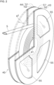
FIG. 2 is a partial cross-sectional diagonal view showing yarn prepreg being wound on a reel. -
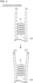
FIG. 3 is a schematic cross-sectional view showing a comparative example. -
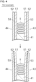
FIG. 4 is a schematic cross-sectional view showing a first example of a reel of this embodiment. -
FIG. 5 is a schematic cross-sectional view showing a second example of a reel of this embodiment. -
FIG. 6 is a schematic cross-sectional view showing a modification of the second example. -
FIG. 7 is a schematic cross-sectional view showing a third example of a reel of this embodiment. -
FIG. 8 is a schematic diagram showing a reel of another example that is used in the yarn prepreg manufacturing machine. -
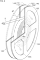
FIG. 9 is a partial cross-sectional diagonal view showing yarn prepreg being wound on the reel of another example. -
FIG. 10 is a schematic cross-sectional view showing the reel of another example. - First, a manufacturing method for manufacturing a yarn prepreg package will be described.
-
FIG. 1 shows a yarnprepreg manufacturing machine 1. This yarnprepreg manufacturing machine 1 is capable of manufacturingyarn prepreg 5 and winding theyarn prepreg 5 on areel 40 to manufacture ayarn prepreg package 60. - The yarn
prepreg manufacturing machine 1 has acarbon fiber supplier 11, aresin applier 12, and awinder 13. - The
carbon fiber supplier 11 can be set with a carbonfiber supply bobbin 3.Carbon fibers 4 released from the carbonfiber supply bobbin 3 travel downstream toward thewinder 13. - The
resin applier 12 hasrollers 31 that can rotate while immersed in the resin. Theresin applier 12 has a heating device (not shown) for heating the resin, which causes the resin to become liquid. Theroller 31 contacts thecarbon fibers 4 to adhere the resin to the surface of thecarbon fibers 4. - The
winder 13 can be set with thereel 40 for winding theyarn prepreg 5. Thewinder 13 drives thereel 40 by means of an electric motor, for example. This allows thereel 40 to wind theyarn prepreg 5. - As shown in
FIG. 2 , thereel 40 has a core 41, afirst guide 43, and asecond guide 44. - The
core 41 is formed, for example, in a cylindrical shape. Theyarn prepreg 5 can be wound onto the outer circumference of thecore 41. - The
first guide 43 is fixed to one end of the core 41 in the axial direction. Thesecond guide 44 is fixed to one end of the core 41 on the opposite side of thefirst guide 43 in the axial direction. Each of thefirst guide 43 and thesecond guide 44 is formed in a flange shape. Thefirst guide 43 and thesecond guide 44 guide theyarn prepreg 5 so that theyarn prepreg 5 is wound at an appropriate position on the outer circumference of thecore 41. - An axial gap is formed between the
first guide 43 and thesecond guide 44. The spacing g1 of this gap is the size of a small margin added to the width of theyarn prepreg 5 which is formed in a flattened shape. The size of the gap g1 is smaller than twice the width of theyarn prepreg 5. By guiding theyarn prepreg 5 between thefirst guide 43 and thesecond guide 44, theyarn prepreg 5 can be neatly spirally wound in a single row centered on thecore 41. - The
first guide 43 and thesecond guide 44 are each removable from thecore 41. The configuration for removably securing thefirst guide 43 and thesecond guide 44 to the core 41 can be realized, for example, by using bolts and nuts not shown. This makes it easy to manually adjust theyarn prepreg 5, even if the winding of theyarn prepreg 5 is disrupted. In addition, thefirst guide 43 and thesecond guide 44 are easier to clean and otherwise maintain. Only one of thefirst guide 43 and thesecond guide 44 may be removable from thecore 41. - The
first guide 43 and thesecond guide 44 are symmetrically configured and substantially similar. Accordingly, the configuration of thefirst guide 43 will be described below as representative. In the following description, the side of thereel 40 in the axial direction that is closer to the portion where theyarn prepreg 5 is wound onto the core 41 may be referred to as the inside in the axial direction, and the side that is farther away may be referred to as the outside in the axial direction. - The
first guide 43 has a first flange (first member) 51 and a second flange (second member) 52. - The
first flange 51 is a plate-shaped member formed in the shape of a flange. The thickness direction of thefirst flange 51 is parallel to the axial direction of thecore 41. Thefirst flange 51 is formed by a transparent synthetic resin. The material of thefirst flange 51 is preferably a filler-filled resin. However, the material of thefirst flange 51 can also be, for example, polycarbonate, polytetrafluoroethylene, polyethylene terephthalate, glass, or polyvinyl chloride. - The
second flange 52 is a plate-shaped member formed in the shape of a flange. The thickness direction of thesecond flange 52 is parallel to the axial direction of thecore 41. Thesecond flange 52 is located on the outside in the axial direction from thefirst flange 51. Thesecond flange 52 is arranged parallel to thefirst flange 51. Thesecond flange 52 is opaque. The material of thesecond flange 52 is preferably a metal, for example, aluminum. However, the material of thesecond flange 52 can also be, for example, iron, stainless steel, or the like. - At an appropriate location in the
second flange 52, a remainingamount check hole 55 is formed through thesecond flange 52 in the thickness direction. The remainingamount check hole 55 can be formed, for example, as a hole formed in the shape of a circular sector centered around the center of rotation of thereel 40. Thefirst flange 51 is exposed to the outside through this remainingamount check hole 55. Thus, the amount of theyarn prepreg 5 wound around thereel 40 can be easily checked from the side of thereel 40. Instead of the hole, a notch may be formed in thesecond flange 52 for checking the remaining amount. The notch can, for example, be formed elongated in the radial direction, extending from the outer edge of thesecond flange 52 toward the center of rotation. - As shown in the comparative example in
FIG. 3 , consider the case where, hypothetically, both thefirst guide 43 and thesecond guide 44 only comprise thefirst flanges 51 which are transparent. Theyarn prepreg 5, which is wound onto the core 41 in a hot condition, contacts or is in close proximity to thefirst flange 51, thus heating a surface of the inside of thefirst flange 51 in the axial direction. Since the thermal conductivity of thefirst flange 51 is not relatively high, a temperature gradient in the thickness direction is created within the material of thefirst flange 51, which is higher on the inside in the axial direction and lower as it approaches the outer side. - The portion of the inside of the
first flange 51 in the axial direction is hotter and therefore expands more in the radial direction. The portion of the outside of thefirst flange 51 in the axial direction is cooler and therefore expands less in the radial direction. As a result, the heat from theyarn prepreg 5 causes thefirst flange 51 to deform in such a way that it becomes axially outward as it approaches outward in the radial direction. If thefirst flange 51 is deformed in this manner, it is unable to guide theyarn prepreg 5 properly, so that, for example, it is wound around thereel 40 in such a way that it deviates from theyarn prepreg 5 already wound spirally in a single row. As a result, abrasion may occur during winding or unwinding of theyarn prepreg 5, causing it to break, etc. - Therefore, as shown in
FIG. 4 , thesecond flange 52 in this embodiment is provided on the outside from thefirst flange 51 in the axial direction. Thesecond flange 52 has a lower thermal expansion than a thermal expansion of thefirst flange 51. In other words, the coefficient of a linear expansion of thesecond flange 52 is smaller than that of thefirst flange 51. Furthermore, thesecond flange 52 has a higher thermal conductivity than a thermal conductivity of thefirst flange 51, so the temperature gradient as described for thefirst flange 51 is less likely to occur. As a result, thesecond flange 52 does not deform as much as thefirst flange 51. - The
second flange 52 is positioned on the outside from thefirst flange 51 in the axial direction. Therefore, even if the radially outer portion of thefirst flange 51 tries to deform axially outward, the deformation is restrained by thesecond flange 52. Therefore, the deformation of thefirst guide 43 as a whole can also be reduced. - In the example of
FIG. 4 , thefirst flange 51 and thesecond flange 52 are bonded to each other by a suitable adhesive. Although omitted inFIG. 2 ,FIG. 4 shows anadhesive layer 53. Thisadhesive layer 53 mechanically couples thefirst flange 51 and thesecond flange 52 to each other. Thus, thesecond flange 52 is able to better restrain the deformation of thefirst flange 51. - However, if the
first flange 51 and thesecond flange 52, which have different thermal expansions, are mechanically coupled by a surface, a large force may be applied to the coupled portion as a result of thermal deformation, which may cause damage. In addition, if strong deformation of thefirst flange 51 occurs, thesecond flange 52 may be deformed together with thefirst flange 51. Considering this, thefirst flange 51 and thesecond flange 52 can be configured not to be bonded together. - For example, as shown in
FIG. 5 , consider a configuration in which thefirst flange 51 and thesecond flange 52 are not bonded and are simply in contact with each other surface to surface. In this configuration, even if thefirst flange 51 is deformed so that it becomes outward in the axial direction as it approaches outward in the radial direction as a result of heat applied to it from theyarn prepreg 5, this deformation is suppressed by thesecond flange 52, which is relatively less deformed due to heat. Since thefirst flange 51 is not mechanically coupled to thesecond flange 52, the surfaces can slide against each other and allow the deformation of thefirst flange 51 to escape radially outward. - In the example of
FIG. 5 , the outer diameter of thefirst flange 51 is substantially equal to the outer diameter of thesecond flange 52. For example, as a modification shown inFIG. 6 , the outer diameter of thesecond flange 52 can be modified to be larger than the outer diameter of thefirst flange 51. Thefirst flange 51 located inside is closer to theyarn prepreg 5 than thesecond flange 52 located outside and is therefore more susceptible to thermal deformation. Even in the case where thefirst flange 51 is largely deformed, if the outer diameter of thesecond flange 52 is larger than the outer diameter of thefirst flange 51, the circumference of thefirst flange 51 can easily be prevented from being deformed so that it overcomes thesecond flange 52. The configuration in which the outer diameter of thesecond flange 52 is larger than the outer diameter of thefirst flange 51 can be similarly applied to the example inFIG. 4 which is described above and an example inFIG. 7 which will be described below. - As another example of a configuration in which the
first flange 51 and thesecond flange 52 are not bonded together, as shown inFIG. 7 , a small gap g2 can be formed between thefirst flange 51 and thesecond flange 52. The gap g2 can be achieved, for example, by placing aspacer 54 of an appropriate thickness between thefirst flange 51 and thesecond flange 52. In this configuration, as a result of heat from the yarn prepreg being applied to thefirst flange 51, thefirst flange 51 is deformed so that it becomes outward in the axial direction as it approaches outward in the radial direction. However, since thefirst flange 51 and thesecond flange 52 face each other with a gap g2, even if the above deformation occurs somewhat strongly in thefirst flange 51, only the outer edge of thefirst flange 51 in the radial direction contacts thesecond flange 52. Since the contact area is slight, it is difficult for heat to be conducted from thefirst flange 51 to thesecond flange 52. Therefore, heat-induced deformation of thesecond flange 52 can be significantly reduced. - In this embodiment, the axial length (spacing g1) of the
core 41 is about 6 mm and the diameter of thecore 41 is about 110 mm. The diameter of thefirst guide 43 and the second guide 44 (first flange 51 and second flange 52) is about 500 mm. The thickness of thefirst flange 51 is about 2 mm and the thickness of thesecond flange 52 is about 3 mm. However, the shape of thereel 40 can be modified in various ways. - As explained above, in this embodiment, the
yarn prepreg package 60 is manufactured in the following manner. Theyarn prepreg package 60 is formed by winding theyarn prepreg 5 onto thereel 40. Thereel 40 includes thefirst guide 43 and thesecond guide 44 which are arranged so that the spacing g1 is formed between thefirst guide 43 and thesecond guide 44. Each of thefirst guide 43 and thesecond guide 44 has thefirst flange 51 and thesecond flange 52, thesecond flange 52 being opaque. Thesecond flange 52 is located on the outside in the axial direction from thefirst flange 51. Thesecond flange 52 has a higher thermal conductivity than a thermal conductivity of thefirst flange 51. Theyarn prepreg 5 is led between thefirst guide 43 and thesecond guide 44 and wound spirally in a single row onto thereel 40. - This allows for good suppression of heat-induced deformation of the
first guide 43 and thesecond guide 44 that guide theyarn prepreg 5, and for stable maintenance of the parallelism of thefirst guide 43 and thesecond guide 44. Therefore, it is possible to produce theyarn prepreg package 60 in which theyarn prepreg 5 is neatly wound and to ensure good unwinding of theyarn prepreg 5 from the package. - In the
reel 40 of theyarn prepreg package 60 manufactured in this embodiment, thefirst flange 51 is transparent or translucent. Thefirst flange 51 is exposed outward in the axial direction through the remainingamount check hole 55 formed in a through shape at thesecond flange 52. - This allows the remaining amount of the
yarn prepreg 5 to be easily checked via the remainingamount check hole 55 formed at thesecond flange 52. - In the
reel 40 of theyarn prepreg package 60 manufactured in this embodiment, the thermal expansion of thesecond flange 52 is lower than the thermal expansion of thefirst flange 51. - This allows for even better suppression of heat-induced deformation of the
first guide 43 and thesecond guide 44. - In the
reel 40 of theyarn prepreg package 60 manufactured in this embodiment, thesecond flange 52 has higher rigidity than rigidity of thefirst flange 51. - This allows the
second flange 52 to strongly suppress the attempt of thefirst flange 51 to deform outward in the axial direction due to heat. - In the
reel 40 of theyarn prepreg package 60 manufactured in this embodiment, thefirst flange 51 has a lower relative density than a relative density of thesecond flange 52. - This allows the
reel 40 to be lightweight and easier to transport and otherwise handle. - In the example of
FIG. 4 , thefirst flange 51 and thesecond flange 52 are coupled to each other via theadhesive layer 53. - This allows for a good increase in the mechanical strength of the
first guide 43 and thesecond guide 44. - In the example of
FIG. 5 , thefirst flange 51 and thesecond flange 52 are in contact with each other face to face without being adhered. - This allows deformation of the
first flange 51 to be released without being transmitted to thesecond flange 52. Thus, damage to thefirst flange 51 and the like can be avoided and the durability of thereel 40 can be well enhanced. - In the example of
FIG. 7 , the air layer is formed between thefirst flange 51 and thesecond flange 52. - This prevents heat from being transferred from the
first flange 51 to thesecond flange 52, which effectively prevents thermal deformation of thesecond flange 52. - In the example in
FIG. 6 , the outer diameter of thesecond flange 52 is larger than the outer diameter of thefirst flange 51. - This makes it easier to prevent the peripheral edge of the
first flange 51 from deforming to overcome thesecond flange 52 outward in the axial direction, even if thefirst flange 51 is largely deformed. - The
reel 40 of theyarn prepreg package 60 manufactured in this embodiment has thecore 41. Theyarn prepreg 5 is wound around the outer circumference of thecore 41. Thefirst guide 43 and thesecond guide 44 are removable from thecore 41. - This allows easy access to the
yarn prepreg 5 wound onto thereel 40. In addition, thereel 40 is easy to maintain. - Next, another example of the yarn prepreg package will be described.
- As shown in
FIG. 8 , ayarn prepreg package 160 of another example can be manufactured by a yarnprepreg manufacturing machine 1 similar toFIG. 1 . With respect toFIG. 8 , members identical or similar to the aforementioned embodiments are marked with the same symbols in the drawings and may be omitted from the description. - As shown in
FIG. 9 , theyarn prepreg package 160 has areel 140. Thereel 140 has acore 141, afirst guide 143, and asecond guide 144. - The
core 141 is formed, for example, in a cylindrical shape. Theyarn prepreg 5 can be wound onto the outer circumference of thecore 141. - The
first guide 143 is fixed to one end of the core 141 in the axial direction. Thesecond guide 144 is fixed to one end of thecore 141 on the opposite side of thefirst guide 143 in the axial direction. Each of thefirst guide 143 and thesecond guide 144 is formed in a flange shape. Thefirst guide 143 and thesecond guide 144 guide theyarn prepreg 5 so that theyarn prepreg 5 is wound at an appropriate position on the outer circumference of thecore 141. Similar to thereel 40 described in the above embodiment, it is preferred that at least one of thefirst guide 143 and thesecond guide 144 can be removable from thecore 141. - Similar to the
reel 40 described in the above embodiment, a spacing g1 is formed in the axial direction between thefirst guide 143 and thesecond guide 144. - The
first guide 143 and thesecond guide 144 are symmetrically configured and substantially similar. Accordingly, the configuration of thefirst guide 143 will be described below as representative. - The
first guide 143 has a first flange (first member) 151 and a second flange (second member) 152. - The
first flange 151 is a plate-shaped member formed in the shape of a flange. The thickness direction of thefirst flange 151 is parallel to the axial direction of thecore 141. Thefirst flange 151 is formed by a transparent synthetic resin. The material of thefirst flange 151 is preferably filler-filled resin, polycarbonate, polytetrafluoroethylene, or polyethylene terephthalate. However, the material of thefirst flange 151 can also be glass, polyvinyl chloride, or the like. - The
second flange 152 is a plate-shaped member formed in the shape of a flange. The thickness direction of thesecond flange 152 is parallel to the axial direction of thecore 141. Thesecond flange 152 is located the outside in the axial direction from thefirst flange 151. Thesecond flange 152 is arranged parallel to thefirst flange 51. Thesecond flange 152 is opaque. The material of thesecond flange 152 is preferably a metal, for example, aluminum. However, the material of thesecond flange 152 can also be steel, stainless steel, or the like. - The
second flange 152 has a lower thermal expansion than a thermal expansion of thefirst flange 151. In other words, the coefficient of a linear expansion of thesecond flange 152 is smaller than that of thefirst flange 151. Furthermore, thesecond flange 152 has a higher thermal conductivity than a thermal conductivity of thefirst flange 151, so the temperature gradient as described for thefirst flange 151 is less likely to occur. As a result, thesecond flange 152 does not deform as much as thefirst flange 151. - As shown in
FIG. 10 , a small gap g2 is formed between thefirst flange 151 and thesecond flange 152. The gap g2 can be achieved, for example, by placing aspacer 154 of appropriate thickness between thefirst flange 151 and thesecond flange 152. In this configuration, as a result of heat from the yarn prepreg being applied to thefirst flange 151, thefirst flange 151 is deformed so that it becomes outward in the axial direction as it approaches outward in the radial direction. However, since thefirst flange 151 and thesecond flange 152 face each other with a gap g2, even if the above deformation occurs somewhat strongly in thefirst flange 151, only the outer edge of thefirst flange 151 in the radial direction contacts thesecond flange 152. Since the contact area is slight, it is difficult for heat to be conducted from thefirst flange 151 to thesecond flange 152. Therefore, heat-induced deformation of thesecond flange 152 can be significantly reduced. - As explained above, the
reel 140 as the example shown inFIGS. 8 through 10 is a reel for winding theyarn prepreg 5. Thisreel 140 has thefirst guide 143 and thesecond guide 144 which are arranged so that the spacing is formed between thefirst guide 143 and thesecond guide 144. Each of thefirst guide 143 and thesecond guide 144 has thefirst flange 151 which is transparent and thesecond flange 152 which is opaque. Thesecond flange 152 is located on the outside from thefirst flange 151 in the axial direction. Thefirst flange 151 is exposed outward in the axial direction through a remainingamount check hole 155 formed in a through shape at thesecond flange 152. The air layer is formed in the gap g2 between thefirst flange 151 and thesecond flange 152. - This allows good suppression of heat-induced deformation of the
first guide 143 and thesecond guide 144 that guide theyarn prepreg 5, and for stable maintenance of the parallelism of thefirst guide 143 and thesecond guide 144. In particular, heat is less likely to be transferred from thefirst flange 151 to thesecond flange 152, and heat-induced deformation is less likely to occur in thesecond flange 152. Therefore, it is possible to produce a yarn prepreg package in which theyarn prepreg 5 is neatly wound and to ensure good unwinding of theyarn prepreg 5 from the package. - In the
reel 140 of the above example, the thermal expansion of thesecond flange 152 is lower than the thermal expansion of thefirst flange 151. - This allows for even better suppression of heat-induced deformation of the
first guide 143 and thesecond guide 144. - In the
reel 140 of the above example, thesecond flange 152 has more rigidity than rigidity of thefirst flange 151. - This allows the
second flange 152 to strongly suppress the attempt of thefirst flange 151 to deform outward in the axial direction due to heat. - In the
reel 140 of the above example, thefirst flange 151 has a lower relative density than a relative density of thesecond flange 152. - This allows the
reel 140 to be lightweight and easier to transport and otherwise handle. - The
reel 140 of the above example has the core 141 whose outer circumference is wound by theyarn prepreg 5. Each of thefirst guide 143 and thesecond guide 144 can be removed from thecore 141. - This allows easy access to the
yarn prepreg 5 wound onto thereel 140. In addition, thereel 140 is easy to maintain. - While some preferred embodiments of the present invention have been described above, the foregoing configurations may be modified, for example, as follows. The modification can be singly made and any combination of several modifications can be made.
- The
first flange 51 is not limited to being transparent, and may be configured to be translucent, for example. It is sufficient if thefirst flange 51 is transparent to the extent that theyarn prepreg 5 wound around thecore 41 is visible. - The relative density of the
first flange 51 is preferably less than that of thesecond flange 52, but may be greater than that of thesecond flange 52. - The layered structure with the
first flange 51 which is transparent and thesecond flange 52 which is opaque may be applied to only one side of thefirst guide 43 and thesecond guide 44. - In the case where the layered structure with the
first flange 51 which is transparent and thesecond flange 52 which is opaque is applied to both thefirst guide 43 and thesecond guide 44, a hole or notch for checking the remaining amount may be formed only on thesecond flange 52 on one side. - The
first flange 51 may be configured to be opaque. - Instead of the
first flange 51, a sheet-like or film-like member may be used. - Between the
first guide 43 and thesecond guide 44, theyarn prepreg 5 may be wound while being traversed with a small stroke with respect to thecore 41 of thereel 40. If the traverse width is smaller than the width of theyarn prepreg 5, theyarn prepreg 5 will be wound spirally on thereel 40 in a single row. - Traversing can be achieved, for example, by forming a ring-shaped guide groove on the periphery of a
guide roller 14, which is located immediately upstream of thereel 40 shown inFIG. 1 and guides theyarn prepreg 5, and theguide roller 14 reciprocates in a small stroke in the axial direction as it rotates. Instead of theguide roller 14, thereel 40 can move with small strokes in the axial direction. Traversing can also be achieved by forming the guide groove of theguide roller 14 in a spiral shape. - The
first flange 151 is not limited to being transparent and may be configured to be translucent, for example. It is sufficient if thefirst flange 151 is transparent to the extent that theyarn prepreg 5 wound around thecore 141 is visible. - The relative density of the
first flange 151 is preferably less than that of thesecond flange 152, but may be greater than that of thesecond flange 152. - The layered structure with the
first flange 151 which is transparent and thesecond flange 152 which is opaque may be applied to only one side of thefirst guide 143 and thesecond guide 144. - In the case where the layered structure with the
first flange 151 which is transparent and thesecond flange 152 which is opaque is applied to both thefirst guide 143 and thesecond guide 144, a hole or notch for checking the remaining amount may be formed only on thesecond flange 152 on one side. - Instead of the
first flange 151, a sheet-like or film-like member may be used. - Between the
first guide 143 and thesecond guide 144, theyarn prepreg 5 may be wound while being traversed with a small stroke with respect to thecore 141 of thereel 140. If the traverse width is smaller than the width of theyarn prepreg 5, theyarn prepreg 5 will be wound spirally on thereel 140 in a single row. - Traversing can be achieved, for example, by forming a ring-shaped guide groove on the periphery of the
guide roller 14, which is located immediately upstream of thereel 140 shown inFIG. 8 and guides theyarn prepreg 5, and theguide roller 14 reciprocates in a small stroke in the axial direction as it rotates. Instead of theguide roller 14, thereel 140 can move with small strokes in the axial direction. Traversing can also be achieved by forming the guide groove of theguide roller 14 in a spiral shape. - In the configuration shown in
FIGS. 1 and8 , for example, pitch fiber, PAN fiber, or the like can be used as the carbon fibers pre-wound on the carbonfiber supply bobbin 3. PAN is an abbreviation for polyacrylonitrile. - In the yarn
prepreg manufacturing machine 1 shown inFIGS. 1 and8 , carbon fibers are supplied in thecarbon fiber supplier 11 from the carbonfiber supply bobbin 3 on which premanufactured carbon fibers are wound. Instead of this, the configuration can be changed to one in which carbon fibers are manufactured and supplied from raw materials in thecarbon fiber supplier 11. How the carbon fibers are manufactured is arbitrary, but for example, coal tar could be converted into pitch fibers or acrylonitrile into PAN fibers. - Regarding the
resin applier 12, there are various methods of adhering the resin to the carbon fibers. For example, the resin may be impregnated onto the carbon fibers by roll transfer, the resin may be supplied to the carbon fibers by a metering pump, the carbon fibers may be immersed in a resin reservoir in which liquid resin is stored. - The configuration of the yarn
prepreg manufacturing machine 1 shown inFIGS. 1 and8 is an example and may be modified as needed. -
5 yarn prepreg 140 reel 40 reel 143 guide 43 guide 151 first flange 51 first flange 152 second flange 52 second flange 160 yarn prepreg package 53 adhesive layer g1 spacing 60 yarn prepreg package g2 gap
Claims (15)
- A yarn prepreg package manufacturing method to form a yarn prepreg package in which yarn prepreg is wound onto a reel,the reel including two guides which are arranged so that a spacing is formed between the two guides,at least one of the guides including:a first member; anda second member which is located on an outside in an axial direction from the first member, is opaque, and is formed in a flange shape,the second member having a higher thermal conductivity than a thermal conductivity of the first member,the method comprising:
leading the yarn prepreg between the two guides to wind the yarn prepreg spirally in a single row onto the reel. - The yarn prepreg package manufacturing method according to claim 1, whereinthe first member is transparent or translucent, andthe first member is exposed outward in the axial direction through a hole or notch formed in a through shape at the second member.
- The yarn prepreg package manufacturing method according to claim 1 or 2, wherein a thermal expansion of the second member is lower than a thermal expansion of the first member.
- The yarn prepreg package manufacturing method according to any one of claims 1 to 3, wherein the second member has higher rigidity than rigidity of the first member.
- The yarn prepreg package manufacturing method according to any one of claims 1 to 4, wherein the first member has a lower relative density than a relative density of the second member.
- The yarn prepreg package manufacturing method according to any one of claims 1 to 5, wherein the first member and the second member are coupled to each other via an adhesive layer.
- The yarn prepreg package manufacturing method according to any one of claims 1 to 6, wherein the first member and the second member are in contact with each other face to face without being adhered.
- The yarn prepreg package manufacturing method according to any one of claims 1 to 7, wherein an air layer is formed between the first member and the second member.
- The yarn prepreg package manufacturing method according to any one of claims 1 to 8, wherein an outer diameter of the second member is larger than an outer diameter of the first member.
- The yarn prepreg package manufacturing method according to any one of claims 1 to 9, whereinthe reel includes a core whose outer circumference is wound by the yarn prepreg, andat least one of the two guides is removable from the core.
- A yarn prepreg reel for winding yarn prepreg, comprisingtwo guides which are arranged so that a spacing is formed between the two guides, whereinat least one of the guides includes:a first member which is transparent or translucent; anda second member which is located on an outside in an axial direction from the first member, is opaque, and is formed in a flange shape,the first member is exposed outward in the axial direction through a hole or notch formed in a through shape at the second member, andan air layer is formed between the first member and the second member.
- The yarn prepreg reel according to claim 11, wherein a thermal expansion of the second member is lower than a thermal expansion of the first member.
- The yarn prepreg reel according to claim 11 or 12, wherein the second member has higher rigidity than rigidity of the first member.
- The yarn prepreg reel according to any one of claims 11 to 13, wherein the first member has a lower relative density than a relative density of the second member.
- The yarn prepreg reel according to any one of claims 11 to 14, further comprisinga core whose outer circumference is wound by the yarn prepreg, whereinat least one of the two guides is removable from the core.
Applications Claiming Priority (2)
| Application Number | Priority Date | Filing Date | Title |
|---|---|---|---|
| JP2022100249 | 2022-06-22 | ||
| PCT/JP2023/021070 WO2023248790A1 (en) | 2022-06-22 | 2023-06-06 | Yarn prepreg package production method and reel for yarn prepreg |
Publications (2)
| Publication Number | Publication Date |
|---|---|
| EP4545462A1 true EP4545462A1 (en) | 2025-04-30 |
| EP4545462A4 EP4545462A4 (en) | 2026-06-17 |
Family
ID=89379881
Family Applications (1)
| Application Number | Title | Priority Date | Filing Date |
|---|---|---|---|
| EP23826977.3A Pending EP4545462A4 (en) | 2022-06-22 | 2023-06-06 | Yarn prepreg packaging process and yarn prepreg spool |
Country Status (6)
| Country | Link |
|---|---|
| US (1) | US20260200692A1 (en) |
| EP (1) | EP4545462A4 (en) |
| JP (1) | JP7806237B2 (en) |
| KR (1) | KR20250005433A (en) |
| CN (1) | CN119384388A (en) |
| WO (1) | WO2023248790A1 (en) |
Family Cites Families (11)
| Publication number | Priority date | Publication date | Assignee | Title |
|---|---|---|---|---|
| US3960626A (en) * | 1971-01-08 | 1976-06-01 | Martin Marietta Corporation | Method of making high performance ablative tape |
| JPS57151355U (en) * | 1981-03-16 | 1982-09-22 | ||
| SE453489B (en) * | 1983-10-17 | 1988-02-08 | Stig Ernst Erik Olofsson | SPOOL |
| JPH09169861A (en) | 1995-12-20 | 1997-06-30 | Mitsubishi Rayon Co Ltd | Thermosetting tow prepreg package |
| JP3059762U (en) * | 1998-12-10 | 1999-07-13 | アイシート工業株式会社 | Tape reel |
| JP3333166B2 (en) * | 2000-02-10 | 2002-10-07 | 株式会社ハーモニ産業 | Warp delivery mechanism of loom |
| JP2006069689A (en) * | 2004-08-31 | 2006-03-16 | Kyoraku Co Ltd | Electric wire drum |
| US20080061187A1 (en) * | 2006-09-07 | 2008-03-13 | Couchey Brian P | Reel assembly |
| CN105636890B (en) * | 2013-09-27 | 2019-11-08 | 康宁光电通信有限责任公司 | Reeling apparatus and method for winding a length of cable |
| CN108839360B (en) * | 2018-07-24 | 2019-11-08 | 浙江大学 | A wire roll installation device for composite material automatic laying equipment |
| JP7595411B2 (en) * | 2019-11-22 | 2024-12-06 | デクセリアルズ株式会社 | Reel parts, adhesive film rolls |
-
2023
- 2023-06-06 WO PCT/JP2023/021070 patent/WO2023248790A1/en not_active Ceased
- 2023-06-06 EP EP23826977.3A patent/EP4545462A4/en active Pending
- 2023-06-06 KR KR1020247039863A patent/KR20250005433A/en active Pending
- 2023-06-06 US US18/877,082 patent/US20260200692A1/en active Pending
- 2023-06-06 JP JP2024528750A patent/JP7806237B2/en active Active
- 2023-06-06 CN CN202380047086.0A patent/CN119384388A/en active Pending
Also Published As
| Publication number | Publication date |
|---|---|
| KR20250005433A (en) | 2025-01-09 |
| WO2023248790A1 (en) | 2023-12-28 |
| EP4545462A4 (en) | 2026-06-17 |
| CN119384388A (en) | 2025-01-28 |
| US20260200692A1 (en) | 2026-07-16 |
| JP7806237B2 (en) | 2026-01-26 |
| TW202400699A (en) | 2024-01-01 |
| JPWO2023248790A1 (en) | 2023-12-28 |
Similar Documents
| Publication | Publication Date | Title |
|---|---|---|
| US20170291352A1 (en) | Manufacturing method of tank | |
| JP6423303B2 (en) | Manufacturing apparatus and manufacturing method for fiber reinforced thermoplastic resin tape | |
| CN104284854B (en) | Method and system for preventing wrinkling in a web being fed through a hopper | |
| JP5412733B2 (en) | Sheet take-up device | |
| CN105849021B (en) | Spool | |
| JP5315884B2 (en) | Sheet-like material conveying method and conveying apparatus, and sheet-like material winding body manufacturing method | |
| US20110048991A1 (en) | Loaded film cassette for gaseous vapor deposition | |
| KR20200024659A (en) | Filament winding apparatus | |
| US7475844B2 (en) | Web winding device and spacer | |
| JP7806237B2 (en) | Method for manufacturing yarn prepreg package and reel for yarn prepreg | |
| EP4375037B1 (en) | Method for producing sheet molding compound, dispersion roller device, and apparatus for producing sheet molding compound | |
| WO2014021392A1 (en) | Reel member, film container, and method for manufacturing film container | |
| KR20150113836A (en) | Conveyor roll and method for making the same | |
| JP6375997B2 (en) | Filament winding equipment | |
| CN113492540A (en) | Filament winding device, system for manufacturing molded body, and method for manufacturing molded body | |
| JP2002235270A (en) | Cylindrical body containing felt material, method for producing the same, and jig used for the production | |
| CN107532697B (en) | Screw shaft, method for manufacturing the same, and ball screw device | |
| US8534591B2 (en) | Apparatus and method for loading a film cassette for gaseous vapor deposition | |
| TWI658217B (en) | Sheet manufacturing roller | |
| JP6361551B2 (en) | Filament winding equipment | |
| JP2012201471A (en) | Winding core for web | |
| US20160251195A1 (en) | Reel member and film accommodating body | |
| JPH06206668A (en) | Web core | |
| EP4716072A1 (en) | Manufacturing method for rotary electric machine protection ring and manufacturing device for rotary electric machine protection ring | |
| TWI778531B (en) | Release film roll, ceramic part sheet and method for producing the same, and ceramic part and method for producing the same |
Legal Events
| Date | Code | Title | Description |
|---|---|---|---|
| STAA | Information on the status of an ep patent application or granted ep patent |
Free format text: STATUS: THE INTERNATIONAL PUBLICATION HAS BEEN MADE |
|
| PUAI | Public reference made under article 153(3) epc to a published international application that has entered the european phase |
Free format text: ORIGINAL CODE: 0009012 |
|
| STAA | Information on the status of an ep patent application or granted ep patent |
Free format text: STATUS: REQUEST FOR EXAMINATION WAS MADE |
|
| 17P | Request for examination filed |
Effective date: 20250109 |
|
| AK | Designated contracting states |
Kind code of ref document: A1 Designated state(s): AL AT BE BG CH CY CZ DE DK EE ES FI FR GB GR HR HU IE IS IT LI LT LU LV MC ME MK MT NL NO PL PT RO RS SE SI SK SM TR |
|
| DAV | Request for validation of the european patent (deleted) | ||
| DAX | Request for extension of the european patent (deleted) | ||
| A4 | Supplementary search report drawn up and despatched |
Effective date: 20260520 |
|
| RIC1 | Information provided on ipc code assigned before grant |
Ipc: B65H 75/14 20060101AFI20260513BHEP Ipc: B65H 54/12 20060101ALI20260513BHEP Ipc: C08J 5/24 20060101ALI20260513BHEP |