EP4545461A1 - Strip rebound absorber and packaging machine - Google Patents
Strip rebound absorber and packaging machine Download PDFInfo
- Publication number
- EP4545461A1 EP4545461A1 EP24206554.8A EP24206554A EP4545461A1 EP 4545461 A1 EP4545461 A1 EP 4545461A1 EP 24206554 A EP24206554 A EP 24206554A EP 4545461 A1 EP4545461 A1 EP 4545461A1
- Authority
- EP
- European Patent Office
- Prior art keywords
- strip
- roller
- packaging material
- rod
- absorber
- Prior art date
- Legal status (The legal status is an assumption and is not a legal conclusion. Google has not performed a legal analysis and makes no representation as to the accuracy of the status listed.)
- Pending
Links
Images




Classifications
-
- B—PERFORMING OPERATIONS; TRANSPORTING
- B65—CONVEYING; PACKING; STORING; HANDLING THIN OR FILAMENTARY MATERIAL
- B65H—HANDLING THIN OR FILAMENTARY MATERIAL, e.g. SHEETS, WEBS, CABLES
- B65H23/00—Registering, tensioning, smoothing or guiding webs
- B65H23/04—Registering, tensioning, smoothing or guiding webs longitudinally
- B65H23/16—Registering, tensioning, smoothing or guiding webs longitudinally by weighted or spring-pressed movable bars or rollers
-
- B—PERFORMING OPERATIONS; TRANSPORTING
- B65—CONVEYING; PACKING; STORING; HANDLING THIN OR FILAMENTARY MATERIAL
- B65H—HANDLING THIN OR FILAMENTARY MATERIAL, e.g. SHEETS, WEBS, CABLES
- B65H2801/00—Application field
- B65H2801/69—Form fill-and-seal machines
Definitions
- the present invention relates to a strip rebound absorber and a packaging machine comprising the strip rebound absorber.
- the invention is applicable in packaging machines for producing packages.
- these types of packages are manufactured using fully automated packaging apparatuses.
- These apparatuses typically shape the packaging material into a tube form and then fill it with the pourable product under strictly aseptic conditions. Subsequently, the material is folded and cut to create individually sealed packages.
- the packaging material itself exhibits a multilayered structure, which typically includes a core layer comprising materials like paper or cardboard. This core layer is enveloped on both sides with layers of heat-sealing plastic materials, such as polyethylene.
- this packaging apparatus there is a packaging material web coil and a plastic strip coil which need to be joined together for producing the sealed packages and the plastic strip is joined to the packaging material web so as to be inside the package, i.e. in contact with the product.
- the sealing occurs in two steps.
- a first longitudinal portion of the plastic strip is overlapped to a first longitudinal portion of packaging material web and then both portions are welded together.
- a second longitudinal potion of the plastic strip is overlapped to a second longitudinal portion of packaging material web, different from the first portion, and the two portions are sealed together by means of a longitudinal sealing forming the tube structure.
- Sealing is typically accomplished through induction heating or hot air techniques. Insufficient tensioning of the strip may result in strip sealing misalignment that might cause improper adhesion to the packaging material web.
- An object of the present invention is therefore to address the aforementioned need by providing a strip rebound absorber and a packaging machine comprising the strip rebound absorber that minimizes a strip tensioning fluctuation ensuring a more effective application of a strip to material web packaging compared to known solutions.
- the strip rebound absorber In case of strip tension variations such as sudden peaks or decreases, as a consequence of machine behaviors or external disturbances, the strip rebound absorber is able to absorb the fluctuations.
- an object of the present invention is to provide a strip rebound absorber in a packaging machine that reduces the production of defective packages, consequently minimizing waste and material wastage.
- the invention concerns a strip rebound absorber 1 (for maintaining the tensioning of a strip S).
- the strip rebound absorber 1 comprises a first roller 2 rotatable around a first axis A2.
- the first roller 2 has a first receiving portion 3 for receiving the strip S.
- the first roller 2 is movable between a first position P1 and a second position P2.
- the strip rebound absorber may work at any position between P1, P2.
- the first roller 2 can occupy a working position P3 (illustrated in figure 2 ) located between the first position P1 and the second position P2.
- a standard working position may be defined as third position P3.
- the third position P3 may be substantially median with respect to the first and second positions P1, P2.
- the strip rebound absorber works in the position P3, with the possibility to filter tension variations (drop and increase).
- the strip rebound absorber 1 comprises an elastic element 5.
- the elastic element 5 is operatively coupled, directly or indirectly, with the first roller 2.
- the elastic element 5 and the first roller 2 are connected in a way that allows them to cooperate or mutually influence each other to perform a specific operation or function.
- the elastic element 5 is configured for moving, as a reaction to a variation of a tensional state of the strip upstream the first roller 2 according to a direction D1 of feeding of the strip S, between at least a first configuration 5A, wherein the first roller 2 is in the first position P1, and a second configuration 5B, wherein the first roller 2 is in the second position P2.
- the elastic element 5 reacts to the tension variation of the strip S.
- the position P1 can be reached if a tensioning occurs; similarly, for de-tensioning, the system responds by compensating the downstream increment, transitioning from configuration P3 to P1.
- the first roller 2 moves towards the second position P2 in cases where the strip upstream of the first roller 2 experiences a reduction in tension, it becomes feasible to rectify the tensional variation by halting the propagation of de-tensioning downstream of the first roller 2.
- the strip has a first tensional state downstream the first roller 2.
- the first roller 2 moves towards the second position P2 thanks to the movement of the elastic element 5 towards the second configuration 5B.
- the elastic element 5 is a spring 10.
- the spring 10 is a linear spring.
- the spring 10 is preloaded for rebound.
- the spring 10 has been tensioned (i.e. extended with respect to its home or zero potential energy position) prior to its actual intended use in such a way that it stores potential energy, which will be released when the spring is allowed to return to its original state.
- the preload ensures that the spring starts in a tensioned state, ready to exert a force in the opposite direction when released.
- the spring 10 has a first end 11 and a second end 12.
- the second end 12 of the spring 10 can be fixed to a frame F.
- the spring 10 When the first roller 2 is in the first position P1 the spring 10 has a first length L1 and when the first roller 2 is in the second position P2 the spring 10 has a second length L2.
- the second length L2 is shorter than the length L1.
- the motion of the spring 10 causes the motion of the first roller between the first position P1 and the second position P2.
- the strip rebound absorber 1 may comprise a rod 6 pivotable around a second axis A6.
- the rod 6 has a first end 6A and a second end 6B, opposite to each other.
- the first roller 2 is fixed to the rod 6.
- the first roller 2 is fixed to the first end 6A of the rod 6.
- the elastic element 5 is operatively coupled with the rod 6, preferably at a second end 6B of the rod opposite to the first end 6A.
- the strip rebound absorber 1 comprises first coupling means M1 for coupling the rod 6 with the first roller 2.
- the first coupling means M1 comprises a first bolt 20.
- the elastic element 5 is coupled to the second end 6B of rod 6.
- the strip rebound absorber 1 comprises second coupling means M2 for coupling the second end 6B of the rod with the elastic element 5.
- the second coupling means M2 may comprises a bolt or a pin.
- the second coupling means M2 comprises a second bolt 30 and the first end 11 of the spring 10 can be wound around the bolt 30. As shown in figure 1 , when the elastic element 5 is in the first configuration 5A, the rod is in a position P4.
- the rod 6 In the case the strip S is correctly tensioned, the rod 6 is in a standard working position P6 to which the rod 6 tends to return.
- the standard working position P6 is placed between the position P4 and the position P5.
- the rod 6 and the roller 2 oscillates around the respective working position P6 for the rod 6 and P3 for the roller 2.
- the position of the roller 2 oscillates around a working position P3.
- the rod 6 moves from the standard working position P6 to the correction position P5, pivoting around the second axis A6 according to a first rod rotation verse R1.
- the rod 6 moves from the correction position P5 to the standard working position P6, pivoting around the second axis A6 according to a second rod rotation verse R2, opposite of the first rotation verse R1.
- the first rod rotation verse R1 is a contraclockwise clock verse and the second rod rotation verse R2 is a clockwise verse.
- the strip rebound absorber 1 comprises a second roller 7 rotatable around a third axis A7.
- the second roller 7 has a second receiving portion 8 for receiving the strip S.
- the second roller 7 is arranged downstream of the first roller according to the direction D1 of feeding of the strip.
- the second roller 7 is positioned at a fixed distance with respect to the first roller 2.
- the second roller 7 is fixed to the frame F.
- the first roller 2 moves with respect to the second roller 7.
- the first roller 2 has a first lateral face 2A and the second roller 7 has a second lateral face 7A.
- the first lateral face 2A is preferably coplanar to the second lateral face 7A.
- the rod 6 is pivotable around a shaft and the second roller 7 is (pivotally) coupled to the shaft.
- the shaft is part of the frame F.
- the pivoting of the rod 6 is independent from the pivoting of the second roller 7.
- the second roller 7 is free from actuating forces and it rotates only due to movement of the strip S thereon.
- the second axis A6 coincides with the third axis A7.
- the second roller 7 is coaxial with the rod 6.
- the strip rebound absorber comprises at least a limiting element 9A, 9B for limiting the movement of the first roller 2 between the first position P1 and the second position P2.
- the at least one limiting element comprises a first limiting element 9A is configured for limiting the movement of the first roller 2 along a direction of movement (preferably anticlockwise) from the first position P1 to the second position P2.
- the at least one limiting element comprises a second limiting element 9B is configured for limiting the movement of the first roller 2 along a direction of movement (preferably clockwise) from the second position P2 to the first position P1.
- the limiting elements prevent spring yielding.
- the at least one limiting element 9A, 9B is configured for limiting a rotation of the rod 6.
- the first limiting 9A element is configured for limiting a rotation of the rod 6 according to the first rotation verse R1.
- the second limiting 9B element is configured for limiting a rotation of the rod 6 according to the second rotation verse R2.
- the first limiting 9A element is a first pin.
- the second limiting 9B element is a second pin.
- the first limiting 9A element ensures that the spring 10 keeps a slight pretensioning so that the spring 10 does not completely discharge.
- the second limiting 9B element ensures that the spring 10 does not exceed the maximum allowable working length, avoiding going beyond the yield load.
- the invention concerns a packaging machine 100 comprising:
- the buffer 102 is a gravity dancer collecting the unrolled strip S of the coil 101.
- the buffer 102 may be configured to maintain a predetermined speed of the strip S downstream of the buffer 102 with respect to the strip advancement direction, e.g. during a splice event.
- the buffer 102 sets the tension to which the strip S is subjected, e.g. during events during operation of the packaging machine.
- the packaging machine 100 comprises a coil or reel 110 of packaging material M.
- the packaging machine 100 may comprise a sealing device 103, arranged downstream of the coil of packaging material 110 and downstream of a buffer 102 according to the direction D1 of feeding of the strip.
- the sealing device 103 is configured to join the strip S to the packaging material M identifying a packaging material web W.
- the strip S can be sealed to the packaging material M, e.g. by induction heating or via hot air jet.
- the packaging machine 100 may comprise a sterilisation device 104, arranged downstream of the sealing device 103 according to a direction D2 of feeding of the packaging material web.
- the sterilisation device 104 is configured to sterilize the packaging material web W.
- the packaging machine 100 may comprise a folding, sealing and filling station 105, arranged downstream of the sterilisation device 104 according to a direction D2 of feeding of the packaging material web W.
- the folding, sealing and filling station 105 comprises means for folding and sealing the packaging material web W into a tube, and filling with a product the tube.
- the packaging machine 100 may comprise a transversal sealing and cutting station, arranged downstream of the folding, sealing and filling station 105 according to a direction D2 of feeding of the packaging material web or tube, comprising transversal sealing and cutting means configured for splitting the tube into a plurality of packages P.
Landscapes
- Containers And Plastic Fillers For Packaging (AREA)
Abstract
Strip rebound absorber comprising:
- a first roller (2) rotatable around a first axis (A2), the first roller (2) having a first receiving portion (3) for receiving a strip (S), the first roller (2) is movable between at least a first position (P1) and a second position (P2),
- an elastic element (5) operatively coupled with the first roller (2), the elastic element (5) being movable, as a reaction to a variation of a tensional state of the strip (S) upstream the first roller (2) according to a direction (D1) of feeding of the strip (S), between at least a first configuration (5A), wherein the first roller (2) is in the first position (P1), and a second configuration (5B), wherein the first roller (2) is in the second position (P2).
- a first roller (2) rotatable around a first axis (A2), the first roller (2) having a first receiving portion (3) for receiving a strip (S), the first roller (2) is movable between at least a first position (P1) and a second position (P2),
- an elastic element (5) operatively coupled with the first roller (2), the elastic element (5) being movable, as a reaction to a variation of a tensional state of the strip (S) upstream the first roller (2) according to a direction (D1) of feeding of the strip (S), between at least a first configuration (5A), wherein the first roller (2) is in the first position (P1), and a second configuration (5B), wherein the first roller (2) is in the second position (P2).
Description
- The present invention relates to a strip rebound absorber and a packaging machine comprising the strip rebound absorber.
- In particular, the invention is applicable in packaging machines for producing packages.
- In the following, we will refer to the technical field of packaging machines. Many liquid or pourable food products, such as fruit juice, UHT (ultra-high temperature treated) milk, wine, tomato sauce, etc., are commonly packaged using materials designed for this purpose.
- Typically, these types of packages are manufactured using fully automated packaging apparatuses.
- These apparatuses typically shape the packaging material into a tube form and then fill it with the pourable product under strictly aseptic conditions. Subsequently, the material is folded and cut to create individually sealed packages.
- The packaging material itself exhibits a multilayered structure, which typically includes a core layer comprising materials like paper or cardboard. This core layer is enveloped on both sides with layers of heat-sealing plastic materials, such as polyethylene.
- Generally, in this packaging apparatus there is a packaging material web coil and a plastic strip coil which need to be joined together for producing the sealed packages and the plastic strip is joined to the packaging material web so as to be inside the package, i.e. in contact with the product.
- The sealing occurs in two steps.
- In a first step, a first longitudinal portion of the plastic strip is overlapped to a first longitudinal portion of packaging material web and then both portions are welded together.
- Subsequently, a second longitudinal potion of the plastic strip is overlapped to a second longitudinal portion of packaging material web, different from the first portion, and the two portions are sealed together by means of a longitudinal sealing forming the tube structure.
- Sealing is typically accomplished through induction heating or hot air techniques. Insufficient tensioning of the strip may result in strip sealing misalignment that might cause improper adhesion to the packaging material web.
- In light of the above, it is crucial to reduce any fluctuations in terms of strip tension before attaching it to the packaging material web to guarantee a proper bond between the strip and the packaging material web, thereby preventing the occurrence of defective packages.
- An object of the present invention is therefore to address the aforementioned need by providing a strip rebound absorber and a packaging machine comprising the strip rebound absorber that minimizes a strip tensioning fluctuation ensuring a more effective application of a strip to material web packaging compared to known solutions.
- In case of strip tension variations such as sudden peaks or decreases, as a consequence of machine behaviors or external disturbances, the strip rebound absorber is able to absorb the fluctuations.
- Furthermore, an object of the present invention is to provide a strip rebound absorber in a packaging machine that reduces the production of defective packages, consequently minimizing waste and material wastage.
- The technical features of the invention, in accordance with the stated objectives, are clearly discernible from the content of the appended claims.
- The advantages of the invention will be more conspicuously evident in the ensuing detailed description, accompanied by reference to the appended drawings, which represent a purely exemplary and non-limiting embodiment, wherein:
-
Figure 1 schematically depicts a front view of a strip rebound absorber in a first configuration, in accordance with the description; -
Figure 2 schematically depicts a front view of a strip rebound in a second configuration, in accordance with the description; -
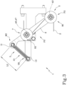
Figure 3 schematically depicts a front view of a strip rebound absorber in a third configuration, in accordance with the description; -
Figure 4 schematically depicts a perspective view of the strip rebound absorber offigure 1 , in accordance with the description; -
Figure 5 schematically depicts a perspective view of the strip rebound absorber offigure 3 , in accordance with the description; -
Figure 6 shows, a block diagram of a packaging machine, in accordance with the description. - The invention concerns a strip rebound absorber 1 (for maintaining the tensioning of a strip S).
- The strip rebound absorber 1 comprises a
first roller 2 rotatable around a first axis A2. - The
first roller 2 has a first receivingportion 3 for receiving the strip S. - As shown in
figure 1 and3 , thefirst roller 2 is movable between a first position P1 and a second position P2. - The strip rebound absorber may work at any position between P1, P2. The
first roller 2 can occupy a working position P3 (illustrated infigure 2 ) located between the first position P1 and the second position P2. - A standard working position may be defined as third position P3.
- As shown in
figure 2 , the third position P3 may be substantially median with respect to the first and second positions P1, P2. - Advantageously, the strip rebound absorber works in the position P3, with the possibility to filter tension variations (drop and increase).
- The strip rebound absorber 1 comprises an
elastic element 5. - The
elastic element 5 is operatively coupled, directly or indirectly, with thefirst roller 2. - In other words, the
elastic element 5 and thefirst roller 2 are connected in a way that allows them to cooperate or mutually influence each other to perform a specific operation or function. - The
elastic element 5 is configured for moving, as a reaction to a variation of a tensional state of the strip upstream thefirst roller 2 according to a direction D1 of feeding of the strip S, between at least afirst configuration 5A, wherein thefirst roller 2 is in the first position P1, and asecond configuration 5B, wherein thefirst roller 2 is in the second position P2. - In other words, the
elastic element 5 reacts to the tension variation of the strip S. - When the
roller 2 is in the second position P2 theelastic element 5 is in a home position with a preload, that is a minimum working stroke. - On the contrary when the
roller 2 is in the first position P1 theelastic element 5 is at maximum working stroke. - When a strip fluctuation causing a de-tensioning occurs upstream of the system, the
first roller 2 moves towards the second position P2. - When a strip fluctuation causing an increase in tension occurs upstream of the system, the
first roller 2 moves towards the first position P1. - In other words, the position P1 can be reached if a tensioning occurs; similarly, for de-tensioning, the system responds by compensating the downstream increment, transitioning from configuration P3 to P1. Advantageously, when the
first roller 2 moves towards the second position P2, in cases where the strip upstream of thefirst roller 2 experiences a reduction in tension, it becomes feasible to rectify the tensional variation by halting the propagation of de-tensioning downstream of thefirst roller 2. When thefirst roller 2 is in the first position P1, the strip has a first tensional state downstream thefirst roller 2. - If the strip S is affected by disturbances occurring upstream of the
first roller 2 and the strip is no longer sufficiently tensioned resulting in slackening, thefirst roller 2 moves towards the second position P2 thanks to the movement of theelastic element 5 towards thesecond configuration 5B. - It should be noted that this reduction in the strip S tensioning occurs substantially automatically, i.e., without the intervention of actuators and/or electronic devices, but simply thanks to the mechanical characteristics of the strip rebound absorber.
- In one embodiment, the
elastic element 5 is aspring 10. - Preferably, the
spring 10 is a linear spring. - Preferably, the
spring 10 is preloaded for rebound. - In other word, the
spring 10 has been tensioned (i.e. extended with respect to its home or zero potential energy position) prior to its actual intended use in such a way that it stores potential energy, which will be released when the spring is allowed to return to its original state. - The preload ensures that the spring starts in a tensioned state, ready to exert a force in the opposite direction when released.
- The
spring 10 has afirst end 11 and asecond end 12. - The
second end 12 of thespring 10 can be fixed to a frame F. - When the
first roller 2 is in the first position P1 thespring 10 has a first length L1 and when thefirst roller 2 is in the second position P2 thespring 10 has a second length L2. - In the case the
spring 10 is preloaded for rebound, the second length L2 is shorter than the length L1. - The motion of the
spring 10 causes the motion of the first roller between the first position P1 and the second position P2. - In one embodiment, the
strip rebound absorber 1 may comprise arod 6 pivotable around a second axis A6. - The
rod 6 has afirst end 6A and asecond end 6B, opposite to each other. Thefirst roller 2 is fixed to therod 6. - Preferably, the
first roller 2 is fixed to thefirst end 6A of therod 6. - The
elastic element 5 is operatively coupled with therod 6, preferably at asecond end 6B of the rod opposite to thefirst end 6A. - The
strip rebound absorber 1 comprises first coupling means M1 for coupling therod 6 with thefirst roller 2. - In an embodiment, the first coupling means M1 comprises a
first bolt 20. Preferably, theelastic element 5 is coupled to thesecond end 6B ofrod 6. Thestrip rebound absorber 1 comprises second coupling means M2 for coupling thesecond end 6B of the rod with theelastic element 5. - The second coupling means M2 may comprises a bolt or a pin.
- In an embodiment, the second coupling means M2 comprises a
second bolt 30 and thefirst end 11 of thespring 10 can be wound around thebolt 30. As shown infigure 1 , when theelastic element 5 is in thefirst configuration 5A, the rod is in a position P4. - As shown in
figure 3 , when theelastic element 5 is in thesecond configuration 5B, the rod is in a position P5. - In the case the strip S is correctly tensioned, the
rod 6 is in a standard working position P6 to which therod 6 tends to return. - The standard working position P6 is placed between the position P4 and the position P5.
- If the strip S suffers of a tension variation, in particular a de-tensioning, and the
elastic element 5 moves towards thesecond configuration 5B thereby moving thefirst roller 2, therod 6 is moved towards a correction position P5 (as shown infigures 3 and5 ). - In case of tensions or fluctuations, the
rod 6 and theroller 2 oscillates around the respective working position P6 for therod 6 and P3 for theroller 2. - In other words, the position of the
roller 2 oscillates around a working position P3. - Once a tensioning occurs, the
rod 6 returns to the standard working position P6. Tensioning variations may occur during normal operation of the packaging machine. - In particular, the
rod 6 moves from the standard working position P6 to the correction position P5, pivoting around the second axis A6 according to a first rod rotation verse R1. - The
rod 6 moves from the correction position P5 to the standard working position P6, pivoting around the second axis A6 according to a second rod rotation verse R2, opposite of the first rotation verse R1. - When the
rod 6 moves from the standard working position P6 to the correction position P5 thespring 10 shortens its length. - In one embodiment, the first rod rotation verse R1 is a contraclockwise clock verse and the second rod rotation verse R2 is a clockwise verse.
- In one embodiment, the
strip rebound absorber 1 comprises asecond roller 7 rotatable around a third axis A7. - The
second roller 7 has asecond receiving portion 8 for receiving the strip S. - The
second roller 7 is arranged downstream of the first roller according to the direction D1 of feeding of the strip. - The
second roller 7 is positioned at a fixed distance with respect to thefirst roller 2. - Preferably, the
second roller 7 is fixed to the frame F. - In other words, the
first roller 2 moves with respect to thesecond roller 7. Thefirst roller 2 has a firstlateral face 2A and thesecond roller 7 has a second lateral face 7A. - In an embodiment, the first
lateral face 2A is preferably coplanar to the second lateral face 7A. - In an embodiment, the
rod 6 is pivotable around a shaft and thesecond roller 7 is (pivotally) coupled to the shaft. - The shaft is part of the frame F.
- The pivoting of the
rod 6 is independent from the pivoting of thesecond roller 7. - The
second roller 7 is free from actuating forces and it rotates only due to movement of the strip S thereon. - In a preferred embodiment, the second axis A6 coincides with the third axis A7.
- In other words, the
second roller 7 is coaxial with therod 6. - In a preferred embodiment, the strip rebound absorber comprises at least a limiting
element first roller 2 between the first position P1 and the second position P2. - In an embodiment, the at least one limiting element comprises a first limiting
element 9A is configured for limiting the movement of thefirst roller 2 along a direction of movement (preferably anticlockwise) from the first position P1 to the second position P2. - In an embodiment, the at least one limiting element comprises a second limiting
element 9B is configured for limiting the movement of thefirst roller 2 along a direction of movement (preferably clockwise) from the second position P2 to the first position P1. - Advantageously, the limiting elements prevent spring yielding.
- In an embodiment, the at least one limiting
element rod 6. - In a preferred embodiment, the first limiting 9A element is configured for limiting a rotation of the
rod 6 according to the first rotation verse R1. - In a preferred embodiment, the second limiting 9B element is configured for limiting a rotation of the
rod 6 according to the second rotation verse R2. - In an embodiment, the first limiting 9A element is a first pin.
- In an embodiment, the second limiting 9B element is a second pin.
- The first limiting 9A element ensures that the
spring 10 keeps a slight pretensioning so that thespring 10 does not completely discharge. - The second limiting 9B element ensures that the
spring 10 does not exceed the maximum allowable working length, avoiding going beyond the yield load. - As illustrated in
figure 6 , the invention concerns apackaging machine 100 comprising: - a
strip coil 101, - a
buffer 102 arranged downstream of thestrip coil 101 according to the direction D1 of feeding of the strip S, - the strip rebound absorber according to any feature described above, arranged downstream the
buffer 102 according to a direction D1 of feeding of the strip S. - The
buffer 102 is a gravity dancer collecting the unrolled strip S of thecoil 101. Thebuffer 102 may be configured to maintain a predetermined speed of the strip S downstream of thebuffer 102 with respect to the strip advancement direction, e.g. during a splice event. - In other words, the
buffer 102 sets the tension to which the strip S is subjected, e.g. during events during operation of the packaging machine. In one embodiment, thepackaging machine 100 comprises a coil or reel 110 of packaging material M. - The
packaging machine 100 may comprise asealing device 103, arranged downstream of the coil ofpackaging material 110 and downstream of abuffer 102 according to the direction D1 of feeding of the strip. - The
sealing device 103 is configured to join the strip S to the packaging material M identifying a packaging material web W. - The strip S can be sealed to the packaging material M, e.g. by induction heating or via hot air jet.
- In one embodiment, the
packaging machine 100 may comprise asterilisation device 104, arranged downstream of thesealing device 103 according to a direction D2 of feeding of the packaging material web. - The
sterilisation device 104 is configured to sterilize the packaging material web W. - The
packaging machine 100 may comprise a folding, sealing and fillingstation 105, arranged downstream of thesterilisation device 104 according to a direction D2 of feeding of the packaging material web W. - The folding, sealing and filling
station 105 comprises means for folding and sealing the packaging material web W into a tube, and filling with a product the tube. - The
packaging machine 100 may comprise a transversal sealing and cutting station, arranged downstream of the folding, sealing and fillingstation 105 according to a direction D2 of feeding of the packaging material web or tube, comprising transversal sealing and cutting means configured for splitting the tube into a plurality of packages P.
Claims (15)
- Strip rebound absorber (1), comprising:- a first roller (2) rotatable around a first axis (A2), the first roller (2) having a first receiving portion (3) for receiving a strip (S), the first roller (2) is movable between at least a first position (P1) and a second position (P2),- an elastic element (5) operatively coupled with the first roller (2), the elastic element (5) being movable, as a reaction to a variation of a tensional state of the strip (S) upstream the first roller (2) according to a direction (D1) of feeding of the strip (S), between at least a first configuration (5A), wherein the first roller (2) is in the first position (P1), and a second configuration (5B), wherein the first roller (2) is in the second position (P2).
- Strip rebound absorber (1) according to claim 1, wherein the elastic element (5) is a spring (10), preferably a linear spring.
- Strip rebound absorber (1) according to claim 2, wherein the spring (10) is preloaded for rebound.
- Strip rebound absorber (1) according to any of the previous claims, comprising a rod (6), pivotable around a second axis (A6), the first roller (2) being fixed to the rod (6), preferably at a first end (6A) of the rod (6).
- Strip rebound absorber (1) according to claim 4, wherein the elastic element (5) is coupled with the rod (6), preferably at a second end (6B) of the rod (6) opposite to the first end (6A).
- Strip rebound absorber (1) according to claims 4 or 5 comprising a second roller (7) rotatable around a third axis (A7), the second roller (7) having a second receiving portion (8) for receiving the strip (S), the second roller (7) being arranged downstream of the first roller (2) according to the direction (D1) of feeding of the strip (S).
- Strip rebound absorber (1) according to claim 6, wherein the first roller (2) has a first lateral face (2A) and the second roller (7) has a second lateral face (7A), the first lateral face (2A) being coplanar to the second lateral face (7A).
- Strip rebound absorber (1) according to claim 6 o 7, wherein the rod (6) is pivotable around a shaft and the second roller (7) is coupled to the shaft.
- Strip rebound absorber (1) according to any of claims 6-8, wherein the second roller (7) is pivotable around the third axis (A7) which coincides with the second axis (A6).
- Strip rebound absorber (1) according to any of the previous claims, comprising at least a limiting element (9A, 9B) for limiting the movement of the first roller (2) between the first position (P1) and the second position (P2).
- Strip rebound absorber (1) according to any claims from 5 to 9 and claim 10, wherein the at least one limiting element (9A, 9B) is configured for limiting a rotation of the rod (6).
- Strip rebound absorber (1) according to claim 10 or 11, wherein the at least one limiting element (9A, 9B) is a first pin.
- Packaging machine comprising:- a strip coil (101),- a buffer (102) arranged downstream of the strip coil (101) according to a direction (D1) of feeding of the strip (S),- the strip rebound absorber (1) according to any of claims 1 to 12, arranged downstream the buffer (102) according to a direction (D1) of feeding of the strip (S).
- Packaging machine according to claim 13, comprising- a coil (110) of packaging material (M),- a sealing device (103), arranged downstream of the coil (110) of packaging material (M) and downstream of the strip rebound absorber (1) according to the direction (D1) of feeding of the strip (S), configured to join the strip (S) to the packaging material identifying a packaging material web (W),- a sterilisation device (104), arranged downstream of the sealing device (103) according to a direction (D2) of feeding of the packaging material web (W), configured to sterilize the packaging material web (W),- a folding, sealing and filling station (105), arranged downstream of the sterilisation device according to a direction (D2) of feeding of the packaging material web (W), comprising means for folding the packaging material web and filling with a product the folded packaging material web (W), filling with a product the folded packaging material web and sealing the folded packaging material web (W).
- Packaging machine according to claim 13 or 14, wherein the buffer (102) is configured to tension the strip (S).
Applications Claiming Priority (1)
| Application Number | Priority Date | Filing Date | Title |
|---|---|---|---|
| IT102023000022332A IT202300022332A1 (en) | 2023-10-25 | 2023-10-25 | STRIP BOUNCE ABSORBER AND PACKAGING MACHINE |
Publications (1)
| Publication Number | Publication Date |
|---|---|
| EP4545461A1 true EP4545461A1 (en) | 2025-04-30 |
Family
ID=89321889
Family Applications (1)
| Application Number | Title | Priority Date | Filing Date |
|---|---|---|---|
| EP24206554.8A Pending EP4545461A1 (en) | 2023-10-25 | 2024-10-15 | Strip rebound absorber and packaging machine |
Country Status (3)
| Country | Link |
|---|---|
| EP (1) | EP4545461A1 (en) |
| IT (1) | IT202300022332A1 (en) |
| WO (1) | WO2025087722A1 (en) |
Citations (7)
| Publication number | Priority date | Publication date | Assignee | Title |
|---|---|---|---|---|
| DE724943C (en) * | 1941-05-16 | 1942-09-10 | Monforts Fa A | Device for tensionless feeding of a web of material to the measuring roller of a length measuring machine |
| US5176334A (en) * | 1990-06-15 | 1993-01-05 | Stahlkontor Maschinenabau Gmbh | Apparatus for maintaining a tension in an elongated continuously advanced flexible element |
| US5445337A (en) * | 1993-02-26 | 1995-08-29 | Samsung Electronics Co., Ltd. | Tape recorder having integral tension pole and impedance roller |
| US5825374A (en) * | 1997-03-12 | 1998-10-20 | Raster Graphics, Inc. | Apparatus and method for advancing a web |
| EP2704948A1 (en) * | 2011-05-06 | 2014-03-12 | Robert Bosch GmbH | Tubular bag machine and method for operating a tubular bag machine |
| US20150328909A1 (en) * | 2014-05-19 | 2015-11-19 | Seiko Epson Corporation | Media conveyance device, printer, and control method of a printer |
| EP3632826A1 (en) * | 2018-10-04 | 2020-04-08 | ISHIDA CO., Ltd. | Bag-making and packaging machine |
-
2023
- 2023-10-25 IT IT102023000022332A patent/IT202300022332A1/en unknown
-
2024
- 2024-10-15 WO PCT/EP2024/078936 patent/WO2025087722A1/en active Pending
- 2024-10-15 EP EP24206554.8A patent/EP4545461A1/en active Pending
Patent Citations (7)
| Publication number | Priority date | Publication date | Assignee | Title |
|---|---|---|---|---|
| DE724943C (en) * | 1941-05-16 | 1942-09-10 | Monforts Fa A | Device for tensionless feeding of a web of material to the measuring roller of a length measuring machine |
| US5176334A (en) * | 1990-06-15 | 1993-01-05 | Stahlkontor Maschinenabau Gmbh | Apparatus for maintaining a tension in an elongated continuously advanced flexible element |
| US5445337A (en) * | 1993-02-26 | 1995-08-29 | Samsung Electronics Co., Ltd. | Tape recorder having integral tension pole and impedance roller |
| US5825374A (en) * | 1997-03-12 | 1998-10-20 | Raster Graphics, Inc. | Apparatus and method for advancing a web |
| EP2704948A1 (en) * | 2011-05-06 | 2014-03-12 | Robert Bosch GmbH | Tubular bag machine and method for operating a tubular bag machine |
| US20150328909A1 (en) * | 2014-05-19 | 2015-11-19 | Seiko Epson Corporation | Media conveyance device, printer, and control method of a printer |
| EP3632826A1 (en) * | 2018-10-04 | 2020-04-08 | ISHIDA CO., Ltd. | Bag-making and packaging machine |
Also Published As
| Publication number | Publication date |
|---|---|
| IT202300022332A1 (en) | 2025-04-25 |
| WO2025087722A1 (en) | 2025-05-01 |
Similar Documents
| Publication | Publication Date | Title |
|---|---|---|
| US6397557B1 (en) | Packaging machine for producing sealed packages of pourable food products | |
| US20110036062A1 (en) | Packaging machine | |
| EP1406817B1 (en) | Process for splicing a continuous strip of packets as well as the strip thus obtained | |
| US20090113848A1 (en) | Folding unit for pourable food product packaging machines | |
| US20140131173A1 (en) | Feeding unit and method for feeding sealed packs of pourable food products | |
| CN102216160B (en) | Pressure device for exerting pressure on an opening device fitted to a package of a food product pourable into a tube of packaging material | |
| WO2025087722A1 (en) | Strip rebound absorber and packaging machine | |
| CN122070252A (en) | Strip rebound absorber and packaging machine | |
| JP2715197B2 (en) | Packaging equipment | |
| JP7115980B2 (en) | Jam detection device, method for detecting defective packages in filling machine, folding unit for producing packages of liquid food in filling machine, and filling machine | |
| US6460748B1 (en) | Device for adjusting the transverse position of a strip of packaging material | |
| RU2410301C2 (en) | Device for feeding opening appliances stuck to packaging containing draught food products | |
| JP3769082B2 (en) | Tube forming device and packaging container manufacturing machine | |
| WO2023078726A1 (en) | Buffer unit for a packaging apparatus, packaging apparatus and method for producing sealed packages | |
| JP6605384B2 (en) | Vertical packaging machine and packaging method | |
| US12269688B2 (en) | Conveyor apparatus for packages and accumulator having a conveying apparatus | |
| EP1582462B1 (en) | Product banding apparatus | |
| RU2415800C2 (en) | Preset-sequence direction selector for opening devices to be glued to sealed packages of fluid foodstuffs | |
| EP4606749A1 (en) | Splicing unit for splicing a sealing strip of heat-sealable material, apparatus for applying a sealing strip to a web of packaging material and packaging machine for forming sealed packages | |
| JP2001315708A (en) | Filling and packaging machine | |
| JP2025089939A (en) | Bag making filling packaging machine | |
| WO2025031660A1 (en) | Support device for a reel, packaging machine having a support device for a reel, method for coupling a reel to a support device and method for uncoupling a reel from a support device | |
| US3570214A (en) | Packet forming apparatus | |
| WO2024223418A1 (en) | Conveying apparatus, capping machine, packaging plant and method for conveying packages | |
| CN116133946A (en) | Apparatus and method for packing a load |
Legal Events
| Date | Code | Title | Description |
|---|---|---|---|
| PUAI | Public reference made under article 153(3) epc to a published international application that has entered the european phase |
Free format text: ORIGINAL CODE: 0009012 |
|
| STAA | Information on the status of an ep patent application or granted ep patent |
Free format text: STATUS: THE APPLICATION HAS BEEN PUBLISHED |
|
| AK | Designated contracting states |
Kind code of ref document: A1 Designated state(s): AL AT BE BG CH CY CZ DE DK EE ES FI FR GB GR HR HU IE IS IT LI LT LU LV MC ME MK MT NL NO PL PT RO RS SE SI SK SM TR |
|
| STAA | Information on the status of an ep patent application or granted ep patent |
Free format text: STATUS: REQUEST FOR EXAMINATION WAS MADE |
|
| 17P | Request for examination filed |
Effective date: 20251030 |