EP4545455A1 - ROTATING COVER SHELL - Google Patents
ROTATING COVER SHELL Download PDFInfo
- Publication number
- EP4545455A1 EP4545455A1 EP24209040.5A EP24209040A EP4545455A1 EP 4545455 A1 EP4545455 A1 EP 4545455A1 EP 24209040 A EP24209040 A EP 24209040A EP 4545455 A1 EP4545455 A1 EP 4545455A1
- Authority
- EP
- European Patent Office
- Prior art keywords
- rotation axis
- sprocket
- assembly
- along
- topshaft
- Prior art date
- Legal status (The legal status is an assumption and is not a legal conclusion. Google has not performed a legal analysis and makes no representation as to the accuracy of the status listed.)
- Pending
Links
Images


Classifications
-
- A—HUMAN NECESSITIES
- A01—AGRICULTURE; FORESTRY; ANIMAL HUSBANDRY; HUNTING; TRAPPING; FISHING
- A01D—HARVESTING; MOWING
- A01D61/00—Elevators or conveyors for binders or combines
- A01D61/008—Elevators or conveyors for binders or combines for longitudinal conveying, especially for combines
-
- A—HUMAN NECESSITIES
- A01—AGRICULTURE; FORESTRY; ANIMAL HUSBANDRY; HUNTING; TRAPPING; FISHING
- A01F—PROCESSING OF HARVESTED PRODUCE; HAY OR STRAW PRESSES; DEVICES FOR STORING AGRICULTURAL OR HORTICULTURAL PRODUCE
- A01F12/00—Parts or details of threshing apparatus
- A01F12/56—Driving mechanisms for the threshing parts
-
- A—HUMAN NECESSITIES
- A01—AGRICULTURE; FORESTRY; ANIMAL HUSBANDRY; HUNTING; TRAPPING; FISHING
- A01F—PROCESSING OF HARVESTED PRODUCE; HAY OR STRAW PRESSES; DEVICES FOR STORING AGRICULTURAL OR HORTICULTURAL PRODUCE
- A01F12/00—Parts or details of threshing apparatus
- A01F12/10—Feeders
-
- B—PERFORMING OPERATIONS; TRANSPORTING
- B65—CONVEYING; PACKING; STORING; HANDLING THIN OR FILAMENTARY MATERIAL
- B65G—TRANSPORT OR STORAGE DEVICES, e.g. CONVEYORS FOR LOADING OR TIPPING, SHOP CONVEYOR SYSTEMS OR PNEUMATIC TUBE CONVEYORS
- B65G23/00—Driving gear for endless conveyors; Belt- or chain-tensioning arrangements
- B65G23/02—Belt- or chain-engaging elements
- B65G23/04—Drums, rollers, or wheels
- B65G23/06—Drums, rollers, or wheels with projections engaging abutments on belts or chains, e.g. sprocket wheels
-
- B—PERFORMING OPERATIONS; TRANSPORTING
- B65—CONVEYING; PACKING; STORING; HANDLING THIN OR FILAMENTARY MATERIAL
- B65G—TRANSPORT OR STORAGE DEVICES, e.g. CONVEYORS FOR LOADING OR TIPPING, SHOP CONVEYOR SYSTEMS OR PNEUMATIC TUBE CONVEYORS
- B65G45/00—Lubricating, cleaning, or clearing devices
- B65G45/10—Cleaning devices
- B65G45/12—Cleaning devices comprising scrapers
-
- A—HUMAN NECESSITIES
- A01—AGRICULTURE; FORESTRY; ANIMAL HUSBANDRY; HUNTING; TRAPPING; FISHING
- A01D—HARVESTING; MOWING
- A01D75/00—Accessories for harvesters or mowers
- A01D75/18—Safety devices for parts of the machines
- A01D75/187—Removing foreign objects
Definitions
- Agricultural combines and similar equipment typically include a feeder that connects the header to the vehicle chassis.
- the feeder includes a conveyor that carries crop material from the header to the chassis.
- Such conveyors typically comprise multiple slats that are supported on chains.
- the chains are driven and supported by sprockets mounted on rotating shafts.
- the conveyors wrap around a drum at the inlet, and around sprockets at the outlet.
- the sprockets are rigidly mounted on a common topshaft, such that all of the sprockets rotate in unison to maintain proper timing of the chains.
- crop material can potentially wrap around the sprockets and the sprocket drive shaft. This can lead to chains jumping the sprockets, excessive wear, and accumulated crop materials that require manual removal.
- typical feeder conveyors have an anti-wrap system comprising covers and shields that inhibit the accumulation of crop material on and around the sprockets and topshaft.
- an anti-wrap system comprising covers and shields that inhibit the accumulation of crop material on and around the sprockets and topshaft.
- covers are rigidly mounted to the feeder house (e.g., to a center structure located within the conveyor loop).
- leading guide wall surface 210e is tapered, and the trailing guide wall surface is not tapered.
- One or both of the leading guide wall surface 210e and trailing guide wall surface 210f may have a regular geometric shape, such as a conical or cylindrical shape, but other shapes (e.g., semi-spherical or complex curves) may also be used.
- a crop guide 210 may be provided on one side or both sides of a sprocket 106.
- the crop guide 210 may be formed in other ways.
- the crop guide wall step 210b may be defined as a protrusion from an otherwise continuous crop guide wall 210a (e.g., the leading guide wall surface 210e and trailing guide wall surface 210f may have a continuous conical or cylindrical shape, with the crop guide wall step 210b being an integral protrusion from the shape).
- the crop guide wall step 210b also may be a separate part that is attached to the crop guide wall 210a.
- Other alternatives and embodiments will be apparent to persons of ordinary skill in the art in view of the present disclosure.
- the shoulder step 106a can have any shape that provides a physical obstacle to push the crop material.
- the shoulder step 106a extends along the rotation axis 102a in a direction towards the sprocket 106, from a leading end 106b to a trailing end 106c.
- the shoulder step 106a extends from the leading end 106b to the trailing end 106c backwards along the rotation direction 102b, so that the trailing end 106c trails behind the leading end 106b as the topshaft assembly 100 rotates in the rotation direction 102b.
- the shoulder step 106a directs the adjacent crop material at least partially along the rotation axis 102a towards the sprocket 106 as the topshaft assembly 100 rotates.
- the shoulder step 106a and the crop guide 210 cooperate to funnel the crop material towards the sprocket 106 and the sprocket scraper 212, and are expected to help redistribute the crop material in a manner that reduces unwanted buildup.
- the shoulder step 106a is defined by a recess 106d formed in the otherwise continuously cylindrical outer perimeter wall of the sprocket shoulder 106, but in other embodiments the shoulder step 106a may be defined as a protrusion from the remainder of the outer wall.
- the shoulder step 106a also may be integrally formed or added as a separate part.
- a sprocket shoulder 106 may be located on one side or both sides of each sprocket 106, such as shown in FIG. 2 . It will also be appreciated that a sprocket shoulder 106 having a shoulder step 106a may be provided even where a crop guide 210 is not present.
- Other alternatives and embodiments will be apparent to persons of ordinary skill in the art in view of the present disclosure.
- the scraper assembly 200 may include structures that cooperate with the lobular rotors 108 to help remove crop material.
- the scraper body 202 may have a rotor wall 206a that is radially aligned with a respective lobular rotor 108, and spaced from the rotation axis by a third distance R3 that is greater than the second distance R2.
- a gap is defined between the rotor wall 206a and the lobular rotor's outer surface throughout the entire rotation of the lobular rotor 108.
- This gap allows the lobular regions of the rotor 108 to push adjacent crop material past the scraper assembly 200 to fall down to the conveyor, pass through gaps in the conveyor, and again be pushed by the conveyor paddles towards the thresher.
- This arrangement is contrary to conventional concepts in which a scraper is provided closely adjacent to a cylindrical shaft in an effort to prevent any crop material from passing between the shaft and the scraper.
- the scraper assembly 200 may include features to help remove crop material at the locations of the rotor gap sections 110.
- the scraper body 202 may include one or more rotor scrapers 204 that are radially aligned with respective rotor gap sections 110.
- Each rotor scraper 204 is spaced from the rotation axis by a fifth distance R5 that is greater than the fourth distance R4 to provide a relatively small gap to allow crop material to pass through.
- the fifth distance R5 may be les than the first distance R1, as in the shown example.
- the rotor scrapers 204 also may be closely spaced with the adjacent rotors 108 to help prevent crop material from being compressed between them.
- the rotor scrapers 204 may be shaped such that the lead-in angle A between the top rotor scraper surface and the adjacent outer perimeter of the rotor 108 (as measured looking along the rotation axis 102a) remains below 90 degrees at all rotational positions of the topshaft assembly 100.
- the scraper assembly 200 may include still more features to help prevent unwanted accumulation of crop material.
- the various parts of the scraper assembly may have beveled entry surfaces, such as a beveled entry 204a on each rotor scrapers 204, a beveled entry 210g on each crop guide 210, and a beveled entry 206b at each rotor gap 206.
- beveled entry surfaces such as a beveled entry 204a on each rotor scrapers 204, a beveled entry 210g on each crop guide 210, and a beveled entry 206b at each rotor gap 206.
Landscapes
- Life Sciences & Earth Sciences (AREA)
- Environmental Sciences (AREA)
- Engineering & Computer Science (AREA)
- Mechanical Engineering (AREA)
- Harvester Elements (AREA)
Abstract
A topshaft rotary antiwrap assembly includes a topshaft assembly having (i) a shaft configured for rotating about a rotation axis, and (ii) one or more sprockets mounted to the shaft concentrically to the rotation axis to move in a rotation direction about the rotation axis. The topshaft rotary antiwrap assembly also includes a first scraper body located adjacent to the topshaft assembly and has: a first sprocket scraper located adjacent to an outer perimeter of a first sprocket of the one or more sprockets and radially aligned with the first sprocket relative to the rotation axis. The first sprocket scraper includes a respective sprocket scraper body that extends from a leading edge to a trailing edge. The trailing edge is offset from the leading edge along the rotation axis such that the sprocket scraper body directs a respective adjacent portion of crop material at least partially along the rotation axis.
Description
- Agricultural combines and similar equipment typically include a feeder that connects the header to the vehicle chassis. The feeder includes a conveyor that carries crop material from the header to the chassis. Such conveyors typically comprise multiple slats that are supported on chains. The chains are driven and supported by sprockets mounted on rotating shafts. In a typical feeder, the conveyors wrap around a drum at the inlet, and around sprockets at the outlet. The sprockets are rigidly mounted on a common topshaft, such that all of the sprockets rotate in unison to maintain proper timing of the chains.
- During use, crop material can potentially wrap around the sprockets and the sprocket drive shaft. This can lead to chains jumping the sprockets, excessive wear, and accumulated crop materials that require manual removal.
- To address this problem, typical feeder conveyors have an anti-wrap system comprising covers and shields that inhibit the accumulation of crop material on and around the sprockets and topshaft. For example, it is known to provide a system of plastic anti-wrap covers surrounding the conveyor topshaft drive sprockets, and metal shaft covers spanning between the plastic sprocket covers to enclose the topshaft. The covers are rigidly mounted to the feeder house (e.g., to a center structure located within the conveyor loop).
- While antiwrap systems can operate with some degree of success, the inventors have determined that the state of the art can still be improved.
- This description of the background is provided to assist with an understanding of the following explanations of exemplary embodiments, and is not an admission that any or all of this background information is necessarily prior art.
- In a first exemplary aspect, there is provided a topshaft rotary antiwrap assembly comprising: (a) a topshaft assembly comprising: (i) a shaft configured for rotating about a rotation axis, and (ii) one or more sprockets mounted to the shaft concentrically to the rotation axis to move in a rotation direction about the rotation axis; and (b) a first scraper body located adjacent to the topshaft assembly and comprising: a first sprocket scraper located adjacent to an outer perimeter of a first sprocket of the one or more sprockets and radially aligned with the first sprocket relative to the rotation axis, wherein the first sprocket scraper comprises a respective sprocket scraper body that extends from a respective leading edge to a respective trailing edge, and wherein the trailing edge is offset from the leading edge along the rotation axis and along the rotation direction such that the sprocket scraper body directs a respective adjacent portion of crop material at least partially along the rotation axis as the respective adjacent portion of crop material moves along the rotation direction from the leading edge to the trailing edge.
- Embodiments will now be described, strictly by way of example, with reference to the accompanying drawings, in which:
-
FIG. 1 schematically illustrates an agricultural harvester. -
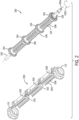
FIG. 2 is an isometric, partially exploded view of an exemplary embodiment of a topshaft assembly and a scraper assembly. -
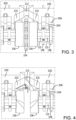
FIG. 3 is a top view of a portion of the topshaft assembly and scraper assembly of -
FIG. 2 , shown assembled together. -
FIG. 4 is top view of a portion of the scraper assembly ofFIG. 2 , with the topshaft assembly omitted. -
FIG. 5 is a perspective view of the scraper assembly ofFIG. 2 , with the topshaft assembly omitted. -
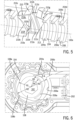
FIG. 6 is a cross-sectional side view of the topshaft assembly and scraper assembly ofFIG. 2 . -
FIG. 7 is an isometric view of a portion of the topshaft assembly ofFIG. 2 . - In the figures, like reference numerals refer to the same or similar elements.
- The drawing figures depict one or more implementations in accordance with the present concepts, by way of example only, not by way of limitations. The examples are shown in conjunction with an agricultural combine harvester, but have applicability in any similar agricultural vehicle, such as a windrower.
-
FIG. 1 shows an exemplary embodiment of anagricultural vehicle 10 in the form of a combine harvester. Thevehicle 10 generally includes achassis 26 that is supported for movement on an underlying ground surface by wheels 28 (e.g., pneumatic tires, tracked wheels, etc.), and aheader 12 that is carried by thechassis 26. - The
header 12 is configured to gather crop material from the ground, and convey it to thechassis 26 via a feeder assembly. The feeder assembly includes afeeder housing 14 in which aconveyor assembly 16 operates. Theconveyor assembly 16 includes atopshaft assembly 20 and a lower shaft that hold respective ends of an endless conveyor in the form of flexible belts or chains having paddles or the like extending between the belts or chains. The paddles drive crop material from theheader 12 to athresher 18 located in thechassis 26. The conveyor typically includes gaps between adjacent belts/chains, and between adjacent paddles, and crop material can move through these openings. The conveyor belt wraps around thetopshaft 20 with anupper belt section 24a and alower belt section 24b extending from thetopshaft assembly 20 at spaced-apart locations. Ascraper assembly 22 is located between the upper andlower belt sections -
FIG. 2 shows details of anexemplary topshaft assembly 100 andscraper assembly 200 that may be used in thevehicle 10 ofFIG. 1 , or in other vehicles or equipment. - The
topshaft assembly 100 generally comprises ashaft 102 that is mounted to thefeeder housing 14,chassis 26, or another main supporting structure byshaft bearings 112 in a conventional manner. Theshaft 102 is mounted on theshaft bearings 112 to rotate about arotation axis 102a. Along theshaft 102 are mounted one ormore sprockets 104 that are concentric to the rotation axis and, when theshaft 102 is rotated, move in arotation direction 102b about therotation axis 102a. Thesprockets 104 are conventional, and may include teeth or other drive structures to propel the conveyor belt and thereby move crop material from theheader 12 to thethresher 18. - The
scraper assembly 200 includes one ormore scraper bodies 202 located adjacent to thetopshaft assembly 100. Thescraper bodies 202 may comprise separate parts that are assembled together or adjacent to each other, or a single unitary part. Thescraper assembly 200 is mounted to thefeeder housing 14,chassis 26, or another main supporting structure, in a generally fixed position relative to theshaft bearings 112. For example, the scraper assembly may be rigidly fixed to thefeeder housing 14, or mounted to thefeeder housing 14 by flexible supports that allow a limited range of movement relative to thefeeder housing 14. In any event, thescraper assembly 200 is positioned within the two extending upper and lower sections of theconveyor belt topshaft assembly 100 during operation. - Referring now more particularly to
FIGS. 4 and5 , thescraper bodies 202 include one or moresprocket scrapers 212. Eachsprocket scraper 212 is located adjacent to an outer perimeter arespective sprocket 104, and radially aligned with therespective sprocket 104 relative to therotation axis 102a ("radially aligned" means that a radial line extending in a plane orthogonal to therotation axis 102a passes through the identified parts). Eachsprocket scraper 212 has ascraper body 212a that extends from a leadingedge 212b to atrailing edge 212c. Thetrailing edge 212c is offset from the leadingedge 212b along both therotation axis 102a and therotation direction 102b. Thus, thescraper body 212a assumes a ramp-like shape that is tilted relative to therotation axis 102a (i.e., thescraper body 212a extends in a direction that is not parallel to a plane that is orthogonal to therotation axis 102a). Thescraper body 212a may be planar, or have a curved shape, such as being formed as a segment of a helix or spiral that wraps around therotation axis 102a. - In use, crop material may occasionally move into the space between the
sprocket 104 and thesprocket scraper 212. When this happens, the adjacent crop material may be propelled by the sprocket 104 (or by other crop material or other forces) along therotation direction 102b. This crop material contacts thesprocket scraper 212, and as the crop material moves from the leadingedge 212b to thetrailing edge 212c, thesprocket scraper body 212a redirects the crop material to have a movement vector along therotation axis 102a. Or, stated differently, thesprocket scraper 212 pushes the crop material sideways along therotation axis 102a. This redirects the crop material so that less of the crop material falls on the lower stretch of the chain that is moving towards the topshaft assembly. Thus, thesprocket scraper 212 helps reduce or prevent the accumulation of crop material between the chain and thesprocket 104. - The
sprocket scraper 212 also may include a blockingwall 212d that extends along therotation axis 102a and along therotation direction 102b, with thesprocket scraper body 212a located radially between the blockingwall 212d and thesprocket 104. The blockingwall 212d forms a backstop that prevents crop material from passing radially past thesprocket scraper 212 and falling downwards onto the chain below. - In the shown examples there is a
single sprocket scraper 212 for eachsprocket 104. However,multiple sprocket scrapers 212 may be located at each sprocket. For example, asecond sprocket scraper 212 may be located below the first one and angled in the same direction or in the opposite direction. Also, asprocket scraper 212 may be formed with a chevron or inverted V shape to direct crop material in opposite directions away from the underlying chain. Other alternatives and embodiments will be apparent to persons of ordinary skill in the art in view of the present disclosure. - The
topshaft assembly 100 and/orscraper assembly 200 also may include other features to help prevent undesirable accumulations or placement of crop material. For example, referring more specifically toFIGS. 3-5 , thescraper assembly 200 may include one or more crop guides 210 that are located adjacent to one or both sides of asprocket 104, and offset from thesprocket 104 along therotation axis 102a. The crop guides 210 are configured to act as funnels or the like to direct crop material towards thesprocket 106, where the crop material can fall down, and possibly be redirected by thesprocket scraper 212 as it falls. - Each
crop guide 210 can include multiple different surfaces that help direct the crop material towards thesprocket 104. In the shown examples, eachcrop guide 210 has acrop guide wall 210a that extends along therotation direction 102b, such as along a curved path that is approximately semi-circular as viewed along therotation axis 102a. A cropguide wall step 210b extends radially from thecrop guide wall 210a towards therotation axis 102a and faces opposite therotation direction 102b, so that crop material moving in therotation direction 102b contacts thestep 210b. Thestep 210b extends from aleading end 210c to a trailingend 210d along therotation axis 102a, in a direction towards thesprocket 104. Thestep 210b also extends from theleading end 210c to the trailingend 210d forward along therotation direction 102b. - Thus, the
step 210b directs adjacent crop material at least partially along therotation axis 102a towards thesprocket 106 as the crop material moves along therotation direction 102b. - The crop
guide wall step 210b divides thecrop guide wall 210a between a leadingguide wall surface 210e and a trailingguide wall surface 210f. Because thestep 210b protrudes to face opposite therotation direction 102b, the trailingguide wall surface 210e is (at least at the location of thestep 210b) closer to therotation axis 102a than the trailingguide wall surface 210f. One or both of the leadingguide wall surface 210e and trailingguide wall surface 210f may be tapered in the radial direction away from the rotation axis at a taper angle T (seeFIG. 4 ), so as to provide another surface that directs adjacent crop material towards thesprocket 104. In the shown example, the leadingguide wall surface 210e is tapered, and the trailing guide wall surface is not tapered. One or both of the leadingguide wall surface 210e and trailingguide wall surface 210f may have a regular geometric shape, such as a conical or cylindrical shape, but other shapes (e.g., semi-spherical or complex curves) may also be used. - A
crop guide 210 may be provided on one side or both sides of asprocket 106. In addition, thecrop guide 210 may be formed in other ways. For example, the cropguide wall step 210b may be defined as a protrusion from an otherwise continuouscrop guide wall 210a (e.g., the leadingguide wall surface 210e and trailingguide wall surface 210f may have a continuous conical or cylindrical shape, with the cropguide wall step 210b being an integral protrusion from the shape). The cropguide wall step 210b also may be a separate part that is attached to thecrop guide wall 210a. Other alternatives and embodiments will be apparent to persons of ordinary skill in the art in view of the present disclosure. - The
crop guide 210 is radially aligned with an adjacent portion of thetopshaft assembly 100, and the adjacent portion also may be configured to assist with preventing or inhibiting undesirable crop accumulation. In one example, which is best shown inFIGS. 4 and7 , thetopshaft assembly 100 includes asprocket shoulder 106 that is radially aligned with thecrop guide 210. Thesprocket shoulder 106 is located adjacent to thesprocket 104, and offset from thesprocket 104 along therotation axis 102a. Thesprocket shoulder 106 may have any shape, but in this case it is generally cylindrical with the cylindrical axis collinear with therotation axis 102a. The radially outer surface of thesprocket shoulder 106 includes ashoulder step 106a, which extends radially away from the adjacent portions of thesprocket shoulder 106 and faces along therotation direction 102b to thereby push adjacent crop material as thetopshaft assembly 100 rotates in therotation direction 102b. - The
shoulder step 106a can have any shape that provides a physical obstacle to push the crop material. In the shown example, theshoulder step 106a extends along therotation axis 102a in a direction towards thesprocket 106, from aleading end 106b to a trailingend 106c. In addition, theshoulder step 106a extends from theleading end 106b to the trailingend 106c backwards along therotation direction 102b, so that the trailingend 106c trails behind theleading end 106b as thetopshaft assembly 100 rotates in therotation direction 102b. - In the shown embodiment, the
shoulder step 106a directs the adjacent crop material at least partially along therotation axis 102a towards thesprocket 106 as thetopshaft assembly 100 rotates. Theshoulder step 106a and thecrop guide 210 cooperate to funnel the crop material towards thesprocket 106 and thesprocket scraper 212, and are expected to help redistribute the crop material in a manner that reduces unwanted buildup. - In the shown example, the
shoulder step 106a is defined by arecess 106d formed in the otherwise continuously cylindrical outer perimeter wall of thesprocket shoulder 106, but in other embodiments theshoulder step 106a may be defined as a protrusion from the remainder of the outer wall. Theshoulder step 106a also may be integrally formed or added as a separate part. Asprocket shoulder 106 may be located on one side or both sides of eachsprocket 106, such as shown inFIG. 2 . It will also be appreciated that asprocket shoulder 106 having ashoulder step 106a may be provided even where acrop guide 210 is not present. Other alternatives and embodiments will be apparent to persons of ordinary skill in the art in view of the present disclosure. - The shown examples also illustrate further features to help inhibit unwanted crop accumulation. For example, the
topshaft assembly 100 may include one or morelobular rotors 108 that are distributed along therotation axis 102a and secured to rotate with theshaft 102. Eachrotor 108 extends radially away from therotation axis 102a and is offset from thesprockets 104 and sprocket shoulders 106 (if present) along therotation axis 102a. - As best shown in
FIG. 6 , the outer perimeter of eachrotor 108 has at least oneroot 108a located at a first distance R1 from therotation axis 102a, and at least onepeak 108b located at a second distance R2 from the rotation axis. The first distance R1 is the minimum distance from therotation axis 102a, and the second distance R2 is the maximum distance from therotation axis 102b. Thus, the second distance R2 is greater than the first distance R1. In this example, eachroot 108a is at the same first distance R1, and each peak 108b is at the same second distance R2, but this is not strictly required (i.e., someroots 108a and/or somepeaks 108b may be located at some distance between the first distance R1 and the second distance R2). - The outer surface of the
rotor 108 between theroots 108a and thepeaks 108b may be defined by one or more straight or curved lines as viewed along therotation axis 102a. For example, the outer perimeter may have a shape of a rounded square, as shown, or it may have other shapes, such as a star shape, a square shape, a hexagonal shape, and so on. In any event, therotor 108 includes at least one lobular region with respect to the rotation axis 102a (i.e., a region in which the distance from the outer surface to therotation axis 102a changes as a function of angle about therotation axis 102a). - The lobular regions of the
rotor 108 are expected to generate a driving force to help push adjacent crop material along therotation direction 102b, and thus help encourage breaking up and redistributing crop material that might become clumped in the region of thetopshaft assembly 100. - The
scraper assembly 200 may include structures that cooperate with thelobular rotors 108 to help remove crop material. For example, as shown inFIG. 6 , thescraper body 202 may have arotor wall 206a that is radially aligned with a respectivelobular rotor 108, and spaced from the rotation axis by a third distance R3 that is greater than the second distance R2. Thus, a gap is defined between therotor wall 206a and the lobular rotor's outer surface throughout the entire rotation of thelobular rotor 108. This gap allows the lobular regions of therotor 108 to push adjacent crop material past thescraper assembly 200 to fall down to the conveyor, pass through gaps in the conveyor, and again be pushed by the conveyor paddles towards the thresher. This arrangement is contrary to conventional concepts in which a scraper is provided closely adjacent to a cylindrical shaft in an effort to prevent any crop material from passing between the shaft and the scraper. - As indicated above, multiple
lobular rotors 108 may be distributed along therotation axis 102a. In this case, thetopshaft assembly 100 includesrotor gap sections 110 located between each pair ofrotors 108, and/or between eachrotor 108 and other structures such assprockets 104 and sprocket shoulders 106. Eachrotor gap section 110 may have a simple circular shafts shape, such as a cylindrical outer perimeter that is collinear with therotation axis 102a, but other shapes (e.g., hexagonal) are possible. The radially outermost surface of therotor gap section 110 is located at a fourth distance R4 form therotation axis 102a. The fourth distance R4 may be less than the first distance R1 (i.e., less than the minimum radial distance of thelobular rotor roots 108a), but this is not strictly required. - The
scraper assembly 200 may include features to help remove crop material at the locations of therotor gap sections 110. For example, thescraper body 202 may include one ormore rotor scrapers 204 that are radially aligned with respectiverotor gap sections 110. Eachrotor scraper 204 is spaced from the rotation axis by a fifth distance R5 that is greater than the fourth distance R4 to provide a relatively small gap to allow crop material to pass through. For example, the fifth distance R5 may be les than the first distance R1, as in the shown example. - As shown in
FIG. 4 , therotor scrapers 204 also may be closely spaced with theadjacent rotors 108 to help prevent crop material from being compressed between them. In addition, therotor scrapers 204 may be shaped such that the lead-in angle A between the top rotor scraper surface and the adjacent outer perimeter of the rotor 108 (as measured looking along therotation axis 102a) remains below 90 degrees at all rotational positions of thetopshaft assembly 100. - The
scraper assembly 200 may include still more features to help prevent unwanted accumulation of crop material. For example, the various parts of the scraper assembly may have beveled entry surfaces, such as abeveled entry 204a on each rotor scrapers 204, abeveled entry 210g on eachcrop guide 210, and abeveled entry 206b at eachrotor gap 206. Other alternatives and embodiments will be apparent to persons of ordinary skill in the art in view of the present disclosure. - The present disclosure describes a number of inventive features and/or combinations of features that may be used alone or in combination with each other or in combination with other technologies. The embodiments described herein are all exemplary, and are not intended to limit the scope of the claims. It will also be appreciated that the inventions described herein can be modified and adapted in various ways, and all such modifications and adaptations are intended to be included in the scope of this disclosure and the appended claims.
Claims (15)
- A topshaft rotary antiwrap assembly comprising:(a) a topshaft assembly (100) comprising:a shaft (102) configured for rotating about a rotation axis (102a), andone or more sprockets (104) mounted to the shaft (102) concentrically to the rotation axis (102a) to move in a rotation direction (102b) about the rotation axis; and(b) a first scraper body (202) located adjacent to the topshaft assembly (100), characterized in that the first scraper body (202) comprises:a first sprocket scraper (212) located adjacent to an outer perimeter of a first sprocket (104) of the one or more sprockets and radially aligned with the first sprocket (100) relative to the rotation axis (102a),wherein the first sprocket scraper (212) comprises a respective sprocket scraper body (212a) that extends from a respective leading edge (212b) to a respective trailing edge (212c), and wherein the trailing edge (212c) is offset from the leading edge (212b) along the rotation axis (102a) and along the rotation direction such that the sprocket scraper body (202) directs a respective adjacent portion of crop material at least partially along the rotation axis (102a) as the respective adjacent portion of crop material moves along the rotation direction (102b) from the leading edge (212b) to the trailing edge (212c).
- The topshaft rotary antiwrap assembly of claim 1, wherein the first sprocket scraper (212) further comprises a blocking wall (212d) extending along the rotation axis and along the rotation direction (102b), with the sprocket scraper body (212a) located radially between the blocking wall (212d) and the sprocket (104).
- The topshaft rotary antiwrap assembly of any one of the foregoing claims, wherein the first scraper body (212a) further comprises a first crop guide (210) located adjacent to the first sprocket (104) and offset from the first sprocket (104) along the rotation axis (102a), the first crop guide (210) comprising:a crop guide wall (210a) extending along the rotation direction; anda crop guide wall step (210b) that:extends radially from the crop guide wall (210a) towards the rotation axis (102a) to face opposite the rotation direction,extends from a respective leading end (210c) to a respective trailing end (210d) along the rotation axis (102a) in a direction towards the first sprocket (104), andextends from the respective leading end (210c) to the respective trailing end (210d) forward along the rotation direction (102b),such that the crop guide wall step (102b) directs an adjacent portion of crop material at least partially along the rotation axis (102a) towards the sprocket (104) as the respective adjacent portion of crop material moves along the rotation direction from the respective leading end (210c) to the respective trailing end (210d).
- The topshaft rotary antiwrap assembly of claim 3, wherein the crop guide wall step (102b) divides the crop guide wall (210a) between a leading guide wall surface (210e) and a trailing guide wall surface (210f), and the leading guide wall surface (210e) is tapered radially away from the rotation axis (102) in a direction extending from the respective leading end (210c) towards the respective trailing end (210d), such that the leading guide wall surface (210e) directs a respective adjacent portion of crop materially at least partially along the rotation axis towards the sprocket (104) as the respective adjacent portion of crop material moves radially away from the rotation axis (102a).
- The topshaft rotary antiwrap assembly of claim 3, wherein the topshaft assembly (100) further comprises a first sprocket shoulder (106) positioned adjacent to the first sprocket (104), and spaced radially between the crop guide wall (210a) and the rotation axis (102a), wherein the first sprocket shoulder (106) comprises a shoulder step (106a) that extends from an adjacent portion of the first sprocket shoulder (106) away from the rotation axis (102a) to face in the rotation direction (102b) and thereby direct a respective adjacent portion of crop material along the rotation direction (102b).
- The topshaft rotary antiwrap assembly of claim 5, wherein the shoulder step (106a):extends from a respective leading end (106b) to a respective trailing end (106c) along the rotation axis (102a) in a direction towards the first sprocket (104), andextends from the respective leading end (106b) to the respective trailing end (106c) backwards along the rotation direction (102b),such that the shoulder step (106a) directs the respective adjacent portion of crop material at least partially along the rotation axis (102a) towards the sprocket (104) as the respective adjacent portion of crop material moves along the rotation direction (102b) from the respective leading end (106b) to the respective trailing end (106c).
- The topshaft rotary antiwrap assembly of any one of the foregoing claims, wherein the topshaft assembly (100) further comprises one or more lobular rotors (108) mounted to rotate with the shaft (102) and extending radially away from the rotation axis (102a) and offset from the first sprocket (104) along the rotation axis (102a), wherein each lobular rotor (108) comprises a radially outer surface defined by one or more roots (108a) located at a first distance (R1) from the rotation axis (102a) and one or more peaks (108b) located at a second distance (R2) from the rotation axis (102a), wherein the second distance (R2) is greater than the first distance (R1).
- The topshaft rotary antiwrap assembly of claim 7, wherein the first scraper body (202) comprises one or more rotor walls (206a), wherein each rotor wall (206a) is radially aligned with a respective lobular rotor (108) relative to the rotation axis (102a), and is spaced from the rotation axis by a third distance (R3) that is greater than the second distance (R2), to define a gap between the rotor wall (206a) and the respective lobular rotor (108) though which a respective adjacent portion of crop material moves along the rotation direction as the lobular rotor (108) rotates in the rotation direction.
- The topshaft rotary antiwrap assembly of claim 7, wherein the topshaft assembly (100) further comprises one or more rotor gap sections (110), wherein each rotor gap section (110) is located adjacent to a respective lobular rotor (108) and offset from the respective lobular rotor along the rotation axis (102a), and wherein each rotor gap section (110) comprises a respective radially outer surface located at a fourth distance (R4) from the rotation axis, wherein the fourth distance (R4) is less than the first distance (R1).
- The topshaft rotary antiwrap assembly of claim 9, wherein the first scraper body (212a) comprises one or more rotor scrapers (204), wherein each rotor scraper (204) is radially aligned with a respective rotor gap section (110) relative to the rotation axis, and is spaced from the rotation axis by a fifth distance (R5) that is greater than the fourth distance (R4) and less than the first distance (R1).
- A feeder conveyor assembly comprising:a feeder housing (14) extending from an inlet to an outlet;a crop conveyor (16) ; anda topshaft rotary antiwrap assembly according to any one of the foregoing claims, whereinthe topshaft assembly (100) is rotatably mounted at the feeder housing outlet and partially surrounded by the crop conveyor,the one or more sprockets are in engagement with the crop conveyor,and the first scraper body is located between an upper crop conveyor section extending from the topshaft assembly at a first location, and a lower crop conveyor section extending from the topshaft assembly at a second location.
- The feeder conveyor assembly of claim 11, wherein the first scraper body (212a) further comprises a first crop guide (210) located adjacent to the first sprocket (104) and offset from the first sprocket (104) along the rotation axis (102a), the first crop guide comprising:a crop guide wall (210a) extending along the rotation direction (102b); anda crop guide wall step (210b) that:extends radially from the crop guide wall (210a) towards the rotation axis to face opposite the rotation direction,extends from a respective leading end (210c) to a respective trailing end (210d) along the rotation axis in a direction towards the first sprocket (104), andextends from the respective leading end (210c) to the respective trailing end (210d) forward along the rotation direction (102b),such that the crop guide wall step (102b) directs an adjacent portion of crop material at least partially along the rotation axis towards the sprocket (104) as the respective adjacent portion of crop material moves along the rotation direction from the respective leading end (210c) to the respective trailing end (210d).
- The feeder conveyor assembly of claim 11 or claim 12, wherein the topshaft assembly further comprises a first sprocket shoulder (106) positioned adjacent to the first sprocket (104), and spaced radially between the crop guide wall (210a) and the rotation axis (102a), wherein the first sprocket shoulder (106) comprises a shoulder step (106a) that extends from an adjacent portion of the first sprocket shoulder (106) away from the rotation axis to face in the rotation direction and thereby direct a respective adjacent portion of crop material along the rotation direction; and
wherein the shoulder step (106a):extends from a respective leading end (106b) to a respective trailing end (106c) along the rotation axis in a direction towards the first sprocket (104) to face in the rotation direction, andextends from the respective leading end (106b) to the respective trailing end (106) backwards along the rotation direction,such that the shoulder step (106a) directs the respective adjacent portion of crop material at least partially along the rotation axis (102a) towards the sprocket (104) as the respective adjacent portion of crop material moves along the rotation direction from the respective leading end (106b) to the respective trailing end (106c). - The feeder conveyor assembly of any one of claims 11-13, wherein the topshaft assembly further comprises one or more lobular rotors (108) mounted to rotate with the shaft (102) and extending radially away from the rotation axis and offset from the first sprocket (104) along the rotation axis, wherein each lobular rotor (108) comprises a radially outer surface defined by one or more roots (108a) located at a first distance R1 from the rotation axis and one or more peaks (108b) located at a second distance R2 from the rotation axis, wherein the second distance R2 is greater than the first distance R1.
- The feeder conveyor assembly of claim 14, wherein the topshaft assembly further comprises one or more rotor gap sections (110), wherein each rotor gap section (110) is located adjacent to a respective lobular rotor (108) and offset from the respective lobular rotor along the rotation axis (102a), and wherein each rotor gap section (110) comprises a respective radially outer surface located at a fourth distance R4 from the rotation axis, wherein the fourth distance R4 is less than the first distance R1.
Applications Claiming Priority (1)
| Application Number | Priority Date | Filing Date | Title |
|---|---|---|---|
| US202363545957P | 2023-10-27 | 2023-10-27 |
Publications (1)
| Publication Number | Publication Date |
|---|---|
| EP4545455A1 true EP4545455A1 (en) | 2025-04-30 |
Family
ID=93289165
Family Applications (1)
| Application Number | Title | Priority Date | Filing Date |
|---|---|---|---|
| EP24209040.5A Pending EP4545455A1 (en) | 2023-10-27 | 2024-10-25 | ROTATING COVER SHELL |
Country Status (2)
| Country | Link |
|---|---|
| US (1) | US20250134002A1 (en) |
| EP (1) | EP4545455A1 (en) |
Citations (5)
| Publication number | Priority date | Publication date | Assignee | Title |
|---|---|---|---|---|
| EP3213625A1 (en) * | 2016-03-01 | 2017-09-06 | CNH Industrial Belgium nv | Feeder apparatus for combine harvester |
| EP3219195A1 (en) * | 2016-03-14 | 2017-09-20 | CNH Industrial Belgium nv | Agricultural feeder assembly with a shielded sprocket |
| CN107223409A (en) * | 2017-06-14 | 2017-10-03 | 山东丰神农业机械有限公司 | The removal of impurities anti-wrap device of mechanical sprocket wheel |
| US20210010600A1 (en) * | 2017-11-29 | 2021-01-14 | Bernard Mccartney Limited | Seal protection mechanism |
| EP4165980A1 (en) * | 2021-10-14 | 2023-04-19 | CNH Industrial Belgium NV | Floating anti-wrap system for a conveyor top shaft |
-
2024
- 2024-10-25 EP EP24209040.5A patent/EP4545455A1/en active Pending
- 2024-10-25 US US18/926,755 patent/US20250134002A1/en active Pending
Patent Citations (5)
| Publication number | Priority date | Publication date | Assignee | Title |
|---|---|---|---|---|
| EP3213625A1 (en) * | 2016-03-01 | 2017-09-06 | CNH Industrial Belgium nv | Feeder apparatus for combine harvester |
| EP3219195A1 (en) * | 2016-03-14 | 2017-09-20 | CNH Industrial Belgium nv | Agricultural feeder assembly with a shielded sprocket |
| CN107223409A (en) * | 2017-06-14 | 2017-10-03 | 山东丰神农业机械有限公司 | The removal of impurities anti-wrap device of mechanical sprocket wheel |
| US20210010600A1 (en) * | 2017-11-29 | 2021-01-14 | Bernard Mccartney Limited | Seal protection mechanism |
| EP4165980A1 (en) * | 2021-10-14 | 2023-04-19 | CNH Industrial Belgium NV | Floating anti-wrap system for a conveyor top shaft |
Also Published As
| Publication number | Publication date |
|---|---|
| US20250134002A1 (en) | 2025-05-01 |
Similar Documents
| Publication | Publication Date | Title |
|---|---|---|
| BE1023963A9 (en) | SUPPLY UNIT WITH A PROTECTED CHAIN WHEEL FOR USE IN AGRICULTURE | |
| EP2901838B1 (en) | Seed delivery system housing and planting unit with such | |
| US6244955B1 (en) | Rotary tine conveyor for a harvesting machine | |
| US20040250523A1 (en) | Feeder roller | |
| EP3381266B1 (en) | Cogged feederhouse front drum | |
| CA2380995C (en) | Beater for a combine harvester | |
| EP3777515B1 (en) | Crop flow guide vanes | |
| CA1088763A (en) | Crop gathering apparatus | |
| EP3381267A1 (en) | Slat insert for noise/wear attenuation in a feederhouse conveyor | |
| CN102065677A (en) | Threshing section for combine | |
| US20250134002A1 (en) | Topshaft rotary antiwrap | |
| US20060242937A1 (en) | Crop take-up assembly and harvesting machine | |
| CN110447376B (en) | System for unloading harvested crop from an agricultural harvester | |
| US7578118B2 (en) | Crop conveying arrangement of a machine for harvesting crops having stalks | |
| US20260026438A1 (en) | Agricultural Harvesting Machine | |
| US6036599A (en) | Crop processing arrangement | |
| US4003191A (en) | Barrier means in a combine harvesting header | |
| BR102024022261A2 (en) | UPPER SHAFT ROTARY BEARING ANTI-WINDING ASSEMBLY | |
| US20230397539A1 (en) | Feed roll for a combine harvester | |
| US20190335665A1 (en) | System for unloading harvested crop from an agricultural harvester | |
| CA2307543A1 (en) | Tomato harvester with improved devices for feeding cut plants to the shaker | |
| US20250008878A1 (en) | A device for carrying out agricultural processing | |
| CA2525903C (en) | Replaceable feed segment for the beater of a combine harvester | |
| US20220248607A1 (en) | Containment panel liner for a farm combine | |
| JP2025079984A (en) | Pickup device and general-purpose combine equipped with pickup device |
Legal Events
| Date | Code | Title | Description |
|---|---|---|---|
| PUAI | Public reference made under article 153(3) epc to a published international application that has entered the european phase |
Free format text: ORIGINAL CODE: 0009012 |
|
| STAA | Information on the status of an ep patent application or granted ep patent |
Free format text: STATUS: THE APPLICATION HAS BEEN PUBLISHED |
|
| AK | Designated contracting states |
Kind code of ref document: A1 Designated state(s): AL AT BE BG CH CY CZ DE DK EE ES FI FR GB GR HR HU IE IS IT LI LT LU LV MC ME MK MT NL NO PL PT RO RS SE SI SK SM TR |
|
| STAA | Information on the status of an ep patent application or granted ep patent |
Free format text: STATUS: REQUEST FOR EXAMINATION WAS MADE |
|
| 17P | Request for examination filed |
Effective date: 20251030 |
|
| STAA | Information on the status of an ep patent application or granted ep patent |
Free format text: STATUS: EXAMINATION IS IN PROGRESS |