EP4545438A1 - Content container - Google Patents
Content container Download PDFInfo
- Publication number
- EP4545438A1 EP4545438A1 EP23854991.9A EP23854991A EP4545438A1 EP 4545438 A1 EP4545438 A1 EP 4545438A1 EP 23854991 A EP23854991 A EP 23854991A EP 4545438 A1 EP4545438 A1 EP 4545438A1
- Authority
- EP
- European Patent Office
- Prior art keywords
- bent portion
- discharge part
- container body
- container
- deformation suppression
- Prior art date
- Legal status (The legal status is an assumption and is not a legal conclusion. Google has not performed a legal analysis and makes no representation as to the accuracy of the status listed.)
- Pending
Links
Images



Classifications
-
- B—PERFORMING OPERATIONS; TRANSPORTING
- B65—CONVEYING; PACKING; STORING; HANDLING THIN OR FILAMENTARY MATERIAL
- B65D—CONTAINERS FOR STORAGE OR TRANSPORT OF ARTICLES OR MATERIALS, e.g. BAGS, BARRELS, BOTTLES, BOXES, CANS, CARTONS, CRATES, DRUMS, JARS, TANKS, HOPPERS, FORWARDING CONTAINERS; ACCESSORIES, CLOSURES, OR FITTINGS THEREFOR; PACKAGING ELEMENTS; PACKAGES
- B65D35/00—Pliable tubular containers adapted to be permanently or temporarily deformed to expel contents, e.g. collapsible tubes for toothpaste or other plastic or semi-liquid material; Holders therefor
- B65D35/02—Body construction
- B65D35/12—Connections between body and closure-receiving bush
-
- B—PERFORMING OPERATIONS; TRANSPORTING
- B65—CONVEYING; PACKING; STORING; HANDLING THIN OR FILAMENTARY MATERIAL
- B65D—CONTAINERS FOR STORAGE OR TRANSPORT OF ARTICLES OR MATERIALS, e.g. BAGS, BARRELS, BOTTLES, BOXES, CANS, CARTONS, CRATES, DRUMS, JARS, TANKS, HOPPERS, FORWARDING CONTAINERS; ACCESSORIES, CLOSURES, OR FITTINGS THEREFOR; PACKAGING ELEMENTS; PACKAGES
- B65D35/00—Pliable tubular containers adapted to be permanently or temporarily deformed to expel contents, e.g. collapsible tubes for toothpaste or other plastic or semi-liquid material; Holders therefor
- B65D35/02—Body construction
- B65D35/10—Body construction made by uniting or interconnecting two or more components
-
- B—PERFORMING OPERATIONS; TRANSPORTING
- B65—CONVEYING; PACKING; STORING; HANDLING THIN OR FILAMENTARY MATERIAL
- B65D—CONTAINERS FOR STORAGE OR TRANSPORT OF ARTICLES OR MATERIALS, e.g. BAGS, BARRELS, BOTTLES, BOXES, CANS, CARTONS, CRATES, DRUMS, JARS, TANKS, HOPPERS, FORWARDING CONTAINERS; ACCESSORIES, CLOSURES, OR FITTINGS THEREFOR; PACKAGING ELEMENTS; PACKAGES
- B65D35/00—Pliable tubular containers adapted to be permanently or temporarily deformed to expel contents, e.g. collapsible tubes for toothpaste or other plastic or semi-liquid material; Holders therefor
- B65D35/14—Pliable tubular containers adapted to be permanently or temporarily deformed to expel contents, e.g. collapsible tubes for toothpaste or other plastic or semi-liquid material; Holders therefor with linings or inserts
-
- B—PERFORMING OPERATIONS; TRANSPORTING
- B65—CONVEYING; PACKING; STORING; HANDLING THIN OR FILAMENTARY MATERIAL
- B65D—CONTAINERS FOR STORAGE OR TRANSPORT OF ARTICLES OR MATERIALS, e.g. BAGS, BARRELS, BOTTLES, BOXES, CANS, CARTONS, CRATES, DRUMS, JARS, TANKS, HOPPERS, FORWARDING CONTAINERS; ACCESSORIES, CLOSURES, OR FITTINGS THEREFOR; PACKAGING ELEMENTS; PACKAGES
- B65D35/00—Pliable tubular containers adapted to be permanently or temporarily deformed to expel contents, e.g. collapsible tubes for toothpaste or other plastic or semi-liquid material; Holders therefor
- B65D35/24—Pliable tubular containers adapted to be permanently or temporarily deformed to expel contents, e.g. collapsible tubes for toothpaste or other plastic or semi-liquid material; Holders therefor with auxiliary devices
- B65D35/36—Pliable tubular containers adapted to be permanently or temporarily deformed to expel contents, e.g. collapsible tubes for toothpaste or other plastic or semi-liquid material; Holders therefor with auxiliary devices for applying contents to surfaces
- B65D35/38—Nozzles
Definitions
- the present invention relates to a container, more specifically to a container that is capable of effectively suppressing a discharge part from being deformed in shape.
- a conventional tube consists of a soft tube body 11 for storing a content therein, a discharge part 12 open on top thereof to discharge the content stored in the tube body 11 therethrough, and a shoulder part 13 extending from the lower end periphery of the discharge part 12 to connect the tube body 11 and the discharge part 12. Even if not shown in FIG. 1 , a cap or nozzle having a discharge hole is coupled to the discharge part 12.
- an internal pressure of the tube body 11 increases to allow the content stored in the tube body 11 to be discharged through the discharge part 12 or the cap connected to the discharge part 12 to the outside.
- the present invention has been made in view of the above-mentioned problems occurring in the related art, and it is an object of the present invention to provide a container that is capable of effectively suppressing a discharge part from being deformed in shape.
- a container is provided according to an embodiment of the present invention.
- the container may include: a container body pressed by an external force and having an accommodation space formed therein to store a given content therein; a discharge part open on top thereof to discharge the given content therethrough if the container body is pressed; and a shoulder part extending from the outer periphery of a lower end portion of the discharge part in such a way as to connect the discharge part and the container body, wherein the shoulder part has a deformation suppression groove formed concavely on at least one area thereof in such a way as to suppress the discharge part from being deformed in shape if the container body is pressed.
- the container can allow the deformation suppression groove of the shoulder part to prevent the deformation force generated when the container body is pressed from being transferred to the discharge part, thereby effectively suppressing the discharge part from being deformed in shape.
- a container is provided according to an embodiment of the present invention.
- the container may include: a container body pressed by an external force and having an accommodation space formed therein to store a given content therein; a discharge part open on top thereof to discharge the given content therethrough if the container body is pressed; and a shoulder part extending from the outer periphery of a lower end portion of the discharge part in such a way as to connect the discharge part and the container body, wherein the shoulder part has a deformation suppression groove formed concavely on at least one area thereof in such a way as to suppress the discharge part from being deformed in shape if the container body is pressed.
- the deformation suppression groove is varied in a width of at least a given area thereof, if the container body is pressed, thereby suppressing the discharge part from being deformed in shape.
- the deformation suppression groove is spaced apart from the lower end portion of the discharge part in such a way as to surround the outer periphery of the lower end portion of the discharge part.
- the shoulder part comprises a first bent portion, a second bent portion, and a third bent portion formed sequentially from the outer periphery of the lower end portion of the discharge part in an outward direction so that the shoulder part is bent around the first to third bent portions, and the deformation suppression groove is formed by locating the second bent portion between the first bent portion and the third bent portion so that the second bent portion forms a valley.
- the deformation suppression groove comprises a first slant surface and a second slant surface located on both sides of the second bent portion, and the first slant surface extends from the second bent portion toward the first bent portion, while the second slant surface extends from the second bent portion toward the third bent portion.
- an angle between the first slant surface and the second slant surface is in the range between 60 and 120°.
- the given area of the shoulder part, on which the deformation suppression groove is formed has a thickness in the range between 0.5 and 1.0 mm.
- the deformation suppression groove has a maximum depth in the range between 0.8 and 2 mm.
- the deformation suppression groove is formed at a position distant inward by 3 to 10 mm from a connection portion between the shoulder part and the container body.
- Terms, such as the first, the second, and the like, may be used to describe various elements, but the elements should not be restricted by the terms. The terms are used to only distinguish one element from the other element.
- a first element may be named a second element without departing from the scope of the present invention.
- a second element may be named a first element.
- a term 'and/or' includes a combination of a plurality of relevant and described items or any one of a plurality of related and described items.
- one element when it is said that one element is described as being “connected” to the other element, one element may be directly connected or coupled to the other element, but it should be understood that another element may be present between the two elements.
- one portion is described as “includes” any component, further, one element may further include other components unless no specific description is suggested.
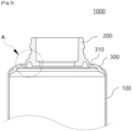
- FIG. 3 is a sectional view showing a container according to an embodiment of the present invention
- FIG. 4 is an enlarged view showing a portion 'A' of FIG. 3
- FIG. 5 is a perspective view showing the container according to the embodiment of the present invention.
- a container 1000 largely includes a container body 100, a discharge part 200, and a shoulder part 300.
- the container body 100 has an accommodation space formed at the inside thereof to store a given content.
- the container body 100 has the shape of a tube open on top thereof and sealed on bottom thereof, but without being limited thereto, the container body 100 may have various shapes reduced in volume when pressed, such as soft bottles, tottles, and the like.
- the container body 100 has at least a portion made of a soft material. If the outer periphery of the container body 100 is pressed by an external force applied by a user, the container body 100 is deformed (that is, compressed) in shape to allow the content stored therein to be discharged to the outside through the discharge part 200.
- the content is, for example, a liquid or gel cosmetic content, a drug, a quasi-drug, etc.
- the content may be lotion, milk lotion, moisture lotion, nutrition lotion, skin lotion, skin softer, skin toner, astringent, massage cream, nutrition cream, whitening essence, tone-up cream, sunblock, sun cream, sun milk, BB cream, base, foundation, CC cream, concealer, blusher, shade, eyeshadow, eyebrow, eye cream, primer, etc.
- the content may not be limited thereto, and therefore, the content may include various types of materials that are stored in the container body 100 and thus discharged to the outside when the container body 100 is pressed.
- the discharge part 200 is disposed on top of the container body 100 in such a way as to communicate with the container body 100 and serves to discharge the content to the outside through an open top thereof.
- the discharge part 200 is coupled to a cap or nozzle having a discharge hole, a pump, or the like.
- the discharge part 200 has at least one coupling portion formed on the outer peripheral surface thereof.
- the coupling portion is a screw thread, a coupling protrusion, a coupling groove, or the like, but without being limited thereto, a variety of coupling portions may be formed on the discharge part 200.
- the shoulder part 300 extends downward from the outer periphery of the lower end portion of the discharge part 200 at a given inclination in an outward direction in such a way as to connect the container body 100 and the discharge part 200. At least a portion of the upper end portion of the container body 100 is sealed with the should part 300.
- the shoulder part 300 has a given thickness and is made of a synthetic resin harder than the container body 100.
- the lower end portion of the shoulder part 300 is coupled to the upper end portion of the container body 100 by means of various methods such as thermal adhesion, ultrasonic adhesion, adhesion using an adhesive, double injection molding, and the like.
- some of the container body 100, the discharge part 200, and the shoulder part 300 may be formed unitarily with each other by means of injection molding.
- the discharge part 200 and the shoulder part 300 may be formed unitarily with each other by means of injection molding, and next, they are coupled to the upper end portion of the container body 100 by means of adhesion.
- the shoulder part 300 has a deformation suppression groove 310 as an inward concave formed on at least a given area thereof.
- the deformation suppression groove 310 serves to suppress the discharge part 200 from being deformed in shape when the container body 100 is pressed to discharge the content therefrom.
- at least a given area of the deformation suppression groove 310 is contracted or expanded to allow the width of the deformation suppression groove 310 to be changed in size, so that the deformation force caused by the pressing of the container body 100 is prevented from being transferred to the discharge part 200 through the shoulder part 300, thereby suppressing the discharge part 200 from being deformed in shape.
- a maximum depth of the deformation suppression groove 310 is in the range between 0.8 and 2 mm, and a portion of the shoulder part 300, on which the deformation suppression groove 310 is formed, has a thickness in the range between 0.5 and 1.0 mm.
- the deformation suppression groove 310 is formed spaced apart from a connection portion between the discharge part 200 and/or the shoulder part 300 and the container body 100 by a given distance.
- the deformation suppression groove 310 has the shape of a circle and is spaced apart from the lower end portion of the discharge part 200 in such a way as to surround the outer periphery of the lower end portion of the discharge part 200.
- the deformation suppression groove 310 is formed at a position distant inward by 3 to 10 mm from the connection portion between the shoulder part 300 and the container body 100.
- the shoulder part 300 includes a first bent portion 320, a second bent portion 330, and a third bent portion 330.
- the first bent portion 320, the second bent portion 330, and the third bent portion 330 of the shoulder part 300 are formed sequentially from the outer periphery of the lower end portion of the discharge part 200, and as the shoulder part 300 is bent around the first to third bent portions 320 to 340 at given curvatures, the deformation suppression groove 310 is formed.
- the deformation suppression groove 310 is formed by locating the second bent portion 330 between the first bent portion 320 and the third bent portion 340 so that the second bent portion 330 forms a valley (that is, a point with a maximum depth).
- a first slant surface 311 and a second slant surface 312 are formed on the inside of the deformation suppression groove 310.
- the first slant surface 311 and the second slant surface 312 are located on both sides of the second bent portion 330 in such a way as to extend to the first bent portion 320 and the third bent portion 340.
- the deformation suppression groove 310 has the sectional shape of "V". In a state where the container body 100 is not pressed, an angle between the first slant surface 311 and the second slant surface 312 is in the range between 60 and 120°.
- the container 1000 as shown in FIGs. 3 to 5 is just exemplary in shape, and therefore, the container 1000 may have various shapes according to embodiments of the present invention. According to the embodiments of the present invention, further, the container 100 may have additional parts such as a cap, a nozzle, and the like as well as the container body 100, the discharge part 200, and the shoulder part 300 as mentioned above.
- the shoulder part having the deformation suppression groove and the discharge part according to the present invention were made (See FIG. 6a ), and a shoulder part having a plurality of reinforcing ribs and a discharge part were made (See FIG. 6b ).
- the reinforcing ribs served to support the outer periphery of the discharge part and suppress the discharge part from being deformed in shape.
- the container with the shoulder part and the discharge part according to the present invention was made (in a first embodiment of the present invention), and a container with the shoulder part having the plurality of reinforcing ribs and the discharge part was made (in a first comparison example). After that, deformation experiments for both containers were carried out.
- caps were coupled to the discharge parts of the containers in the first embodiment of the present invention and the first comparison example, and if the container bodies of the containers were pressed, the width of the deformation suppression groove corresponding to the pressed position of the container body of the container in the first embodiment of the present invention was varied to allow the shoulder part to be substantially spaced apart from the cap (See FIG. 7a ). However, a gap between the shoulder part and the cap of the container in the first comparison example was small (See FIG. 7b ).
- Container body 200 Discharge part 300: Shoulder part 310: Deformation suppression groove 311: First slant surface 312: Second slant surface 320: First bent portion 330: Second bent portion 340: Third bent portion 1000: Container
Landscapes
- Engineering & Computer Science (AREA)
- Mechanical Engineering (AREA)
- Containers Having Bodies Formed In One Piece (AREA)
- Containers And Packaging Bodies Having A Special Means To Remove Contents (AREA)
- Tubes (AREA)
Abstract
Description
- The present invention relates to a container, more specifically to a container that is capable of effectively suppressing a discharge part from being deformed in shape.
- As shown in
FIG. 1 , a conventional tube consists of asoft tube body 11 for storing a content therein, adischarge part 12 open on top thereof to discharge the content stored in thetube body 11 therethrough, and ashoulder part 13 extending from the lower end periphery of thedischarge part 12 to connect thetube body 11 and thedischarge part 12. Even if not shown inFIG. 1 , a cap or nozzle having a discharge hole is coupled to thedischarge part 12. - If the outer periphery of the
tube body 11 of the tube is pressed by a user, an internal pressure of thetube body 11 increases to allow the content stored in thetube body 11 to be discharged through thedischarge part 12 or the cap connected to thedischarge part 12 to the outside. - However, as shown in
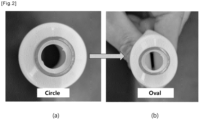
FIG. 2 , as thetube body 11 of the tube is pressed, the force generated from the pressing is transferred to thedischarge part 12 through theshoulder part 13 so that thedischarge part 12 becomes deformed to an oval shape from a circular shape, thereby causing the content to leak between thedischarge part 12 and the cap coupled to thedischarge part 12. - Therefore, there is a need to develop a new container capable of effectively suppressing a discharge part from being deformed in shape.
- Accordingly, the present invention has been made in view of the above-mentioned problems occurring in the related art, and it is an object of the present invention to provide a container that is capable of effectively suppressing a discharge part from being deformed in shape.
- The technical problems to be achieved through the present invention are not limited as mentioned above, and other technical problems not mentioned herein will be obviously understood by one of ordinary skill in the art through the following description.
- A container is provided according to an embodiment of the present invention. The container may include: a container body pressed by an external force and having an accommodation space formed therein to store a given content therein; a discharge part open on top thereof to discharge the given content therethrough if the container body is pressed; and a shoulder part extending from the outer periphery of a lower end portion of the discharge part in such a way as to connect the discharge part and the container body, wherein the shoulder part has a deformation suppression groove formed concavely on at least one area thereof in such a way as to suppress the discharge part from being deformed in shape if the container body is pressed.
- According to the present invention, the container can allow the deformation suppression groove of the shoulder part to prevent the deformation force generated when the container body is pressed from being transferred to the discharge part, thereby effectively suppressing the discharge part from being deformed in shape.
- To allow the drawings as will be mentioned in the description of the present invention to be more sufficiently understood, the brief description of the drawings may be provided.
-
FIG. 1 is a sectional view showing a conventional tube, andFIG. 2 shows photographs of the deformation of a discharge part when a tube body of the conventional tube is pressed. -
FIG. 3 is a sectional view showing a container according to an embodiment of the present invention. -
FIG. 4 is an enlarged view showing a portion 'A' ofFIG. 3 . -
FIG. 5 is a perspective view showing the container according to the embodiment of the present invention. -
FIG. 6 shows photographs of a shoulder part with a deformation suppression groove according to the embodiment of the present invention and a shoulder part with reinforcing ribs formed on the inside thereof. -
FIGs. 7 and8 are photographs showing comparison experimental results, when container bodies are pressed, between the container (in a first embodiment) according to the embodiment of the present invention and the container (in a first comparison example) having the shoulder part with the reinforcing ribs formed on the inside thereof. - A container is provided according to an embodiment of the present invention. The container may include: a container body pressed by an external force and having an accommodation space formed therein to store a given content therein; a discharge part open on top thereof to discharge the given content therethrough if the container body is pressed; and a shoulder part extending from the outer periphery of a lower end portion of the discharge part in such a way as to connect the discharge part and the container body, wherein the shoulder part has a deformation suppression groove formed concavely on at least one area thereof in such a way as to suppress the discharge part from being deformed in shape if the container body is pressed.
- Further, the deformation suppression groove is varied in a width of at least a given area thereof, if the container body is pressed, thereby suppressing the discharge part from being deformed in shape.
- Furthermore, the deformation suppression groove is spaced apart from the lower end portion of the discharge part in such a way as to surround the outer periphery of the lower end portion of the discharge part.
- Besides, the shoulder part comprises a first bent portion, a second bent portion, and a third bent portion formed sequentially from the outer periphery of the lower end portion of the discharge part in an outward direction so that the shoulder part is bent around the first to third bent portions, and the deformation suppression groove is formed by locating the second bent portion between the first bent portion and the third bent portion so that the second bent portion forms a valley.
- Further, the deformation suppression groove comprises a first slant surface and a second slant surface located on both sides of the second bent portion, and the first slant surface extends from the second bent portion toward the first bent portion, while the second slant surface extends from the second bent portion toward the third bent portion.
- Furthermore, in a state where the container body is not pressed, an angle between the first slant surface and the second slant surface is in the range between 60 and 120°.
- Besides, the given area of the shoulder part, on which the deformation suppression groove is formed, has a thickness in the range between 0.5 and 1.0 mm.
- Moreover, the deformation suppression groove has a maximum depth in the range between 0.8 and 2 mm.
- Further, the deformation suppression groove is formed at a position distant inward by 3 to 10 mm from a connection portion between the shoulder part and the container body.
- Hereinafter, example embodiments will be described with reference to the accompanying drawings. In addition, a device of the present invention and a method for using the device will be explained in detail with reference to the attached drawings. In the drawings, the same reference numerals or symbols are parts or components performing the same functions. Further, top, bottom, left and right directions as will be described below are determined with reference to the drawings, and accordingly, the scope of the present invention is not necessarily restricted to the corresponding directions.
- Terms, such as the first, the second, and the like, may be used to describe various elements, but the elements should not be restricted by the terms. The terms are used to only distinguish one element from the other element. For example, a first element may be named a second element without departing from the scope of the present invention. Likewise, a second element may be named a first element. A term 'and/or' includes a combination of a plurality of relevant and described items or any one of a plurality of related and described items.
- Terms used in this application are used to only describe specific exemplary embodiments and are not intended to restrict the present invention. An expression referencing a singular value additionally refers to a corresponding expression of the plural number, unless explicitly limited otherwise by the context. In this application, terms, such as "comprise", "include", or 'have", are intended to designate those characteristics, numbers, steps, operations, elements, or parts which are described in the specification, or any combination of them that exist, and it should be understood that they do not preclude the possibility of the existence or possible addition of one or more additional characteristics, numbers, steps, operations, elements, or parts, or combinations thereof.
- In the description, when it is said that one element is described as being "connected" to the other element, one element may be directly connected or coupled to the other element, but it should be understood that another element may be present between the two elements. When it is said that one portion is described as "includes" any component, further, one element may further include other components unless no specific description is suggested.
-
FIG. 3 is a sectional view showing a container according to an embodiment of the present invention,FIG. 4 is an enlarged view showing a portion 'A' ofFIG. 3 , andFIG. 5 is a perspective view showing the container according to the embodiment of the present invention. - Referring to
FIGs. 3 to 5 , acontainer 1000 according to an embodiment of the present invention largely includes acontainer body 100, adischarge part 200, and ashoulder part 300. - The
container body 100 has an accommodation space formed at the inside thereof to store a given content. Thecontainer body 100 has the shape of a tube open on top thereof and sealed on bottom thereof, but without being limited thereto, thecontainer body 100 may have various shapes reduced in volume when pressed, such as soft bottles, tottles, and the like. - According to the embodiment of the present invention, the
container body 100 has at least a portion made of a soft material. If the outer periphery of thecontainer body 100 is pressed by an external force applied by a user, thecontainer body 100 is deformed (that is, compressed) in shape to allow the content stored therein to be discharged to the outside through thedischarge part 200. - In this case, the content is, for example, a liquid or gel cosmetic content, a drug, a quasi-drug, etc. For example, the content may be lotion, milk lotion, moisture lotion, nutrition lotion, skin lotion, skin softer, skin toner, astringent, massage cream, nutrition cream, whitening essence, tone-up cream, sunblock, sun cream, sun milk, BB cream, base, foundation, CC cream, concealer, blusher, shade, eyeshadow, eyebrow, eye cream, primer, etc. However, the content may not be limited thereto, and therefore, the content may include various types of materials that are stored in the
container body 100 and thus discharged to the outside when thecontainer body 100 is pressed. - The
discharge part 200 is disposed on top of thecontainer body 100 in such a way as to communicate with thecontainer body 100 and serves to discharge the content to the outside through an open top thereof. - According to the embodiment of the present invention, the
discharge part 200 is coupled to a cap or nozzle having a discharge hole, a pump, or the like. To do this, thedischarge part 200 has at least one coupling portion formed on the outer peripheral surface thereof. For example, the coupling portion is a screw thread, a coupling protrusion, a coupling groove, or the like, but without being limited thereto, a variety of coupling portions may be formed on thedischarge part 200. - The
shoulder part 300 extends downward from the outer periphery of the lower end portion of thedischarge part 200 at a given inclination in an outward direction in such a way as to connect thecontainer body 100 and thedischarge part 200. At least a portion of the upper end portion of thecontainer body 100 is sealed with the shouldpart 300. - The
shoulder part 300 has a given thickness and is made of a synthetic resin harder than thecontainer body 100. - According to the embodiment of the present invention, the lower end portion of the
shoulder part 300 is coupled to the upper end portion of thecontainer body 100 by means of various methods such as thermal adhesion, ultrasonic adhesion, adhesion using an adhesive, double injection molding, and the like. - According to the embodiment of the present invention, some of the
container body 100, thedischarge part 200, and theshoulder part 300 may be formed unitarily with each other by means of injection molding. For example, thedischarge part 200 and theshoulder part 300 may be formed unitarily with each other by means of injection molding, and next, they are coupled to the upper end portion of thecontainer body 100 by means of adhesion. - The
shoulder part 300 has adeformation suppression groove 310 as an inward concave formed on at least a given area thereof. Thedeformation suppression groove 310 serves to suppress thedischarge part 200 from being deformed in shape when thecontainer body 100 is pressed to discharge the content therefrom. When thecontainer body 100 is pressed, in detail, at least a given area of thedeformation suppression groove 310 is contracted or expanded to allow the width of thedeformation suppression groove 310 to be changed in size, so that the deformation force caused by the pressing of thecontainer body 100 is prevented from being transferred to thedischarge part 200 through theshoulder part 300, thereby suppressing thedischarge part 200 from being deformed in shape. According to the embodiment of the present invention, a maximum depth of thedeformation suppression groove 310 is in the range between 0.8 and 2 mm, and a portion of theshoulder part 300, on which thedeformation suppression groove 310 is formed, has a thickness in the range between 0.5 and 1.0 mm. - The
deformation suppression groove 310 is formed spaced apart from a connection portion between thedischarge part 200 and/or theshoulder part 300 and thecontainer body 100 by a given distance. For example, thedeformation suppression groove 310 has the shape of a circle and is spaced apart from the lower end portion of thedischarge part 200 in such a way as to surround the outer periphery of the lower end portion of thedischarge part 200. According to the embodiment of the present invention, thedeformation suppression groove 310 is formed at a position distant inward by 3 to 10 mm from the connection portion between theshoulder part 300 and thecontainer body 100. - To form the
deformation suppression groove 310, theshoulder part 300 includes a firstbent portion 320, a secondbent portion 330, and a thirdbent portion 330. The firstbent portion 320, the secondbent portion 330, and the thirdbent portion 330 of theshoulder part 300 are formed sequentially from the outer periphery of the lower end portion of thedischarge part 200, and as theshoulder part 300 is bent around the first to thirdbent portions 320 to 340 at given curvatures, thedeformation suppression groove 310 is formed. For example, thedeformation suppression groove 310 is formed by locating the secondbent portion 330 between the firstbent portion 320 and the thirdbent portion 340 so that the secondbent portion 330 forms a valley (that is, a point with a maximum depth). - According to the embodiment of the present invention, a
first slant surface 311 and asecond slant surface 312 are formed on the inside of thedeformation suppression groove 310. For example, thefirst slant surface 311 and thesecond slant surface 312 are located on both sides of the secondbent portion 330 in such a way as to extend to the firstbent portion 320 and the thirdbent portion 340. As a result, thedeformation suppression groove 310 has the sectional shape of "V". In a state where thecontainer body 100 is not pressed, an angle between thefirst slant surface 311 and thesecond slant surface 312 is in the range between 60 and 120°. - The
container 1000 as shown inFIGs. 3 to 5 is just exemplary in shape, and therefore, thecontainer 1000 may have various shapes according to embodiments of the present invention. According to the embodiments of the present invention, further, thecontainer 100 may have additional parts such as a cap, a nozzle, and the like as well as thecontainer body 100, thedischarge part 200, and theshoulder part 300 as mentioned above. - As shown in
FIG. 6 , the shoulder part having the deformation suppression groove and the discharge part according to the present invention were made (SeeFIG. 6a ), and a shoulder part having a plurality of reinforcing ribs and a discharge part were made (SeeFIG. 6b ). In this case, the reinforcing ribs served to support the outer periphery of the discharge part and suppress the discharge part from being deformed in shape. - Next, the container with the shoulder part and the discharge part according to the present invention was made (in a first embodiment of the present invention), and a container with the shoulder part having the plurality of reinforcing ribs and the discharge part was made (in a first comparison example). After that, deformation experiments for both containers were carried out.
- Referring first to
FIG. 7 , caps were coupled to the discharge parts of the containers in the first embodiment of the present invention and the first comparison example, and if the container bodies of the containers were pressed, the width of the deformation suppression groove corresponding to the pressed position of the container body of the container in the first embodiment of the present invention was varied to allow the shoulder part to be substantially spaced apart from the cap (SeeFIG. 7a ). However, a gap between the shoulder part and the cap of the container in the first comparison example was small (SeeFIG. 7b ). - Referring next to
FIG. 8 and Table 1, if the container bodies of the containers in the first embodiment of the present invention and the first comparison example were pressed, the discharge part of the container in the first embodiment of the present invention was kept in the shape of a circle (SeeFIG. 8a ), but the discharge part of the container in the first comparison example was deformed to the shape of an oval (SeeFIG. 8b ).Table 1 Maximum width of discharge part prior to pressing the container body Maximum width of discharge part after the container body is pressed Degree of deformation First embodiment of the present invention 15.78 mm 15.99 mm 0.21 mm First comparison example 15.75 mm 16.40 mm 0.65 mm - It can be appreciated from Table 1 that in the case of the embodiment where the deformation suppression groove is formed on the shoulder part, the force (deformation force) generated when the container body is pressed changes the width of the deformation suppression groove, without being transferred to the discharge part, so that the discharge part is effectively prevented from being deformed in shape.
- As mentioned above, the preferred embodiment of the present invention has been disclosed in the specification and drawings. Therefore, persons skilled in the relevant art can appreciate that many modifications and variations are possible in light of the above teachings. It is therefore intended that the scope of the invention be limited not by this detailed description, but rather by the claims appended hereto.
100: Container body 200: Discharge part 300: Shoulder part 310: Deformation suppression groove 311: First slant surface 312: Second slant surface 320: First bent portion 330: Second bent portion 340: Third bent portion 1000: Container
Claims (9)
- A container comprising:a container body pressed by an external force and having an accommodation space formed therein to store a given content therein;a discharge part open on top thereof to discharge the given content therethrough if the container body is pressed; anda shoulder part extending from the outer periphery of a lower end portion of the discharge part in such a way as to connect the discharge part and the container body,wherein the shoulder part has a deformation suppression groove formed concavely on at least one area thereof in such a way as to suppress the discharge part from being deformed in shape if the container body is pressed.
- The container according to claim 1, wherein the deformation suppression groove is varied in a width of at least a given area thereof, if the container body is pressed, to thus suppress the discharge part from being deformed in shape.
- The container according to claim 2, wherein the deformation suppression groove is spaced apart from the lower end portion of the discharge part in such a way as to surround the outer periphery of the lower end portion of the discharge part.
- The container according to claim 3, wherein the shoulder part comprises a first bent portion, a second bent portion, and a third bent portion formed sequentially from the outer periphery of the lower end portion of the discharge part in an outward direction so that the shoulder part is bent around the first to third bent portions, and the deformation suppression groove is formed by locating the second bent portion between the first bent portion and the third bent portion so that the second bent portion forms a valley.
- The container according to claim 4, wherein the deformation suppression groove comprises a first slant surface and a second slant surface on both sides of the second bent portion, and the first slant surface extends from the second bent portion toward the first bent portion, while the second slant surface extends from the second bent portion toward the third bent portion.
- The container according to claim 5, wherein in a state where the container body is not pressed, an angle between the first slant surface and the second slant surface is in the range between 60 and 120°.
- The container according to claim 2, wherein the given area of the shoulder part, on which the deformation suppression groove is formed, has a thickness in the range between 0.5 and 1.0 mm.
- The container according to claim 2, wherein the deformation suppression groove has a maximum depth in the range between 0.8 and 2 mm.
- The container according to claim 2, wherein the deformation suppression groove is formed at a position distant inward by 3 to 10 mm from a connection portion between the shoulder part and the container body.
Applications Claiming Priority (2)
| Application Number | Priority Date | Filing Date | Title |
|---|---|---|---|
| KR1020220102701A KR102733208B1 (en) | 2022-08-17 | 2022-08-17 | Container |
| PCT/KR2023/007743 WO2024039020A1 (en) | 2022-08-17 | 2023-06-07 | Content container |
Publications (2)
| Publication Number | Publication Date |
|---|---|
| EP4545438A1 true EP4545438A1 (en) | 2025-04-30 |
| EP4545438A4 EP4545438A4 (en) | 2025-11-05 |
Family
ID=89942052
Family Applications (1)
| Application Number | Title | Priority Date | Filing Date |
|---|---|---|---|
| EP23854991.9A Pending EP4545438A4 (en) | 2022-08-17 | 2023-06-07 | CONTENTS CONTAINER |
Country Status (6)
| Country | Link |
|---|---|
| US (1) | US20260070707A1 (en) |
| EP (1) | EP4545438A4 (en) |
| JP (1) | JP2025525794A (en) |
| KR (1) | KR102733208B1 (en) |
| CN (1) | CN119630592A (en) |
| WO (1) | WO2024039020A1 (en) |
Family Cites Families (10)
| Publication number | Priority date | Publication date | Assignee | Title |
|---|---|---|---|---|
| JPS6171471U (en) * | 1984-10-17 | 1986-05-15 | ||
| JPH08282691A (en) * | 1995-04-19 | 1996-10-29 | Toppan Printing Co Ltd | Inverted tube container |
| EP1995179B1 (en) * | 1999-06-30 | 2011-03-23 | Yoshino Kogyosho Co., Ltd. | Synthetic resin made tube container |
| US6846443B1 (en) * | 2000-03-16 | 2005-01-25 | Pechiney Plastic Packaging, Inc | Method for forming an improved container |
| JP5937802B2 (en) | 2011-10-11 | 2016-06-22 | 武内プレス工業株式会社 | Tube container |
| JP2020007018A (en) * | 2018-07-10 | 2020-01-16 | 大日本印刷株式会社 | Tube container and tube container with cap |
| JP7293830B2 (en) * | 2019-04-11 | 2023-06-20 | 凸版印刷株式会社 | tube container |
| JP2021113076A (en) * | 2020-01-20 | 2021-08-05 | 凸版印刷株式会社 | Tube container |
| JP7714879B2 (en) * | 2021-01-20 | 2025-07-30 | Toppanホールディングス株式会社 | Tube container |
| US20230249880A1 (en) * | 2020-07-10 | 2023-08-10 | Aisapack Holding Sa | Thermoformed tube head, tube and manufacturing method |
-
2022
- 2022-08-17 KR KR1020220102701A patent/KR102733208B1/en active Active
-
2023
- 2023-06-07 EP EP23854991.9A patent/EP4545438A4/en active Pending
- 2023-06-07 US US19/102,311 patent/US20260070707A1/en active Pending
- 2023-06-07 JP JP2025504731A patent/JP2025525794A/en active Pending
- 2023-06-07 WO PCT/KR2023/007743 patent/WO2024039020A1/en not_active Ceased
- 2023-06-07 CN CN202380057379.7A patent/CN119630592A/en active Pending
Also Published As
| Publication number | Publication date |
|---|---|
| EP4545438A4 (en) | 2025-11-05 |
| CN119630592A (en) | 2025-03-14 |
| WO2024039020A1 (en) | 2024-02-22 |
| KR20240024558A (en) | 2024-02-26 |
| JP2025525794A (en) | 2025-08-07 |
| US20260070707A1 (en) | 2026-03-12 |
| KR102733208B1 (en) | 2024-11-25 |
Similar Documents
| Publication | Publication Date | Title |
|---|---|---|
| EP3521199B1 (en) | Discharge container | |
| US11820561B2 (en) | Contents container | |
| US9788633B2 (en) | Extrusion type cosmetic container | |
| JP2001253458A (en) | Pump and accommodation device provided with the pump | |
| JP7260258B2 (en) | Container with lid, multiple containers, and method of assembling container with lid | |
| US12528097B2 (en) | Pump assembly | |
| US20230204085A1 (en) | Elastic member and pump assembly including the same | |
| US11925947B2 (en) | Fluid dispenser | |
| US20250100744A1 (en) | Container with tubular skirt | |
| US20260070707A1 (en) | Content container | |
| US20250289630A1 (en) | Dropper cap | |
| US12378039B2 (en) | Container | |
| EP3225562B1 (en) | Synthetic resin bottle | |
| KR20210132846A (en) | Airtight container | |
| US20250222475A1 (en) | Contents container of which head part is raised and lowered by rotation | |
| KR20230001423U (en) | Discharge-type cap and bottel having the same | |
| JP2018154390A (en) | Double aerosol container | |
| KR101911923B1 (en) | Cosmetic container | |
| EP4450420A1 (en) | Content container | |
| KR20250038996A (en) | Content discharging container | |
| KR102808426B1 (en) | Cosmetic container | |
| EP4556394A1 (en) | Contents container | |
| KR200311646Y1 (en) | A container cap with pump | |
| KR20240099560A (en) | Container | |
| KR200270814Y1 (en) | Unitary Type Dispensing Valve Closure |
Legal Events
| Date | Code | Title | Description |
|---|---|---|---|
| STAA | Information on the status of an ep patent application or granted ep patent |
Free format text: STATUS: THE INTERNATIONAL PUBLICATION HAS BEEN MADE |
|
| PUAI | Public reference made under article 153(3) epc to a published international application that has entered the european phase |
Free format text: ORIGINAL CODE: 0009012 |
|
| STAA | Information on the status of an ep patent application or granted ep patent |
Free format text: STATUS: REQUEST FOR EXAMINATION WAS MADE |
|
| 17P | Request for examination filed |
Effective date: 20250124 |
|
| AK | Designated contracting states |
Kind code of ref document: A1 Designated state(s): AL AT BE BG CH CY CZ DE DK EE ES FI FR GB GR HR HU IE IS IT LI LT LU LV MC ME MK MT NL NO PL PT RO RS SE SI SK SM TR |
|
| A4 | Supplementary search report drawn up and despatched |
Effective date: 20251002 |
|
| RIC1 | Information provided on ipc code assigned before grant |
Ipc: B65D 35/10 20060101AFI20250926BHEP Ipc: B65D 35/38 20060101ALI20250926BHEP Ipc: B65D 35/14 20060101ALI20250926BHEP |
|
| DAV | Request for validation of the european patent (deleted) | ||
| DAX | Request for extension of the european patent (deleted) | ||
| STAA | Information on the status of an ep patent application or granted ep patent |
Free format text: STATUS: EXAMINATION IS IN PROGRESS |