EP4545405A1 - Aircraft cargo door actuation system - Google Patents
Aircraft cargo door actuation system Download PDFInfo
- Publication number
- EP4545405A1 EP4545405A1 EP24205097.9A EP24205097A EP4545405A1 EP 4545405 A1 EP4545405 A1 EP 4545405A1 EP 24205097 A EP24205097 A EP 24205097A EP 4545405 A1 EP4545405 A1 EP 4545405A1
- Authority
- EP
- European Patent Office
- Prior art keywords
- cargo door
- actuator
- rod
- open position
- actuator rod
- Prior art date
- Legal status (The legal status is an assumption and is not a legal conclusion. Google has not performed a legal analysis and makes no representation as to the accuracy of the status listed.)
- Pending
Links
Images






Classifications
-
- B—PERFORMING OPERATIONS; TRANSPORTING
- B64—AIRCRAFT; AVIATION; COSMONAUTICS
- B64C—AEROPLANES; HELICOPTERS
- B64C1/00—Fuselages; Constructional features common to fuselages, wings, stabilising surfaces or the like
- B64C1/14—Windows; Doors; Hatch covers or access panels; Surrounding frame structures; Canopies; Windscreens accessories therefor, e.g. pressure sensors, water deflectors, hinges, seals, handles, latches, windscreen wipers
- B64C1/1407—Doors; surrounding frames
- B64C1/1415—Cargo doors, e.g. incorporating ramps
-
- B—PERFORMING OPERATIONS; TRANSPORTING
- B64—AIRCRAFT; AVIATION; COSMONAUTICS
- B64C—AEROPLANES; HELICOPTERS
- B64C1/00—Fuselages; Constructional features common to fuselages, wings, stabilising surfaces or the like
- B64C1/14—Windows; Doors; Hatch covers or access panels; Surrounding frame structures; Canopies; Windscreens accessories therefor, e.g. pressure sensors, water deflectors, hinges, seals, handles, latches, windscreen wipers
-
- E—FIXED CONSTRUCTIONS
- E05—LOCKS; KEYS; WINDOW OR DOOR FITTINGS; SAFES
- E05F—DEVICES FOR MOVING WINGS INTO OPEN OR CLOSED POSITION; CHECKS FOR WINGS; WING FITTINGS NOT OTHERWISE PROVIDED FOR, CONCERNED WITH THE FUNCTIONING OF THE WING
- E05F15/00—Power-operated mechanisms for wings
- E05F15/60—Power-operated mechanisms for wings using electrical actuators
-
- E—FIXED CONSTRUCTIONS
- E05—LOCKS; KEYS; WINDOW OR DOOR FITTINGS; SAFES
- E05Y—INDEXING SCHEME ASSOCIATED WITH SUBCLASSES E05D AND E05F, RELATING TO CONSTRUCTION ELEMENTS, ELECTRIC CONTROL, POWER SUPPLY, POWER SIGNAL OR TRANSMISSION, USER INTERFACES, MOUNTING OR COUPLING, DETAILS, ACCESSORIES, AUXILIARY OPERATIONS NOT OTHERWISE PROVIDED FOR, APPLICATION THEREOF
- E05Y2900/00—Application of doors, windows, wings or fittings thereof
- E05Y2900/50—Application of doors, windows, wings or fittings thereof for vehicles
- E05Y2900/502—Application of doors, windows, wings or fittings thereof for vehicles for aircraft or spacecraft
Definitions
- the present invention relates to an actuation system for a cargo door of an aircraft, a method of opening a cargo door of an aircraft, and an aircraft with a cargo door and associated actuation system.
- US6457675B1 discloses a door actuation system for an outwardly opening cargo door.
- the cargo door is operable to open to two positions: a canopy position in which the cargo door is generally outright thereby providing an overhang over the door opening, and a fully opened position in which the cargo door is substantially vertical to maximize the cargo opening.
- a first aspect of the invention provides an aircraft comprising: a body with an opening into a cargo bay; a cargo door configured to rotate about a hinge line; a first actuator coupled to the cargo door at a first location, wherein the first actuator is configured to outwardly rotate the cargo door from a closed position, in which it covers the opening, to a first open position; a first rod coupling feature in the body configured to couple a first end of an actuator rod to the body; and a second rod coupling feature positioned at a second location in the cargo door, wherein the second rod coupling feature is configured to couple a second end of the actuator rod to the cargo door at the second location, and the second location is positioned further from the hinge line than the first location.
- the aircraft further comprises a footrest which can be stepped on when the cargo door is in the first open position.
- the footrest can be moved relative to the body between an extended configuration and a retracted configuration.
- the first rod coupling feature comprises one or more fastener holes in the body.
- the second rod coupling feature comprises one or more fastener holes in the cargo door.
- the aircraft further comprises an actuator rod configured to outwardly rotate the cargo door from the first open position to a second open position by increasing a distance between first and second ends of the actuator rod, wherein the actuator rod has a first end configured to be coupled to the first rod coupling feature, and a second end configured to be coupled to the second rod coupling feature.
- a further aspect of the invention provides an actuation system for a cargo door of an aircraft, wherein the cargo door covers an opening into a cargo bay when it is in a closed position and the cargo door is configured to rotate about a hinge line
- the actuation system comprising: a first actuator configured to outwardly rotate the cargo door from the closed position to a first open position, wherein the first actuator is coupled to the cargo door at a first location; and an actuator rod configured to outwardly rotate the cargo door from the first open position to a second open position by increasing a distance between first and second ends of the actuator rod, wherein the actuator rod is coupled to the cargo door at a second location and the second location is positioned further from the hinge line than the first location.
- the first actuator is configured to receive power from a first power source which can be used by the first actuator to rotate the cargo door
- the actuator rod is configured to receive power from a second power source which can be used by the actuator rod to rotate the cargo door.
- the cargo door rotates by more than 30 degrees or more than 40 degrees from the first open position to the second open position.
- a total rotation from the closed position to the second open position is more than 100 degrees or more than 110 degrees.
- a further aspect of the invention provides a method of opening a cargo door of an aircraft, the aircraft comprising a body with an opening into a cargo bay, and a cargo door which covers the opening when it is in a closed position, the method comprising: outwardly rotating the cargo door with a first actuator from the closed position to a first open position; then installing an actuator rod by coupling a first end of an actuator rod to the body and coupling a second end of the actuator rod to the cargo door in the first open position; and then outwardly rotating the cargo door with the actuator rod from the first open position to a second open position by increasing a distance between the first and second ends of the actuator rod.
- the method further comprises disconnecting the first actuator from the cargo door after it has been used to outwardly rotate the cargo door to the first open position and before rotating the cargo door with the actuator rod.
- the first actuator and the actuator rod receive power from different and independent power sources.
- the first actuator receives power from a first power source and the actuator rod receives power from a second power source.
- the cargo door rotates by more than 40 degrees from the closed position to the first open position.
- a first actuator which is carried by the aircraft in flight, is configured to outwardly rotate the cargo door.
- the aircraft also has rod coupling features, such as fastener holes, which are carried by the aircraft in flight. The rod coupling features can be used to couple an actuator rod to the aircraft if the cargo door needs to be opened more widely, for instance after an emergency landing.
- a freighter aircraft 1 shown in Figure 1 comprises a fuselage 2 and a pair of wings 3. As shown in Figure 2 , the fuselage 2 has an opening 10 into a cargo bay 11. A cargo door 13 covers the opening 10 when it is in the closed position shown in Figure 1 .
- An actuation system is configured to open the cargo door, enabling cargo 20 (shown in Figures 2 and 3 ) to be loaded into, or unloaded from, the cargo bay 11.
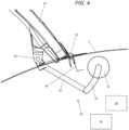
- the actuation system comprises a first actuator 30 shown in Figure 4 .
- the first actuator 30 is configured to outwardly rotate the cargo door 13 from the closed position of Figure 1 , in which it covers the opening 10, to a first open position shown in Figures 2-4 .
- the cargo door 13 is configured to rotate about a hinge pin which defines a hinge line 15 shown in Figure 4 .
- the first open position of Figures 2-4 is conventionally known as a "canopy position", providing an overhang over the opening 10.
- the term “canopy position” will be used below to refer to the first open position.
- the cargo door rotates by more than 40 degrees, more than 50 degrees or more than 60 degrees from the closed position to the first open position.
- the cargo door may rotate by about 70 degrees between the closed position and the canopy position.
- the first actuator 30 comprises a rotary actuator 31 shown in Figure 4 .
- the rotary actuator 31 is mounted to the fuselage 2 and has a crank arm 32 pivotally connected to a link 33 which is pivotally coupled to the cargo door 13 by a pivot pin 34 at a first location near the hinge line 15.
- the rotary actuator 31 is configured to receive electrical power from a power source 35 shown schematically in Figure 4 .
- the electrical power is used by the first actuator 30 to rotate the cargo door 13.
- the power source 35 may be carried by the aircraft or not carried by the aircraft (for instance it may be a ground power unit).
- the rotary actuator 31 rotates the crank arm 32, which causes the cargo door 13 to rotate about the hinge line 15.
- the first actuator 30 is controlled by a first control signal from a control unit 36.
- the control unit 36 may be carried by the aircraft or not carried by the aircraft (for instance it may be part of a ground power unit).
- the cargo 20 can be loaded or unloaded by specialised equipment which does not clash with the cargo door 13 when the cargo door 13 is in the canopy position.
- the aircraft may land at an airport without such specialised equipment, where a fork-lift must be used instead.
- specialised equipment where a fork-lift must be used instead.
- the cargo door 13 is in the canopy position, there is a risk of the fork-lift clashing with the cargo door 13.
- a solution to avoid such a clash would be to use a larger actuator capable of opening the cargo door further beyond the canopy position, such as the actuator disclosed in US6457675B1 .
- Disadvantages of such a solution are that such an actuator is likely to be heavier, and it may clash with a lintel 36 shown in Figure 4 .
- the following method is used to open the cargo door 13 beyond the canopy position, without requiring modification of the first actuator 30 or removal of the lintel 36.
- the cargo door 13 is rotated outwardly by the first actuator 30 from the closed position to the canopy position.
- a gas-stay rod 50 shown in Figure 7 is installed by an operator 51 at the forward edge of the cargo door.
- the aircraft comprises a footrest 35 which can be stepped on by the operator 51 when the cargo door 13 is in the canopy position, as shown in Figure 2 .
- the footrest 35 can be moved relative to the fuselage between an extended configuration shown in Figure 2 , and a retracted configuration.
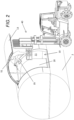
- the footrest 35 may have a Z-shaped profile shown in Figures 5 and 6 , with three parts 35a, 35b, 35c which can be folded about hinges.
- Figure 5 the footrest 35 is in an extended (unfolded) configuration
- Figure 6 the footrest 35 is in a retracted (folded) configuration.
- the footrest 35 may be mounted on a sliding bearing so it can be slid away from the opening 10 when not in use.
- the operator 51 may bring a separate footrest to the aircraft which they mount to the fuselage 2.
- the operator 51 may be attached to the cargo door and the fork-lift 40 by harness lines shown in Figure 3 , to provide a further safety feature.
- the gas-stay rod 50 is a passive device designed to support half the weight of the cargo door 13 without actively driving rotation of the cargo door. In other words, the gas-stay rod 50 is not an actuator.
- the gas-stay rod 50 is installed by coupling a first end of the gas-stay rod to the fuselage 2 and coupling a second end of the gas-stay rod to the cargo door 13. The gas stay rod 50 is in equilibrium with the weight of the cargo door.
- an actuator rod 60 shown in Figure 7 is installed by coupling a first (lower) end of the actuator rod 60 to the fuselage 2 and coupling a second (upper) end of the actuator rod 60 to the aft edge of the cargo door 13.
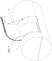
- a first rod coupling feature (in this case a set of four fastener holes 70 shown in Figures 8 and 9 ) is provided in the fuselage 2, at the aft edge of the opening 10.
- the fastener holes 70 are configured to couple the first (lower) end of the actuator rod 60 to the fuselage 2, as shown in Figure 11 .
- the actuator rod 60 comprises a rod body 61a shown in Figure 11 , and a first bracket 62 with a clevis 63 and clevis pin 64.
- the first end of the actuator rod is coupled to the fuselage 2 by attaching the bracket 62 to the fuselage as shown in Figure 10 with fasteners 65 which pass through the bracket 62 and the fastener holes 70; then coupling the rod body 61a to the bracket 62 by passing the clevis pin 64 through the clevis 63 and the lower end of the rod body 61a as shown in Figure 11 .
- a similar arrangement may be provided in the fuselage, at the forward edge of the opening 10, to couple the first (lower) end of the gas-stay rod 50 to the fuselage 2.
- bracket 62 may be replaced by an alternative bracket which provides a ball-and-socket joint rather than a pin-joint.
- fastener holes 70 may be sealed by temporary inserts (such as HI-LITE TM pins, blind rivets or grommets) which are removed before inserting the fasteners 65.
- temporary inserts such as HI-LITE TM pins, blind rivets or grommets
- the first rod coupling feature is a set of fastener holes 70.
- the first rod coupling feature may take a different form, for instance it may comprise a reinforced socket into which the first (lower) end of the actuator rod 60 is plugged to couple the actuator rod 60 to the fuselage 2.
- a second rod coupling feature (in this case a set of four fastener holes 80 shown in Figures 8 and 12 ) is provided at the aft edge of the cargo door 13.
- the fastener holes 80 are configured to couple the second (upper) end of the actuator rod 60 to the cargo door 13, as shown in Figure 14 .
- the actuator rod 60 comprises an actuator arm 61b shown in Figure 14 , and a second bracket 82 with a clevis 83 and clevis pin 84.
- the second (upper) end of the actuator rod is coupled to the cargo door 13 by attaching the bracket 82 to the cargo door as shown in Figure 13 with fasteners 85 which pass through the bracket 82 and the fastener holes 80; then coupling the actuator arm 61b to the bracket 82 by passing the clevis pin 84 through the clevis 83 and the upper end of the actuator arm 61b as shown in Figure 14 .
- a similar arrangement may be provided in the forward edge of the cargo door, to couple the second (upper) end of the gas-stay rod 50 to the cargo door.
- bracket 82 may be replaced by an alternative bracket which provides a ball-and-socket joint rather than a pin-joint.
- fastener holes 80 may be sealed by temporary inserts (such as HI-LITE TM pins, blind rivets or grommets) which are removed before inserting the fasteners 85.
- temporary inserts such as HI-LITE TM pins, blind rivets or grommets
- the second rod coupling feature is a set of fastener holes 80.
- the second rod coupling feature may take a different form, for instance it may comprise a reinforced socket into which the second (upper) end of the actuator rod 60 is plugged to couple the actuator rod 60 to the cargo door.
- the actuator rod 60 is at the forward edge of the cargo door and the gas-stay rod 50 is at the aft edge. This arrangement may be reversed if needed.
- the second rod coupling feature i.e. the set of fastener holes 80
- the second rod coupling feature is positioned at a second location 33 which is further from the hinge line 15 than the first location of the pivot pin 34. This enables the fastener holes 80 to be accessed easily by the operator 51.
- the first actuator 30 is disconnected from the cargo door 13 by the operator 51.
- the first actuator 30 may be disconnected by removing the pivot pin 34 to disconnect the link 33 from the cargo door 13, or by disconnecting the link 33 from the crank arm 32, or by disconnecting the crank arm 32 from the rotary actuator 31.
- the two rods 50, 60 now support the full weight of the cargo door.
- the first actuator 30 may not need to be disconnected from the cargo door 13.
- a ground power unit (GPU) 90 is coupled to the actuator rod 60.
- the GPU 90 is then operated to supply electrical power to the actuator rod 60, causing the actuator rod 60 to outwardly rotate the cargo door 13 further from the canopy position to a second open position shown in Figures 7 and 15 , in which the cargo door is generally upright.
- the actuator rod 60 may be controlled by a second control signal from a second control unit 91.
- the second control unit 91 may be carried by the aircraft or not carried by the aircraft (in this case it is part of the GPU 90).
- the cargo door 13 In the second open position, the cargo door 13 is lifted sufficiently high to avoid any risk of clash with the fork-lift 40, or a larger fork-lift with a higher mast which may be required to unload the cargo.
- the cargo door rotates by more than 30 degrees or more than 40 degrees from the first open position to the second open position.
- a total rotation from the closed position to the second open position is more than 100 degrees or more than 110 degrees.
- the cargo door may rotate by about 53 degrees between the canopy position and the second open position, so the total rotation is about 123 degrees.
- the actuator rod 60 may have a large enough stroke length to open the cargo door 13 further beyond the second position of Figure 15 so that the cargo bay can be accessed from above by a crane.
- the first actuator 30 is unable to rotate the cargo door to the second open position because the crank arm 32 or the link 33 may clash with a lintel 36 shown in Figure 4 .
- the first actuator 30 is actively decoupled from the cargo door before operation of the actuator rod 60, to avoid such a clash.
- the actuator rod 60 is a linear actuator which rotates the cargo door by increasing a distance between the first and second ends of the actuator rod 60.
- the actuator rod 60 is a screw jack which is powered by electrical power from the GPU 90.
- the actuator rod 60 may be a hydraulic jack driven by a hydraulic power source, or it may be manually powered by the operator 51.
- the distance of the second location 33 from the hinge line 15 is chosen based on the length of the actuator rod 60 and the power that can be delivered by the GPU 90.
- the actuators 30, 60 are configured to receive power from different and independent power sources 35, 90, although in other embodiments they may receive power from the same power source.
- the actuators 30, 60 are configured to be controlled independently of each other. That is, the first actuator 30 is configured to be controlled by a first control signal and the actuator rod 60 is configured to be controlled by a different second control signal.
- the first and second control signals may be generated by different control units 36, 91; or by a common control unit.
- the actuator rod 60 is typically powered by a power source (for instance the GPU 90) not carried by the aircraft. This is beneficial since after an emergency landing, the aircraft may have a damaged landing gear and it may be recommended not to use aircraft systems. Also, it makes it unnecessary to design connections in the aircraft to deliver power to the actuator rod 60 - such connections adding complexity and weight.
- a power source for instance the GPU 90
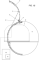
- FIG 16 to 22 show an alternative embodiment in which the fastener holes 70, 80 are in different locations. All other aspects are the same as in the previous embodiment, so will not be described again.
- the fastener holes 70 are provided in the forward face of a door frame at the aft edge of the opening 10. In the case of Figure 17 , the fastener holes 70 are provided in the outer face of the fuselage 2 at the aft edge of the opening 10.
- the fastener holes 80 are provided in the inner face of the cargo door.
- the fastener holes 80 are provided in the outer edge of the cargo door 13.
- Figures 20-22 shows the coupling arrangement at the upper end of the gas-stay rod 50 at the forward edge of the cargo door. A similar arrangement may be provided for the actuator rod 60 at the aft edge of the cargo door.
Landscapes
- Engineering & Computer Science (AREA)
- Mechanical Engineering (AREA)
- Aviation & Aerospace Engineering (AREA)
- Power-Operated Mechanisms For Wings (AREA)
Abstract
A method of opening a cargo door of an aircraft, the aircraft comprising a body with an opening into a cargo bay, and a cargo door which covers the opening when it is in a closed position. A cargo door is outwardly rotated with a first actuator from the closed position to a first open position. Then an actuator rod is installed by coupling a first end of an actuator rod to the body and coupling a second end of the actuator rod to the cargo door in the first open position. Then the cargo door is outwardly rotated with the actuator rod from the first open position to a second open position by increasing a distance between the first and second ends of the actuator rod.
Description
- The present invention relates to an actuation system for a cargo door of an aircraft, a method of opening a cargo door of an aircraft, and an aircraft with a cargo door and associated actuation system.
-
US6457675B1 discloses a door actuation system for an outwardly opening cargo door. The cargo door is operable to open to two positions: a canopy position in which the cargo door is generally outright thereby providing an overhang over the door opening, and a fully opened position in which the cargo door is substantially vertical to maximize the cargo opening. - A first aspect of the invention provides an aircraft comprising: a body with an opening into a cargo bay; a cargo door configured to rotate about a hinge line; a first actuator coupled to the cargo door at a first location, wherein the first actuator is configured to outwardly rotate the cargo door from a closed position, in which it covers the opening, to a first open position; a first rod coupling feature in the body configured to couple a first end of an actuator rod to the body; and a second rod coupling feature positioned at a second location in the cargo door, wherein the second rod coupling feature is configured to couple a second end of the actuator rod to the cargo door at the second location, and the second location is positioned further from the hinge line than the first location.
- Optionally the aircraft further comprises a footrest which can be stepped on when the cargo door is in the first open position.
- Optionally the footrest can be moved relative to the body between an extended configuration and a retracted configuration.
- Optionally the first rod coupling feature comprises one or more fastener holes in the body.
- Optionally the second rod coupling feature comprises one or more fastener holes in the cargo door.
- Optionally the aircraft further comprises an actuator rod configured to outwardly rotate the cargo door from the first open position to a second open position by increasing a distance between first and second ends of the actuator rod, wherein the actuator rod has a first end configured to be coupled to the first rod coupling feature, and a second end configured to be coupled to the second rod coupling feature.
- A further aspect of the invention provides an actuation system for a cargo door of an aircraft, wherein the cargo door covers an opening into a cargo bay when it is in a closed position and the cargo door is configured to rotate about a hinge line, the actuation system comprising: a first actuator configured to outwardly rotate the cargo door from the closed position to a first open position, wherein the first actuator is coupled to the cargo door at a first location; and an actuator rod configured to outwardly rotate the cargo door from the first open position to a second open position by increasing a distance between first and second ends of the actuator rod, wherein the actuator rod is coupled to the cargo door at a second location and the second location is positioned further from the hinge line than the first location.
- Optionally the first actuator is configured to receive power from a first power source which can be used by the first actuator to rotate the cargo door, and the actuator rod is configured to receive power from a second power source which can be used by the actuator rod to rotate the cargo door.
- Optionally the first actuator is configured to outwardly rotate the cargo door by more than 40 degrees, more than 50 degrees or more than 60 degrees from the closed position to the first open position.
- Optionally the cargo door rotates by more than 30 degrees or more than 40 degrees from the first open position to the second open position.
- Optionally a total rotation from the closed position to the second open position is more than 100 degrees or more than 110 degrees.
- A further aspect of the invention provides a method of opening a cargo door of an aircraft, the aircraft comprising a body with an opening into a cargo bay, and a cargo door which covers the opening when it is in a closed position, the method comprising: outwardly rotating the cargo door with a first actuator from the closed position to a first open position; then installing an actuator rod by coupling a first end of an actuator rod to the body and coupling a second end of the actuator rod to the cargo door in the first open position; and then outwardly rotating the cargo door with the actuator rod from the first open position to a second open position by increasing a distance between the first and second ends of the actuator rod.
- Optionally the method further comprises disconnecting the first actuator from the cargo door after it has been used to outwardly rotate the cargo door to the first open position and before rotating the cargo door with the actuator rod.
- Optionally the first actuator and the actuator rod receive power from different and independent power sources.
- Optionally the first actuator receives power from a first power source and the actuator rod receives power from a second power source.
- Optionally the first power source is carried by the aircraft and the second power source is not carried by the aircraft.
- Optionally the cargo door rotates by more than 40 degrees from the closed position to the first open position.
- Embodiments of the invention will now be described with reference to the accompanying drawings, in which:
-
Figure 1 is a plan view of a freighter aircraft; -
Figure 2 is an isometric view showing the cargo door in a canopy position; -
Figure 3 is a sectional view showing the cargo door in the canopy position; -
Figure 4 shows the first actuator in detail; -
Figure 5 shows a footrest in an unfolded configuration; -
Figure 6 shows the footrest in a folded configuration; -
Figure 7 shows the cargo door in a second open position, with the gas-stay and actuation rods shown; -
Figure 8 shows the cargo door in the second open position, with the gas-stay and actuation rods omitted so the fastener holes can be seen; -
Figure 9 shows fastener holes in the door frame of the fuselage; -
Figure 10 shows a first bracket attached to the fuselage; -
Figure 11 shows the interface between the first end of the actuator rod and the fuselage; -
Figure 12 shows fastener holes in the inside face of the cargo door; -
Figure 13 shows a second bracket attached to the cargo door; -
Figure 14 shows the interface between the second end of the actuator rod and the cargo door; -
Figure 15 shows the cargo door in the second open position, with cargo partially removed; -
Figure 16 shows the cargo door in the second open position, with the gas-stay and actuation rods attached differently compared withFigure 7 ; -
Figure 17 shows fastener holes in the fuselage; -
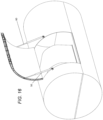
Figure 18 shows a first bracket attached to the fuselage; -
Figure 19 shows the interface between the first end of the actuator rod and the fuselage; -
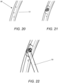
Figure 20 shows fastener holes in the edge of the cargo door; -
Figure 21 shows a second bracket attached to the cargo door; and -
Figure 22 shows the interface between the second end of the actuator rod and the cargo door. - The embodiments below facilitate wide opening of an aircraft cargo door whilst also reducing the strain placed on the rest of the aircraft. A first actuator, which is carried by the aircraft in flight, is configured to outwardly rotate the cargo door. The aircraft also has rod coupling features, such as fastener holes, which are carried by the aircraft in flight. The rod coupling features can be used to couple an actuator rod to the aircraft if the cargo door needs to be opened more widely, for instance after an emergency landing.
- A
freighter aircraft 1 shown inFigure 1 comprises afuselage 2 and a pair ofwings 3. As shown inFigure 2 , thefuselage 2 has anopening 10 into acargo bay 11. Acargo door 13 covers theopening 10 when it is in the closed position shown inFigure 1 . - An actuation system is configured to open the cargo door, enabling cargo 20 (shown in
Figures 2 and3 ) to be loaded into, or unloaded from, thecargo bay 11. - The actuation system comprises a
first actuator 30 shown inFigure 4 . Thefirst actuator 30 is configured to outwardly rotate thecargo door 13 from the closed position ofFigure 1 , in which it covers theopening 10, to a first open position shown inFigures 2-4 . Thecargo door 13 is configured to rotate about a hinge pin which defines ahinge line 15 shown inFigure 4 . - The first open position of
Figures 2-4 is conventionally known as a "canopy position", providing an overhang over the opening 10. The term "canopy position" will be used below to refer to the first open position. Typically the cargo door rotates by more than 40 degrees, more than 50 degrees or more than 60 degrees from the closed position to the first open position. By way of example, the cargo door may rotate by about 70 degrees between the closed position and the canopy position. - The
first actuator 30 comprises arotary actuator 31 shown inFigure 4 . Therotary actuator 31 is mounted to thefuselage 2 and has acrank arm 32 pivotally connected to alink 33 which is pivotally coupled to thecargo door 13 by apivot pin 34 at a first location near thehinge line 15. Therotary actuator 31 is configured to receive electrical power from apower source 35 shown schematically inFigure 4 . The electrical power is used by thefirst actuator 30 to rotate thecargo door 13. Thepower source 35 may be carried by the aircraft or not carried by the aircraft (for instance it may be a ground power unit). Therotary actuator 31 rotates thecrank arm 32, which causes thecargo door 13 to rotate about thehinge line 15. - The
first actuator 30 is controlled by a first control signal from acontrol unit 36. Thecontrol unit 36 may be carried by the aircraft or not carried by the aircraft (for instance it may be part of a ground power unit). - During normal operation of the
aircraft 1, thecargo 20 can be loaded or unloaded by specialised equipment which does not clash with thecargo door 13 when thecargo door 13 is in the canopy position. In an emergency the aircraft may land at an airport without such specialised equipment, where a fork-lift must be used instead. When thecargo door 13 is in the canopy position, there is a risk of the fork-lift clashing with thecargo door 13. - A solution to avoid such a clash would be to use a larger actuator capable of opening the cargo door further beyond the canopy position, such as the actuator disclosed in
US6457675B1 . Disadvantages of such a solution are that such an actuator is likely to be heavier, and it may clash with alintel 36 shown inFigure 4 . - The following method is used to open the
cargo door 13 beyond the canopy position, without requiring modification of thefirst actuator 30 or removal of thelintel 36. - In a first step, the
cargo door 13 is rotated outwardly by thefirst actuator 30 from the closed position to the canopy position. - Next, a gas-
stay rod 50 shown inFigure 7 is installed by anoperator 51 at the forward edge of the cargo door. - During the installation process, the
operator 51 is lifted to the required position by a fork-lift 40 shown inFigures 2 and3 . - The aircraft comprises a
footrest 35 which can be stepped on by theoperator 51 when thecargo door 13 is in the canopy position, as shown inFigure 2 . - The
footrest 35 can be moved relative to the fuselage between an extended configuration shown inFigure 2 , and a retracted configuration. By way of example, thefootrest 35 may have a Z-shaped profile shown inFigures 5 and 6 , with threeparts Figure 5 thefootrest 35 is in an extended (unfolded) configuration and inFigure 6 thefootrest 35 is in a retracted (folded) configuration. Thefootrest 35 may be mounted on a sliding bearing so it can be slid away from theopening 10 when not in use. - In an alternative embodiment, instead of providing a
footrest 35 permanently carried by the aircraft, theoperator 51 may bring a separate footrest to the aircraft which they mount to thefuselage 2. - Optionally the
operator 51 may be attached to the cargo door and the fork-lift 40 by harness lines shown inFigure 3 , to provide a further safety feature. - The gas-
stay rod 50 is a passive device designed to support half the weight of thecargo door 13 without actively driving rotation of the cargo door. In other words, the gas-stay rod 50 is not an actuator. The gas-stay rod 50 is installed by coupling a first end of the gas-stay rod to thefuselage 2 and coupling a second end of the gas-stay rod to thecargo door 13. Thegas stay rod 50 is in equilibrium with the weight of the cargo door. - In the next step, an
actuator rod 60 shown inFigure 7 is installed by coupling a first (lower) end of theactuator rod 60 to thefuselage 2 and coupling a second (upper) end of theactuator rod 60 to the aft edge of thecargo door 13. - A first rod coupling feature (in this case a set of four
fastener holes 70 shown inFigures 8 and9 ) is provided in thefuselage 2, at the aft edge of theopening 10. The fastener holes 70 are configured to couple the first (lower) end of theactuator rod 60 to thefuselage 2, as shown inFigure 11 . - The
actuator rod 60 comprises arod body 61a shown inFigure 11 , and afirst bracket 62 with aclevis 63 andclevis pin 64. The first end of the actuator rod is coupled to thefuselage 2 by attaching thebracket 62 to the fuselage as shown inFigure 10 withfasteners 65 which pass through thebracket 62 and the fastener holes 70; then coupling therod body 61a to thebracket 62 by passing theclevis pin 64 through theclevis 63 and the lower end of therod body 61a as shown inFigure 11 . - A similar arrangement may be provided in the fuselage, at the forward edge of the
opening 10, to couple the first (lower) end of the gas-stay rod 50 to thefuselage 2. - Optionally the
bracket 62 may be replaced by an alternative bracket which provides a ball-and-socket joint rather than a pin-joint. - Optionally the fastener holes 70 may be sealed by temporary inserts (such as HI-LITE™ pins, blind rivets or grommets) which are removed before inserting the
fasteners 65. - In this example, the first rod coupling feature is a set of fastener holes 70. In other examples, the first rod coupling feature may take a different form, for instance it may comprise a reinforced socket into which the first (lower) end of the
actuator rod 60 is plugged to couple theactuator rod 60 to thefuselage 2. - A second rod coupling feature (in this case a set of four
fastener holes 80 shown inFigures 8 and12 ) is provided at the aft edge of thecargo door 13. The fastener holes 80 are configured to couple the second (upper) end of theactuator rod 60 to thecargo door 13, as shown inFigure 14 . Theactuator rod 60 comprises anactuator arm 61b shown inFigure 14 , and asecond bracket 82 with aclevis 83 andclevis pin 84. The second (upper) end of the actuator rod is coupled to thecargo door 13 by attaching thebracket 82 to the cargo door as shown inFigure 13 withfasteners 85 which pass through thebracket 82 and the fastener holes 80; then coupling theactuator arm 61b to thebracket 82 by passing theclevis pin 84 through theclevis 83 and the upper end of theactuator arm 61b as shown inFigure 14 . - A similar arrangement may be provided in the forward edge of the cargo door, to couple the second (upper) end of the gas-
stay rod 50 to the cargo door. - Optionally the
bracket 82 may be replaced by an alternative bracket which provides a ball-and-socket joint rather than a pin-joint. - Optionally the fastener holes 80 may be sealed by temporary inserts (such as HI-LITE™ pins, blind rivets or grommets) which are removed before inserting the
fasteners 85. - In this example, the second rod coupling feature is a set of fastener holes 80. In other examples, the second rod coupling feature may take a different form, for instance it may comprise a reinforced socket into which the second (upper) end of the
actuator rod 60 is plugged to couple theactuator rod 60 to the cargo door. - The symmetrical arrangement shown in
Figure 7 , with a pair ofrods cargo door 13 at its forward and aft edges, avoids twisting of thecargo door 13. - In this example the
actuator rod 60 is at the forward edge of the cargo door and the gas-stay rod 50 is at the aft edge. This arrangement may be reversed if needed. - As shown in
Figure 15 , the second rod coupling feature (i.e. the set of fastener holes 80) is positioned at asecond location 33 which is further from thehinge line 15 than the first location of thepivot pin 34. This enables the fastener holes 80 to be accessed easily by theoperator 51. - Next the
first actuator 30 is disconnected from thecargo door 13 by theoperator 51. Thefirst actuator 30 may be disconnected by removing thepivot pin 34 to disconnect thelink 33 from thecargo door 13, or by disconnecting thelink 33 from thecrank arm 32, or by disconnecting thecrank arm 32 from therotary actuator 31. The tworods - In other embodiments, the
first actuator 30 may not need to be disconnected from thecargo door 13. - In the next step, a ground power unit (GPU) 90, schematically shown in
Figure 15 , is coupled to theactuator rod 60. - The
GPU 90 is then operated to supply electrical power to theactuator rod 60, causing theactuator rod 60 to outwardly rotate thecargo door 13 further from the canopy position to a second open position shown inFigures 7 and15 , in which the cargo door is generally upright. - The
actuator rod 60 may be controlled by a second control signal from asecond control unit 91. Thesecond control unit 91 may be carried by the aircraft or not carried by the aircraft (in this case it is part of the GPU 90). - In the second open position, the
cargo door 13 is lifted sufficiently high to avoid any risk of clash with the fork-lift 40, or a larger fork-lift with a higher mast which may be required to unload the cargo. Typically the cargo door rotates by more than 30 degrees or more than 40 degrees from the first open position to the second open position. - Typically a total rotation from the closed position to the second open position is more than 100 degrees or more than 110 degrees.
- By way of example, the cargo door may rotate by about 53 degrees between the canopy position and the second open position, so the total rotation is about 123 degrees.
- Optionally the
actuator rod 60 may have a large enough stroke length to open thecargo door 13 further beyond the second position ofFigure 15 so that the cargo bay can be accessed from above by a crane. - The
first actuator 30 is unable to rotate the cargo door to the second open position because thecrank arm 32 or thelink 33 may clash with alintel 36 shown inFigure 4 . In this example, thefirst actuator 30 is actively decoupled from the cargo door before operation of theactuator rod 60, to avoid such a clash. - The
actuator rod 60 is a linear actuator which rotates the cargo door by increasing a distance between the first and second ends of theactuator rod 60. In this example theactuator rod 60 is a screw jack which is powered by electrical power from theGPU 90. In other examples theactuator rod 60 may be a hydraulic jack driven by a hydraulic power source, or it may be manually powered by theoperator 51. - The distance of the
second location 33 from thehinge line 15 is chosen based on the length of theactuator rod 60 and the power that can be delivered by theGPU 90. - The
actuators independent power sources - The
actuators first actuator 30 is configured to be controlled by a first control signal and theactuator rod 60 is configured to be controlled by a different second control signal. The first and second control signals may be generated bydifferent control units - The
actuator rod 60 is typically powered by a power source (for instance the GPU 90) not carried by the aircraft. This is beneficial since after an emergency landing, the aircraft may have a damaged landing gear and it may be recommended not to use aircraft systems. Also, it makes it unnecessary to design connections in the aircraft to deliver power to the actuator rod 60 - such connections adding complexity and weight. - Neither the gas-
stay rod 50 nor theactuator rod 60 are carried by the aircraft in flight. This minimizes the weight of the aircraft in flight. After an emergency landing, theoperator 51 travels to the airport with therods -
Figure 16 to 22 show an alternative embodiment in which the fastener holes 70, 80 are in different locations. All other aspects are the same as in the previous embodiment, so will not be described again. - In the case of
Figure 9 , the fastener holes 70 are provided in the forward face of a door frame at the aft edge of theopening 10. In the case ofFigure 17 , the fastener holes 70 are provided in the outer face of thefuselage 2 at the aft edge of theopening 10. - In the case of
Figure 12 , the fastener holes 80 are provided in the inner face of the cargo door. In the case ofFigure 20 , the fastener holes 80 are provided in the outer edge of thecargo door 13. Note thatFigures 20-22 shows the coupling arrangement at the upper end of the gas-stay rod 50 at the forward edge of the cargo door. A similar arrangement may be provided for theactuator rod 60 at the aft edge of the cargo door. - Note that in the example of
Figure 20 there are only twofastener holes 80, rather than four in the case ofFigure 12 . The number of holes may vary from 1-10 depending on the weight of the cargo door, the wind conditions and availability of the standard equipment in the market. - Where the word 'or' appears this is to be construed to mean 'and/or' such that items referred to are not necessarily mutually exclusive and may be used in any appropriate combination.
- Although the invention has been described above with reference to one or more preferred embodiments, it will be appreciated that various changes or modifications may be made without departing from the scope of the invention as defined in the appended claims.
Claims (15)
- An aircraft comprising: a body with an opening into a cargo bay; a cargo door configured to rotate about a hinge line; a first actuator coupled to the cargo door at a first location, wherein the first actuator is configured to outwardly rotate the cargo door from a closed position, in which it covers the opening, to a first open position; a first rod coupling feature in the body configured to couple a first end of an actuator rod to the body; and a second rod coupling feature positioned at a second location in the cargo door, wherein the second rod coupling feature is configured to couple a second end of the actuator rod to the cargo door at the second location, and the second location is positioned further from the hinge line than the first location.
- An aircraft according to claim 1, further comprising a footrest which can be stepped on when the cargo door is in the first open position.
- An aircraft according to claim 2, wherein the footrest can be moved relative to the body between an extended configuration and a retracted configuration.
- An aircraft according to any preceding claim, wherein the first rod coupling feature comprises one or more fastener holes in the body.
- An aircraft according to any preceding claim, wherein the second rod coupling feature comprises one or more fastener holes in the cargo door.
- An aircraft according to any preceding claim, further comprising an actuator rod configured to outwardly rotate the cargo door from the first open position to a second open position by increasing a distance between first and second ends of the actuator rod, wherein the actuator rod has a first end configured to be coupled to the first rod coupling feature, and a second end configured to be coupled to the second rod coupling feature.
- An aircraft according to any preceding claim, wherein the first actuator is configured to outwardly rotate the cargo door by more than 40 degrees from the closed position to the first open position.
- An actuation system for a cargo door of an aircraft, wherein the cargo door covers an opening into a cargo bay when it is in a closed position and the cargo door is configured to rotate about a hinge line, the actuation system comprising: a first actuator configured to outwardly rotate the cargo door from the closed position to a first open position, wherein the first actuator is coupled to the cargo door at a first location; and an actuator rod configured to outwardly rotate the cargo door from the first open position to a second open position by increasing a distance between first and second ends of the actuator rod, wherein the actuator rod is coupled to the cargo door at a second location and the second location is positioned further from the hinge line than the first location.
- An actuation system according to claim 8, wherein the first actuator is configured to receive power from a first power source which can be used by the first actuator to rotate the cargo door, and the actuator rod is configured to receive power from a second power source which can be used by the actuator rod to rotate the cargo door.
- A method of opening a cargo door of an aircraft, the aircraft comprising a body with an opening into a cargo bay, and a cargo door which covers the opening when it is in a closed position, the method comprising: outwardly rotating the cargo door with a first actuator from the closed position to a first open position; then installing an actuator rod by coupling a first end of an actuator rod to the body and coupling a second end of the actuator rod to the cargo door in the first open position; and then outwardly rotating the cargo door with the actuator rod from the first open position to a second open position by increasing a distance between the first and second ends of the actuator rod.
- A method according to claim 10, further comprising disconnecting the first actuator from the cargo door after it has been used to outwardly rotate the cargo door to the first open position and before rotating the cargo door with the actuator rod.
- A method according to claim 10 or 11, wherein the first actuator and the actuator rod receive power from different and independent power sources.
- A method according to claim 10, 11 or 12, wherein the first actuator receives power from a first power source and the actuator rod receives power from a second power source.
- A method according to claim 13 wherein the first power source is carried by the aircraft and the second power source is not carried by the aircraft.
- A method according to any of claims 10 to 14, wherein the cargo door rotates by more than 40 degrees from the closed position to the first open position.
Applications Claiming Priority (1)
| Application Number | Priority Date | Filing Date | Title |
|---|---|---|---|
| IN202311073434 | 2023-10-27 |
Publications (1)
| Publication Number | Publication Date |
|---|---|
| EP4545405A1 true EP4545405A1 (en) | 2025-04-30 |
Family
ID=89575679
Family Applications (1)
| Application Number | Title | Priority Date | Filing Date |
|---|---|---|---|
| EP24205097.9A Pending EP4545405A1 (en) | 2023-10-27 | 2024-10-07 | Aircraft cargo door actuation system |
Country Status (4)
| Country | Link |
|---|---|
| US (1) | US12534178B2 (en) |
| EP (1) | EP4545405A1 (en) |
| CN (1) | CN119898464A (en) |
| GB (1) | GB2634959A (en) |
Families Citing this family (2)
| Publication number | Priority date | Publication date | Assignee | Title |
|---|---|---|---|---|
| GB2634960A (en) * | 2023-10-27 | 2025-04-30 | Airbus Sas | Aircraft cargo door actuation system |
| GB2634959A (en) | 2023-10-27 | 2025-04-30 | Airbus Sas | Aircraft cargo door actuation system |
Citations (9)
| Publication number | Priority date | Publication date | Assignee | Title |
|---|---|---|---|---|
| US3416757A (en) * | 1967-04-04 | 1968-12-17 | Boeing Co | Aircraft door actuator |
| US4440364A (en) * | 1981-09-08 | 1984-04-03 | Cone Steven S | Retractable aircraft step |
| US4497462A (en) * | 1983-03-28 | 1985-02-05 | The Boeing Company | Outward opening electrically powered plug-type cargo door |
| EP0105082B1 (en) * | 1982-09-30 | 1988-09-07 | The Boeing Company | Powered outward-opening cargo door |
| US6457675B1 (en) | 2001-06-25 | 2002-10-01 | The Boeing Company | Hydraulic actuation system for cargo doors with cam-type latches |
| US8215581B1 (en) * | 2009-07-08 | 2012-07-10 | The Boeing Company | Advanced cargo ramp |
| EP3040267A1 (en) * | 2015-01-02 | 2016-07-06 | Airbus Operations GmbH | Door unit for an aircraft |
| CN105667757B (en) * | 2016-04-05 | 2017-11-17 | 中航沈飞民用飞机有限责任公司 | A kind of blocking type cargo door of civil aircraft hyperbolic section half |
| CN113335494A (en) * | 2020-03-02 | 2021-09-03 | 中航西飞民用飞机有限责任公司 | Support structure and support method for upturning cargo hold door of airplane |
Family Cites Families (11)
| Publication number | Priority date | Publication date | Assignee | Title |
|---|---|---|---|---|
| DE10056994C1 (en) | 2000-11-17 | 2002-02-21 | Eurocopter Deutschland | Aircraft passenger door opening and closing control method has all or individual function steps controlled by door control unit switched between mechanical or electromechanical control mode |
| GB0619615D0 (en) * | 2006-10-04 | 2006-11-15 | Airbus Uk Ltd | A door for opening and closing a door aperture in an aircraft |
| US7677494B2 (en) * | 2006-10-27 | 2010-03-16 | Honda Motor Co., Ltd. | Boarding ramp device for aircraft |
| DE102011116326A1 (en) * | 2011-10-18 | 2013-04-18 | Airbus Operations Gmbh | Guiding device for opening and closing a loading flap of an aircraft, aircraft with such a guiding device and method for opening and closing a loading flap of an aircraft |
| US9464645B2 (en) * | 2014-03-19 | 2016-10-11 | Marathonnorco Aerospace, Inc. | Pull then lift hold open rod lock mechanism |
| US12134923B2 (en) * | 2017-07-31 | 2024-11-05 | Marathonnorco Aerospace, Inc. | Mechanically damped pull then lift hold open rod mechanism |
| US10787841B2 (en) * | 2018-07-11 | 2020-09-29 | Marathonnorco Aerospace, Inc. | Cable release system for a hold open rod mechanism |
| EP4067613B1 (en) | 2021-03-30 | 2026-02-18 | Ratier-Figeac SAS | Device for assisting door opening |
| CN218907591U (en) * | 2022-12-26 | 2023-04-25 | 江西洪都航空工业集团有限责任公司 | Folding cabin door driven by actuating cylinder to open and close |
| GB2634960A (en) * | 2023-10-27 | 2025-04-30 | Airbus Sas | Aircraft cargo door actuation system |
| GB2634959A (en) | 2023-10-27 | 2025-04-30 | Airbus Sas | Aircraft cargo door actuation system |
-
2023
- 2023-12-13 GB GB2319058.0A patent/GB2634959A/en active Pending
-
2024
- 2024-10-07 EP EP24205097.9A patent/EP4545405A1/en active Pending
- 2024-10-25 US US18/926,829 patent/US12534178B2/en active Active
- 2024-10-25 CN CN202411497830.XA patent/CN119898464A/en active Pending
Patent Citations (10)
| Publication number | Priority date | Publication date | Assignee | Title |
|---|---|---|---|---|
| US3416757A (en) * | 1967-04-04 | 1968-12-17 | Boeing Co | Aircraft door actuator |
| US4440364A (en) * | 1981-09-08 | 1984-04-03 | Cone Steven S | Retractable aircraft step |
| EP0105082B1 (en) * | 1982-09-30 | 1988-09-07 | The Boeing Company | Powered outward-opening cargo door |
| US4497462A (en) * | 1983-03-28 | 1985-02-05 | The Boeing Company | Outward opening electrically powered plug-type cargo door |
| US6457675B1 (en) | 2001-06-25 | 2002-10-01 | The Boeing Company | Hydraulic actuation system for cargo doors with cam-type latches |
| EP1270405B1 (en) * | 2001-06-25 | 2006-05-17 | The Boeing Company | Hydraulic actuation system for cargo doors with camtype latches |
| US8215581B1 (en) * | 2009-07-08 | 2012-07-10 | The Boeing Company | Advanced cargo ramp |
| EP3040267A1 (en) * | 2015-01-02 | 2016-07-06 | Airbus Operations GmbH | Door unit for an aircraft |
| CN105667757B (en) * | 2016-04-05 | 2017-11-17 | 中航沈飞民用飞机有限责任公司 | A kind of blocking type cargo door of civil aircraft hyperbolic section half |
| CN113335494A (en) * | 2020-03-02 | 2021-09-03 | 中航西飞民用飞机有限责任公司 | Support structure and support method for upturning cargo hold door of airplane |
Also Published As
| Publication number | Publication date |
|---|---|
| US20250136265A1 (en) | 2025-05-01 |
| US12534178B2 (en) | 2026-01-27 |
| GB2634959A (en) | 2025-04-30 |
| CN119898464A (en) | 2025-04-29 |
| GB202319058D0 (en) | 2024-01-24 |
Similar Documents
| Publication | Publication Date | Title |
|---|---|---|
| US12534178B2 (en) | Aircraft cargo door actuation system with first actuator to rotate cargo door to first position and actuator rod to rotate cargo door to second position | |
| EP4545404A1 (en) | Aircraft cargo door actuation system | |
| EP1878662B1 (en) | An engine core stand arrangement and method of removal and transportation of an engine core | |
| EP2069198B1 (en) | A door for opening and closing a door aperture in an aircraft | |
| US7887011B1 (en) | Apparatus and methods for carrying airborne cargo | |
| EP3647187B1 (en) | Landing gear | |
| US6352221B1 (en) | Rotary landing gear assembly | |
| US4150802A (en) | Aircraft engine installation | |
| US20150069178A1 (en) | Fuselage-mounted landing gear assembly for use with a low wing aircraft | |
| EP1513726B1 (en) | Landing gear door assembly | |
| US9957039B2 (en) | System for opening and closing a gear bay | |
| EP3297910B1 (en) | Helicopter blade folding apparatus | |
| US9663217B1 (en) | Assemblies and methods for reconfiguring aircraft fuselage doors | |
| IL269595B2 (en) | Aircraft plug door with in-plane load transfer capacity and methods of use | |
| EP3489146B1 (en) | Aircraft with a system for rearward mounting and dismounting an engine and method for rearward dismounting an engine | |
| US10214276B2 (en) | Aircraft external viewing system, apparatus, and method | |
| CA3112160C (en) | Double translating plug-type passenger entry door | |
| CN111824447B (en) | Aircraft wing and assembly method thereof | |
| US3424411A (en) | Door assembly for cargo aircraft | |
| US11753167B2 (en) | Modular deployable external passenger system for aircraft | |
| EP4722101A1 (en) | Wing tip mechanism | |
| US20250066029A1 (en) | External power control module for and method to open cowling of an aircraft engine nacelle | |
| CN113277075B (en) | Collapsible many rotor unmanned aerial vehicle |
Legal Events
| Date | Code | Title | Description |
|---|---|---|---|
| PUAI | Public reference made under article 153(3) epc to a published international application that has entered the european phase |
Free format text: ORIGINAL CODE: 0009012 |
|
| STAA | Information on the status of an ep patent application or granted ep patent |
Free format text: STATUS: THE APPLICATION HAS BEEN PUBLISHED |
|
| AK | Designated contracting states |
Kind code of ref document: A1 Designated state(s): AL AT BE BG CH CY CZ DE DK EE ES FI FR GB GR HR HU IE IS IT LI LT LU LV MC ME MK MT NL NO PL PT RO RS SE SI SK SM TR |
|
| STAA | Information on the status of an ep patent application or granted ep patent |
Free format text: STATUS: REQUEST FOR EXAMINATION WAS MADE |
|
| 17P | Request for examination filed |
Effective date: 20251023 |