EP4545398A1 - A marine propulsion system - Google Patents
A marine propulsion system Download PDFInfo
- Publication number
- EP4545398A1 EP4545398A1 EP23205494.0A EP23205494A EP4545398A1 EP 4545398 A1 EP4545398 A1 EP 4545398A1 EP 23205494 A EP23205494 A EP 23205494A EP 4545398 A1 EP4545398 A1 EP 4545398A1
- Authority
- EP
- European Patent Office
- Prior art keywords
- electrically controlled
- valve
- propulsion system
- control
- hydraulic area
- Prior art date
- Legal status (The legal status is an assumption and is not a legal conclusion. Google has not performed a legal analysis and makes no representation as to the accuracy of the status listed.)
- Granted
Links
Images



Classifications
-
- B—PERFORMING OPERATIONS; TRANSPORTING
- B63—SHIPS OR OTHER WATERBORNE VESSELS; RELATED EQUIPMENT
- B63H—MARINE PROPULSION OR STEERING
- B63H23/00—Transmitting power from propulsion power plant to propulsive elements
- B63H23/02—Transmitting power from propulsion power plant to propulsive elements with mechanical gearing
- B63H23/06—Transmitting power from propulsion power plant to propulsive elements with mechanical gearing for transmitting drive from a single propulsion power unit
-
- B—PERFORMING OPERATIONS; TRANSPORTING
- B63—SHIPS OR OTHER WATERBORNE VESSELS; RELATED EQUIPMENT
- B63H—MARINE PROPULSION OR STEERING
- B63H20/00—Outboard propulsion units, e.g. outboard motors or Z-drives; Arrangements thereof on vessels
-
- B—PERFORMING OPERATIONS; TRANSPORTING
- B63—SHIPS OR OTHER WATERBORNE VESSELS; RELATED EQUIPMENT
- B63B—SHIPS OR OTHER WATERBORNE VESSELS; EQUIPMENT FOR SHIPPING
- B63B79/00—Monitoring properties or operating parameters of vessels in operation
- B63B79/10—Monitoring properties or operating parameters of vessels in operation using sensors, e.g. pressure sensors, strain gauges or accelerometers
-
- B—PERFORMING OPERATIONS; TRANSPORTING
- B63—SHIPS OR OTHER WATERBORNE VESSELS; RELATED EQUIPMENT
- B63B—SHIPS OR OTHER WATERBORNE VESSELS; EQUIPMENT FOR SHIPPING
- B63B79/00—Monitoring properties or operating parameters of vessels in operation
- B63B79/40—Monitoring properties or operating parameters of vessels in operation for controlling the operation of vessels, e.g. monitoring their speed, routing or maintenance schedules
-
- B—PERFORMING OPERATIONS; TRANSPORTING
- B63—SHIPS OR OTHER WATERBORNE VESSELS; RELATED EQUIPMENT
- B63H—MARINE PROPULSION OR STEERING
- B63H21/00—Use of propulsion power plant or units on vessels
- B63H21/12—Use of propulsion power plant or units on vessels the vessels being motor-driven
- B63H21/14—Use of propulsion power plant or units on vessels the vessels being motor-driven relating to internal-combustion engines
-
- B—PERFORMING OPERATIONS; TRANSPORTING
- B63—SHIPS OR OTHER WATERBORNE VESSELS; RELATED EQUIPMENT
- B63H—MARINE PROPULSION OR STEERING
- B63H21/00—Use of propulsion power plant or units on vessels
- B63H21/21—Control means for engine or transmission, specially adapted for use on marine vessels
-
- B—PERFORMING OPERATIONS; TRANSPORTING
- B63—SHIPS OR OTHER WATERBORNE VESSELS; RELATED EQUIPMENT
- B63H—MARINE PROPULSION OR STEERING
- B63H23/00—Transmitting power from propulsion power plant to propulsive elements
- B63H23/30—Transmitting power from propulsion power plant to propulsive elements characterised by use of clutches
-
- B—PERFORMING OPERATIONS; TRANSPORTING
- B63—SHIPS OR OTHER WATERBORNE VESSELS; RELATED EQUIPMENT
- B63H—MARINE PROPULSION OR STEERING
- B63H20/00—Outboard propulsion units, e.g. outboard motors or Z-drives; Arrangements thereof on vessels
- B63H2020/005—Arrangements of two or more propellers, or the like on single outboard propulsion units
- B63H2020/006—Arrangements of two or more propellers, or the like on single outboard propulsion units of coaxial type, e.g. of counter-rotative type
-
- B—PERFORMING OPERATIONS; TRANSPORTING
- B63—SHIPS OR OTHER WATERBORNE VESSELS; RELATED EQUIPMENT
- B63H—MARINE PROPULSION OR STEERING
- B63H21/00—Use of propulsion power plant or units on vessels
- B63H21/21—Control means for engine or transmission, specially adapted for use on marine vessels
- B63H2021/216—Control means for engine or transmission, specially adapted for use on marine vessels using electric control means
-
- B—PERFORMING OPERATIONS; TRANSPORTING
- B63—SHIPS OR OTHER WATERBORNE VESSELS; RELATED EQUIPMENT
- B63H—MARINE PROPULSION OR STEERING
- B63H23/00—Transmitting power from propulsion power plant to propulsive elements
- B63H23/30—Transmitting power from propulsion power plant to propulsive elements characterised by use of clutches
- B63H2023/305—Transmitting power from propulsion power plant to propulsive elements characterised by use of clutches using fluid or semifluid as power transmitting means
Definitions
- the disclosure relates generally to a propulsion system.
- the disclosure relates to a marine propulsion system for a marine vessel.
- the disclosure can be applied to marine vessels, such as water crafts, motorboats, work boats, sport vessels, boats, ships, among other vessel types.
- marine vessels such as water crafts, motorboats, work boats, sport vessels, boats, ships, among other vessel types.
- the disclosure may be described with respect to a particular marine vessel, the disclosure is not restricted to any particular marine vessel.
- Marine propulsion systems for a marine vessel often have an engine providing torque to one or more propellers driving the marine vessel with different speeds.
- some kind of transmission and a clutch are arranged for transferring power between the engine and the propellers.
- the main design criteria of the clutch are to be able to transfer maximum driveline torque without slippage of the clutch.
- a marine propulsion system for a marine vessel comprising
- control unit is configured to control the electrically controlled proportional pressure valve independently of the electrically controlled on/off valve, or the control unit is configured to control the electrically controlled on/off valve independently of the electrically controlled proportional pressure valve.
- a technical benefit may include that a higher degree of control is obtained for the propulsion system over a larger range of different speed of the marine vessel by, for instance only pressurizing the first hydraulic area during lower speed.
- the compressive force on the clutch plate may be reduced which increases resolution in a control pressure.
- Improved resolution of control signal improves slip control performance for the propulsion system.
- a technical benefit may include that an operator may provide different input for maneuvering the marine vessel.
- control unit is operatively connected with the input unit.
- a technical benefit may include that the control unit controls the propulsion system in accordance to the input so that no slippage of the clutch is experience independent of which speed is provided.
- the first hydraulic area is substantially equal in size to the second hydraulic area, the first hydraulic area being smaller than the second hydraulic area, or the first hydraulic area being larger than the second hydraulic area.
- the clutch arrangement may be further optimized for providing a higher degree of control of the clutch arrangement and thereby the propulsion system.
- control unit comprises a current controller
- the current controller is configured to closed-loop current control the electrically controlled proportional pressure valve and/or the electrically controlled on/off valve.
- a technical benefit may include that the control of the electrically controlled proportional pressure valve and/or the electrically controlled on/off valve is increased.
- a technical benefit may include that the actuation pressure of the piston may be detected and measured.
- control unit comprises an actuation pressure controller.
- a technical benefit may include that the control of the actuation pressure to the piston is increased.
- the one or more pressure sensors are operatively connected with the actuation pressure controller.
- a technical benefit may include that the control of the actuation pressure to the piston is increased.
- the pressure sensor(s) is/are configured to measure forward and/or reverse actuation pressure, the measured actuation pressure is used as feedback to the actuation pressure controller.
- a technical benefit may include that the control of the actuation pressure to the clutch piston is increased.
- the actuation pressure controller is configured to control the actuation pressure of the clutch arrangement by a closed-loop control.
- a technical benefit may include that the control of the actuation pressure to the piston is increased.
- control unit further comprises a propeller speed controller.
- a technical benefit may include that control of the propeller speed is increased.
- At least one preferred example further comprises an engine controller configured to control an engine speed so as to avoid region with slip-stick near full clutch engagement.
- an engine controller configured to control an engine speed so as to avoid region with slip-stick near full clutch engagement.
- a technical benefit may include that the engine is controlled in view of slip-stick of the clutch.
- a marine vessel comprising a marine propulsion system as describe above.
- the second aspect of the disclosure may seek to provide improved control from low speed to full speed of the marine vessel and thereby to improve slip control performance and thereby a higher degree of utilization of the marine propulsion system during all speed of the marine vessel.
- the propulsion system may use less consumption during the different speed and thereby being more sustainable.
- Marine propulsion systems for a marine vessel with an engine providing torque to one or more propellers driving the marine vessel with different speeds also have a transmission and a clutch for transferring power between the engine and the propellers.
- the main design criteria of the clutch are to be able to transfer maximum driveline torque without slippage of the clutch.
- Unintended clutch slippage is a faulty condition in which there is not enough friction in the clutch whereby the clutch may fail to adequately engage or disengage the transmission. The consequence may be that propulsion system in these circumstances not are transferring the intended torque to drive the marine vessel.
- the clutch piston has been divided into a first hydraulic area and a second hydraulic area that may be pressurized individually.
- the first hydraulic area is pressurized via an electrically controlled proportional pressure valve.
- the compressive force on the clutch plate may be reduced which increases resolution in a control pressure.
- Improved resolution of control signal improves slip control performance for the propulsion system.
- the first hydraulic area is utilized when slippage shall be controlled at low load.
- the second hydraulic area may be pressurized independently of the first hydraulic area by opening an electrically controlled on/off valve.
- the clutch can transfer full engine power without slippage.
- the electrically controlled on/off valve pressurizing the second hydraulic area it may be possible to engage the transmission based on a degree of clutch slippage.
- the speed difference over the clutch may be used to decide if the electrically controlled on/off valve shall be opened or closed. This is an advantage compared to other solutions.
- gear engagement is not affected by changing load conditions like wind, current, and/or changes in propeller size, which also provide an advantage compared to prior solutions.
- FIG. 1 is an exemplary marine propulsion system 1 according to an example.
- the marine propulsion system 1 is configured to be comprised on a marine vessel 100 .
- the marine propulsion system 1 comprises an engine 2 .
- the engine 2 is an internal combustion engine.
- the combustion engine may be any type of internal combustion engine driven by e.g. diesel, gasoline, natural gas, hydrogen or any other combustible fuel.
- the marine propulsion system may also comprise a parallel hybrid driveline, so that one engine 2 and one or more electric motor(s) are sharing the load.
- the engine 2 is provided outside the marine vessel 100 as an outboard engine 2 .
- the engine is provided outside the marine vessel 100 as an outboard engine 2 .
- the engine many be arranged on the marine vessel 100 as an inboard engine.
- the propulsion system 1 may comprise one engine or a plurality of engines.
- the propulsion system 1 also comprises a propeller unit 3 comprising one or more propellers 4a , 4b .
- the propeller unit 3 has a first propeller 4a and a second propeller 4b .
- the propeller unit may comprise one propeller or a plurality of propellers. If two or more propellers are arranged they may be arranged as counter-rotating propellers for instance.
- the propulsion system 1 comprises a transmission 5 arranged between the engine 2 and the propeller unit 3 to ensure that the intended rotation is provided to the propeller unit 3 .
- the transmission 5 may comprises one or more gear(s).
- a hydraulic clutch arrangement 6 is arranged.
- the clutch arrangement 6 is configured to control a power transfer between the engine 2 and the propeller unit 3 .
- the propulsion system 1 also comprises a control unit 7 .
- the control unit 7 is arranged in the relation to the engine 2 , however, in other examples it may be arranged onboard the marine vessel 100 or in relation to other components of the propulsion system 1 .
- the clutch arrangement 6 comprises a clutch plate 8 and a clutch piston 9 , the clutch piston 9 is configured to be actuated by a first hydraulic area 10 and/or a second hydraulic area 11 .
- the first hydraulic area 10 is pressurized by an electrically controlled proportional pressure valve 12 and the second hydraulic area 11 is pressurized by an electrically controlled on/off valve 13
- the control unit 7 is operatively connected with the electrically controlled proportional pressure valve 12 and the electrically controlled on/off valve 13 , and is configured to control the electrically controlled proportional pressure valve 12 and the electrically controlled on/off valve 13 .
- Dividing the hydraulic area into two smaller sections and selectively pressurizing only the first hydraulic area 10 can effectively reduce the compressive force on the clutch plate. This heightened precision in control pressure ultimately enhances the slip control performance for the propulsion system 1 . In low-speed scenarios where slip control is required at low loads, the first hydraulic area 10 may be utilized.
- the independent pressurization of the second hydraulic area 11 can be achieved by activating an electrically controlled on/off valve 13 . Once the entire piston is simultaneously pressurized by both hydraulic areas 10 , 11 , the electrically controlled proportional pressure valve 12 and the electrically controlled on/off valve 13 may be fully opened to facilitate seamless transfer of full engine power via the clutch, without any slippage.
- the propulsion system 1 further comprising an input unit 14 for adjusting a speed of the marine vessel 100 in a forward direction and/or in a reverse direction of the marine vessel.
- the control unit 7 is operatively connected with the input unit 14 so that the control unit 7 may control the propulsion system 1 in accordance with the input so that the desired thrust is always provided.
- the input unit 14 is in the example arranged on the marine vessel 100 .
- FIG. 2 an exemplary of a marine propulsion system 1 according to another example is shown.
- the propulsion system 1 has the engine 2 , the propeller unit 3 with one or more propellers. Furthermore, the transmission 5 is arranged between the engine 2 and the propeller unit 3 to ensure that the intended rotation is provided to the propeller unit 3 .
- the hydraulic clutch arrangement 6 is configured to control the power transfer between the engine 2 and the propeller unit 3 .
- the clutch arrangement 6 comprises the clutch plate 8 and the clutch piston 9 , the clutch piston 9 is configured to be actuated by the first hydraulic area 10 and/or the second hydraulic area 11 .
- the first hydraulic area 10 is pressurized by the electrically controlled proportional pressure valve 12 and the second hydraulic area 11 is pressurized by the electrically controlled on/off valve 13
- the control unit 7 is operatively connected with the electrically controlled proportional pressure valve 12 and the electrically controlled on/off valve 13 .
- the control unit 7 may be configured to control the electrically controlled proportional pressure valve 12 independently of the electrically controlled on/off valve 13 , or the control unit 7 is configured to control the electrically controlled on/off valve 13 independently of the electrically controlled proportional pressure valve 12 .
- the first hydraulic area 10 is substantially equal in size to the second hydraulic area 12 .
- FIG. 3 shows an example of the clutch arrangement 6 .
- the clutch arrangement 6 comprises the clutch plate 8 .
- one clutch plate 8 is arranged.
- two or more clutch plates may be arranged in the clutch arrangement 6 .
- the clutch plate 8 is activated by the clutch piston 9 .
- the clutch piston 9 is configured to be actuated by the first hydraulic area 10 and/or the second hydraulic area 11 .
- the first hydraulic area 10 is smaller than the second hydraulic area 11 .
- the first hydraulic area may be larger than the second hydraulic area.
- the first hydraulic area 10 is pressurized by the electrically controlled proportional pressure valve 12 and the second hydraulic area 11 is pressurized by the electrically controlled on/off valve 13 , and the control unit 7 is operatively connected with the electrically controlled proportional pressure valve 12 and the electrically controlled on/off valve 13 .
- a pump 15 is delivering a hydraulic fluid to the first hydraulic area 10 via the electrically controlled proportional pressure valve 12 , and the second hydraulic area 11 via the electrically controlled on/off valve 13 , respectively.
- a hydraulic tank 16 is arranged in fluid communication with the pump 15 .
- the input unit 14 is operatively connected with the control unit 7 .
- a pressure sensor 17 is configured to measure an actuation pressure of the clutch arrangement 6 .
- the pressure sensor 17 is arranged in connection with the clutch piston 9 .
- the pressure sensor 17 may be arranged in connection with other components of the clutch arrangement 6 for measuring and/or detecting the actuation pressure of the clutch arrangement.
- a plurality of pressure sensors may be arranged for measuring and/or detecting the actuation pressure at different positions and at different components of the clutch arrangement 6 .
- a shunt resistor 18 may be arranged in connection with the electrically controlled proportional pressure valve 12 and/or the electrically controlled on/off valve 13 , the shunt resistor 18 is configured to measure a control current with a mA accuracy.
- the electrically controlled proportional pressure valve 12 and the electrically controlled on/off valve 13 have a shunt resistor 18 .
- control unit 7 comprises different sub-controllers which may control different components of the propulsion system 1 independently or in common.
- the control unit 7 may comprise a propeller speed controller 21 , the propeller speed controller 21 is configured to control the propeller speed on basis of the propeller speed references 200 .
- the input unit 14 is configured to receive an input signal indicative of a propeller speed and to issue a propeller speed reference 200 based on the input signal.
- the actual propeller speed is detected at point 210 and is compared with the propeller speed references 200 in the propeller speed controller 21 . If a difference between the propeller speed reference 200 and the detected propeller speed at 210 is observed the propeller speed controller 21 will control the propeller speed accordingly so that the actual propeller speed at 210 will correspond to the propeller speed reference 200 . This may be provided with a closed-loop control.
- the propeller speed controller 21 comprises a feed-forward speed part 30 .
- the feed-forward speed part 30 roughly calculate the pressure needed to reach intended rpm, under nominal load conditions.
- the feed-back speed part of the propeller speed controller is intended to compensate for differences from nominal load conditions, due to current, fouling or dents on propeller(s), varying friction in transmission, etc.
- the control unit 7 may also comprise an actuation pressure controller 20 , the actuation pressure controller 20 is configured to control the actuation pressure on basis of the pressure reference 201 and/or the measured actuation pressure.
- the one or more pressure sensors 17 are operatively connected with the actuation pressure controller 20 .
- the pressure sensor(s) 17 is/are configured to measure forward and/or reverse actuation pressure at point 211 , the measured actuation pressure 211 is used as feedback to the actuation pressure controller 20 .
- the actuation pressure controller 20 is configured to control the actuation pressure of the clutch arrangement 6 by a closed-loop control. The actual actuation pressure is detected at point 211 and is compared with the pressure reference 201 in the actuation propeller controller 20 .
- the actuation pressure controller 20 will control the actuation pressure accordingly so that the actual actuation pressure at 211 will correspond to the pressure reference 201 .
- the actuation pressure controller 20 comprises a feed-forward pressure part 31 . Based on pressure reference magnitude, the feed-forward pressure part 31 may calculate the current that shall be applied to the electrically controlled proportional pressure valve 12 and/or the electrically controlled on/off valve 13 , to obtain the intended pressure. These calculations may be based on stated current to pressure characteristics of the electrically controlled proportional pressure valve 12 and the electrically controlled on/off valve 13 .
- the feed-back part of the actuation pressure controller is intended to compensate for differences from nominal valve characteristics due to variations in oil temperature, valve hysteresis, etc.
- the control unit 7 may also comprise a current controller 19 , the current controller 19 is configured to closed-loop current control the electrically controlled proportional pressure valve 12 and/or the electrically controlled on/off valve 13 on basis of the current reference 202 .
- the shunt resistors 18 may be arranged in connection with the electrically controlled proportional pressure valve 12 and/or the electrically controlled on/off valve 13 , the shunt resistor 18 is configured to measure a control current at point 212 with a mA accuracy.
- the current controller 19 is configured to closed-loop current control the electrically controlled proportional pressure valve 12 and/or the electrically controlled on/off valve 13 on basis of the measured control current 212 and/or the current reference 202 .
- the actual control current is detected at point 212 and is compared with the current reference 202 in the current controller 19 . If a difference between the current reference 202 and the measured control current 212 is observed the current controller 19 will control the current accordingly so that the actual current at 212 will correspond to the current reference 202 . As mentioned previously, the current controller 19 compensates for temperature variations in valve coils, and implements dithering to minimize hysteresis caused by stiction of a valve body.
- the current controller 19 may have a control frequency of more than 500Hz, preferably more than 1kHz, more preferably more than 2kHz.
- the current controller 19 may be configured to implement dithering of current 200Hz/ ⁇ 10mA to minimize hysteresis of the electrically controlled proportional pressure valve and/or the electrically controlled on/off valve.
- the propulsion system 1 may further comprise an engine controller 40 , the engine controller 40 is configured to control an engine speed on basis of propeller speed reference 200 .
- the engine controller 40 is configured to increase engine speed near full clutch engagement so that the clutch engagement is kept below where slip-stick behavior of the clutch disc may occur.
- the engine controller 40 may be configured to reset engine speed to idle speed when the clutch is set for full engagement.
- the engine controller is a feed forward controller.
- the engine controller 40 may be operatively connected with the input unit 14 . Also, the control unit 7 and the engine controller 40 may be operatively connected.
- the current controller 19 , the actuation pressure controller 20 , the propeller speed controller 21 and/or the engine controller 40 may be operatively connected.
- the controller 19 By combining the current controller 19 , the actuation pressure controller 20 and the propeller speed controller 21 in the control unit 7 , an increase of the robustness of slip control is provided.
- the controllers together provides a very robust propeller low-speed control, with built in ability to protect the engine from overload and unintended stalling.
- the propeller speed controller may not be utilized.
- the desired pressure (controller input) is ramped from low to high level, to achieve smooth acceleration of the propeller into full engagement, when the electrically controlled on/off valve is engaged.
- both the propeller speed controller 21 , the actuation pressure controller 20 and the current controller 19 are used for controlling the different components of the system 1 .
- the actuation pressure controller 20 and the current controller 19 are used for controlling the different components of the system 1 , but the propeller speed controller 21 and engine speed controller 40 may be disregarded the control situation.
- a marine vessel 100 is shown.
- the marine vessel 100 comprises the propulsion system 1 as described above.
- the propeller unit 3 is configured to pull the marine vessel 100 .
- the propeller unit may be configured to push the marine vessel.
- the engine 2 is an internal combustion engine arranged onboard the marine vessel 100 .
- FIG. 6 shows a schematic flow chart of the method of controlling a marine propulsion system 1 as described above.
- step 500 a control unit is being provided and is operatively connected with the propeller unit, the transmission and the clutch arrangement.
- step 501 an input signal is received from the input unit.
- step 502 a propeller speed reference is issued based on the input signal in step 501 .
- step 503 the propulsion system is controlled on basis on the propeller speed references 200 during varying operations and/or speed of the marine propulsion system 1 .
- FIGS. 7-9 show schematic flow charts of the methods of controlling the different components of the propulsion system via the sub-controllers of the control unit 7 .
- step 600 the propeller speed reference is provided.
- step 601 the actual propeller speed is detected or measured.
- step 602 the actual propeller speed is compared with the propeller speed reference. If the actual propeller speed is substantial equal to the propeller speed reference it is continued to step 603 . If the actual propeller speed is different from the propeller speed reference it is continued to step 604 wherein the propeller speed is either increased or decreased in view of the propeller speed reference.
- the feed-forward speed part Based on speed reference magnitude, the feed-forward speed part roughly calculate pressure needed to reach intended rpm, under nominal load conditions.
- the feed-forward speed part in step 600 feeds the calculated pressure to step 700 .
- the feed-back part is intended to compensate for differences from nominal load conditions, due to current, fouling or dents on propeller(s), varying friction of transmission, etc.
- step 700 the schematic flow chart of the actuation pressure controller is shown.
- the actuation pressure reference is provided, for instance as described above.
- step 701 the actual actuation pressure is detected or measured.
- step 702 the actual actuation pressure is compared with the actuation pressure reference. If the actual actuation pressure is substantial equal to the actuation pressure reference it is continued to step 703 . If the actual actuation pressure is different from the actuation pressure reference it is continued to step 704 wherein the actuation pressure is either increased or decreased in view of the actuation pressure reference. Based on pressure reference magnitude, the feed-forward pressure part calculate the current that shall be applied to the pressure valves to get the intended pressure.
- Calculation is based on stated current to pressure characteristics of valve.
- the feed-forward pressure part in step 700 feeds the calculated pressure to step 800 .
- the feed-back part is intended to compensate for differences from nominal valve characteristics due to variations in oil temperature, valve hysteresis, etc.
- step 800 the current reference is provided.
- step 801 the actual current is detected or measured.
- step 802 the actual current is compared with the current reference. If the actual current is substantial equal to the current reference it is continued to step 803 . If the actual current is different from the current reference it is continued to step 804 wherein the current is either increased or decreased in view of the current reference.
- the current controller compensates for temperature variations in valve coils, and implements dithering to minimize hysteresis caused by stiction of a valve body.
- a method for controlling a marine propulsion system 1 of the disclosure may comprising
- Example 1 A marine propulsion system ( 1 ) for a marine vessel ( 100 ), comprising
- Example 2 The marine propulsion system ( 1 ) of example 1, wherein the control unit ( 7 ) is configured to control the electrically controlled proportional pressure valve ( 12 ) independently of the electrically controlled on/off valve ( 13 ), or the control unit ( 7 ) is configured to control the electrically controlled on/off valve ( 13 ) independently of the electrically controlled proportional pressure valve ( 12 ).
- Example 3 The marine propulsion system ( 1 ) of any of the preceding examples, further comprising an input unit ( 14 ) for adjusting a speed of the marine vessel in a forward direction and/or in a reverse direction.
- Example 4 The marine propulsion system ( 1 ) of example 3, wherein the control unit ( 7 ) is operatively connected with the input unit ( 14 ).
- Example 5 The marine propulsion system ( 1 ) of any of the preceding examples, wherein the first hydraulic area ( 10 ) is substantially equal in size to the second hydraulic area ( 11 ), the first hydraulic area being smaller than the second hydraulic area, or the first hydraulic area being larger than the second hydraulic area.
- Example 6 The marine propulsion system ( 1 ) of any of the preceding examples, wherein the clutch arrangement ( 6 ) has a predetermined actuation pressure, the predetermined actuation pressure is a pressure reference.
- Example 7 The marine propulsion system ( 1 ) of any of the preceding examples, wherein the control unit ( 7 ) comprises a current controller ( 19 ), the current controller is configured to closed-loop current control the electrically controlled proportional pressure valve and/or the electrically controlled on/off valve.
- the control unit ( 7 ) comprises a current controller ( 19 )
- the current controller is configured to closed-loop current control the electrically controlled proportional pressure valve and/or the electrically controlled on/off valve.
- Example 8 The marine propulsion system ( 1 ) of any of the preceding examples, wherein the electrically controlled proportional pressure valve ( 12 ) and/or the electrically controlled on/off valve ( 13 ) is/are controlled by a predetermined current, the predetermined current is a current reference.
- Example 9 The marine propulsion system ( 1 ) of example 7, wherein the current controller has a control frequency of more than 500Hz, preferably more than 1kHz, more preferably more than 2kHz.
- Example 10 The marine propulsion system ( 1 ) of any of the examples 7 to 9, wherein the current controller ( 19 ) is configured to implement dithering of current 200Hz/ ⁇ 10mA to minimize hysteresis of the electrically controlled proportional pressure valve and/or the electrically controlled on/off valve.
- Example 11 The marine propulsion system ( 1 ) of any of examples 7 to 10, wherein a shunt resistor ( 18 ) is arranged in connection with the electrically controlled proportional pressure valve and/or the electrically controlled on/off valve, the shunt resistor is configured to measure a control current with a mA accuracy.
- Example 12 The marine propulsion system ( 1 ) of any of the preceding examples, further comprising one or more pressure sensor(s) ( 17 ) being configured to measure an actuation pressure of the clutch arrangement.
- Example 14 The marine propulsion system ( 1 ) of example 13, wherein the one or more pressure sensors ( 17 ) are operatively connected with the actuation pressure controller ( 20 ).
- Example 15 The marine propulsion system ( 1 ) of any of the examples 12 to 14, wherein the pressure sensor(s) ( 17 ) is/are configured to measure forward and/or reverse actuation pressure, the measured actuation pressure is used as feedback to the actuation pressure controller ( 20 ).
- Example 16 The marine propulsion system of any of the examples 13 to 15, wherein the actuation pressure controller ( 20 ) is configured to control the actuation pressure of the clutch arrangement ( 6 ) by a closed-loop control.
- Example 17 The marine propulsion system ( 1 ) of any of the preceding examples, wherein the control unit ( 7 ) further comprises a propeller speed controller ( 21 ), the propeller speed controller is configured to control the propeller speed on basis of the propeller speed references ( 200 ).
- Example 18 The marine propulsion system ( 1 ) of any of the preceding examples, further comprises an engine controller ( 40 ) configured to control an engine speed so as to avoid region with slip-stick near full clutch engagement.
- Example 19 The marine propulsion system ( 1 ) of any of the preceding examples, wherein the clutch arrangement ( 6 ) comprises a forward clutch unit and a reverse clutch unit.
- Example 20 The marine propulsion system ( 1 ) of any of the preceding examples, wherein the clutch arrangement comprises a plurality of clutch plates.
- Example 21 The marine propulsion system ( 1 ) of any of the preceding examples, further comprises an additional engine or engines.
- Example 22 The marine propulsion system ( 1 ) of any of the preceding examples, wherein the propeller unit ( 3 ) is configured to pull the marine vessel and/or is configured to push the marine vessel.
- Example 23 A marine vessel ( 100 ) comprising a marine propulsion system ( 1 ) of any of the preceding examples.
- Example 24 A method for controlling a marine propulsion system ( 1 ) of any of the examples 1 to 22, comprising
- Example 25 The method of example 24, further comprising
- Example 26 The method of example 24 and/or 25, further comprising setting and/or calculating a predetermined actuation pressure, the predetermined actuation pressure is a pressure reference.
- Example 27 The method of any of the examples 24 to 26, further comprising measuring an actuation pressure of the clutch arrangement.
- Example 28 The method of example 27, further comprising
- Example 29 The method of example 28, further comprising
- Example 30 The method of any of the examples 28 and/or 29, further comprising controlling the actuation pressure of the clutch arrangement by a closed-loop control.
- Example 31 The method of any of the examples 24 to 30, further comprising pressurizing a hydraulic area by at least an electrically controlled valve, an electrically controlled proportional pressure valve and/or an electrically controlled on/off valve.
- Example 32 The method of example 31, further comprising
- Example 33 The method of example 32, further comprising controlling with a control frequency of more than 500Hz, preferably more than 1kHz, more preferably more than 2kHz.
- Example 34 The method of example 31 and/or 32, further comprising implementing dithering of current 200Hz/ ⁇ 10mA to minimize hysteresis of the electrically controlled valve, the electrically controlled proportional pressure valve and/or the electrically controlled on/off valve.
- Example 35 The method of any of the examples 31 to 34, further comprising providing a shunt resistor ( 18 ) in connection with the electrically controlled valve, the electrically controlled proportional pressure valve and/or the electrically controlled on/off valve, measuring a control current with a mA accuracy by the shunt resistor.
- Example 36 The method of example 35, further comprising controlling by a closed-loop current control the electrically controlled proportional pressure valve and/or the electrically controlled on/off valve on basis of the measured control current and/or the current reference.
- Example 37 The method of any of the examples 24 to 36, further comprising providing an engine controller ( 40 ), controlling an engine speed on basis of an input of the operator.
- Example 38 The method of example 37, further comprising increasing engine speed near full clutch engagement so that the clutch engagement is kept below where slip-stick behavior of the clutch disc may occur.
- Example 39 The method of example 37 and/or 38, further comprising resetting engine speed to idle speed when the clutch is set for full engagement.
- Relative terms such as “below” or “above” or “upper” or “lower” or “horizontal” or “vertical” may be used herein to describe a relationship of one element to another element as illustrated in the Figures. It will be understood that these terms and those discussed above are intended to encompass different orientations of the device in addition to the orientation depicted in the Figures. It will be understood that when an element is referred to as being “connected” or “coupled” to another element, it can be directly connected or coupled to the other element, or intervening elements may be present. In contrast, when an element is referred to as being “directly connected” or “directly coupled” to another element, there are no intervening elements present.
Landscapes
- Chemical & Material Sciences (AREA)
- Engineering & Computer Science (AREA)
- Combustion & Propulsion (AREA)
- Mechanical Engineering (AREA)
- Ocean & Marine Engineering (AREA)
- Hydraulic Clutches, Magnetic Clutches, Fluid Clutches, And Fluid Joints (AREA)
Abstract
Description
- The disclosure relates generally to a propulsion system. In particular aspects, the disclosure relates to a marine propulsion system for a marine vessel. The disclosure can be applied to marine vessels, such as water crafts, motorboats, work boats, sport vessels, boats, ships, among other vessel types. Although the disclosure may be described with respect to a particular marine vessel, the disclosure is not restricted to any particular marine vessel.
- Marine propulsion systems for a marine vessel often have an engine providing torque to one or more propellers driving the marine vessel with different speeds. In addition some kind of transmission and a clutch are arranged for transferring power between the engine and the propellers. The main design criteria of the clutch are to be able to transfer maximum driveline torque without slippage of the clutch.
- However, most of the time driving the marine vessel it is not in full speed which may have the consequence that during lower speed the transferred torque is only a fraction of maximum clutch capability. This may the consequence that the control of the transfer of torque at lower speeds is performing poorly.
- According to a first aspect of the disclosure, a marine propulsion system for a marine vessel, comprising
- an engine,
- a propeller unit comprising one or more propellers,
- a transmission arranged between the motor and the propeller unit,
- a hydraulic clutch arrangement, the clutch arrangement is configured to control a power transfer between the engine and the propeller unit,
- a control unit,
- Optionally in some examples, including in at least one preferred example, the control unit is configured to control the electrically controlled proportional pressure valve independently of the electrically controlled on/off valve, or the control unit is configured to control the electrically controlled on/off valve independently of the electrically controlled proportional pressure valve. A technical benefit may include that a higher degree of control is obtained for the propulsion system over a larger range of different speed of the marine vessel by, for instance only pressurizing the first hydraulic area during lower speed. Hereby, the compressive force on the clutch plate may be reduced which increases resolution in a control pressure. Improved resolution of control signal improves slip control performance for the propulsion system.
- Optionally in some examples, including in at least one preferred example, further comprising an input unit for adjusting a speed of the marine vessel in a forward direction and/or in a reverse direction. A technical benefit may include that an operator may provide different input for maneuvering the marine vessel.
- Optionally in some examples, including in at least one preferred example, the control unit is operatively connected with the input unit. A technical benefit may include that the control unit controls the propulsion system in accordance to the input so that no slippage of the clutch is experience independent of which speed is provided.
- Optionally in some examples, including in at least one preferred example, the first hydraulic area is substantially equal in size to the second hydraulic area, the first hydraulic area being smaller than the second hydraulic area, or the first hydraulic area being larger than the second hydraulic area. A technical benefit may include that the clutch arrangement may be further optimized for providing a higher degree of control of the clutch arrangement and thereby the propulsion system.
- Optionally in some examples, including in at least one preferred example, the control unit comprises a current controller, the current controller is configured to closed-loop current control the electrically controlled proportional pressure valve and/or the electrically controlled on/off valve. A technical benefit may include that the control of the electrically controlled proportional pressure valve and/or the electrically controlled on/off valve is increased.
- Optionally in some examples, including in at least one preferred example, further comprising one or more pressure sensor(s) being configured to measure an actuation pressure of the clutch arrangement. A technical benefit may include that the actuation pressure of the piston may be detected and measured.
- Optionally in some examples, including in at least one preferred example, the control unit comprises an actuation pressure controller. A technical benefit may include that the control of the actuation pressure to the piston is increased.
- Optionally in some examples, including in at least one preferred example, the one or more pressure sensors are operatively connected with the actuation pressure controller. A technical benefit may include that the control of the actuation pressure to the piston is increased.
- Optionally in some examples, including in at least one preferred example, the pressure sensor(s) is/are configured to measure forward and/or reverse actuation pressure, the measured actuation pressure is used as feedback to the actuation pressure controller. A technical benefit may include that the control of the actuation pressure to the clutch piston is increased.
- Optionally in some examples, including in at least one preferred example, the actuation pressure controller is configured to control the actuation pressure of the clutch arrangement by a closed-loop control. A technical benefit may include that the control of the actuation pressure to the piston is increased.
- Optionally in some examples, including in at least one preferred example, the control unit further comprises a propeller speed controller. A technical benefit may include that control of the propeller speed is increased.
- Optionally in some examples, including in at least one preferred example, further comprises an engine controller configured to control an engine speed so as to avoid region with slip-stick near full clutch engagement. A technical benefit may include that the engine is controlled in view of slip-stick of the clutch.
- According to a second aspect of the disclosure, a marine vessel comprising a marine propulsion system as describe above. The second aspect of the disclosure may seek to provide improved control from low speed to full speed of the marine vessel and thereby to improve slip control performance and thereby a higher degree of utilization of the marine propulsion system during all speed of the marine vessel. In addition, by the higher degree of utilization the propulsion system may use less consumption during the different speed and thereby being more sustainable.
- According to a third aspect of the disclosure, method for controlling a marine propulsion system as described above, comprising
- arranging a clutch arrangement comprising a clutch plate and a clutch piston, the clutch piston is configured to be actuated by a first hydraulic area and/or a second hydraulic area, pressurizing the first hydraulic area by an electrically controlled proportional pressure valve, pressurizing the second hydraulic area by an electrically controlled on/off valve,
- controlling the electrically controlled proportional pressure valve independently of the electrically controlled on/off valve or vice versa. The third aspect of the disclosure may seek to provide improved control from low speed to full speed of the marine vessel and thereby to improve slip control performance and thereby a higher degree of utilization of the marine propulsion system during all speed of the marine vessel. In addition, by the higher degree of utilization the propulsion system may use less consumption during the different speed and thereby being more sustainable.
- The disclosed aspects, examples (including any preferred examples), and/or accompanying claims may be suitably combined with each other as would be apparent to anyone of ordinary skill in the art. Additional features and advantages are disclosed in the following description, claims, and drawings, and in part will be readily apparent therefrom to those skilled in the art or recognized by practicing the disclosure as described herein.
- Examples are described in more detail below with reference to the appended drawings.
-
FIG. 1 is an exemplary of a marine propulsion system according to an example. -
FIG. 2 is an exemplary of a marine propulsion system according to another example. -
FIG. 3 is an exemplary of a clutch arrangement according to an example. -
FIG. 4 is an overview of a control unit according to an example. -
FIG. 5 is an example of a marine vessel. -
FIG. 6 is a schematic flowchart of an example of a method for controlling a propulsion system. -
FIGS. 7-9 are schematic flow charts of the methods of controlling the different components of the propulsion system via the sub-controllers of the control unit. - The detailed description set forth below provides information and examples of the disclosed technology with sufficient detail to enable those skilled in the art to practice the disclosure.
- Marine propulsion systems for a marine vessel with an engine providing torque to one or more propellers driving the marine vessel with different speeds, also have a transmission and a clutch for transferring power between the engine and the propellers. The main design criteria of the clutch are to be able to transfer maximum driveline torque without slippage of the clutch. Unintended clutch slippage is a faulty condition in which there is not enough friction in the clutch whereby the clutch may fail to adequately engage or disengage the transmission. The consequence may be that propulsion system in these circumstances not are transferring the intended torque to drive the marine vessel.
- However, most of the time driving the marine vessel it is not in full speed which may have the consequence that during lower speed the transferred torque is only a fraction of maximum clutch capability. This may have the consequence that the control of the transfer of torque at lower speeds is performing poorly. However, a controlled slippage may be desirable during very low speed of the marine vessel.
- According to the present disclosure, the clutch piston has been divided into a first hydraulic area and a second hydraulic area that may be pressurized individually. The first hydraulic area is pressurized via an electrically controlled proportional pressure valve. By having separated the hydraulic area into two smaller hydraulic areas and by being able to pressurize, for instance only the first hydraulic area, the compressive force on the clutch plate may be reduced which increases resolution in a control pressure. Improved resolution of control signal improves slip control performance for the propulsion system. In case of a low speed the first hydraulic area is utilized when slippage shall be controlled at low load.
- The second hydraulic area may be pressurized independently of the first hydraulic area by opening an electrically controlled on/off valve. When the entire piston is pressurized by both the first hydraulic area and the second hydraulic area by opening both the electrically controlled proportional pressure valve and the electrically controlled on/off valve fully, the clutch can transfer full engine power without slippage.
- Furthermore, by the electrically controlled on/off valve pressurizing the second hydraulic area it may be possible to engage the transmission based on a degree of clutch slippage. Hereby the speed difference over the clutch may be used to decide if the electrically controlled on/off valve shall be opened or closed. This is an advantage compared to other solutions.
- By controlling the electrically controlled proportional pressure valve and/or the electrically controlled on/off valve based on the clutch slippage, it is possible to limit the risk for premature transmission engagement causing a sudden load increase for the engine. Thereby it is also possible to limit the risk that the engine is stalling during gearshift and/or cause damage or wear to the transmission.
- At the same time gear engagement is not affected by changing load conditions like wind, current, and/or changes in propeller size, which also provide an advantage compared to prior solutions.
-
FIG. 1 is an exemplary marine propulsion system 1 according to an example. The marine propulsion system 1 is configured to be comprised on amarine vessel 100. The marine propulsion system 1 comprises anengine 2. In the example ofFIG. 1 , theengine 2 is an internal combustion engine. The combustion engine may be any type of internal combustion engine driven by e.g. diesel, gasoline, natural gas, hydrogen or any other combustible fuel. The marine propulsion system may also comprise a parallel hybrid driveline, so that oneengine 2 and one or more electric motor(s) are sharing the load. In addition, theengine 2 is provided outside themarine vessel 100 as anoutboard engine 2. In addition, the engine is provided outside themarine vessel 100 as anoutboard engine 2. In another example, the engine many be arranged on themarine vessel 100 as an inboard engine. Furthermore, the propulsion system 1 may comprise one engine or a plurality of engines. - The propulsion system 1 also comprises a
propeller unit 3 comprising one ormore propellers propeller unit 3 has afirst propeller 4a and asecond propeller 4b. In other examples, the propeller unit may comprise one propeller or a plurality of propellers. If two or more propellers are arranged they may be arranged as counter-rotating propellers for instance. The propulsion system 1 comprises atransmission 5 arranged between theengine 2 and thepropeller unit 3 to ensure that the intended rotation is provided to thepropeller unit 3. Thetransmission 5 may comprises one or more gear(s). In addition, a hydraulicclutch arrangement 6 is arranged. Theclutch arrangement 6 is configured to control a power transfer between theengine 2 and thepropeller unit 3. The propulsion system 1 also comprises acontrol unit 7. In the example, thecontrol unit 7 is arranged in the relation to theengine 2, however, in other examples it may be arranged onboard themarine vessel 100 or in relation to other components of the propulsion system 1. - Furthermore, the
clutch arrangement 6 comprises aclutch plate 8 and aclutch piston 9, theclutch piston 9 is configured to be actuated by a firsthydraulic area 10 and/or a secondhydraulic area 11. According to the disclosure, the firsthydraulic area 10 is pressurized by an electrically controlledproportional pressure valve 12 and the secondhydraulic area 11 is pressurized by an electrically controlled on/offvalve 13, thecontrol unit 7 is operatively connected with the electrically controlledproportional pressure valve 12 and the electrically controlled on/offvalve 13, and is configured to control the electrically controlledproportional pressure valve 12 and the electrically controlled on/offvalve 13. - Dividing the hydraulic area into two smaller sections and selectively pressurizing only the first
hydraulic area 10 can effectively reduce the compressive force on the clutch plate. This heightened precision in control pressure ultimately enhances the slip control performance for the propulsion system 1. In low-speed scenarios where slip control is required at low loads, the firsthydraulic area 10 may be utilized. - The independent pressurization of the second
hydraulic area 11 can be achieved by activating an electrically controlled on/offvalve 13. Once the entire piston is simultaneously pressurized by bothhydraulic areas proportional pressure valve 12 and the electrically controlled on/offvalve 13 may be fully opened to facilitate seamless transfer of full engine power via the clutch, without any slippage. - The propulsion system 1 further comprising an
input unit 14 for adjusting a speed of themarine vessel 100 in a forward direction and/or in a reverse direction of the marine vessel. Thecontrol unit 7 is operatively connected with theinput unit 14 so that thecontrol unit 7 may control the propulsion system 1 in accordance with the input so that the desired thrust is always provided. Theinput unit 14 is in the example arranged on themarine vessel 100. - In
FIG. 2 , an exemplary of a marine propulsion system 1 according to another example is shown. The propulsion system 1 has theengine 2, thepropeller unit 3 with one or more propellers. Furthermore, thetransmission 5 is arranged between theengine 2 and thepropeller unit 3 to ensure that the intended rotation is provided to thepropeller unit 3. - The hydraulic
clutch arrangement 6 is configured to control the power transfer between theengine 2 and thepropeller unit 3. Theclutch arrangement 6 comprises theclutch plate 8 and theclutch piston 9, theclutch piston 9 is configured to be actuated by the firsthydraulic area 10 and/or the secondhydraulic area 11. According to the disclosure, the firsthydraulic area 10 is pressurized by the electrically controlledproportional pressure valve 12 and the secondhydraulic area 11 is pressurized by the electrically controlled on/offvalve 13, and thecontrol unit 7 is operatively connected with the electrically controlledproportional pressure valve 12 and the electrically controlled on/offvalve 13. - The
control unit 7 may be configured to control the electrically controlledproportional pressure valve 12 independently of the electrically controlled on/offvalve 13, or thecontrol unit 7 is configured to control the electrically controlled on/offvalve 13 independently of the electrically controlledproportional pressure valve 12. - In the example in
FIG. 2 , the firsthydraulic area 10 is substantially equal in size to the secondhydraulic area 12. -
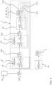
FIG. 3 shows an example of theclutch arrangement 6. Theclutch arrangement 6 comprises theclutch plate 8. In the example oneclutch plate 8 is arranged. In other examples two or more clutch plates may be arranged in theclutch arrangement 6. Theclutch plate 8 is activated by theclutch piston 9. According to the example, theclutch piston 9 is configured to be actuated by the firsthydraulic area 10 and/or the secondhydraulic area 11. In the example ofFIG. 3 , the firsthydraulic area 10 is smaller than the secondhydraulic area 11. In another example, the first hydraulic area may be larger than the second hydraulic area. The firsthydraulic area 10 is pressurized by the electrically controlledproportional pressure valve 12 and the secondhydraulic area 11 is pressurized by the electrically controlled on/offvalve 13, and thecontrol unit 7 is operatively connected with the electrically controlledproportional pressure valve 12 and the electrically controlled on/offvalve 13. In the example, apump 15 is delivering a hydraulic fluid to the firsthydraulic area 10 via the electrically controlledproportional pressure valve 12, and the secondhydraulic area 11 via the electrically controlled on/offvalve 13, respectively. Ahydraulic tank 16 is arranged in fluid communication with thepump 15. In addition, theinput unit 14 is operatively connected with thecontrol unit 7. - Furthermore, a
pressure sensor 17 is configured to measure an actuation pressure of theclutch arrangement 6. In the example, thepressure sensor 17 is arranged in connection with theclutch piston 9. In other examples, thepressure sensor 17 may be arranged in connection with other components of theclutch arrangement 6 for measuring and/or detecting the actuation pressure of the clutch arrangement. Also, a plurality of pressure sensors may be arranged for measuring and/or detecting the actuation pressure at different positions and at different components of theclutch arrangement 6. - Moreover, a
shunt resistor 18 may be arranged in connection with the electrically controlledproportional pressure valve 12 and/or the electrically controlled on/offvalve 13, theshunt resistor 18 is configured to measure a control current with a mA accuracy. In the example shown inFIG. 3 both the electrically controlledproportional pressure valve 12 and the electrically controlled on/offvalve 13 have ashunt resistor 18. - In
FIG. 4 , an overview of acontrol unit 7 according to an example is shown. In the example, thecontrol unit 7 comprises different sub-controllers which may control different components of the propulsion system 1 independently or in common. - The
control unit 7 may comprise apropeller speed controller 21, thepropeller speed controller 21 is configured to control the propeller speed on basis of the propeller speed references 200. Theinput unit 14 is configured to receive an input signal indicative of a propeller speed and to issue apropeller speed reference 200 based on the input signal. The actual propeller speed is detected atpoint 210 and is compared with the propeller speed references 200 in thepropeller speed controller 21. If a difference between thepropeller speed reference 200 and the detected propeller speed at 210 is observed thepropeller speed controller 21 will control the propeller speed accordingly so that the actual propeller speed at 210 will correspond to thepropeller speed reference 200. This may be provided with a closed-loop control. Thepropeller speed controller 21 comprises a feed-forward speed part 30. Based on speed reference magnitude, the feed-forward speed part 30 roughly calculate the pressure needed to reach intended rpm, under nominal load conditions. The feed-back speed part of the propeller speed controller is intended to compensate for differences from nominal load conditions, due to current, fouling or dents on propeller(s), varying friction in transmission, etc. - The
control unit 7 may also comprise anactuation pressure controller 20, theactuation pressure controller 20 is configured to control the actuation pressure on basis of thepressure reference 201 and/or the measured actuation pressure. The one ormore pressure sensors 17 are operatively connected with theactuation pressure controller 20. The pressure sensor(s) 17 is/are configured to measure forward and/or reverse actuation pressure atpoint 211, the measuredactuation pressure 211 is used as feedback to theactuation pressure controller 20. Theactuation pressure controller 20 is configured to control the actuation pressure of theclutch arrangement 6 by a closed-loop control. The actual actuation pressure is detected atpoint 211 and is compared with thepressure reference 201 in theactuation propeller controller 20. If a difference between thepressure reference 201 and the measuredactuation pressure 211 is observed, theactuation pressure controller 20 will control the actuation pressure accordingly so that the actual actuation pressure at 211 will correspond to thepressure reference 201. Theactuation pressure controller 20 comprises a feed-forward pressure part 31. Based on pressure reference magnitude, the feed-forward pressure part 31 may calculate the current that shall be applied to the electrically controlledproportional pressure valve 12 and/or the electrically controlled on/offvalve 13, to obtain the intended pressure. These calculations may be based on stated current to pressure characteristics of the electrically controlledproportional pressure valve 12 and the electrically controlled on/offvalve 13. The feed-back part of the actuation pressure controller is intended to compensate for differences from nominal valve characteristics due to variations in oil temperature, valve hysteresis, etc. - The
control unit 7 may also comprise acurrent controller 19, thecurrent controller 19 is configured to closed-loop current control the electrically controlledproportional pressure valve 12 and/or the electrically controlled on/offvalve 13 on basis of thecurrent reference 202. The shunt resistors 18 may be arranged in connection with the electrically controlledproportional pressure valve 12 and/or the electrically controlled on/offvalve 13, theshunt resistor 18 is configured to measure a control current atpoint 212 with a mA accuracy. Thecurrent controller 19 is configured to closed-loop current control the electrically controlledproportional pressure valve 12 and/or the electrically controlled on/offvalve 13 on basis of the measured control current 212 and/or thecurrent reference 202. The actual control current is detected atpoint 212 and is compared with thecurrent reference 202 in thecurrent controller 19. If a difference between thecurrent reference 202 and the measured control current 212 is observed thecurrent controller 19 will control the current accordingly so that the actual current at 212 will correspond to thecurrent reference 202. As mentioned previously, thecurrent controller 19 compensates for temperature variations in valve coils, and implements dithering to minimize hysteresis caused by stiction of a valve body. - The
current controller 19 may have a control frequency of more than 500Hz, preferably more than 1kHz, more preferably more than 2kHz. - Moreover, the
current controller 19 may be configured to implement dithering of current 200Hz/±10mA to minimize hysteresis of the electrically controlled proportional pressure valve and/or the electrically controlled on/off valve. - The propulsion system 1 may further comprise an
engine controller 40, theengine controller 40 is configured to control an engine speed on basis ofpropeller speed reference 200. Theengine controller 40 is configured to increase engine speed near full clutch engagement so that the clutch engagement is kept below where slip-stick behavior of the clutch disc may occur. Furthermore, theengine controller 40 may be configured to reset engine speed to idle speed when the clutch is set for full engagement. The engine controller is a feed forward controller. - In addition, the
engine controller 40 may be operatively connected with theinput unit 14. Also, thecontrol unit 7 and theengine controller 40 may be operatively connected. - The
current controller 19, theactuation pressure controller 20, thepropeller speed controller 21 and/or theengine controller 40 may be operatively connected. - By combining the
current controller 19, theactuation pressure controller 20 and thepropeller speed controller 21 in thecontrol unit 7, an increase of the robustness of slip control is provided. The controllers together provides a very robust propeller low-speed control, with built in ability to protect the engine from overload and unintended stalling. - For example, during gearshifts the propeller speed controller may not be utilized. In this particular case the desired pressure (controller input) is ramped from low to high level, to achieve smooth acceleration of the propeller into full engagement, when the electrically controlled on/off valve is engaged.
- Furthermore, in a continuous "low propeller speed control" mode, both the
propeller speed controller 21, theactuation pressure controller 20 and thecurrent controller 19 are used for controlling the different components of the system 1. Moreover, in a gear engagement mode, theactuation pressure controller 20 and thecurrent controller 19 are used for controlling the different components of the system 1, but thepropeller speed controller 21 andengine speed controller 40 may be disregarded the control situation. - In
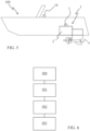
FIG. 5 , amarine vessel 100 is shown. Themarine vessel 100 comprises the propulsion system 1 as described above. In the example shown inFIG. 5 , thepropeller unit 3 is configured to pull themarine vessel 100. In another example the propeller unit may be configured to push the marine vessel. Theengine 2 is an internal combustion engine arranged onboard themarine vessel 100. -
FIG. 6 shows a schematic flow chart of the method of controlling a marine propulsion system 1 as described above. - In
step 500, a control unit is being provided and is operatively connected with the propeller unit, the transmission and the clutch arrangement. Instep 501, an input signal is received from the input unit. Instep 502, a propeller speed reference is issued based on the input signal instep 501. Instep 503, the propulsion system is controlled on basis on the propeller speed references 200 during varying operations and/or speed of the marine propulsion system 1. -
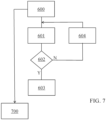
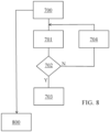
FIGS. 7-9 show schematic flow charts of the methods of controlling the different components of the propulsion system via the sub-controllers of thecontrol unit 7. - In
FIG. 7 , the schematic flow chart of the propeller speed controller is shown. Instep 600 the propeller speed reference is provided. Instep 601, the actual propeller speed is detected or measured. Instep 602, the actual propeller speed is compared with the propeller speed reference. If the actual propeller speed is substantial equal to the propeller speed reference it is continued to step 603. If the actual propeller speed is different from the propeller speed reference it is continued to step 604 wherein the propeller speed is either increased or decreased in view of the propeller speed reference. Based on speed reference magnitude, the feed-forward speed part roughly calculate pressure needed to reach intended rpm, under nominal load conditions. The feed-forward speed part instep 600 feeds the calculated pressure to step 700. The feed-back part is intended to compensate for differences from nominal load conditions, due to current, fouling or dents on propeller(s), varying friction of transmission, etc. - In
FIG. 8 , the schematic flow chart of the actuation pressure controller is shown. Instep 700, the actuation pressure reference is provided, for instance as described above. Instep 701, the actual actuation pressure is detected or measured. Instep 702, the actual actuation pressure is compared with the actuation pressure reference. If the actual actuation pressure is substantial equal to the actuation pressure reference it is continued to step 703. If the actual actuation pressure is different from the actuation pressure reference it is continued to step 704 wherein the actuation pressure is either increased or decreased in view of the actuation pressure reference. Based on pressure reference magnitude, the feed-forward pressure part calculate the current that shall be applied to the pressure valves to get the intended pressure. Calculation is based on stated current to pressure characteristics of valve. The feed-forward pressure part instep 700 feeds the calculated pressure to step 800. The feed-back part is intended to compensate for differences from nominal valve characteristics due to variations in oil temperature, valve hysteresis, etc. - In
FIG. 9 , the schematic flow chart of the current controller is shown. Instep 800, the current reference is provided. Instep 801, the actual current is detected or measured. Instep 802 the actual current is compared with the current reference. If the actual current is substantial equal to the current reference it is continued to step 803. If the actual current is different from the current reference it is continued to step 804 wherein the current is either increased or decreased in view of the current reference. As mentioned previously, the current controller compensates for temperature variations in valve coils, and implements dithering to minimize hysteresis caused by stiction of a valve body. - According to an example, a method for controlling a marine propulsion system 1 of the disclosure may comprising
- arranging a
clutch arrangement 6 comprising aclutch plate 8 and aclutch piston 9, theclutch piston 9 is configured to be actuated by a firsthydraulic area 10 and/or a secondhydraulic area 11, - pressurizing the first
hydraulic area 10 by an electrically controlledproportional pressure valve 12, - pressurizing the second
hydraulic area 11 by an electrically controlled on/offvalve 13, - controlling the electrically controlled
proportional pressure valve 12 independently of the electrically controlled on/offvalve 13 or vice versa. - Certain aspects and variants of the disclosure are set forth in the following examples numbered consecutive below.
- Example 1: A marine propulsion system (1) for a marine vessel (100), comprising
- an engine (2),
- a propeller unit (3) comprising one or more propellers,
- a transmission (5) arranged between the motor and the propeller unit,
- a hydraulic clutch arrangement (6), the clutch arrangement is configured to control a power transfer between the engine and the propeller unit,
- a control unit (7),
- wherein the clutch arrangement (6) comprises a clutch plate (8) and a clutch piston (9), the clutch piston is configured to be actuated by a first hydraulic area (10) and/or a second hydraulic area (11), and
- wherein the first hydraulic area is pressurized by an electrically controlled proportional pressure valve (12) and the second hydraulic area is pressurized by an electrically controlled on/off valve (13), the control unit is operatively connected with the electrically controlled proportional pressure valve and the electrically controlled on/off valve, and is configured to control the electrically controlled proportional pressure valve and the electrically controlled on/off valve.
- Example 2: The marine propulsion system (1) of example 1, wherein the control unit (7) is configured to control the electrically controlled proportional pressure valve (12) independently of the electrically controlled on/off valve (13), or the control unit (7) is configured to control the electrically controlled on/off valve (13) independently of the electrically controlled proportional pressure valve (12).
- Example 3: The marine propulsion system (1) of any of the preceding examples, further comprising an input unit (14) for adjusting a speed of the marine vessel in a forward direction and/or in a reverse direction.
- Example 4: The marine propulsion system (1) of example 3, wherein the control unit (7) is operatively connected with the input unit (14).
- Example 5: The marine propulsion system (1) of any of the preceding examples, wherein the first hydraulic area (10) is substantially equal in size to the second hydraulic area (11), the first hydraulic area being smaller than the second hydraulic area, or the first hydraulic area being larger than the second hydraulic area.
- Example 6: The marine propulsion system (1) of any of the preceding examples, wherein the clutch arrangement (6) has a predetermined actuation pressure, the predetermined actuation pressure is a pressure reference.
- Example 7: The marine propulsion system (1) of any of the preceding examples, wherein the control unit (7) comprises a current controller (19), the current controller is configured to closed-loop current control the electrically controlled proportional pressure valve and/or the electrically controlled on/off valve.
- Example 8: The marine propulsion system (1) of any of the preceding examples, wherein the electrically controlled proportional pressure valve (12) and/or the electrically controlled on/off valve (13) is/are controlled by a predetermined current, the predetermined current is a current reference.
- Example 9: The marine propulsion system (1) of example 7, wherein the current controller has a control frequency of more than 500Hz, preferably more than 1kHz, more preferably more than 2kHz.
- Example 10: The marine propulsion system (1) of any of the examples 7 to 9, wherein the current controller (19) is configured to implement dithering of current 200Hz/±10mA to minimize hysteresis of the electrically controlled proportional pressure valve and/or the electrically controlled on/off valve.
- Example 11: The marine propulsion system (1) of any of examples 7 to 10, wherein a shunt resistor (18) is arranged in connection with the electrically controlled proportional pressure valve and/or the electrically controlled on/off valve, the shunt resistor is configured to measure a control current with a mA accuracy.
- Example 12: The marine propulsion system (1) of any of the preceding examples, further comprising one or more pressure sensor(s) (17) being configured to measure an actuation pressure of the clutch arrangement.
- Example 13: The marine propulsion system (1) of any of the preceding examples, wherein the control unit (7) comprises an actuation pressure controller (20), the actuation pressure controller is configured to control the actuation pressure on basis of the pressure reference.
- Example 14: The marine propulsion system (1) of example 13, wherein the one or more pressure sensors (17) are operatively connected with the actuation pressure controller (20).
- Example 15: The marine propulsion system (1) of any of the examples 12 to 14, wherein the pressure sensor(s) (17) is/are configured to measure forward and/or reverse actuation pressure, the measured actuation pressure is used as feedback to the actuation pressure controller (20).
- Example 16: The marine propulsion system of any of the examples 13 to 15, wherein the actuation pressure controller (20) is configured to control the actuation pressure of the clutch arrangement (6) by a closed-loop control.
- Example 17: The marine propulsion system (1) of any of the preceding examples, wherein the control unit (7) further comprises a propeller speed controller (21), the propeller speed controller is configured to control the propeller speed on basis of the propeller speed references (200).
- Example 18: The marine propulsion system (1) of any of the preceding examples, further comprises an engine controller (40) configured to control an engine speed so as to avoid region with slip-stick near full clutch engagement.
- Example 19: The marine propulsion system (1) of any of the preceding examples, wherein the clutch arrangement (6) comprises a forward clutch unit and a reverse clutch unit.
- Example 20: The marine propulsion system (1) of any of the preceding examples, wherein the clutch arrangement comprises a plurality of clutch plates.
- Example 21: The marine propulsion system (1) of any of the preceding examples, further comprises an additional engine or engines.
- Example 22: The marine propulsion system (1) of any of the preceding examples, wherein the propeller unit (3) is configured to pull the marine vessel and/or is configured to push the marine vessel.
- Example 23: A marine vessel (100) comprising a marine propulsion system (1) of any of the preceding examples.
- Example 24:A method for controlling a marine propulsion system (1) of any of the examples 1 to 22, comprising
- arranging a clutch arrangement (6) comprising a clutch plate and a clutch piston, the clutch piston is configured to be actuated by a first hydraulic area (10) and/or a second hydraulic area (11),
- pressurizing the first hydraulic area by an electrically controlled proportional pressure valve (12),
- pressurizing the second hydraulic area by an electrically controlled on/off valve (13), controlling the electrically controlled proportional pressure valve (12) independently of the electrically controlled on/off valve (13) or vice versa.
- Example 25: The method of example 24, further comprising
- providing a propeller speed controller (21),
- controlling the propeller speed on basis of the propeller speed references (200).
- Example 26: The method of example 24 and/or 25, further comprising setting and/or calculating a predetermined actuation pressure, the predetermined actuation pressure is a pressure reference.
- Example 27: The method of any of the examples 24 to 26, further comprising measuring an actuation pressure of the clutch arrangement.
- Example 28: The method of example 27, further comprising
- providing an actuation pressure controller (20),
- controlling the actuation pressure on basis of the reference pressure and/or the measured actuation pressure.
- Example 29: The method of example 28, further comprising
- measuring forward and/or reverse actuation pressure,
- applying the measured actuation pressure as feedback to the actuation pressure controller (20).
- Example 30: The method of any of the examples 28 and/or 29, further comprising controlling the actuation pressure of the clutch arrangement by a closed-loop control.
- Example 31: The method of any of the examples 24 to 30, further comprising pressurizing a hydraulic area by at least an electrically controlled valve, an electrically controlled proportional pressure valve and/or an electrically controlled on/off valve.
- Example 32: The method of example 31, further comprising
- determining and/or calculating a predetermined current, the predetermined current is a current reference,
- providing a current controller (19),
- controlling by a closed-loop current control the electrically controlled valve, the electrically controlled proportional pressure valve and/or the electrically controlled on/off valve on basis of the current reference.
- Example 33: The method of example 32, further comprising controlling with a control frequency of more than 500Hz, preferably more than 1kHz, more preferably more than 2kHz.
- Example 34: The method of example 31 and/or 32, further comprising implementing dithering of current 200Hz/±10mA to minimize hysteresis of the electrically controlled valve, the electrically controlled proportional pressure valve and/or the electrically controlled on/off valve.
- Example 35: The method of any of the examples 31 to 34, further comprising providing a shunt resistor (18) in connection with the electrically controlled valve, the electrically controlled proportional pressure valve and/or the electrically controlled on/off valve,
measuring a control current with a mA accuracy by the shunt resistor. - Example 36: The method of example 35, further comprising controlling by a closed-loop current control the electrically controlled proportional pressure valve and/or the electrically controlled on/off valve on basis of the measured control current and/or the current reference.
- Example 37: The method of any of the examples 24 to 36, further comprising providing an engine controller (40),
controlling an engine speed on basis of an input of the operator. - Example 38: The method of example 37, further comprising increasing engine speed near full clutch engagement so that the clutch engagement is kept below where slip-stick behavior of the clutch disc may occur.
- Example 39: The method of example 37 and/or 38, further comprising resetting engine speed to idle speed when the clutch is set for full engagement.
- The terminology used herein is for the purpose of describing particular aspects only and is not intended to be limiting of the disclosure. As used herein, the singular forms "a," "an," and "the" are intended to include the plural forms as well, unless the context clearly indicates otherwise. As used herein, the term "and/or" includes any and all combinations of one or more of the associated listed items. It will be further understood that the terms "comprises," "comprising," "includes," and/or "including" when used herein specify the presence of stated features, integers, actions, steps, operations, elements, and/or components, but do not preclude the presence or addition of one or more other features, integers, actions, steps, operations, elements, components, and/or groups thereof.
- It will be understood that, although the terms first, second, etc., may be used herein to describe various elements, these elements should not be limited by these terms. These terms are only used to distinguish one element from another. For example, a first element could be termed a second element, and, similarly, a second element could be termed a first element without departing from the scope of the present disclosure.
- Relative terms such as "below" or "above" or "upper" or "lower" or "horizontal" or "vertical" may be used herein to describe a relationship of one element to another element as illustrated in the Figures. It will be understood that these terms and those discussed above are intended to encompass different orientations of the device in addition to the orientation depicted in the Figures. It will be understood that when an element is referred to as being "connected" or "coupled" to another element, it can be directly connected or coupled to the other element, or intervening elements may be present. In contrast, when an element is referred to as being "directly connected" or "directly coupled" to another element, there are no intervening elements present.
- Unless otherwise defined, all terms (including technical and scientific terms) used herein have the same meaning as commonly understood by one of ordinary skill in the art to which this disclosure belongs. It will be further understood that terms used herein should be interpreted as having a meaning consistent with their meaning in the context of this specification and the relevant art and will not be interpreted in an idealized or overly formal sense unless expressly so defined herein.
- It is to be understood that the present disclosure is not limited to the aspects described above and illustrated in the drawings; rather, the skilled person will recognize that many changes and modifications may be made within the scope of the present disclosure and appended claims. In the drawings and specification, there have been disclosed aspects for purposes of illustration only and not for purposes of limitation, the scope of the disclosure being set forth in the following claims.
Claims (15)
- A marine propulsion system (1) for a marine vessel (100), comprising- an engine (2),- a propeller unit (3) comprising one or more propellers (4a, 4b),- a transmission (5) arranged between the engine (2) and the propeller unit (3),- a hydraulic clutch arrangement (6), the clutch arrangement is configured to control a power transfer between the engine and the propeller unit,- a control unit (7),wherein the clutch arrangement (6) comprises a clutch plate (8) and a clutch piston (9), the clutch piston (9) is configured to be actuated by a first hydraulic area (10) and/or a second hydraulic area (11), andwherein the first hydraulic area (10) is pressurized by an electrically controlled proportional pressure valve (12) and the second hydraulic area (11) is pressurized by an electrically controlled on/off valve (13), the control unit (7) is operatively connected with the electrically controlled proportional pressure valve (12) and the electrically controlled on/off valve (13), and is configured to control the electrically controlled proportional pressure valve (12) and the electrically controlled on/off valve (13).
- The marine propulsion system (1) of claim 1, wherein the control unit (7) is configured to control the electrically controlled proportional pressure valve (12) independently of the electrically controlled on/off valve (13), or the control unit (7) is configured to control the electrically controlled on/off valve (13) independently of the electrically controlled proportional pressure valve (12).
- The marine propulsion system (1) of any of the preceding claims, further comprising an input unit (14) for adjusting a speed of the marine vessel in a forward direction and/or in a reverse direction.
- The marine propulsion system (1) of claim 3, wherein the control unit (7) is operatively connected with the input unit (14).
- The marine propulsion system (1) of any of the preceding claims, wherein the first hydraulic area (10) is substantially equal in size to the second hydraulic area (11), the first hydraulic area (10) being smaller than the second hydraulic area (11), or the first hydraulic area (10) being larger than the second hydraulic area (12).
- The marine propulsion system (1) of any of the preceding claims, wherein the control unit (7) comprises a current controller (19), the current controller is configured to closed-loop current control the electrically controlled proportional pressure valve (12) and/or the electrically controlled on/off valve (13).
- The marine propulsion system (1) of any of the preceding claims, further comprising one or more pressure sensor(s) (17) being configured to measure an actuation pressure of the clutch arrangement (6).
- The marine propulsion system (1) of any of the preceding claims, wherein the control unit (7) comprises an actuation pressure controller (20).
- The marine propulsion system (1) of claim 7, wherein the one or more pressure sensors (17) are operatively connected with the actuation pressure controller (20).
- The marine propulsion system (1) of any of the claims 7 to 9, wherein the pressure sensor(s) (17) is/are configured to measure forward and/or reverse actuation pressure, the measured actuation pressure is used as feedback to the actuation pressure controller (20).
- The marine propulsion system (1) of any of the claims 7 to 10, wherein the actuation pressure controller (20) is configured to control the actuation pressure of the clutch arrangement (6) by a closed-loop control.
- The marine propulsion system (1) of any of the preceding claims, further comprising a propeller speed controller (21).
- The marine propulsion system (1) of any of the preceding claims, further comprising an engine controller (40) configured to control an engine speed so as to avoid region with slip-stick near full clutch engagement.
- A marine vessel (100) comprising a marine propulsion system (1) of any of the preceding claims.
- A method for controlling a marine propulsion system (1) of any of the claims 1 to 13, comprisingarranging a clutch arrangement (6) comprising a clutch plate (8) and a clutch piston (9), the clutch piston (9) is configured to be actuated by a first hydraulic area (10) and/or a second hydraulic area (11),pressurizing the first hydraulic area (10) by an electrically controlled proportional pressure valve (12),pressurizing the second hydraulic area (11) by an electrically controlled on/off valve (13), controlling the electrically controlled proportional pressure valve (12) independently of the electrically controlled on/off valve (13) or vice versa.
Priority Applications (3)
| Application Number | Priority Date | Filing Date | Title |
|---|---|---|---|
| EP23205494.0A EP4545398B1 (en) | 2023-10-24 | 2023-10-24 | A marine propulsion system |
| US18/910,817 US20250128805A1 (en) | 2023-10-24 | 2024-10-09 | A marine propulsion system |
| CN202411452073.4A CN119872852A (en) | 2023-10-24 | 2024-10-17 | Ship propulsion system |
Applications Claiming Priority (1)
| Application Number | Priority Date | Filing Date | Title |
|---|---|---|---|
| EP23205494.0A EP4545398B1 (en) | 2023-10-24 | 2023-10-24 | A marine propulsion system |
Publications (2)
| Publication Number | Publication Date |
|---|---|
| EP4545398A1 true EP4545398A1 (en) | 2025-04-30 |
| EP4545398B1 EP4545398B1 (en) | 2025-11-26 |
Family
ID=88511216
Family Applications (1)
| Application Number | Title | Priority Date | Filing Date |
|---|---|---|---|
| EP23205494.0A Active EP4545398B1 (en) | 2023-10-24 | 2023-10-24 | A marine propulsion system |
Country Status (3)
| Country | Link |
|---|---|
| US (1) | US20250128805A1 (en) |
| EP (1) | EP4545398B1 (en) |
| CN (1) | CN119872852A (en) |
Citations (2)
| Publication number | Priority date | Publication date | Assignee | Title |
|---|---|---|---|---|
| US5766047A (en) * | 1996-09-25 | 1998-06-16 | Brunswick Corporation | Twin propeller marine propulsion unit |
| US20100121505A1 (en) * | 2005-07-20 | 2010-05-13 | Toyota Jidosha Kabushiki Kaisha | Ship maneuvering device |
-
2023
- 2023-10-24 EP EP23205494.0A patent/EP4545398B1/en active Active
-
2024
- 2024-10-09 US US18/910,817 patent/US20250128805A1/en active Pending
- 2024-10-17 CN CN202411452073.4A patent/CN119872852A/en active Pending
Patent Citations (2)
| Publication number | Priority date | Publication date | Assignee | Title |
|---|---|---|---|---|
| US5766047A (en) * | 1996-09-25 | 1998-06-16 | Brunswick Corporation | Twin propeller marine propulsion unit |
| US20100121505A1 (en) * | 2005-07-20 | 2010-05-13 | Toyota Jidosha Kabushiki Kaisha | Ship maneuvering device |
Also Published As
| Publication number | Publication date |
|---|---|
| US20250128805A1 (en) | 2025-04-24 |
| CN119872852A (en) | 2025-04-25 |
| EP4545398B1 (en) | 2025-11-26 |
Similar Documents
| Publication | Publication Date | Title |
|---|---|---|
| US8113892B1 (en) | Steering control system for a watercraft with three or more actuators | |
| EP2113672B1 (en) | Arrangement for operating a hydraulic device | |
| CN110177741B (en) | Method for operating a vessel comprising a plurality of propulsion units | |
| US9441724B1 (en) | Method and system for monitoring and controlling a transmission | |
| JP6214075B1 (en) | Ship propulsion method and ship propulsion device | |
| US20080045093A1 (en) | De-Coupling Clutch, Particularly for Marine Use | |
| EP1908684A1 (en) | Ship maneuvering device | |
| US10794474B1 (en) | System and method for controlling a transmission on a marine engine | |
| US9529965B2 (en) | Clutch slip recovery system and method | |
| US8690621B2 (en) | Outboard motor control apparatus | |
| WO2001017849A1 (en) | Method of hydraulically controlling a marine speed reducing and reversing machine in crash astern operation | |
| JP2024139552A (en) | Vessel control system and method for controlling a vessel - Patents.com | |
| US8011984B2 (en) | Boat propulsion system | |
| CN114728688A (en) | Propulsion and braking system using clutch | |
| EP4545398B1 (en) | A marine propulsion system | |
| JP2019131178A (en) | System and method for controlling propulsion of vessel | |
| US8038489B2 (en) | Boat propulsion system, and control device and control method for the same | |
| EP4545397A1 (en) | Marine propulsion system | |
| JP3476931B2 (en) | Ship propulsion agency | |
| EP4373740B1 (en) | Marine propulsion control system with syncronized troll and method of operation | |
| EP2990327B1 (en) | Marine vessel power system and method | |
| JP3712780B2 (en) | Ship propulsion organization | |
| US6853891B2 (en) | Low speed shift strategy for marine engines | |
| EP1680320A1 (en) | Decoupling clutch, particularly for marine | |
| JP3968145B2 (en) | Marine hydraulic clutch control method and apparatus |
Legal Events
| Date | Code | Title | Description |
|---|---|---|---|
| PUAI | Public reference made under article 153(3) epc to a published international application that has entered the european phase |
Free format text: ORIGINAL CODE: 0009012 |
|
| STAA | Information on the status of an ep patent application or granted ep patent |
Free format text: STATUS: REQUEST FOR EXAMINATION WAS MADE |
|
| 17P | Request for examination filed |
Effective date: 20241008 |
|
| AK | Designated contracting states |
Kind code of ref document: A1 Designated state(s): AL AT BE BG CH CY CZ DE DK EE ES FI FR GB GR HR HU IE IS IT LI LT LU LV MC ME MK MT NL NO PL PT RO RS SE SI SK SM TR |
|
| GRAP | Despatch of communication of intention to grant a patent |
Free format text: ORIGINAL CODE: EPIDOSNIGR1 |
|
| STAA | Information on the status of an ep patent application or granted ep patent |
Free format text: STATUS: GRANT OF PATENT IS INTENDED |
|
| INTG | Intention to grant announced |
Effective date: 20250901 |
|
| RIN1 | Information on inventor provided before grant (corrected) |
Inventor name: KANG, ANDREAS |
|
| GRAS | Grant fee paid |
Free format text: ORIGINAL CODE: EPIDOSNIGR3 |
|
| GRAA | (expected) grant |
Free format text: ORIGINAL CODE: 0009210 |
|
| STAA | Information on the status of an ep patent application or granted ep patent |
Free format text: STATUS: THE PATENT HAS BEEN GRANTED |
|
| AK | Designated contracting states |
Kind code of ref document: B1 Designated state(s): AL AT BE BG CH CY CZ DE DK EE ES FI FR GB GR HR HU IE IS IT LI LT LU LV MC ME MK MT NL NO PL PT RO RS SE SI SK SM TR |
|
| REG | Reference to a national code |
Ref country code: CH Ref legal event code: F10 Free format text: ST27 STATUS EVENT CODE: U-0-0-F10-F00 (AS PROVIDED BY THE NATIONAL OFFICE) Effective date: 20251126 Ref country code: GB Ref legal event code: FG4D |
|
| REG | Reference to a national code |
Ref country code: IE Ref legal event code: FG4D |
|
| REG | Reference to a national code |
Ref country code: DE Ref legal event code: R096 Ref document number: 602023008978 Country of ref document: DE |
|
| REG | Reference to a national code |
Ref country code: NL Ref legal event code: MP Effective date: 20251126 |
|
| PG25 | Lapsed in a contracting state [announced via postgrant information from national office to epo] |
Ref country code: ES Free format text: LAPSE BECAUSE OF FAILURE TO SUBMIT A TRANSLATION OF THE DESCRIPTION OR TO PAY THE FEE WITHIN THE PRESCRIBED TIME-LIMIT Effective date: 20251126 |
|
| REG | Reference to a national code |
Ref country code: LT Ref legal event code: MG9D |
|
| PG25 | Lapsed in a contracting state [announced via postgrant information from national office to epo] |
Ref country code: NO Free format text: LAPSE BECAUSE OF FAILURE TO SUBMIT A TRANSLATION OF THE DESCRIPTION OR TO PAY THE FEE WITHIN THE PRESCRIBED TIME-LIMIT Effective date: 20260226 |
|
| PG25 | Lapsed in a contracting state [announced via postgrant information from national office to epo] |
Ref country code: FI Free format text: LAPSE BECAUSE OF FAILURE TO SUBMIT A TRANSLATION OF THE DESCRIPTION OR TO PAY THE FEE WITHIN THE PRESCRIBED TIME-LIMIT Effective date: 20251126 Ref country code: AT Free format text: LAPSE BECAUSE OF FAILURE TO SUBMIT A TRANSLATION OF THE DESCRIPTION OR TO PAY THE FEE WITHIN THE PRESCRIBED TIME-LIMIT Effective date: 20251126 Ref country code: HR Free format text: LAPSE BECAUSE OF FAILURE TO SUBMIT A TRANSLATION OF THE DESCRIPTION OR TO PAY THE FEE WITHIN THE PRESCRIBED TIME-LIMIT Effective date: 20251126 |
|
| REG | Reference to a national code |
Ref country code: AT Ref legal event code: MK05 Ref document number: 1860844 Country of ref document: AT Kind code of ref document: T Effective date: 20251126 |
|
| PG25 | Lapsed in a contracting state [announced via postgrant information from national office to epo] |
Ref country code: NL Free format text: LAPSE BECAUSE OF FAILURE TO SUBMIT A TRANSLATION OF THE DESCRIPTION OR TO PAY THE FEE WITHIN THE PRESCRIBED TIME-LIMIT Effective date: 20251126 |
|
| PG25 | Lapsed in a contracting state [announced via postgrant information from national office to epo] |
Ref country code: RS Free format text: LAPSE BECAUSE OF FAILURE TO SUBMIT A TRANSLATION OF THE DESCRIPTION OR TO PAY THE FEE WITHIN THE PRESCRIBED TIME-LIMIT Effective date: 20260226 |
|
| PG25 | Lapsed in a contracting state [announced via postgrant information from national office to epo] |
Ref country code: IS Free format text: LAPSE BECAUSE OF FAILURE TO SUBMIT A TRANSLATION OF THE DESCRIPTION OR TO PAY THE FEE WITHIN THE PRESCRIBED TIME-LIMIT Effective date: 20260326 |
|
| PG25 | Lapsed in a contracting state [announced via postgrant information from national office to epo] |
Ref country code: PT Free format text: LAPSE BECAUSE OF FAILURE TO SUBMIT A TRANSLATION OF THE DESCRIPTION OR TO PAY THE FEE WITHIN THE PRESCRIBED TIME-LIMIT Effective date: 20260326 |
|
| PG25 | Lapsed in a contracting state [announced via postgrant information from national office to epo] |
Ref country code: PL Free format text: LAPSE BECAUSE OF FAILURE TO SUBMIT A TRANSLATION OF THE DESCRIPTION OR TO PAY THE FEE WITHIN THE PRESCRIBED TIME-LIMIT Effective date: 20251126 |
|
| PG25 | Lapsed in a contracting state [announced via postgrant information from national office to epo] |
Ref country code: LV Free format text: LAPSE BECAUSE OF FAILURE TO SUBMIT A TRANSLATION OF THE DESCRIPTION OR TO PAY THE FEE WITHIN THE PRESCRIBED TIME-LIMIT Effective date: 20251126 |
|
| PG25 | Lapsed in a contracting state [announced via postgrant information from national office to epo] |
Ref country code: BG Free format text: LAPSE BECAUSE OF FAILURE TO SUBMIT A TRANSLATION OF THE DESCRIPTION OR TO PAY THE FEE WITHIN THE PRESCRIBED TIME-LIMIT Effective date: 20251126 |
|
| PG25 | Lapsed in a contracting state [announced via postgrant information from national office to epo] |
Ref country code: LT Free format text: LAPSE BECAUSE OF FAILURE TO SUBMIT A TRANSLATION OF THE DESCRIPTION OR TO PAY THE FEE WITHIN THE PRESCRIBED TIME-LIMIT Effective date: 20251126 |
|
| PG25 | Lapsed in a contracting state [announced via postgrant information from national office to epo] |
Ref country code: SM Free format text: LAPSE BECAUSE OF FAILURE TO SUBMIT A TRANSLATION OF THE DESCRIPTION OR TO PAY THE FEE WITHIN THE PRESCRIBED TIME-LIMIT Effective date: 20251126 |
|
| PG25 | Lapsed in a contracting state [announced via postgrant information from national office to epo] |
Ref country code: DK Free format text: LAPSE BECAUSE OF FAILURE TO SUBMIT A TRANSLATION OF THE DESCRIPTION OR TO PAY THE FEE WITHIN THE PRESCRIBED TIME-LIMIT Effective date: 20251126 |
|
| PG25 | Lapsed in a contracting state [announced via postgrant information from national office to epo] |
Ref country code: EE Free format text: LAPSE BECAUSE OF FAILURE TO SUBMIT A TRANSLATION OF THE DESCRIPTION OR TO PAY THE FEE WITHIN THE PRESCRIBED TIME-LIMIT Effective date: 20251126 |
|
| PG25 | Lapsed in a contracting state [announced via postgrant information from national office to epo] |
Ref country code: CZ Free format text: LAPSE BECAUSE OF FAILURE TO SUBMIT A TRANSLATION OF THE DESCRIPTION OR TO PAY THE FEE WITHIN THE PRESCRIBED TIME-LIMIT Effective date: 20251126 |
|
| PG25 | Lapsed in a contracting state [announced via postgrant information from national office to epo] |
Ref country code: SK Free format text: LAPSE BECAUSE OF FAILURE TO SUBMIT A TRANSLATION OF THE DESCRIPTION OR TO PAY THE FEE WITHIN THE PRESCRIBED TIME-LIMIT Effective date: 20251126 |
|
| PG25 | Lapsed in a contracting state [announced via postgrant information from national office to epo] |
Ref country code: SE Free format text: LAPSE BECAUSE OF FAILURE TO SUBMIT A TRANSLATION OF THE DESCRIPTION OR TO PAY THE FEE WITHIN THE PRESCRIBED TIME-LIMIT Effective date: 20251126 |