EP4545385A1 - Vehicle chassis with an adapter for mounting a component - Google Patents
Vehicle chassis with an adapter for mounting a component Download PDFInfo
- Publication number
- EP4545385A1 EP4545385A1 EP24208768.2A EP24208768A EP4545385A1 EP 4545385 A1 EP4545385 A1 EP 4545385A1 EP 24208768 A EP24208768 A EP 24208768A EP 4545385 A1 EP4545385 A1 EP 4545385A1
- Authority
- EP
- European Patent Office
- Prior art keywords
- chassis
- component
- profile
- adapter
- arm
- Prior art date
- Legal status (The legal status is an assumption and is not a legal conclusion. Google has not performed a legal analysis and makes no representation as to the accuracy of the status listed.)
- Pending
Links
Images


Classifications
-
- B—PERFORMING OPERATIONS; TRANSPORTING
- B62—LAND VEHICLES FOR TRAVELLING OTHERWISE THAN ON RAILS
- B62D—MOTOR VEHICLES; TRAILERS
- B62D33/00—Superstructures for load-carrying vehicles
- B62D33/077—Superstructures for load-carrying vehicles characterised by the connection of the superstructure to the vehicle frame
Definitions
- the present disclosure relates to a vehicle chassis with an adapter for mounting a component onto the chassis and a method thereof.
- heavy load vehicles such as trucks or tractor semi-trailers or combinations thereof in which the tractor vehicle pulls and partly supports the payload that is packed onto the semi-trailer.
- a typical truck comprises a chassis, wheels, a driveline, an engine, fuel tanks, a cabin and several other components.
- the chassis forms a back-bone of the vehicle on which the individual components are mounted.
- the heavy components such as driveline or the engine are lowered from above into the chassis until rested on an opposing bracket system. The component is then screwed with bolts tight together with the chassis from the top.
- the top-down assembly approach has a number of advantages. For instance, when the screwing bolts run loose during operation of the vehicle or after a maintenance activity, the heavy components cannot fall out of the chassis on the ground. Vertically lowering the component onto the bracket system minimizes the corresponding clearance penalty related to associated horizontal motions. The top-down assembly approach avoids cumbersome lifting of the vehicle or screwing bolts from beneath the vehicle with reduced accessibility for assembly mechanic.
- a typical driveline component is construed such that the whole packaging space available below the chassis beams is utilized for the purpose of installing and packing together all needed interfaces and module subcomponents into one large rigid encapsulating component.
- Integrating and assembling the component from beneath into the chassis is cumbersome or even hindered due to presence of the bracket system and/or limited accessibility to the mounting bolts used to attach the component to the bracket system. Often, additional space for aligning a component to the bracket system or vice versa needs to be taken into the account, thus limiting the size and/or the number of components that can be mounted onto the chassis.
- aspects of the present disclosure relate to a chassis of a vehicle provided with at least one chassis adapter for mounting a component onto the chassis.
- the chassis adapter comprises a first arm configured to at least partially support the component, a second arm comprising a contact face, and a fixation means configured to secure the chassis adapter onto the chassis.
- the second arm comprises a first profile and the chassis comprises a second profile shaped correspondingly to the first profile with an edge upstanding in a direction opposite to gravitational forces acting on the chassis.
- the chassis adapter is configured to mount the component onto the chassis by hooking the first profile of the second arm into the second profile of the chassis, thereby engaging the contact face of the second arm to the chassis, and by positioning the first arm at least partially under the component, thereby attaching the component to the first arm.
- the contact face is secured to the chassis by the fixation means to prevent displacement of the first profile from the second profile, e.g., during a bumpy ride of the vehicle.
- chassis adapter with a first profile comprising a protrusion e.g. in the form of a wedge-, ball-, cylinder-, hook- or any other geometric shape that provides for a form-locking mechanism, and the second profile with a corresponding shape for receiving said first profile, self-alignment of the chassis adapter to the chassis can be realized, thus simplifying the mounting of the component to the chassis.
- a protrusion e.g. in the form of a wedge-, ball-, cylinder-, hook- or any other geometric shape that provides for a form-locking mechanism
- the chassis adapter which is relatively light and small with respect to the component, can be hooked at a position which is the most optimal to attach and/or support the component, for example the closest or the easiest position to access, preferably at a stable chassis location on or adjacent to a cross member in a typical ladder frame of a truck.
- the load of the component can be spread over the chassis, thereby lowering the risk of breaking the chassis during operation of the vehicle, e.g., when driving over a rough or wobbly terrain.
- a three-point-mounting system comprising three elastomeric bushings arranged between the chassis adapter and the component can be utilized to absorb chassis torsional deformations and/or vibrations caused by the load of the component onto the chassis.
- the chassis adapter By providing the chassis adapter with an L-shape, the chassis adapter can be arranged under the component, therefore providing the maximum space for the component in the lateral direction, e.g., extending from one chassis beam to the other.
- chassis adapters with a reinforcement structure reinforcing the connection between the second arm and the first arm of the chassis adapter, load carrying capacity and/or stiffness of the chassis adapter can be increased by at least a factor of two and/or less chassis adapters can be used for mounting the same amount of load.
- both a component under the chassis and a bridge member above the chassis can be mounted to said bracket.
- various components can be mounted to the chassis adapter, e.g., components of different shapes and/or materials.
- an attachment means e.g., bolts or plugs
- the mount part and/or the chassis adapter with an elastomeric bushing, mechanical vibrations of the component can be reduced and/or isolated.
- the component by providing the component with an inverted T-shape, size of the component that can fit in the storage space underneath the chassis can be maximized.
- extra free space in the storage space underneath the chassis can be provided for, e.g., air ducts sideways connecting to the storage unit, or cabling, tubing or other kind of connections and/or attachments that need to be arranged adjacent to the component.
- the maximum drive range of the vehicle can be extended.
- the component by providing lifting support to the component, the component can be guided from below into the chassis thereby bypassing obstacles present on or above the chassis, e.g., a central cross member connecting two longitudinal chassis beams, thus allowing attaching a chassis adaptor to the chassis and underneath the component and/or its respective mount part.
- obstacles present on or above the chassis e.g., a central cross member connecting two longitudinal chassis beams, thus allowing attaching a chassis adaptor to the chassis and underneath the component and/or its respective mount part.
- the component by providing the component with a lifting support moving in a straight vertical line and mounting the component with the form-locking chassis adapter, there is no need for horizontal maneuvering of the component, thus simplifying the assembly process whilst minimizing the corresponding clearance penalty related to associated horizontal motions.
- the component By removing the lifting support to the component, the component is resided on the first arm of a chassis adapter and thereby the gravitational forces pulling on the chassis adapter are enhanced, thereby securing the form-locking mechanism of the chassis adapter to the chassis.
- chassis adapter By providing the chassis adapter with a compact design and lightweight material, the job of an assembly mechanic is eased because the chassis adapter can be easily and accurately inserted into the second profile on the chassis with only one hand whilst the other hand can be used for handling a mounting tool for providing the fixation means, e.g., using a screw driver to fasten a bolt.
- the advantageous technical effects of this disclosure contribute to a safe, healthy and ergonomically friendly working environment in a vehicle assembly factory while lowering the time needed to assemble the vehicle.
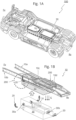
- FIGs 1A-B illustrate a chassis 10 of a vehicle 100 provided with at least one chassis adapter 20 for mounting 200 a driveline component 30, e.g., a fuel cell module, into the center of a chassis 10 in between two elongated chassis beams 10a, 10b.
- a driveline component e.g., a fuel cell module
- the chassis adapter 20 comprises a first arm 21 configured to at least partially support the component 30, and a second arm 22 comprising a contact face 23, fixation means 50a is configured to secure a form lock of the chassis adapter 20 onto the chassis 10.
- the first arm 21 transfers into the second arm 22 at an angle smaller than ⁇ radians, i.e. smaller than ninety degrees, preferably in a range from forty five up to one hundred and twenty degrees.
- the second arm 22 comprises a first profile 24.
- the chassis 10 comprises a second profile 11 shaped correspondingly to the first profile 24 with an edge upstanding in a direction opposite to gravitational forces G acting on the chassis 10.
- the chassis adapter 20 is configured to mount the component 30 onto the chassis 10 by providing the first arm 21 at least partially under the component 30, and hooking the first profile 24 of the second arm 22 into the second profile 11 of the chassis 10, thereby engaging the contact face 23 by a compressional force C, caused by the weight of the component 30 through a torsional moment M around an edge of the second profile 11.
- the second arm 22 of the chassis adapter 20 is hooked by the first profile 24 to the second profile 11 arranged on a first side of a chassis beam.
- the second arm 22 transfers into the first arm 21 towards a second side of the chassis beam for providing a torsional moment M around the edge.
- the contact face 23 is secured to the chassis 10 by a fixation means 50a, e.g., a bolt, a plug, a rivet, a snap-lock or other type of a fixation means to prevent vibrating loose, for instance during a bumpy ride.
- a fixation means 50a e.g., a bolt, a plug, a rivet, a snap-lock or other type of a fixation means to prevent vibrating loose, for instance during a bumpy ride.
- the fixation means 50a are realized by a combination of measures without applying a further securing device element like a bolt or a plug in the second arm 22.
- two attachment means 50b arranged at two opposing sides of the component 30 can be used to fixate two separate chassis adapters 20 in the lateral direction and a form-locking first profile 24, protruding into the chassis 10 material in both the vertical direction and also at least partly in the lateral direction as shown in FIG 3B , fixates the respective chassis adapter 20 in the vertical and horizontal directions, thereby securing the respective form locks of the two separate chassis adapters 20 on the chassis 10.
- the angle between the wedge-shaped first profile 24 and the second arm 22 is in a range between zero and ninety degrees, preferably in a range from twenty up to seventy degrees.
- the first profile 24 and its second profile 11 are shaped by a ball-shaped cross section geometry.
- the ball-shaped geometry protrudes (or hooks) into the chassis 10 material in both the vertical direction and also at least partly in the lateral direction for the purpose of reducing risk of vibrating loose during a bumpy ride.
- the first profile 24 of the second arm 22 embraced in a portion of the chassis 10.
- the chassis 10 comprises a plurality of second profiles configured to receive the first profile 24 of a chassis adapter 20 at a plurality of distinct positions.
- the chassis 10 comprises at least one chassis adapter 20 provided on each of at least two opposing sides of the chassis 10 and at least one another chassis adapter 20 provided on a cross member 10d laterally extending across the opposing sides of the chassis 10, e.g., at a location of the rear axle and below a fifth wheel coupling plate.
- the chassis adapter 20 is provided with an L-shape.
- the chassis adapter 20, which is connected to the cross member 10d at the rear Rv of the vehicle 100 comprises a reinforcement structure 20r provided on at least one side of the chassis adapter 20, thereby reinforcing the connection between the second arm 22 and the first arm 21 of the chassis adapter 20 to increase a load capacity of the chassis adapter 20 by at least a factor of two.
- the reinforcement structure 20r has a form of a plate.
- the chassis adapter 20 has a load capacity of at least ten, preferably at least hundred times more than the static gravitational load on the chassis adapter 20.
- At least one chassis adapter 20 is arranged at the front Fv of the vehicle on each of the elongated chassis beams 10a, 10b and at least one another chassis adapter 20 is arranged on the cross member 10d at the rear Rv of the vehicle 100.
- the chassis adapter 20 deforms by less than half of a millimeter when exposed to a load capacity of at least one thousand kilograms.
- the second profile 11 is comprised on a bracket 60 arranged on the chassis 10.
- the first profile 24 of the chassis adapter 20 is configured by shape with limited compact dimensions in height and width to be accurately positioned (also in longitudinal direction) and/or hooked into a corresponding second profile 11 hole forming part of the bracket 60. This eases the mounting operation during assembly and contributes to a simple and compact design of the chassis adapter 20 (separately shown in FIG 4A and 4B ).
- FIG 2A illustrates a cross sectional view of the bracket system as illustrated in FIG 4B wherein the same first profile 24 and corresponding second profile 11 cut-out hole is visible.
- the fixation means 50a can be realized without the need for an additional securing bolt in the second arm 22 of the chassis adapter 20.
- the fixation means 50a can be realized by a combination of measures, advantageously by interconnecting two opposing chassis adapters 20 via the component 30 using the respective attachment means 50b and activating the form-locking mechanism by gravitational forces pulling on the respective chassis adapter 20.
- the bracket 60 is provided with an additional connection to a so-called cabin bridge (not shown), being construed by a straight or curved cross beam and facilitating further mounting points for the components (springs and dampers) of the cabin suspension, which also interconnects the two elongated chassis beams at the back of the cabin and thus forms an additional chassis cross member.
- the bracket 60 provides multiple functionality of facilitating mounting of the component 30 (e.g. fuel cell box) via the plurality of the chassis adapters 20 onto the chassis, and a connection of a front wheel mudguard support, a front axle leaf spring, and/or a hydrogen tank on a side of the chassis 10.
- the component 30 is provided with a plurality of mount parts 30a, 30b arranged between the component 30 and the chassis adapter 20, e.g., on a sidewall of the component 30.
- the plurality of mount parts 30a, 30b comprises an attachment means 50b configured to attach the respective mount part 30a, 30b to the first arm 21 of the chassis adapter 20, thereby mounting the component 30 to the chassis 10, e.g., as illustrated in FIG 4C .
- at least one of the plurality of mount parts 30a, 30b comprises a bushing 40 for guiding the attachment means 50b to the first arm 21 of the chassis adapter 20.
- the bushing 40 comprises an elastomeric material that transmits the forces between the chassis adapter 20 and the mount parts 30a,30b for the purpose of component vibration isolation and provision of local cardanic angle motions that typically occur during deformation of the chassis 10, e.g., in the case of the three-point mounting of the component 30 illustrated in FIG 1B and 4C .
- the attachment means 50b and/or the bushing 40 is accessible from above via a space in-between the component 30 and the chassis 10.
- the chassis 10 comprises a pair of elongated chassis beams 10a, 10b extending along the length of the vehicle 100.
- the chassis 10 comprises a central cross member 10c laterally extending across the chassis beams 10a, 10b.
- a storage space configured to receive a component 30 is provided between the chassis beams 10a, 10b extending underneath the cross member 10c.
- the component 30 is mounted in the storage space by at least one chassis adapter 20.
- a plurality of chassis adapters mounted on the elongated chassis beams 10a, 10b has mechanical properties different from a chassis adapter mounted on the cross member 10d, e.g., different axial and/or lateral stiffness or torsional properties which are provided by the elastomeric material comprised in the bushing 40.
- the bushing 40 on the cross member 10d provided at a rear R of a vehicle 100 has a lower stiffness than the plurality of chassis adapter bushings on the elongated beams at the front Fv of the vehicle 100, thereby accommodating for torsional and/or vertical vibrations of the component 30 at the rear Rv of the vehicle 100.
- the component 30 is provided with an inverted T-shape or a L-shape cross section extending into said storage space.
- the component 30 is a fuel cell configured to provide electric energy to the vehicle 100.
Landscapes
- Engineering & Computer Science (AREA)
- Chemical & Material Sciences (AREA)
- Combustion & Propulsion (AREA)
- Transportation (AREA)
- Mechanical Engineering (AREA)
- Body Structure For Vehicles (AREA)
Abstract
A chassis (10) of a vehicle provided with at least one chassis adapter (20) for mounting (200) a component (30) onto the chassis (10), wherein the chassis adapter (20) comprises a first arm for at least partially supporting the component (30), and a second arm comprising a contact face; wherein the second arm comprises a first profile; wherein the chassis (10) comprises a second profile; wherein the chassis adapter (20) is configured to mount (200) the component (30) onto the chassis (10) by positioning the first arm at least partially under the component (30), and hooking the first profile of the second arm into the second profile of the chassis (10), thereby engaging the contact face of the second arm to the chassis (10) and attaching the component (30) to the first arm.
Description
- The present disclosure relates to a vehicle chassis with an adapter for mounting a component onto the chassis and a method thereof.
- Of particular interest are heavy load vehicles such as trucks or tractor semi-trailers or combinations thereof in which the tractor vehicle pulls and partly supports the payload that is packed onto the semi-trailer.
- A typical truck comprises a chassis, wheels, a driveline, an engine, fuel tanks, a cabin and several other components. The chassis forms a back-bone of the vehicle on which the individual components are mounted. Presently, during assembling the trucks in the manufacturing plant, the heavy components such as driveline or the engine are lowered from above into the chassis until rested on an opposing bracket system. The component is then screwed with bolts tight together with the chassis from the top.
- The top-down assembly approach has a number of advantages. For instance, when the screwing bolts run loose during operation of the vehicle or after a maintenance activity, the heavy components cannot fall out of the chassis on the ground. Vertically lowering the component onto the bracket system minimizes the corresponding clearance penalty related to associated horizontal motions. The top-down assembly approach avoids cumbersome lifting of the vehicle or screwing bolts from beneath the vehicle with reduced accessibility for assembly mechanic.
- Due to the increasing electrification of the trucks and the associated use of electric motors and batteries having lower volumetric energy density in comparison to conventional fossil fuels (like diesel), more and/or bigger components need to mounted on the chassis. These components include an electrical driveline, an electric energy storage battery system, a hydrogen storage system and (a plurality) of fuel cell devices. Large volume hydrogen tanks are typically placed sideward of the chassis in between the front and rear wheels or behind the cabin wall in front of the semi-trailer. Traditionally, only the space in between or below the chassis remains available to accommodate the additional components such as the electrical driveline, an electric energy storage battery system or a plurality of fuel cell devices. However, some of these components need to interface with other parts of the vehicle, e.g., to a supply duct for coupling an air, to a hydrogen supply duct or a water drain duct. The size and geometry of the components and/or their interfaces make it difficult or even impossible to use the top-down assembly approach, because of the collision with chassis beams which have a limited distance between each other that is typically smaller than the size of the component. For example, a typical driveline component is construed such that the whole packaging space available below the chassis beams is utilized for the purpose of installing and packing together all needed interfaces and module subcomponents into one large rigid encapsulating component. Integrating and assembling the component from beneath into the chassis is cumbersome or even hindered due to presence of the bracket system and/or limited accessibility to the mounting bolts used to attach the component to the bracket system. Often, additional space for aligning a component to the bracket system or vice versa needs to be taken into the account, thus limiting the size and/or the number of components that can be mounted onto the chassis.
- Given the limitations of the present assembly approaches, there remains a need for a new space-efficient solution for mounting components onto a chassis of a vehicle.
- Aspects of the present disclosure relate to a chassis of a vehicle provided with at least one chassis adapter for mounting a component onto the chassis. The chassis adapter comprises a first arm configured to at least partially support the component, a second arm comprising a contact face, and a fixation means configured to secure the chassis adapter onto the chassis. In one aspect of the present disclosure, the second arm comprises a first profile and the chassis comprises a second profile shaped correspondingly to the first profile with an edge upstanding in a direction opposite to gravitational forces acting on the chassis. The chassis adapter is configured to mount the component onto the chassis by hooking the first profile of the second arm into the second profile of the chassis, thereby engaging the contact face of the second arm to the chassis, and by positioning the first arm at least partially under the component, thereby attaching the component to the first arm. In another aspect of the present disclosure, the contact face is secured to the chassis by the fixation means to prevent displacement of the first profile from the second profile, e.g., during a bumpy ride of the vehicle.
- By providing the chassis adapter with a first profile comprising a protrusion e.g. in the form of a wedge-, ball-, cylinder-, hook- or any other geometric shape that provides for a form-locking mechanism, and the second profile with a corresponding shape for receiving said first profile, self-alignment of the chassis adapter to the chassis can be realized, thus simplifying the mounting of the component to the chassis.
- Advantageously, by providing the chassis with a plurality of second profiles and/or a continuous second profile along a length or a width of the chassis, the chassis adapter, which is relatively light and small with respect to the component, can be hooked at a position which is the most optimal to attach and/or support the component, for example the closest or the easiest position to access, preferably at a stable chassis location on or adjacent to a cross member in a typical ladder frame of a truck.
- By providing a plurality of chassis adapters across the chassis, the load of the component can be spread over the chassis, thereby lowering the risk of breaking the chassis during operation of the vehicle, e.g., when driving over a rough or wobbly terrain. Alternatively, a three-point-mounting system comprising three elastomeric bushings arranged between the chassis adapter and the component can be utilized to absorb chassis torsional deformations and/or vibrations caused by the load of the component onto the chassis.
- By providing the chassis adapter with an L-shape, the chassis adapter can be arranged under the component, therefore providing the maximum space for the component in the lateral direction, e.g., extending from one chassis beam to the other.
- Advantageously, by providing the chassis adapters with a reinforcement structure reinforcing the connection between the second arm and the first arm of the chassis adapter, load carrying capacity and/or stiffness of the chassis adapter can be increased by at least a factor of two and/or less chassis adapters can be used for mounting the same amount of load.
- By providing a bracket between the chassis and the chassis adapter, both a component under the chassis and a bridge member above the chassis can be mounted to said bracket.
- By providing the component with a plurality of mount parts arranged between the component and the chassis adapter, various components can be mounted to the chassis adapter, e.g., components of different shapes and/or materials. By providing the respective mount part with a bushing, an attachment means, e.g., bolts or plugs, can be guided from the mount part to the chassis adapter, thereby easing attachment of the mount part to the chassis adapter. By providing the mount part and/or the chassis adapter with an elastomeric bushing, mechanical vibrations of the component can be reduced and/or isolated.
- Advantageously, by providing the component with an inverted T-shape, size of the component that can fit in the storage space underneath the chassis can be maximized. By providing the component with a L-shape, extra free space in the storage space underneath the chassis can be provided for, e.g., air ducts sideways connecting to the storage unit, or cabling, tubing or other kind of connections and/or attachments that need to be arranged adjacent to the component.
- By providing an electric vehicle with a component configured to store and/or extract electric energy, e.g., fuel cell, the maximum drive range of the vehicle can be extended.
- In one aspect of the invention, by providing lifting support to the component, the component can be guided from below into the chassis thereby bypassing obstacles present on or above the chassis, e.g., a central cross member connecting two longitudinal chassis beams, thus allowing attaching a chassis adaptor to the chassis and underneath the component and/or its respective mount part.
- Advantageously, by providing the component with a lifting support moving in a straight vertical line and mounting the component with the form-locking chassis adapter, there is no need for horizontal maneuvering of the component, thus simplifying the assembly process whilst minimizing the corresponding clearance penalty related to associated horizontal motions.
- By removing the lifting support to the component, the component is resided on the first arm of a chassis adapter and thereby the gravitational forces pulling on the chassis adapter are enhanced, thereby securing the form-locking mechanism of the chassis adapter to the chassis.
- By providing the chassis adapter with a compact design and lightweight material, the job of an assembly mechanic is eased because the chassis adapter can be easily and accurately inserted into the second profile on the chassis with only one hand whilst the other hand can be used for handling a mounting tool for providing the fixation means, e.g., using a screw driver to fasten a bolt.
- The advantageous technical effects of this disclosure contribute to a safe, healthy and ergonomically friendly working environment in a vehicle assembly factory while lowering the time needed to assemble the vehicle.
- These and other features, aspects, and advantages of the apparatus, systems and methods of the present disclosure will become better understood from the following description, appended claims, and accompanying drawing wherein:
-
FIGs 1A-B illustrate a chassis of a vehicle with a mounted component; -
FIGs 2A-C illustrate various aspects of mounting a component to a chassis according to an embodiment of the invention; -
FIGs 3A-C illustrate various embodiments of a chassis adapter; -
FIG 4A illustrates a reinforced chassis adapter; -
FIG 4B illustrates a bracket with an additional functionality of connecting a hydrogen storage system frame to the chassis at a back side of a vehicle cabin; -
FIG 4C illustrates accessibility of the chassis adapter for tools used to fasten attachment means of the chassis adapter from above a chassis. - Terminology used for describing particular embodiments is not intended to be limiting of the invention. As used herein, the singular forms "a", "an" and "the" are intended to include the plural forms as well, unless the context clearly indicates otherwise. The term "and/or" includes any and all combinations of one or more of the associated listed items. It will be understood that the terms "comprises" and/or "comprising" specify the presence of stated features but do not preclude the presence or addition of one or more other features. It will be further understood that when a particular step of a method is referred to as subsequent to another step, it can directly follow said other step or one or more intermediate steps may be carried out before carrying out the particular step, unless specified otherwise. Likewise it will be understood that when a connection between structures or components is described, this connection may be established directly or through intermediate structures or components unless specified otherwise.
- The invention is described more fully hereinafter with reference to the accompanying drawings, in which embodiments of the invention are shown. In the drawings, the absolute and relative sizes of systems, components, layers, and regions may be exaggerated for clarity. Embodiments may be described with reference to schematic and/or cross-section illustrations of possibly idealized embodiments and intermediate structures of the invention. In the description and drawings, like numbers refer to like elements throughout. Relative terms as well as derivatives thereof should be construed to refer to the orientation as then described or as shown in the drawing under discussion. These relative terms are for convenience of description and do not require that the system be constructed or operated in a particular orientation unless stated otherwise.
-
FIGs 1A-B illustrate achassis 10 of avehicle 100 provided with at least onechassis adapter 20 for mounting 200 adriveline component 30, e.g., a fuel cell module, into the center of achassis 10 in between twoelongated chassis beams - In some embodiments, e.g. as shown in
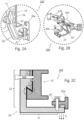
FIGs 2A-2C , thechassis adapter 20 comprises afirst arm 21 configured to at least partially support thecomponent 30, and asecond arm 22 comprising acontact face 23, fixation means 50a is configured to secure a form lock of thechassis adapter 20 onto thechassis 10. In one embodiment, thefirst arm 21 transfers into thesecond arm 22 at an angle smaller than π radians, i.e. smaller than ninety degrees, preferably in a range from forty five up to one hundred and twenty degrees. In another or further embodiment, thesecond arm 22 comprises afirst profile 24. In yet another or further embodiment, e.g., as shown inFIG 2C orFIGs 3A-C , thechassis 10 comprises asecond profile 11 shaped correspondingly to thefirst profile 24 with an edge upstanding in a direction opposite to gravitational forces G acting on thechassis 10. In other or further embodiments, thechassis adapter 20 is configured to mount thecomponent 30 onto thechassis 10 by providing thefirst arm 21 at least partially under thecomponent 30, and hooking thefirst profile 24 of thesecond arm 22 into thesecond profile 11 of thechassis 10, thereby engaging thecontact face 23 by a compressional force C, caused by the weight of thecomponent 30 through a torsional moment M around an edge of thesecond profile 11. - In some embodiments, e.g. as shown in
FIG 2C , thesecond arm 22 of thechassis adapter 20 is hooked by thefirst profile 24 to thesecond profile 11 arranged on a first side of a chassis beam. In another or further embodiment, thesecond arm 22 transfers into thefirst arm 21 towards a second side of the chassis beam for providing a torsional moment M around the edge. - Preferably, the
contact face 23 is secured to thechassis 10 by a fixation means 50a, e.g., a bolt, a plug, a rivet, a snap-lock or other type of a fixation means to prevent vibrating loose, for instance during a bumpy ride. In one embodiment, the fixation means 50a are realized by a combination of measures without applying a further securing device element like a bolt or a plug in thesecond arm 22. For example, two attachment means 50b arranged at two opposing sides of thecomponent 30 can be used to fixate twoseparate chassis adapters 20 in the lateral direction and a form-lockingfirst profile 24, protruding into thechassis 10 material in both the vertical direction and also at least partly in the lateral direction as shown inFIG 3B , fixates therespective chassis adapter 20 in the vertical and horizontal directions, thereby securing the respective form locks of the twoseparate chassis adapters 20 on thechassis 10. - Typically, the amount of engaging of the
contact face 23 to thechassis 10 is proportional to the compression forces C acting on thecontact face 23, which are proportional to gravitational forces G acting on thechassis adapter 20 and/or thecomponent 30 supported by thechassis adapter 20. In some embodiments, e.g., as shown inFIG 2C , the compression forces C are acting on thecontact face 23 above a fulcrum F formed by the edge of thesecond profile 11 around which thechassis adapter 20 can exert the torsional moment M. -
FIGs 3A-C illustrate various embodiments of a chassis adapter. In some embodiments, thechassis 10 comprises afirst profile 24 provided with a shape configured to self-align and/or form-lock with asecond profile 11 by means of a movement M around a fulcrum F (as indicated inFIG 2C ) formed by hooking thefirst profile 24 of thesecond arm 22 into thesecond profile 11 of thechassis 10. Typically, the movement M is supported by gravitational forces G acting on thechassis adapter 20 and/or acomponent 30 residing on thechassis adapter 20. InFIG 2C and3A thefirst profile 24 and the correspondingsecond profile 11 are shaped by a wedge-shaped triangle geometry. In one embodiment, the angle between the wedge-shapedfirst profile 24 and thesecond arm 22 is in a range between zero and ninety degrees, preferably in a range from twenty up to seventy degrees. InFIG 3B and 3C thefirst profile 24 and itssecond profile 11 are shaped by a ball-shaped cross section geometry. InFIG 3B the ball-shaped geometry protrudes (or hooks) into thechassis 10 material in both the vertical direction and also at least partly in the lateral direction for the purpose of reducing risk of vibrating loose during a bumpy ride. In other or further embodiments, e.g. as shown inFIGs 2A and3A-C , is thefirst profile 24 of thesecond arm 22 embraced in a portion of thechassis 10. - Preferably, the
chassis 10 comprises a plurality of second profiles configured to receive thefirst profile 24 of achassis adapter 20 at a plurality of distinct positions. In one embodiment, thechassis 10 comprises at least onechassis adapter 20 provided on each of at least two opposing sides of thechassis 10 and at least one anotherchassis adapter 20 provided on across member 10d laterally extending across the opposing sides of thechassis 10, e.g., at a location of the rear axle and below a fifth wheel coupling plate. - In some embodiments, the
chassis adapter 20 is provided with an L-shape. In one embodiment, e.g., as shown inFIG 4A , thechassis adapter 20, which is connected to thecross member 10d at the rear Rv of thevehicle 100, comprises areinforcement structure 20r provided on at least one side of thechassis adapter 20, thereby reinforcing the connection between thesecond arm 22 and thefirst arm 21 of thechassis adapter 20 to increase a load capacity of thechassis adapter 20 by at least a factor of two. In one embodiment, thereinforcement structure 20r has a form of a plate. Typically, thechassis adapter 20 has a load capacity of at least ten, preferably at least hundred times more than the static gravitational load on thechassis adapter 20. In one embodiment, thechassis adapter 20 provided with thereinforcement structure 20r has a static load capacity of at least three hundred kilograms and a dynamic load capacity, e.g., during a bumpy ride, of at least a factor of two, preferably a factor in a range from five to ten higher as compared to the static load capacity. In another or further embodiment, thechassis adapter 20 provided with a reinforcement structure is arranged on across member 10d at the rear Rv of thevehicle 100. In yet further embodiments, thechassis adapter 20 provided with thereinforcement structure 20r carries a load of at least a factor of two larger as compared to the load carried by thechassis adapter 20 without thereinforcement structure 20r. Preferably, at least onechassis adapter 20 is arranged at the front Fv of the vehicle on each of theelongated chassis beams chassis adapter 20 is arranged on thecross member 10d at the rear Rv of thevehicle 100. Alternatively or in addition, thechassis adapter 20 deforms by less than half of a millimeter when exposed to a load capacity of at least one thousand kilograms. - In other or further embodiments, e.g., as shown in
FIG 4A and FIG 4B , thesecond profile 11 is comprised on abracket 60 arranged on thechassis 10. In one embodiment, thefirst profile 24 of thechassis adapter 20 is configured by shape with limited compact dimensions in height and width to be accurately positioned (also in longitudinal direction) and/or hooked into a correspondingsecond profile 11 hole forming part of thebracket 60. This eases the mounting operation during assembly and contributes to a simple and compact design of the chassis adapter 20 (separately shown inFIG 4A and 4B ).FIG 2A illustrates a cross sectional view of the bracket system as illustrated inFIG 4B wherein the samefirst profile 24 and correspondingsecond profile 11 cut-out hole is visible. Following this design of a first profile with limited dimensions to be hooked into a corresponding second profile hole in bracket 60 (or directly in chassis 10), the fixation means 50a can be realized without the need for an additional securing bolt in thesecond arm 22 of thechassis adapter 20. As explained before in the case of an embodiment without a bracket, the fixation means 50a can be realized by a combination of measures, advantageously by interconnecting two opposingchassis adapters 20 via thecomponent 30 using the respective attachment means 50b and activating the form-locking mechanism by gravitational forces pulling on therespective chassis adapter 20. - Alternatively or in addition, the
bracket 60 at the front Fv of thevehicle 100 shown inFIG 4B comprises mounting means for mounting ahydrogen storage system 70 onto saidbracket 60. In one embodiment, thehydrogen storage system 70 comprises a frame carrying one or more hydrogen vessels. In another or further embodiment, the frame of the hydrogen storage system provides a stable (rigid bridge member) interconnection between the twoelongated chassis beams FIG 1B andFIG 4C . In another or further embodiment, thebracket 60 is provided with an additional connection to a so-called cabin bridge (not shown), being construed by a straight or curved cross beam and facilitating further mounting points for the components (springs and dampers) of the cabin suspension, which also interconnects the two elongated chassis beams at the back of the cabin and thus forms an additional chassis cross member. In yet further embodiments, thebracket 60 provides multiple functionality of facilitating mounting of the component 30 (e.g. fuel cell box) via the plurality of thechassis adapters 20 onto the chassis, and a connection of a front wheel mudguard support, a front axle leaf spring, and/or a hydrogen tank on a side of thechassis 10. - Preferably, the attachment means 50b of the
chassis adapter 20 to thecomponent 30 are configured to be accessible from above, e.g., as shown inFIG 4C for reasons of standardized assembly operations in the vehicle manufacturing plant with the objective of reduced cycle times and ergonomic handling of the tool that are being used during the assembly of thevehicle 100. - In yet further embodiments, the
component 30 is provided with a plurality ofmount parts component 30 and thechassis adapter 20, e.g., on a sidewall of thecomponent 30. In one embodiment, the plurality ofmount parts respective mount part first arm 21 of thechassis adapter 20, thereby mounting thecomponent 30 to thechassis 10, e.g., as illustrated inFIG 4C . In another or further embodiment, at least one of the plurality ofmount parts bushing 40 for guiding the attachment means 50b to thefirst arm 21 of thechassis adapter 20. In one embodiment, thebushing 40 comprises an elastomeric material that transmits the forces between thechassis adapter 20 and themount parts chassis 10, e.g., in the case of the three-point mounting of thecomponent 30 illustrated inFIG 1B and4C . Preferably, the attachment means 50b and/or thebushing 40 is accessible from above via a space in-between thecomponent 30 and thechassis 10. - In other or further embodiments, the
chassis 10 comprises a pair ofelongated chassis beams vehicle 100. In one embodiment, thechassis 10 comprises acentral cross member 10c laterally extending across thechassis beams component 30 is provided between thechassis beams cross member 10c. Preferably, thecomponent 30 is mounted in the storage space by at least onechassis adapter 20. In one embodiment, a plurality of chassis adapters mounted on theelongated chassis beams cross member 10d, e.g., different axial and/or lateral stiffness or torsional properties which are provided by the elastomeric material comprised in thebushing 40. For example, thebushing 40 on thecross member 10d provided at a rear R of avehicle 100 has a lower stiffness than the plurality of chassis adapter bushings on the elongated beams at the front Fv of thevehicle 100, thereby accommodating for torsional and/or vertical vibrations of thecomponent 30 at the rear Rv of thevehicle 100. - In yet further embodiments, the
component 30 is provided with an inverted T-shape or a L-shape cross section extending into said storage space. In one embodiment, thecomponent 30 is a fuel cell configured to provide electric energy to thevehicle 100. - In some embodiments, e.g., as illustrated in
FIGs 1B and2C , a method of mounting 200 acomponent 30 onto a chassis of avehicle 100 using thechassis 10 comprises providing a lifting support L to acomponent 30 from below into thechassis 10, hooking thefirst profile 24 of thesecond arm 22 into thesecond profile 11 of thechassis 10, thereby engaging by form-locking and compression forces C thecontact face 23 of thesecond arm 22 to thechassis 10 and attaching thecomponent 30 to thefirst arm 21. Typically, removing the lifting support L provides residing of thecomponent 30 on thefirst arm 21 of at least onechassis adapter 20. This vertical lifting and dropping method of mounting thecomponent 30 provides the technical effect of avoiding packaging clearance penalties that are associated with simultaneous horizontal maneuvering of the component during the assembly operation. Consequently, the assembly process is simplified and the corresponding clearance penalty related to associated horizontal motions are minimized. Since said vertical lifting and dropping method enables mounting ofcomponent 30 below acentral cross member 10c, the correspondingcutout space 31 shown inFIG 1B can be reduced to a minimum amount as clearance penalties related to the associated horizontal motions are advantageously avoided, as a result of which more space under the chassis can be utilized for mounting thecomponent 30. - For the purpose of clarity and a concise description, features are described herein as part of the same or separate embodiments, however, it will be appreciated that the scope of the invention may include embodiments having combinations of all or some of the features described.
- In interpreting the appended claims, it should be understood that the word "comprising" does not exclude the presence of other elements or acts than those listed in a given claim; the word "a" or "an" preceding an element does not exclude the presence of a plurality of such elements; any reference signs in the claims do not limit their scope; several "means" may be represented by the same or different item(s) or implemented structure or function; any of the disclosed devices or portions thereof may be combined together or separated into further portions unless specifically stated otherwise. Where one claim refers to another claim, this may indicate synergetic advantage achieved by the combination of their respective features. But the mere fact that certain measures are recited in mutually different claims does not indicate that a combination of these measures cannot also be used to advantage. The present embodiments may thus include all working combinations of the claims wherein each claim can in principle refer to any preceding claim unless clearly excluded by context.
Claims (19)
- A chassis (10) of a vehicle (100) provided with at least one chassis adapter (20) for mounting (200) a component (30) onto the chassis (10),wherein the chassis adapter (20) comprises a first arm (21) configured to at least partially support the component (30), and a second arm (22) comprising a contact face (23) and a fixation means (50a) configured to secure the chassis adapter (20) onto the chassis (10);wherein the second arm (22) comprises a first profile (24);wherein the chassis (10) comprises a second profile (11) shaped correspondingly to the first profile (24) with an edge upstanding in a direction opposite to gravitational forces (G) acting on the chassis (10);wherein the chassis adapter (20) is configured to mount (200) the component (30) onto the chassis (10) bypositioning the first arm (21) at least partially under the component (30), andhooking the first profile (24) of the second arm (22) onto the edge of the second profile (11), thereby engaging the contact face (23) of the second arm (22) to the chassis (10) and attaching the component (30) to the first arm (21), wherein the fixation means (50a) prevents displacement of the first profile (24) from the second profile (11).
- The chassis (10) according to the preceding claim,wherein the first profile (24) is provided with a shape configured to self-align with the second profile (11) by means of a movement (M) around a fulcrum (F) formed by hooking the first profile (24) of the second arm (22) into the second profile (11) of the chassis (10),wherein the movement (M) is supported by gravitational forces (G) acting on the chassis adapter (20) and/or a component (30) residing on the chassis adapter (20).
- The chassis (10) according to any of the preceding claims, wherein the chassis (10) comprises a plurality of second profiles configured to receive the first profile (24) of a chassis adapter (20) at a plurality of distinct positions.
- The chassis (10) according to any of the preceding claims, wherein the chassis adapter (20) has a load capacity of at least five, preferably at least ten times more than the static gravitational load on the component (30).
- The chassis (10) according to any of the preceding claims, wherein the chassis adapter (20) is provided with a first profile (24) comprising a wedge-shaped geometry.
- The chassis (10) according to any of the preceding claims, wherein one from the group consisting of the first profile (24) and the second profile (11) has limited width and height with respect to the dimensions of the other member from the group, thereby configured to prevent displacements relative to each other.
- The chassis (10) according to any of the preceding claims, wherein the fixation means (50a) is formed by an interconnection via attachment means (50b) of a component (30) arranged between two opposing chassis adapters (20) and/or by a securing bolt.
- The chassis (10) according to any of the preceding claims, wherein the chassis adapter (20) is provided with an L-shape.
- The chassis (10) according to any of the preceding claims, wherein the chassis adapter (20) comprises a reinforcement structure (20r) provided on at least one side of the chassis adapter (20), thereby reinforcing the connection between the second arm (22) and the first arm (21) of the chassis adapter (20) to increase stiffness and load capacity of the chassis adapter (20) by at least a factor of two.
- The chassis (10) according to any of the preceding claims, wherein the second profile (11) is comprised on a bracket (60) that is arranged on a beam member or a cross beam member of the chassis (10).
- The chassis (10) according to claim 10, wherein the bracket (60) is arranged in a close proximity of a cross beam member (10c) and/or a rigid bridge member (70).
- The chassis (10) according to any of the preceding claims,wherein the component (30) comprises a plurality of mount parts (30a, 30b) arranged between the component (30) and the chassis adapter (20);wherein the plurality of mount parts (30a, 30b) comprises an attachment means (50b) configured to attach the respective mount part (30a, 30b) to the first arm (21) of the chassis adapter (20), thereby mounting the component (30) to the chassis (10).
- The chassis (10) according to the preceding claim, wherein at least one of the plurality of mount parts (30a, 30b) is provided with a bushing (40) comprising an elastomeric material.
- The chassis (10) according to the preceding claim, wherein the bushing (40) is accessible by tooling from above the chassis (10) via a space in-between the component (30) and the chassis (10).
- The chassis (10) according to any of the preceding claims, wherein the chassis (10) comprisesa pair of elongated chassis beams (10a, 10b) extending along the length of the vehicle (100),a cross member (10c) laterally extending across the chassis beams (10a, 10b), wherein a storage space configured to receive a component (30) is provided between the chassis beams (10a, 10b) extending underneath the cross member (10c);wherein the component (30) is mounted in the storage space by at least one chassis adapter (20).
- The chassis (10) according to the preceding claim, wherein a three point connection is formed by at least two chassis adapters (20) provided on the pair of elongated chassis beams (10a, 10b) on two opposing sides of the chassis (10) at the front (Fv) of the component (30) and by at least a third chassis adapter (20) provided at the rear (Rv) of the component (30) on a cross-member (10d) laterally extending across the pair of elongated chassis beams (10a, 10b).
- The chassis (10) according to claim 10, wherein the component (30) is provided with an inverted T-shape or a L-shape cross section extending into said storage space.
- The chassis (10) according to any of the preceding claims, wherein the component (30) is a fuel cell system module or a battery module configured to provide electric energy to the vehicle (100).
- A method of mounting (200) a component (30) onto a chassis of a vehicle (100) using the chassis (10) according to any of the preceding claims, the method comprisingproviding a lifting support (L) to a component (30) from below into the chassis (10),hooking the first profile (24) of the second arm (22) onto the edge of second profile (11) of the chassis (10), thereby engaging the contact face (23) of the second arm (22) to the chassis (10) and attaching the component (30) to the first arm (21).removing the lifting support (L) and thereby residing the component (30) on the first arm (21) of at least one chassis adapter (20), andpreventing displacement of the first profile from the second profile by a fixation means (50a).
Applications Claiming Priority (1)
| Application Number | Priority Date | Filing Date | Title |
|---|---|---|---|
| NL2036135A NL2036135B1 (en) | 2023-10-26 | 2023-10-26 | Vehicle chassis with an adapter for mounting a component |
Publications (1)
| Publication Number | Publication Date |
|---|---|
| EP4545385A1 true EP4545385A1 (en) | 2025-04-30 |
Family
ID=90810209
Family Applications (1)
| Application Number | Title | Priority Date | Filing Date |
|---|---|---|---|
| EP24208768.2A Pending EP4545385A1 (en) | 2023-10-26 | 2024-10-24 | Vehicle chassis with an adapter for mounting a component |
Country Status (2)
| Country | Link |
|---|---|
| EP (1) | EP4545385A1 (en) |
| NL (1) | NL2036135B1 (en) |
Citations (3)
| Publication number | Priority date | Publication date | Assignee | Title |
|---|---|---|---|---|
| WO2018141513A1 (en) * | 2017-01-31 | 2018-08-09 | Volvo Truck Corporation | A fastening element |
| WO2020041630A1 (en) * | 2018-08-24 | 2020-02-27 | Hexagon Purus North America Holdings Inc. | Battery system for heavy duty vehicles |
| EP3988359A1 (en) * | 2020-10-26 | 2022-04-27 | Volvo Truck Corporation | An energy storage mounting system |
-
2023
- 2023-10-26 NL NL2036135A patent/NL2036135B1/en active
-
2024
- 2024-10-24 EP EP24208768.2A patent/EP4545385A1/en active Pending
Patent Citations (3)
| Publication number | Priority date | Publication date | Assignee | Title |
|---|---|---|---|---|
| WO2018141513A1 (en) * | 2017-01-31 | 2018-08-09 | Volvo Truck Corporation | A fastening element |
| WO2020041630A1 (en) * | 2018-08-24 | 2020-02-27 | Hexagon Purus North America Holdings Inc. | Battery system for heavy duty vehicles |
| EP3988359A1 (en) * | 2020-10-26 | 2022-04-27 | Volvo Truck Corporation | An energy storage mounting system |
Also Published As
| Publication number | Publication date |
|---|---|
| NL2036135B1 (en) | 2025-05-12 |
Similar Documents
| Publication | Publication Date | Title |
|---|---|---|
| EP3693201B1 (en) | Fuel cell vehicle | |
| EP4054879B1 (en) | A battery box arrangement | |
| EP2768719B1 (en) | Rear-wheel drive, plug-in hybrid electric vehicle modular subframe assembly and method | |
| EP4112391A1 (en) | A chassis assembly for a vehicle | |
| CN108290609B (en) | Rear axle subframe and motor vehicle with such rear axle subframe | |
| EP3007962B1 (en) | Cross-member and method for mounting a component to a vehicle frame beam | |
| US20250229618A1 (en) | Bracket assembly for attaching component to vehicle | |
| US11014458B2 (en) | Die-cast aluminum bracket | |
| KR20190004338A (en) | vehicle | |
| KR102587989B1 (en) | Hydrogen tank mounting unit for vehicle | |
| WO2023200870A1 (en) | Mounting assembly attaching power supply to vehicle | |
| US20240359743A1 (en) | Support system for an alternative fuel heavy vehicle | |
| US20220135135A1 (en) | Subframe for vehicle | |
| NL2036135B1 (en) | Vehicle chassis with an adapter for mounting a component | |
| CN103507799A (en) | Supporting structure for reserve tank | |
| KR20220105435A (en) | Running bare chassis for a low-floor bus and manufacturing method thereof | |
| US12233695B1 (en) | Electric vehicle having motor shield | |
| CN117863857A (en) | Coupling device and apparatus for motor vehicle, motor vehicle and coupling method | |
| CN219056385U (en) | Frame and chassis thereof | |
| US6820884B2 (en) | Integrated axle adaptor and spring seat for a vehicle suspension system | |
| EP4737154A1 (en) | A vehicle battery pack mounting bracket | |
| CN107176030B (en) | The fuel gas cylinder mounting structure of vehicle body | |
| CN214336849U (en) | A battery installation structure and vehicle | |
| CN113602355A (en) | Vehicle chassis frame | |
| CN222756411U (en) | Suspension mechanism and off-highway mining dump truck |
Legal Events
| Date | Code | Title | Description |
|---|---|---|---|
| PUAI | Public reference made under article 153(3) epc to a published international application that has entered the european phase |
Free format text: ORIGINAL CODE: 0009012 |
|
| STAA | Information on the status of an ep patent application or granted ep patent |
Free format text: STATUS: THE APPLICATION HAS BEEN PUBLISHED |
|
| AK | Designated contracting states |
Kind code of ref document: A1 Designated state(s): AL AT BE BG CH CY CZ DE DK EE ES FI FR GB GR HR HU IE IS IT LI LT LU LV MC ME MK MT NL NO PL PT RO RS SE SI SK SM TR |
|
| STAA | Information on the status of an ep patent application or granted ep patent |
Free format text: STATUS: REQUEST FOR EXAMINATION WAS MADE |
|
| 17P | Request for examination filed |
Effective date: 20250703 |