EP4545344A1 - Method and apparatus for distributing torques of electric drive axles - Google Patents

Method and apparatus for distributing torques of electric drive axles Download PDF

Info

Publication number
EP4545344A1
EP4545344A1 EP24204132.5A EP24204132A EP4545344A1 EP 4545344 A1 EP4545344 A1 EP 4545344A1 EP 24204132 A EP24204132 A EP 24204132A EP 4545344 A1 EP4545344 A1 EP 4545344A1
Authority
EP
European Patent Office
Prior art keywords
torque
electric drive
wheel end
drive axle
rmax
Prior art date
Legal status (The legal status is an assumption and is not a legal conclusion. Google has not performed a legal analysis and makes no representation as to the accuracy of the status listed.)
Pending
Application number
EP24204132.5A
Other languages
German (de)
French (fr)
Inventor
Hantian ZHANG
Hailiang Liu
Current Assignee (The listed assignees may be inaccurate. Google has not performed a legal analysis and makes no representation or warranty as to the accuracy of the list.)
Robert Bosch GmbH
Original Assignee
Robert Bosch GmbH
Priority date (The priority date is an assumption and is not a legal conclusion. Google has not performed a legal analysis and makes no representation as to the accuracy of the date listed.)
Filing date
Publication date
Application filed by Robert Bosch GmbH filed Critical Robert Bosch GmbH
Publication of EP4545344A1 publication Critical patent/EP4545344A1/en
Pending legal-status Critical Current

Links

Images

Classifications

    • BPERFORMING OPERATIONS; TRANSPORTING
    • B60VEHICLES IN GENERAL
    • B60LPROPULSION OF ELECTRICALLY-PROPELLED VEHICLES; SUPPLYING ELECTRIC POWER FOR AUXILIARY EQUIPMENT OF ELECTRICALLY-PROPELLED VEHICLES; ELECTRODYNAMIC BRAKE SYSTEMS FOR VEHICLES IN GENERAL; MAGNETIC SUSPENSION OR LEVITATION FOR VEHICLES; MONITORING OPERATING VARIABLES OF ELECTRICALLY-PROPELLED VEHICLES; ELECTRIC SAFETY DEVICES FOR ELECTRICALLY-PROPELLED VEHICLES
    • B60L15/00Methods, circuits, or devices for controlling the traction-motor speed of electrically-propelled vehicles
    • B60L15/20Methods, circuits, or devices for controlling the traction-motor speed of electrically-propelled vehicles for control of the vehicle or its driving motor to achieve a desired performance, e.g. speed, torque, programmed variation of speed
    • BPERFORMING OPERATIONS; TRANSPORTING
    • B60VEHICLES IN GENERAL
    • B60KARRANGEMENT OR MOUNTING OF PROPULSION UNITS OR OF TRANSMISSIONS IN VEHICLES; ARRANGEMENT OR MOUNTING OF PLURAL DIVERSE PRIME-MOVERS IN VEHICLES; AUXILIARY DRIVES FOR VEHICLES; INSTRUMENTATION OR DASHBOARDS FOR VEHICLES; ARRANGEMENTS IN CONNECTION WITH COOLING, AIR INTAKE, GAS EXHAUST OR FUEL SUPPLY OF PROPULSION UNITS IN VEHICLES
    • B60K17/00Arrangement or mounting of transmissions in vehicles
    • B60K17/34Arrangement or mounting of transmissions in vehicles for driving both front and rear wheels, e.g. four wheel drive vehicles
    • B60K17/356Arrangement or mounting of transmissions in vehicles for driving both front and rear wheels, e.g. four wheel drive vehicles having fluid or electric motor, for driving one or more wheels
    • BPERFORMING OPERATIONS; TRANSPORTING
    • B60VEHICLES IN GENERAL
    • B60LPROPULSION OF ELECTRICALLY-PROPELLED VEHICLES; SUPPLYING ELECTRIC POWER FOR AUXILIARY EQUIPMENT OF ELECTRICALLY-PROPELLED VEHICLES; ELECTRODYNAMIC BRAKE SYSTEMS FOR VEHICLES IN GENERAL; MAGNETIC SUSPENSION OR LEVITATION FOR VEHICLES; MONITORING OPERATING VARIABLES OF ELECTRICALLY-PROPELLED VEHICLES; ELECTRIC SAFETY DEVICES FOR ELECTRICALLY-PROPELLED VEHICLES
    • B60L15/00Methods, circuits, or devices for controlling the traction-motor speed of electrically-propelled vehicles
    • B60L15/20Methods, circuits, or devices for controlling the traction-motor speed of electrically-propelled vehicles for control of the vehicle or its driving motor to achieve a desired performance, e.g. speed, torque, programmed variation of speed
    • B60L15/2045Methods, circuits, or devices for controlling the traction-motor speed of electrically-propelled vehicles for control of the vehicle or its driving motor to achieve a desired performance, e.g. speed, torque, programmed variation of speed for optimising the use of energy
    • BPERFORMING OPERATIONS; TRANSPORTING
    • B60VEHICLES IN GENERAL
    • B60WCONJOINT CONTROL OF VEHICLE SUB-UNITS OF DIFFERENT TYPE OR DIFFERENT FUNCTION; CONTROL SYSTEMS SPECIALLY ADAPTED FOR HYBRID VEHICLES; ROAD VEHICLE DRIVE CONTROL SYSTEMS FOR PURPOSES NOT RELATED TO THE CONTROL OF A PARTICULAR SUB-UNIT
    • B60W30/00Purposes of road vehicle drive control systems not related to the control of a particular sub-unit, e.g. of systems using conjoint control of vehicle sub-units
    • B60W30/18Propelling the vehicle
    • BPERFORMING OPERATIONS; TRANSPORTING
    • B60VEHICLES IN GENERAL
    • B60LPROPULSION OF ELECTRICALLY-PROPELLED VEHICLES; SUPPLYING ELECTRIC POWER FOR AUXILIARY EQUIPMENT OF ELECTRICALLY-PROPELLED VEHICLES; ELECTRODYNAMIC BRAKE SYSTEMS FOR VEHICLES IN GENERAL; MAGNETIC SUSPENSION OR LEVITATION FOR VEHICLES; MONITORING OPERATING VARIABLES OF ELECTRICALLY-PROPELLED VEHICLES; ELECTRIC SAFETY DEVICES FOR ELECTRICALLY-PROPELLED VEHICLES
    • B60L2220/00Electrical machine types; Structures or applications thereof
    • B60L2220/40Electrical machine applications
    • B60L2220/42Electrical machine applications with use of more than one motor
    • BPERFORMING OPERATIONS; TRANSPORTING
    • B60VEHICLES IN GENERAL
    • B60LPROPULSION OF ELECTRICALLY-PROPELLED VEHICLES; SUPPLYING ELECTRIC POWER FOR AUXILIARY EQUIPMENT OF ELECTRICALLY-PROPELLED VEHICLES; ELECTRODYNAMIC BRAKE SYSTEMS FOR VEHICLES IN GENERAL; MAGNETIC SUSPENSION OR LEVITATION FOR VEHICLES; MONITORING OPERATING VARIABLES OF ELECTRICALLY-PROPELLED VEHICLES; ELECTRIC SAFETY DEVICES FOR ELECTRICALLY-PROPELLED VEHICLES
    • B60L2240/00Control parameters of input or output; Target parameters
    • B60L2240/40Drive Train control parameters
    • B60L2240/42Drive Train control parameters related to electric machines
    • B60L2240/423Torque
    • BPERFORMING OPERATIONS; TRANSPORTING
    • B60VEHICLES IN GENERAL
    • B60LPROPULSION OF ELECTRICALLY-PROPELLED VEHICLES; SUPPLYING ELECTRIC POWER FOR AUXILIARY EQUIPMENT OF ELECTRICALLY-PROPELLED VEHICLES; ELECTRODYNAMIC BRAKE SYSTEMS FOR VEHICLES IN GENERAL; MAGNETIC SUSPENSION OR LEVITATION FOR VEHICLES; MONITORING OPERATING VARIABLES OF ELECTRICALLY-PROPELLED VEHICLES; ELECTRIC SAFETY DEVICES FOR ELECTRICALLY-PROPELLED VEHICLES
    • B60L2240/00Control parameters of input or output; Target parameters
    • B60L2240/40Drive Train control parameters
    • B60L2240/46Drive Train control parameters related to wheels
    • B60L2240/463Torque
    • BPERFORMING OPERATIONS; TRANSPORTING
    • B60VEHICLES IN GENERAL
    • B60LPROPULSION OF ELECTRICALLY-PROPELLED VEHICLES; SUPPLYING ELECTRIC POWER FOR AUXILIARY EQUIPMENT OF ELECTRICALLY-PROPELLED VEHICLES; ELECTRODYNAMIC BRAKE SYSTEMS FOR VEHICLES IN GENERAL; MAGNETIC SUSPENSION OR LEVITATION FOR VEHICLES; MONITORING OPERATING VARIABLES OF ELECTRICALLY-PROPELLED VEHICLES; ELECTRIC SAFETY DEVICES FOR ELECTRICALLY-PROPELLED VEHICLES
    • B60L2260/00Operating Modes
    • B60L2260/20Drive modes; Transition between modes
    • B60L2260/28Four wheel or all wheel drive
    • BPERFORMING OPERATIONS; TRANSPORTING
    • B60VEHICLES IN GENERAL
    • B60WCONJOINT CONTROL OF VEHICLE SUB-UNITS OF DIFFERENT TYPE OR DIFFERENT FUNCTION; CONTROL SYSTEMS SPECIALLY ADAPTED FOR HYBRID VEHICLES; ROAD VEHICLE DRIVE CONTROL SYSTEMS FOR PURPOSES NOT RELATED TO THE CONTROL OF A PARTICULAR SUB-UNIT
    • B60W2710/00Output or target parameters relating to a particular sub-units
    • B60W2710/08Electric propulsion units
    • B60W2710/083Torque
    • BPERFORMING OPERATIONS; TRANSPORTING
    • B60VEHICLES IN GENERAL
    • B60WCONJOINT CONTROL OF VEHICLE SUB-UNITS OF DIFFERENT TYPE OR DIFFERENT FUNCTION; CONTROL SYSTEMS SPECIALLY ADAPTED FOR HYBRID VEHICLES; ROAD VEHICLE DRIVE CONTROL SYSTEMS FOR PURPOSES NOT RELATED TO THE CONTROL OF A PARTICULAR SUB-UNIT
    • B60W2720/00Output or target parameters relating to overall vehicle dynamics
    • B60W2720/40Torque distribution
    • B60W2720/403Torque distribution between front and rear axle

Definitions

  • the present application relates to the field of electric drive axle torque control, and more particularly relates to a method and apparatus for distributing torques of electric drive axles, a computer-readable storage medium, a computer program product, and an electric drive axle system.
  • An electric drive axle also known as an electric bridge, is a type of drive axle, its power device is adjusted from driving by an original internal combustion engine to driving by a motor, and most of electric drive axles integrate motors onto axles for implementing integration, high efficiency and other functions.
  • a heavy truck with dule electric drive axles and four drives is taken as an example. Since there are two electric drive axles and each electric drive axle has four gears, maximum carrying torque values of the two electric drive axles may be different. In an existing solution, torques are generally distributed equally to the two axles, but because the efficiency and the maximum carrying torque values of the two electric drive axles are different, the most economical torque combination (or the optimum economic torque ratio) cannot be obtained by distributing the torques equally to minimize power consumption.
  • a method for distributing torques of electric drive axles comprising: receiving a wheel end demand torque; determining a corresponding energy efficiency calculation state and all torque combinations based on the wheel end demand torque and limit values of the electric drive axles; calculating corresponding power using efficiency of the electric drive axles for each of all torque combinations, respectively; and screening a torque combination corresponding to the maximum power to determine the most economical torque combination.
  • calculating the corresponding power using the efficiency of the electric drive axles for each of all torque combinations respectively comprises: determining a first efficiency matrix corresponding to a torque matrix of the front electric drive axle; determining a second efficiency matrix corresponding to a torque matrix of the rear electric drive axle; calculating a first power matrix of the front electric drive axle and a second power matrix of the rear electric drive axle based on the first efficiency matrix and the second efficiency matrix, respectively; and summing the first power matrix with the second efficiency matrix to obtain a total power matrix.
  • screening the torque combination corresponding to the maximum power to determine the most economical torque combination comprises: screening the maximum power from the total power matrix; and determining, based on the maximum power, a first target torque and a first target gear of the front electric drive axle and a second target torque and a second target gear of the rear electric drive axle that are finally distributed.
  • an apparatus for distributing torques of electric drive axles comprising: a receiving device for receiving a wheel end demand torque; a determining device for determining a corresponding energy efficiency calculation state and all torque combinations based on the wheel end demand torque and limit values of the electric drive axles; a calculating device for calculating corresponding power using efficiency of the electric drive axles for each of all torque combinations, respectively; and a screening device for screening a torque combination corresponding to the maximum power to determine the most economical torque combination.
  • the calculating device is configured to: determine a first efficiency matrix corresponding to a torque matrix of the front electric drive axle; determine a second efficiency matrix corresponding to a torque matrix of the rear electric drive axle; calculate a first power matrix of the front electric drive axle and a second power matrix of the rear electric drive axle based on the first efficiency matrix and the second efficiency matrix, respectively; and sum the first power matrix with the second efficiency matrix to obtain a total power matrix.
  • the screening device is configured to: screen the maximum power from the total power matrix; and determine, based on the maximum power, a first target torque and a first target gear of the front electric drive axle and a second target torque and a second target gear of the rear electric drive axle that are finally distributed.
  • a computer-readable storage medium comprises instructions, and the instructions, when running, perform the method as described above.
  • a computer program product which comprises a computer program, and the computer program, when executed by the processor, implements the method as described above.
  • an electric drive axle system comprising: a front electric drive axle comprising the apparatus for distributing torques of electric drive axles as described above, wherein the front electric drive axle is configured to receive a wheel end demand torque from a vehicle control unit VCU; and a rear electric drive axle for being in communication with the front electric drive axle to perform a target torque and a target gear distributed by the front electric drive axle.
  • the solution of distributing torques of electric drive axles determines the optimum torque distribution ratio in an economic mode by the wheel end demand torque, the limit values of the electric drive axles, and the efficiency of the electric drive axles.
  • the solution of distributing torques of electric drive axles according to an example of the present application determines the corresponding energy efficiency calculation state and all torque combinations based on the wheel end demand torque and the limit values of the electric drive axles, calculates the corresponding power using the efficiency of the electric drive axles for each of all torque combinations, and finally screens the torque combination corresponding to the maximum power to determine the most economical torque combination.
  • the solution of distributing torques of electric drive axles as described above can obtain the most economical torque combination such that the power consumption is minimal.
  • FIG. 1 shows a flow diagram of a method 1000 for distributing torques of electric drive axles according to one example of the present application.
  • the method 1000 for distributing torques of electric drive axles comprises the following steps:
  • step S120 the corresponding energy efficiency calculation state and all torque combinations are determined based on the wheel end demand torque and the limit values of the electric drive axles (e.g., the front electric drive axle wheel end limit torque Tq Fmax and the rear electric drive axle wheel end limit torque Tq Rmax ).
  • the torque matrix of the front electric drive axle is [0, Tq dif *1, Tq dif *2,..., Tq dif *N1]
  • the corresponding torque matrix of the rear electric drive axle is [Tq, Tq-Tq dif *1, Tq-Tq dif *2,..., Tq-Tq dif *N1].
  • the torque combinations i.e., [the front electric drive axle torque, the rear electric drive axle torque]
  • the torque combinations comprise the following: [0,Tq], [Tq dif *1, Tq-Tq dif *1], [Tq dif *2, Tq-Tq dif *2]...[Tq dif *N1 Tq-Tq dif *N1].
  • the torque of the dual electric drive axles has the following torque distribution combinations: [0,100], [20,80], [40,60], [60,40], [80,20], [100,0].
  • the torque matrix of the front electric drive axle is [0, Tq dif *1, Tq dif *2,..., Tq dif *N2]
  • the corresponding torque matrix of the rear electric drive axle is [Tq, Tq-Tq dif *1,Tq-Tq dif *2,..., Tq-Tq dif *N2].
  • the torque combinations comprise: [0, Tq], [Tq dif *1, Tq-Tq dif *1], [Tq dif *2, Tq-Tq dif *2]...[Tq dif *N2,Tq-Tq dif *N2].
  • the torque matrix of the front electric drive axle is [Tq-Tq Rmax , Tq-Tq Rmax +Tq dif *1, Tq-Tq Rmax +Tq dif *2,..., Tq-Tq Rmax +Tq dif *N3]
  • the corresponding torque matrix of the rear electric drive axle is [Tq-(Tq-Tq Rmax ), Tq-(Tq-Tq Rmax +Tq dif *1), Tq-(Tq- Tq Rmax + Tq dif *2),..., Tq-(Tq-Tq Rmax +Tq dif *N3)].
  • the torque combinations comprise: [Tq-Tq Rmax , Tq-(Tq-Tq Rmax )], [Tq-Tq Rmax +Tq dif *1, Tq-(Tq-Tq Rmax +Tq dif *1)],[Tq-Tq Rmax +Tq dif *2, Tq-(Tq-Tq Rmax +Tq dif *2)],... , [Tq-Tq Rmax +Tq dif *N3, Tq-(Tq-Tq Rmax +Tq dif *N3)].
  • the torque matrix of the front electric drive axle is [Tq-Tq Rmax , Tq-Tq Rmax +Tq dif *1, Tq-Tq Rmax +Tq dif *2,..., Tq-Tq Rmax +Tq dif *N4]
  • the corresponding torque matrix of the rear electric drive axle is [Tq-(Tq-Tq Rmax ), Tq-(Tq-Tq Rmax +Tq dif *1), Tq- (Tq-Tq Rmax +Tq dif *2),..., Tq-(Tq-Tq Rmax +Tq dif *N4)].
  • the torque combinations comprise: [Tq-Tq Rmax , Tq-(Tq-Tq Rmax )], [Tq-Tq Rmax +Tq dif *1, Tq-(Tq-Tq Rmax +Tq dif *1)], [Tq-Tq Rmax +Tq dif *2, Tq-(Tq-Tq Rmax +Tq dif *2)],... , [Tq-Tq Rmax +Tq dif *N4, Tq-(Tq-Tq Rmax +Tq dif *N4)].
  • the torque matrix of the front electric drive axle is [Tq- Tq Rmax , Tq-Tq Rmax +Tq dif *1, Tq-Tq Rmax +Tq dif *2,..., Tq-Tq Rmax +Tq dif *N5]
  • the corresponding torque matrix of the rear electric drive axle is [Tq-(Tq-Tq Rmax ), Tq-(Tq-Tq Rmax +Tq dif *1), Tq-(Tq-Tq Rmax +Tq dif *2),..., Tq-(Tq-Tq Rmax +Tq dif *N5)].
  • the first working condition is taken as an example: if the rotational speed is not changed during a certain cycle, the first efficiency matrix corresponding to the torque matrix [0, Tq dif *1, Tq dif *2,..., Tq dif *N1] of the front electric drive axle is [ ⁇ F0 , ⁇ F1 , ⁇ F2 ,..., ⁇ FN1 ]; and the second efficiency matrix corresponding to the torque matrix [Tq, Tq-Tq dif *1,Tq-Tq dif *2,..., Tq-Tq dif *N1] of the rear electric drive axle is [ ⁇ R0 , ⁇ R1 , ⁇ R2 ,..., ⁇ RN1 ].
  • the first power matrix and the second power matrix are summed to obtain a total power matrix of [P F0 +P R0 , P F1 +P R1 , P F2 +P R2 , ..., P FN1 +P RN1 ].
  • step S140 the torque combination corresponding to the maximum power is screened to determine the most economical torque combination.
  • step S140 comprises: screening the maximum power from the total power matrix; and determining, based on the maximum power, a first target torque and a first target gear of the front electric drive axle and a second target torque and a second target gear of the rear electric drive axle that are finally distributed.
  • FIG. 2 shows a structure diagram of an apparatus 2000 for distributing torques of electric drive axles according to one example of the present application.
  • the apparatus 2000 for distributing torques of electric drive axles comprises: a receiving device 210, a determining device 220, a calculating device 230, and a screening device 240.
  • the receiving device 210 is used for receiving a wheel end demand torque; the determining device 220 is used for determining a corresponding energy efficiency calculation state and all torque combinations based on the wheel end demand torque and limit values of the electric drive axles; the calculating device 230 is used for calculating corresponding power using efficiency of the electric drive axles for each of all torque combinations, respectively; and the screening device 240 is used for screening a torque combination corresponding to the maximum power to determine the most economical torque combination.
  • the wheel end demand torque may comprise: a total wheel end demand torque Tq, a front electric drive axle wheel end demand torque Tq F , and a rear electric drive axle wheel end demand torque Tq R .
  • the determining device 220 determines the corresponding energy efficiency calculation state and all torque combinations based on the wheel end demand torque and the limit values of the electric drive axles (e.g., the front electric drive axle wheel end limit torque Tq Fmax and the rear electric drive axle wheel end limit torque Tq Rmax ).
  • the torque matrix of the front electric drive axle is determined to be [0, Tq dif *1, Tq dif *2,...
  • the torque combinations (i.e., [the front electric drive axle torque, the rear electric drive axle torque]) comprise the following: [0, Tq], [Tq dif *1, Tq-Tq dif *1], [Tq dif *2, Tq-Tq dif *2]...[Tq dif *N1, Tq-Tq dif *N1].
  • the torque of the dual electric drive axles has the following torque distribution combinations: [0,100], [20,80], [40,60], [60,40], [80,20], [100,0].
  • the torque matrix of the front electric drive axle is determined to be [0, Tq dif *1, Tq dif *2,..., Tq dif *N2], and the corresponding torque matrix of the rear electric drive axle is [Tq, Tq-Tq dif *1,Tq-Tq dif *2,..., Tq-Tq dif *N2].
  • the torque combinations comprise: [0, Tq], [Tq dif *1,Tq-Tq dif *1], [Tq dif *2, Tq-Tq dif *2]...[Tq dif *N2,Tq-Tq dif *N2].
  • the torque matrix of the front electric drive axle is determined to be [Tq-Tq Rmax , Tq-Tq Rmax +Tq dif *1, Tq-Tq Rmax +Tq dif *2,..., Tq-Tq Rmax +Tq dif *N3], and the corresponding torque matrix of the rear electric drive axle is [Tq-(Tq-Tq Rmax ), Tq-(Tq-Tq Rmax +Tq dif *1), Tq-(Tq-Tq Rmax + Tq dif *2),..., Tq-(Tq-Tq Rmax +Tq dif *N3)].
  • the torque combinations comprise: [Tq-Tq Rmax , Tq-(Tq-Tq Rmax )], [Tq-Tq Rmax +Tq dif *1,Tq-(Tq-Tq Rmax +Tq dif *1)],[Tq-Tq Rmax +Tq dif *2,Tq-(Tq-Tq Rmax +Tq dif *2)], ... ,[Tq-Tq Rmax +Tq dif *N3, Tq-(Tq-Tq Rmax +Tq dif *N3)].
  • the torque combinations comprise: [Tq-Tq Rmax , Tq-(Tq-Tq Rmax )], [Tq-Tq Rmax +Tq dif *1, Tq- (Tq-Tq Rmax +Tq dif *1)], [Tq-Tq Rmax +Tq dif *2, Tq-(Tq-Tq Rmax +Tq dif *2)],..., [Tq-Tq Rmax +Tq dif *N4, Tq-(Tq-Tq Rmax +Tq dif *N4)].
  • the torque matrix of the front electric drive axle is determined to be [Tq-Tq Rmax , Tq-Tq Rmax +Tq dif *1, Tq-Tq Rmax +Tq dif *2, ... , Tq-Tq Rmax +Tq dif *N5], and the corresponding torque matrix of the rear electric drive axle is [Tq-(Tq-Tq Rmax ), Tq-(Tq-Tq Rmax +Tq dif *1), Tq-(Tq-Tq Rmax +Tq dif *2),..., Tq-(Tq-Tq Rmax +Tq dif *N5)].
  • the torque combinations comprise: [Tq-Tq Rmax , Tq-(Tq-Tq Rmax )], [Tq-Tq Rmax +Tq dif *1, Tq-(Tq-Tq Rmax +Tq dif *1)], [Tq-Tq Rmax +Tq dif *2, Tq-(Tq-Tq Rmax +Tq dif *2)],..., [Tq-Tq Rmax +Tq dif *N5, Tq-(Tq-Tq Rmax +Tq dif *N5)].
  • the torque matrix of the front electric drive axle is determined to be [Tq Fmax ]
  • the corresponding torque matrix of the rear electric drive axle is [Tq Rmax ].
  • the torque combination is [Tq Fmax , Tq Rmax ].
  • the calculating device 230 is configured to calculate the corresponding power using the efficiency of the electric drive axles for each of all torque combinations, respectively.
  • the calculating device 230 can use For statements to calculate the power for all torque combinations for each period of working conditions at this time in a circulated mode.
  • the calculating device 230 is configured to: determine a first efficiency matrix corresponding to a torque matrix of the front electric drive axle; determine a second efficiency matrix corresponding to a torque matrix of the rear electric drive axle; calculate a first power matrix of the front electric drive axle and a second power matrix of the rear electric drive axle based on the first efficiency matrix and the second efficiency matrix, respectively; and sum the first power matrix with the second efficiency matrix to obtain a total power matrix.
  • the first working condition is taken as an example: if the rotational speed is not changed during a certain cycle, the first efficiency matrix corresponding to the torque matrix [0, Tq dif *1, Tq dif *2,..., Tq dif *N1] of the front electric drive axle is [ ⁇ F0 , ⁇ F1 , ⁇ F7 ,..., ⁇ FN1 ]; and the second efficiency matrix corresponding to the torque matrix [Tq, Tq-Tq dif *1,Tq-Tq dif *2,..., Tq-Tq dif *N1] of the rear electric drive axle is [ ⁇ R0 , ⁇ R1 , ⁇ R2 ,..., ⁇ RN1 ].
  • the first power matrix and the second power matrix are summed by the calculating device 230 to obtain a total power matrix of [P F0 +P R0 , P F1 +P R1 , P F2 +P R2 , ...,P FN1 +P RN1 ].
  • the screening device 240 is used for screening the torque combination corresponding to the maximum power to determine the most economical torque combination.
  • the screening device 240 is configured to: screen the maximum power from the total power matrix; and determine, based on the maximum power, a first target torque and a first target gear of the front electric drive axle and a second target torque and a second target gear of the rear electric drive axle that are finally distributed.
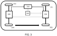
  • FIG. 3 shows a structure diagram of a vehicle comprising an electric drive axle system according to one example of the present application.
  • the electric drive axle system may comprise: a front electric drive axle 330 comprising the apparatus 2000 for distributing torques of the electric drive axles as described above, wherein the front electric drive axle 330 is configured to receive a wheel end demand torque from a vehicle control unit VCU 340; and a rear electric drive axle 320 for being in communication with the front electric drive axle 330 (for example, through a CAN bus) to perform a target torque and a target gear distributed by the front electric drive axle 330.
  • the front electric drive axle 330 is responsible for calculating the target gears and torques of the front electric drive axle and the rear electric drive axle.
  • the electric drive axle system may further comprise a battery 310 that powers the front electric drive axle 330 and the rear electric drive axle 320 under the control of the vehicle control unit VCU 340.
  • the front electric drive axle 330 is used for controlling (driving) front wheels of a vehicle, including a left front wheel 351 and a right front wheel 352; and the rear electric drive axle 320 is used for controlling (driving) rear wheels of the vehicle, including a left rear wheel 353 and a right rear wheel 354.
  • the solution of distributing of torques of the electric drive axles determines the optimum torque distribution ratio in an economic mode by the wheel end demand torque, the limit values of the electric drive axles, and the efficiency of the electric drive axles.
  • the solution of distributing torques of electric drive axles according to an example of the present application determines the corresponding energy efficiency calculation state and all torque combinations based on the wheel end demand torque and the limit values of the electric drive axles, calculates the corresponding power using the efficiency of the electric drive axles for each of all torque combinations, and finally screens the torque combination corresponding to the maximum power to determine the most economical torque combination.
  • the solution of distributing torques of electric drive axles as described above can obtain the most economical torque combination such that the power consumption is minimal.

Landscapes

  • Engineering & Computer Science (AREA)
  • Transportation (AREA)
  • Mechanical Engineering (AREA)
  • Power Engineering (AREA)
  • Automation & Control Theory (AREA)
  • Chemical & Material Sciences (AREA)
  • Combustion & Propulsion (AREA)
  • Arrangement And Driving Of Transmission Devices (AREA)
  • Electric Propulsion And Braking For Vehicles (AREA)

Abstract

The present application relates to a method for distributing torques of electric drive axles, the method comprising: receiving a wheel end demand torque; determining a corresponding energy efficiency calculation state and all torque combinations based on the wheel end demand torque and limit values of the electric drive axles; calculating corresponding power using efficiency of the electric drive axles for each of all torque combinations, respectively; and screening a torque combination corresponding to the maximum power to determine the most economical torque combination. The present application also relates to an apparatus for distributing torques of electric drive axles, a computer-readable storage medium, a computer program product, and an electric drive axle system.

Description

    Technical Field
  • The present application relates to the field of electric drive axle torque control, and more particularly relates to a method and apparatus for distributing torques of electric drive axles, a computer-readable storage medium, a computer program product, and an electric drive axle system.
  • Background Art
  • An electric drive axle, also known as an electric bridge, is a type of drive axle, its power device is adjusted from driving by an original internal combustion engine to driving by a motor, and most of electric drive axles integrate motors onto axles for implementing integration, high efficiency and other functions.
  • A heavy truck with dule electric drive axles and four drives is taken as an example. Since there are two electric drive axles and each electric drive axle has four gears, maximum carrying torque values of the two electric drive axles may be different. In an existing solution, torques are generally distributed equally to the two axles, but because the efficiency and the maximum carrying torque values of the two electric drive axles are different, the most economical torque combination (or the optimum economic torque ratio) cannot be obtained by distributing the torques equally to minimize power consumption.
  • Summary of the Invention
  • According to one aspect of the present application, a method for distributing torques of electric drive axles is provided, the method comprising: receiving a wheel end demand torque; determining a corresponding energy efficiency calculation state and all torque combinations based on the wheel end demand torque and limit values of the electric drive axles; calculating corresponding power using efficiency of the electric drive axles for each of all torque combinations, respectively; and screening a torque combination corresponding to the maximum power to determine the most economical torque combination.
  • As a supplement to or replacement of the above solution, in the above method, receiving the wheel end demand torque comprises: receiving a total wheel end demand torque Tq; receiving a front electric drive axle wheel end demand torque TqF; and receiving a rear electric drive axle wheel end demand torque TqR, wherein the total wheel end demand torque Tq = the front electric drive axle wheel end demand torque TqF + the rear electric drive axle wheel end demand torque TqR.
  • As a supplement to or a replacement of the above solution, in the above method, determining the corresponding energy efficiency calculation state and all torque combinations based on the wheel end demand torque and the limit values of the electric drive axles comprises: when a front electric drive axle wheel end limit torque TqFmax and a rear electric drive axle wheel end limit torque TqRmax are both greater than or equal to the total wheel end demand torque Tq, and the total wheel end demand torque Tq is greater than 0, determining that the energy efficiency calculation state is a first working condition and a corresponding torque combination number is a first torque combination number N1=Tq/Tqdif, wherein Tqdif represents a gradient torque; when the front electric drive axle wheel end limit torque TqFmax is less than the total wheel end demand torque Tq, the rear electric drive axle wheel end limit torque TqRmax is greater than or equal to the total wheel end demand torque Tq, and the total wheel end demand torque Tq is greater than 0, determining that the energy efficiency calculation state is a second working condition and a corresponding torque combination number is a second torque combination number N2=TqFmax/Tqdif; and when the front electric drive axle wheel end limit torque TqFmax is greater than or equal to the total wheel end demand torque Tq, the rear electric drive axle wheel end limit torque TqRmax is less than the total wheel end demand torque Tq, and the total wheel end demand torque Tq is greater than 0, determining that the energy efficiency calculation state is a third working condition and a corresponding torque combination number is a third torque combination number N3=TqRmax/Tqdif.
  • As a supplement to or a replacement of the above solution, in the above method, determining the corresponding energy efficiency calculation state and all torque combinations based on the wheel end demand torque and the limit values of the electric drive axles also comprises: when the front electric drive axle wheel end limit torque TqFmax and the rear electric drive axle wheel end limit torque TqRmax are both less than the total wheel end demand torque Tq, but a sum of the front electric drive axle wheel end limit torque TqFmax and the rear electric drive axle wheel end limit torque TqRmax is greater than the total wheel end demand torque Tq, and the front electric drive axle wheel end limit torque TqFmax is greater than or equal to the rear electric drive axle wheel end limit torque TqRmax, determining that the energy efficiency calculation state is a fourth working condition and a corresponding torque combination number is a fourth torque combination number N4=(TqFmax+TqRmax-Tq)/Tqdif; when the front electric drive axle wheel end limit torque TqFmax and the rear electric drive axle wheel end limit torque TqRmax are both less than the total wheel end demand torque Tq, but a sum of the front electric drive axle wheel end limit torque TqFmax and the rear electric drive axle wheel end limit torque TqRmax is greater than the total wheel end demand torque Tq, and the front electric drive axle wheel end limit torque TqFmax is less than the rear electric drive axle wheel end limit torque TqRmax, determining that the energy efficiency calculation state is a fifth working condition and a corresponding torque combination number is a fifth torque combination number N5=(TqFmax+TqRmax-Tq)/Tqdif; and when the sum of the front electric drive axle wheel end limit torque TqFmax and the rear electric drive axle wheel end limit torque TqRmax is less than or equal to the total wheel end demand torque Tq, determining that the energy efficiency calculation state is a sixth working condition and a corresponding torque combination number is a sixth torque combination number N6=1.
  • As a supplement to or a replacement of the above solution, in the above method, calculating the corresponding power using the efficiency of the electric drive axles for each of all torque combinations, respectively comprises: determining a first efficiency matrix corresponding to a torque matrix of the front electric drive axle; determining a second efficiency matrix corresponding to a torque matrix of the rear electric drive axle; calculating a first power matrix of the front electric drive axle and a second power matrix of the rear electric drive axle based on the first efficiency matrix and the second efficiency matrix, respectively; and summing the first power matrix with the second efficiency matrix to obtain a total power matrix.
  • As a supplement to or a replacement of the above solution, in the above method, screening the torque combination corresponding to the maximum power to determine the most economical torque combination comprises: screening the maximum power from the total power matrix; and determining, based on the maximum power, a first target torque and a first target gear of the front electric drive axle and a second target torque and a second target gear of the rear electric drive axle that are finally distributed.
  • According to another aspect of the present application, an apparatus for distributing torques of electric drive axles is provided, the apparatus comprising: a receiving device for receiving a wheel end demand torque; a determining device for determining a corresponding energy efficiency calculation state and all torque combinations based on the wheel end demand torque and limit values of the electric drive axles; a calculating device for calculating corresponding power using efficiency of the electric drive axles for each of all torque combinations, respectively; and a screening device for screening a torque combination corresponding to the maximum power to determine the most economical torque combination.
  • As a supplement or alternative to the above-mentioned solution, in the above apparatus, the receiving device comprises: a first receiving unit for receiving a total wheel end demand torque Tq; a second receiving unit for receiving a front electric drive axle wheel end demand torque TqF; and a third receiving unit for receiving a rear electric drive axle wheel end demand torque TqR, wherein the total wheel end demand torque Tq = the front electric drive axle wheel end demand torque TqF + the rear electric drive axle wheel end demand torque TqR.
  • As a supplement or alternative to the above-mentioned solution, in the above apparatus, the determining device is configured to: when a front electric drive axle wheel end limit torque TqFmax and a rear electric drive axle wheel end limit torque TqRmax are both greater than or equal to the total wheel end demand torque Tq, and the total wheel end demand torque Tq is greater than 0, determine that the energy efficiency calculation state is a first working condition and a corresponding torque combination number is a first torque combination number N1=Tq/Tqdif, wherein Tqdif represents a gradient torque; when the front electric drive axle wheel end limit torque TqFmax is less than the total wheel end demand torque Tq, the rear electric drive axle wheel end limit torque TqRmax is greater than or equal to the total wheel end demand torque Tq, and the total wheel end demand torque Tq is greater than 0, determine that the energy efficiency calculation state is a second working condition and a corresponding torque combination number is a second torque combination number N2=TqFmax/Tqdif; and when the front electric drive axle wheel end limit torque TqFmax is greater than or equal to the total wheel end demand torque Tq, the rear electric drive axle wheel end limit torque TqRmax is less than the total wheel end demand torque Tq, and the total wheel end demand torque Tq is greater than 0, determine that the energy efficiency calculation state is a third working condition and a corresponding torque combination number is a third torque combination number N3=TqRmax/Tqdif.
  • As a supplement or alternative to the above-mentioned solution, in the above apparatus, the determining device is also configured to: when the front electric drive axle wheel end limit torque TqFmax and the rear electric drive axle wheel end limit torque TqRmax are both less than the total wheel end demand torque Tq, but a sum of the front electric drive axle wheel end limit torque TqFmax and the rear electric drive axle wheel end limit torque TqRmax is greater than the total wheel end demand torque Tq, and the front electric drive axle wheel end limit torque TqFmax is greater than or equal to the rear electric drive axle wheel end limit torque TqRmax, determine that the energy efficiency calculation state is a fourth working condition and a corresponding torque combination number is a fourth torque combination number N4=(TqFmax+TqRmax-Tq)/Tqdif; when the front electric drive axle wheel end limit torque TqFmax and the rear electric drive axle wheel end limit torque TqRmax are both less than the total wheel end demand torque Tq, but a sum of the front electric drive axle wheel end limit torque TqFmax and the rear electric drive axle wheel end limit torque TqRmax is greater than the total wheel end demand torque Tq, and the front electric drive axle wheel end limit torque TqFmax is less than the rear electric drive axle wheel end limit torque TqRmax, determine that the energy efficiency calculation state is a fifth working condition and a corresponding torque combination number is a fifth torque combination number N5=(TqFmax+TqRmax-Tq)/Tqdif; and when the sum of the front electric drive axle wheel end limit torque TqFmax and the rear electric drive axle wheel end limit torque TqRmax is less than or equal to the total wheel end demand torque Tq, determine that the energy efficiency calculation state is a sixth working condition and a corresponding torque combination number is a sixth torque combination number N6=1.
  • As a supplement or alternative to the above-mentioned solution, in the above apparatus, the calculating device is configured to: determine a first efficiency matrix corresponding to a torque matrix of the front electric drive axle; determine a second efficiency matrix corresponding to a torque matrix of the rear electric drive axle; calculate a first power matrix of the front electric drive axle and a second power matrix of the rear electric drive axle based on the first efficiency matrix and the second efficiency matrix, respectively; and sum the first power matrix with the second efficiency matrix to obtain a total power matrix.
  • As a supplement or alternative to the above-mentioned solution, in the above apparatus, the screening device is configured to: screen the maximum power from the total power matrix; and determine, based on the maximum power, a first target torque and a first target gear of the front electric drive axle and a second target torque and a second target gear of the rear electric drive axle that are finally distributed.
  • According to yet another aspect of the present application, a computer-readable storage medium is provided, the medium comprises instructions, and the instructions, when running, perform the method as described above.
  • According to yet another aspect of the present application, a computer program product is provided, which comprises a computer program, and the computer program, when executed by the processor, implements the method as described above.
  • According to yet another aspect of the present application, an electric drive axle system is provided, the system comprising: a front electric drive axle comprising the apparatus for distributing torques of electric drive axles as described above, wherein the front electric drive axle is configured to receive a wheel end demand torque from a vehicle control unit VCU; and a rear electric drive axle for being in communication with the front electric drive axle to perform a target torque and a target gear distributed by the front electric drive axle.
  • The solution of distributing torques of electric drive axles according to an example of the present application determines the optimum torque distribution ratio in an economic mode by the wheel end demand torque, the limit values of the electric drive axles, and the efficiency of the electric drive axles. In particular, the solution of distributing torques of electric drive axles according to an example of the present application determines the corresponding energy efficiency calculation state and all torque combinations based on the wheel end demand torque and the limit values of the electric drive axles, calculates the corresponding power using the efficiency of the electric drive axles for each of all torque combinations, and finally screens the torque combination corresponding to the maximum power to determine the most economical torque combination. In this way, the solution of distributing torques of electric drive axles as described above can obtain the most economical torque combination such that the power consumption is minimal.
  • Description of Accompanying Drawings
  • The foregoing and other objectives and advantages of the present application will become more fully apparent from the following detailed description taken in conjunction with the accompanying drawings, in which identical or similar elements are denoted by the same reference numerals.
    • FIG. 1 shows a flow diagram of a method for distributing torques of electric drive axles according to one example of the present application;
    • FIG. 2 shows a structure diagram of an apparatus for distributing torques of electric drive axles according to one example of the present application; and
    • FIG. 3 shows a structure diagram of a vehicle comprising an electric drive axle system according to one example of the present application.
    Specific Embodiments
  • In the following, a solution for distributing torques of electric drive axles according to various exemplary examples of the present application will be described in detail with reference to the accompanying drawings.
  • FIG. 1 shows a flow diagram of a method 1000 for distributing torques of electric drive axles according to one example of the present application. As shown in FIG. 1, the method 1000 for distributing torques of electric drive axles comprises the following steps:
    • in step S110, receiving a wheel end demand torque;
    • in step S120, determining a corresponding energy efficiency calculation state and all torque combinations based on the wheel end demand torque and limit values of the electric drive axles;
    • in step S130, calculating corresponding power using efficiency of the electric drive axles for each of all torque combinations, respectively; and
    • In step S140, screening the torque combination corresponding to the maximum power to determine the most economical torque combination.
  • In one example, in a dual-electric drive axle system, the wheel end demand torque may comprise: a total wheel end demand torque Tq, a front electric drive axle wheel end demand torque TqF, and a rear electric drive axle wheel end demand torque TqR. That is, in this example, step S110 may comprise: receiving a total wheel end demand torque Tq; receiving a front electric drive axle wheel end demand torque TqF; and receiving a rear electric drive axle wheel end demand torque TqR, wherein the total wheel end demand torque Tq = the front electric drive axle wheel end demand torque TqF + the rear electric drive axle wheel end demand torque TqR.
  • In step S120, the corresponding energy efficiency calculation state and all torque combinations are determined based on the wheel end demand torque and the limit values of the electric drive axles (e.g., the front electric drive axle wheel end limit torque TqFmax and the rear electric drive axle wheel end limit torque TqRmax).
  • In one example, step S120 comprises: when the front electric drive axle wheel end limit torque TqFmax and the rear electric drive axle wheel end limit torque TqRmax are both greater than or equal to the total wheel end demand torque Tq, and the total wheel end demand torque Tq is greater than 0, determining that the energy efficiency calculation state is a first working condition and a corresponding torque combination number is a first torque combination number N1=Tq/Tqdif, wherein Tqdif represents a gradient torque. In this example, the torque matrix of the front electric drive axle is [0, Tqdif*1, Tqdif*2,..., Tqdif*N1], and the corresponding torque matrix of the rear electric drive axle is [Tq, Tq-Tqdif*1, Tq-Tqdif*2,..., Tq-Tqdif*N1]. In other words, the torque combinations (i.e., [the front electric drive axle torque, the rear electric drive axle torque]) comprise the following: [0,Tq], [Tqdif*1, Tq-Tqdif*1], [Tqdif*2, Tq-Tqdif*2]...[Tqdif*N1 Tq-Tqdif*N1].
  • For example, assuming that the total demand torque is 100 N·m, if the gradient torque Tqdif is 20 N·m, the torque of the dual electric drive axles has the following torque distribution combinations: [0,100], [20,80], [40,60], [60,40], [80,20], [100,0].
  • In another example, step S120 comprises: when the front electric drive axle wheel end limit torque TqFmax is less than the total wheel end demand torque Tq, the rear electric drive axle wheel end limit torque TqRmax is greater than or equal to the total wheel end demand torque Tq, and the total wheel end demand torque Tq is greater than 0, determining that the energy efficiency calculation state is a second working condition and a corresponding torque combination number is a second torque combination number N2=TqFmax/Tqdif. In this example, the torque matrix of the front electric drive axle is [0, Tqdif*1, Tqdif*2,..., Tqdif*N2], and the corresponding torque matrix of the rear electric drive axle is [Tq, Tq-Tqdif*1,Tq-Tqdif*2,..., Tq-Tqdif*N2]. In other words, the torque combinations comprise: [0, Tq], [Tqdif*1, Tq-Tqdif*1], [Tqdif*2, Tq-Tqdif*2]...[Tqdif*N2,Tq-Tqdif*N2].
  • In yet another example, step S120 comprises: when the front electric drive axle wheel end limit torque TqFmax is greater than or equal to the total wheel end demand torque Tq, the rear electric drive axle wheel end limit torque TqRmax is less than the total wheel end demand torque Tq, and the total wheel end demand torque Tq is greater than 0, determining that the energy efficiency calculation state is a third working condition and a corresponding torque combination number is a third torque combination number N3=TqRmax/Tqdif. In this example, the torque matrix of the front electric drive axle is [Tq-TqRmax, Tq-TqRmax+Tqdif*1, Tq-TqRmax+Tqdif*2,..., Tq-TqRmax+Tqdif*N3], and the corresponding torque matrix of the rear electric drive axle is [Tq-(Tq-TqRmax), Tq-(Tq-TqRmax+Tqdif*1), Tq-(Tq- TqRmax+ Tqdif*2),..., Tq-(Tq-TqRmax+Tqdif*N3)]. In other words, the torque combinations comprise: [Tq-TqRmax, Tq-(Tq-TqRmax)], [Tq-TqRmax+Tqdif*1, Tq-(Tq-TqRmax+Tqdif*1)],[Tq-TqRmax+Tqdif*2, Tq-(Tq-TqRmax+Tqdif*2)],... , [Tq-TqRmax+Tqdif*N3, Tq-(Tq-TqRmax+Tqdif*N3)].
  • In yet another example, step S120 comprises: when the front electric drive axle wheel end limit torque TqFmax and the rear electric drive axle wheel end limit torque TqRmax are both less than the total wheel end demand torque Tq, but a sum of the front electric drive axle wheel end limit torque TqFmax and the rear electric drive axle wheel end limit torque TqRmax is greater than the total wheel end demand torque Tq, and the front electric drive axle wheel end limit torque TqFmax is greater than or equal to the rear electric drive axle wheel end limit torque TqRmax, determining that the energy efficiency calculation state is a fourth working condition and a corresponding torque combination number is a fourth torque combination number N4=(TqFmax+TqRmax-Tq)/Tqdif. In this example, the torque matrix of the front electric drive axle is [Tq-TqRmax, Tq-TqRmax+Tqdif*1, Tq-TqRmax+Tqdif*2,..., Tq-TqRmax+Tqdif*N4], and the corresponding torque matrix of the rear electric drive axle is [Tq-(Tq-TqRmax), Tq-(Tq-TqRmax+Tqdif*1), Tq- (Tq-TqRmax+Tqdif*2),..., Tq-(Tq-TqRmax+Tqdif*N4)]. In other words, the torque combinations comprise: [Tq-TqRmax, Tq-(Tq-TqRmax)], [Tq-TqRmax+Tqdif*1, Tq-(Tq-TqRmax+Tqdif*1)], [Tq-TqRmax+Tqdif*2, Tq-(Tq-TqRmax+Tqdif*2)],... , [Tq-TqRmax+Tqdif*N4, Tq-(Tq-TqRmax+Tqdif*N4)].
  • In yet another example, step S120 comprises: when the front electric drive axle wheel end limit torque TqFmax and the rear electric drive axle wheel end limit torque TqRmax are both less than the total wheel end demand torque Tq, but a sum of the front electric drive axle wheel end limit torque TqFmax and the rear electric drive axle wheel end limit torque TqRmax is greater than the total wheel end demand torque Tq, and the front electric drive axle wheel end limit torque TqFmax is less than the rear electric drive axle wheel end limit torque TqRmax, determining that the energy efficiency calculation state is a fifth working condition and a corresponding torque combination number is a fifth torque combination number N5=(TqFmax+TqRmax-Tq)/Tqdif. In this example, the torque matrix of the front electric drive axle is [Tq- TqRmax, Tq-TqRmax+Tqdif*1, Tq-TqRmax+Tqdif*2,..., Tq-TqRmax+Tqdif*N5], and the corresponding torque matrix of the rear electric drive axle is [Tq-(Tq-TqRmax), Tq-(Tq-TqRmax+Tqdif*1), Tq-(Tq-TqRmax+Tqdif*2),..., Tq-(Tq-TqRmax+Tqdif*N5)]. In other words, the torque combinations comprise: [Tq-TqRmax, Tq-(Tq-TqRmax)], [Tq-TqRmax+Tqdif*1, Tq-(Tq-TqRmax+Tqdif*1)], [Tq-TqRmax+Tqdif*2, Tq-(Tq-TqRmax+Tqdif*2)],... , [Tq-TqRmax+Tqdif*N5, Tq- (Tq-TqRmax+Tqdif*N5)].
  • In yet another example, step S120 comprises: when the sum of the front electric drive axle wheel end limit torque TqFmax and the rear electric drive axle wheel end limit torque TqRmax is less than or equal to the total wheel end demand torque Tq, determining that the energy efficiency calculation state is a sixth working condition and a corresponding torque combination number is a sixth torque combination number N6=1. In this example, the torque matrix of the front electric drive axle is [TqFmax], and the corresponding torque matrix of the rear electric drive axle is [TqRmax]. In other words, the torque combination is [TqFmax, TqRmax].
  • In step S130, corresponding power using efficiency of the electric drive axles is calculated for each of all torque combinations, respectively. For example, For statements can be used to calculate the power for all torque combinations for each cycle of working conditions at this time in a circulated mode. In one example, step S130 comprises: determining a first efficiency matrix corresponding to a torque matrix of the front electric drive axle; determining a second efficiency matrix corresponding to a torque matrix of the rear electric drive axle; calculating a first power matrix of the front electric drive axle and a second power matrix of the rear electric drive axle based on the first efficiency matrix and the second efficiency matrix, respectively; and summing the first power matrix with the second efficiency matrix to obtain a total power matrix.
  • Assuming that the efficiency of the electric drive axles corresponding to the same rotational speed and different torques is known to be η=[η0, η1, η2,..., ηn]. The first working condition is taken as an example: if the rotational speed is not changed during a certain cycle, the first efficiency matrix corresponding to the torque matrix [0, Tqdif*1, Tqdif*2,..., Tqdif*N1] of the front electric drive axle is [ηF0, ηF1, ηF2,..., ηFN1]; and the second efficiency matrix corresponding to the torque matrix [Tq, Tq-Tqdif*1,Tq-Tqdif*2,..., Tq-Tqdif*N1] of the rear electric drive axle is [ηR0, ηR1, ηR2,..., ηRN1]. Next, the first power matrix [PF0,PF1,PF2,...,PFN1] of the front electric drive axle and the second power matrix [PR0,PR1,PR2,...,PRN1] of the rear electric drive axle are calculated using a power calculation formula. For example, assuming that the efficiency of electric drives (motor + motor controller) is f, the input power of the electric drive axles is P1=T*N/(9550*f), while the output power of the electric drive axles is P2=P1*η=T*N*η/(9550*f). Finally, the first power matrix and the second power matrix are summed to obtain a total power matrix of [PF0+PR0, PF1+PR1, PF2+PR2, ..., PFN1+PRN1].
  • In step S140, the torque combination corresponding to the maximum power is screened to determine the most economical torque combination. In one example, step S140 comprises: screening the maximum power from the total power matrix; and determining, based on the maximum power, a first target torque and a first target gear of the front electric drive axle and a second target torque and a second target gear of the rear electric drive axle that are finally distributed. The aforementioned first working condition is still taken as an example, after the total power matrix [PF0+PR0, PF1+PR1, PF2+PR2,..., PFN1+PRN1] is obtained, assuming that the maximum value is PFn+PRn, it is finally distributed that the first target torque of the front electric drive axle is Tqdif*n, and the second target torque of the rear electric drive axle is Tq-Tqdif*n. That is, the most economical torque distribution combination is: [TqF= Tqdif*n, TqR=Tq-Tqdif*n]. It will be understood by those skilled in the art that in the case that the target torque is determined, the first target gear of the front electric drive axle and the second target gear of the rear electric drive axle may also be determined accordingly.
  • In addition, it will be readily understood by those skilled in the art that the method 1000 for distributing torques of electric drive axles provided in one or more examples of the present application may be implemented through a computer program. For example, the computer program is included in a computer program product, and the computer program, when executed by a processor, implements the method 1000 for distributing torques of electric drive axles provided in one or more examples of the present application. As another example, when a computer-readable storage medium (e.g., a USB flash drive) with which the computer program is stored is connected to a computer, running the computer program will execute the method 1000 for distributing torques of electric drive axles provided in one or more examples of the present application.
  • FIG. 2 shows a structure diagram of an apparatus 2000 for distributing torques of electric drive axles according to one example of the present application. As shown in FIG. 2, the apparatus 2000 for distributing torques of electric drive axles comprises: a receiving device 210, a determining device 220, a calculating device 230, and a screening device 240. Among them, the receiving device 210 is used for receiving a wheel end demand torque; the determining device 220 is used for determining a corresponding energy efficiency calculation state and all torque combinations based on the wheel end demand torque and limit values of the electric drive axles; the calculating device 230 is used for calculating corresponding power using efficiency of the electric drive axles for each of all torque combinations, respectively; and the screening device 240 is used for screening a torque combination corresponding to the maximum power to determine the most economical torque combination.
  • In one example, in a dual-electric drive axle system, the wheel end demand torque may comprise: a total wheel end demand torque Tq, a front electric drive axle wheel end demand torque TqF, and a rear electric drive axle wheel end demand torque TqR. That is, in this example, the receiving device 210 may comprise: a first receiving unit for receiving a total wheel end demand torque Tq; a second receiving unit for receiving a front electric drive axle wheel end demand torque TqF; and a third receiving unit for receiving a rear electric drive axle wheel end demand torque TqR, wherein the total wheel end demand torque Tq = the front electric drive axle wheel end demand torque TqF + the rear electric drive axle wheel end demand torque TqR.
  • The determining device 220 determines the corresponding energy efficiency calculation state and all torque combinations based on the wheel end demand torque and the limit values of the electric drive axles (e.g., the front electric drive axle wheel end limit torque TqFmax and the rear electric drive axle wheel end limit torque TqRmax).
  • In one example, the determining device 220 is configured to: when the front electric drive axle wheel end limit torque TqFmax and the rear electric drive axle wheel end limit torque TqRmax are both greater than or equal to the total wheel end demand torque Tq, and the total wheel end demand torque Tq is greater than 0, determine that the energy efficiency calculation state is a first working condition and a corresponding torque combination number is a first torque combination number N1=Tq/Tqdif, wherein Tqdif represents a gradient torque. In this example, the torque matrix of the front electric drive axle is determined to be [0, Tqdif*1, Tqdif*2,... , Tqdif*N1], and the corresponding torque matrix of the rear electric drive axle is [Tq, Tq- Tqdif*1,Tq-Tqdif*2,..., Tq-Tqdif*N1]. In other words, the torque combinations (i.e., [the front electric drive axle torque, the rear electric drive axle torque]) comprise the following: [0, Tq], [Tqdif*1, Tq-Tqdif*1], [Tqdif*2, Tq-Tqdif*2]...[Tqdif*N1, Tq-Tqdif*N1].
  • For example, assuming that the total demand torque is 100 N·m, if the gradient torque Tqdif is 20 N·m, the torque of the dual electric drive axles has the following torque distribution combinations: [0,100], [20,80], [40,60], [60,40], [80,20], [100,0].
  • In another example, the determining device 220 is configured to: when the front electric drive axle wheel end limit torque TqFmax is less than the total wheel end demand torque Tq, the rear electric drive axle wheel end limit torque TqRmax is greater than or equal to the total wheel end demand torque Tq, and the total wheel end demand torque Tq is greater than 0, determine that the energy efficiency calculation state is a second working condition and a corresponding torque combination number is a second torque combination number N2=TqFmax/Tqdif. In this example, the torque matrix of the front electric drive axle is determined to be [0, Tqdif*1, Tqdif*2,..., Tqdif*N2], and the corresponding torque matrix of the rear electric drive axle is [Tq, Tq-Tqdif*1,Tq-Tqdif*2,..., Tq-Tqdif*N2]. In other words, the torque combinations comprise: [0, Tq], [Tqdif*1,Tq-Tqdif*1], [Tqdif*2, Tq-Tqdif*2]...[Tqdif*N2,Tq-Tqdif*N2].
  • In yet another example, the determining device 220 is configured to: when the front electric drive axle wheel end limit torque TqFmax is greater than or equal to the total wheel end demand torque Tq, the rear electric drive axle wheel end limit torque TqRmax is less than the total wheel end demand torque Tq, and the total wheel end demand torque Tq is greater than 0, determine that the energy efficiency calculation state is a third working condition and a corresponding torque combination number is a third torque combination number N3=TqRmax/Tqdif. In this example, the torque matrix of the front electric drive axle is determined to be [Tq-TqRmax, Tq-TqRmax+Tqdif*1, Tq-TqRmax+Tqdif*2,..., Tq-TqRmax+Tqdif*N3], and the corresponding torque matrix of the rear electric drive axle is [Tq-(Tq-TqRmax), Tq-(Tq-TqRmax+Tqdif*1), Tq-(Tq-TqRmax+ Tqdif*2),..., Tq-(Tq-TqRmax+Tqdif*N3)]. In other words, the torque combinations comprise: [Tq-TqRmax, Tq-(Tq-TqRmax)], [Tq-TqRmax+Tqdif*1,Tq-(Tq-TqRmax+Tqdif*1)],[Tq-TqRmax+Tqdif*2,Tq-(Tq-TqRmax+Tqdif*2)], ... ,[Tq-TqRmax+Tqdif*N3, Tq-(Tq-TqRmax+Tqdif*N3)].
  • In yet another example, the determining device 220 is configured to: when the front electric drive axle wheel end limit torque TqFmax and the rear electric drive axle wheel end limit torque TqRmax are both less than the total wheel end demand torque Tq, but a sum of the front electric drive axle wheel end limit torque TqFmax and the rear electric drive axle wheel end limit torque TqRmax is greater than the total wheel end demand torque Tq, and the front electric drive axle wheel end limit torque TqFmax is greater than or equal to the rear electric drive axle wheel end limit torque TqRmax, determine that the energy efficiency calculation state is a fourth working condition and a corresponding torque combination number is a fourth torque combination number N4=(TqFmax+TqRmax-Tq)/Tqdif. In this example, the torque matrix of the front electric drive axle is determined to be [Tq-TqRmax, Tq-TqRmax+Tqdif*1, Tq-TqRmax+Tqdif*2, ... , Tq- TqRmax+Tqdif*N4], and the corresponding torque matrix of the rear electric drive axle is [Tq-(Tq-TqRmax), Tq-(Tq- TqRmax+Tqdif*1), Tq-(Tq-TqRmax+Tqdif*2),..., Tq-(Tq-TqRmax+Tqdif*N4)]. In other words, the torque combinations comprise: [Tq-TqRmax, Tq-(Tq-TqRmax)], [Tq-TqRmax+Tqdif*1, Tq- (Tq-TqRmax+Tqdif*1)], [Tq-TqRmax+Tqdif*2, Tq-(Tq-TqRmax+Tqdif*2)],..., [Tq-TqRmax+Tqdif*N4, Tq-(Tq-TqRmax+Tqdif*N4)].
  • In yet another example, the determining device 220 is configured to: when the front electric drive axle wheel end limit torque TqFmax and the rear electric drive axle wheel end limit torque TqRmax are both less than the total wheel end demand torque Tq, but a sum of the front electric drive axle wheel end limit torque TqFmax and the rear electric drive axle wheel end limit torque TqRmax is greater than the total wheel end demand torque Tq, and the front electric drive axle wheel end limit torque TqFmax is less than the rear electric drive axle wheel end limit torque TqRmax, determine that the energy efficiency calculation state is a fifth working condition and a corresponding torque combination number is a fifth torque combination number N5=(TqFmax+TqRmax-Tq)/Tqdif. In this example, the torque matrix of the front electric drive axle is determined to be [Tq-TqRmax, Tq-TqRmax+Tqdif*1, Tq-TqRmax+Tqdif*2, ... , Tq-TqRmax+Tqdif*N5], and the corresponding torque matrix of the rear electric drive axle is [Tq-(Tq-TqRmax), Tq-(Tq-TqRmax+Tqdif*1), Tq-(Tq-TqRmax+Tqdif*2),..., Tq-(Tq-TqRmax+Tqdif*N5)]. In other words, the torque combinations comprise: [Tq-TqRmax, Tq-(Tq-TqRmax)], [Tq-TqRmax+Tqdif*1, Tq-(Tq-TqRmax+Tqdif*1)], [Tq-TqRmax+Tqdif*2, Tq-(Tq-TqRmax+Tqdif*2)],..., [Tq-TqRmax+Tqdif*N5, Tq-(Tq-TqRmax+Tqdif*N5)].
  • In yet another example, the determining device 220 is configured to: when the sum of the front electric drive axle wheel end limit torque TqFmax and the rear electric drive axle wheel end limit torque TqRmax is less than or equal to the total wheel end demand torque Tq, determine that the energy efficiency calculation state is a sixth working condition and a corresponding torque combination number is a sixth torque combination number N6=1. In this example, the torque matrix of the front electric drive axle is determined to be [TqFmax], and the corresponding torque matrix of the rear electric drive axle is [TqRmax]. In other words, the torque combination is [TqFmax, TqRmax].
  • The calculating device 230 is configured to calculate the corresponding power using the efficiency of the electric drive axles for each of all torque combinations, respectively. For example, the calculating device 230 can use For statements to calculate the power for all torque combinations for each period of working conditions at this time in a circulated mode. In one example, the calculating device 230 is configured to: determine a first efficiency matrix corresponding to a torque matrix of the front electric drive axle; determine a second efficiency matrix corresponding to a torque matrix of the rear electric drive axle; calculate a first power matrix of the front electric drive axle and a second power matrix of the rear electric drive axle based on the first efficiency matrix and the second efficiency matrix, respectively; and sum the first power matrix with the second efficiency matrix to obtain a total power matrix.
  • It is assumed that the efficiency of the electric drive axles corresponding to the same rotational speed and different torques is known to be n=[η0, η1, η2,..., ηn]. The first working condition is taken as an example: if the rotational speed is not changed during a certain cycle, the first efficiency matrix corresponding to the torque matrix [0, Tqdif*1, Tqdif*2,..., Tqdif*N1] of the front electric drive axle is [ηF0, ηF1, ηF7,..., ηFN1]; and the second efficiency matrix corresponding to the torque matrix [Tq, Tq-Tqdif*1,Tq-Tqdif*2,..., Tq-Tqdif*N1] of the rear electric drive axle is [ηR0, ηR1, ηR2,..., ηRN1]. Next, the first power matrix [PF0,PF1,PF2,... ,PFN1] of the front electric drive axle and the second power matrix [PR0,PR1,PR2,...,PRN1] of the rear electric drive axle are calculated by the calculating device 230 using a power calculation formula. For example, assuming that the efficiency of electric drives (motor + motor controller) is f, the input power of the electric drive axles is P1=T*N/(9550*f), while the output power of the electric drive axles is P2=P1*η=T*N*η/(9550*f). Finally, the first power matrix and the second power matrix are summed by the calculating device 230 to obtain a total power matrix of [PF0+PR0, PF1+PR1, PF2+PR2, ...,PFN1+PRN1].
  • The screening device 240 is used for screening the torque combination corresponding to the maximum power to determine the most economical torque combination. In one example, the screening device 240 is configured to: screen the maximum power from the total power matrix; and determine, based on the maximum power, a first target torque and a first target gear of the front electric drive axle and a second target torque and a second target gear of the rear electric drive axle that are finally distributed. The aforementioned first working condition is still taken as an example, after the total power matrix [PF0+PR0, PF1+PR1, PF2+PR2, ..., PFN1+PRN1] is obtained, assuming that the maximum value is PFn+PRn, the screening device 240 finally distributes the first target torque of the front electric drive axle to be Tqdif*n and the second target torque of the rear electric drive axle to be Tq-Tqdif*n. That is, the most economical torque distribution combination is: [TqF= Tqdif*n, TqR=Tq-Tqdif*n]. It will be understood by those skilled in the art that in the case that the target torque is determined, the first target gear of the front electric drive axle and the second target gear of the rear electric drive axle may also be determined accordingly.
  • FIG. 3 shows a structure diagram of a vehicle comprising an electric drive axle system according to one example of the present application. In one example, the electric drive axle system may comprise: a front electric drive axle 330 comprising the apparatus 2000 for distributing torques of the electric drive axles as described above, wherein the front electric drive axle 330 is configured to receive a wheel end demand torque from a vehicle control unit VCU 340; and a rear electric drive axle 320 for being in communication with the front electric drive axle 330 (for example, through a CAN bus) to perform a target torque and a target gear distributed by the front electric drive axle 330. It will be understood that in the above examples, the front electric drive axle 330 is responsible for calculating the target gears and torques of the front electric drive axle and the rear electric drive axle.
  • In one example, referring further to FIG. 3, the electric drive axle system may further comprise a battery 310 that powers the front electric drive axle 330 and the rear electric drive axle 320 under the control of the vehicle control unit VCU 340. Additionally, in the context of the present application, the front electric drive axle 330 is used for controlling (driving) front wheels of a vehicle, including a left front wheel 351 and a right front wheel 352; and the rear electric drive axle 320 is used for controlling (driving) rear wheels of the vehicle, including a left rear wheel 353 and a right rear wheel 354.
  • In summary, the solution of distributing of torques of the electric drive axles according to an example of the present application determines the optimum torque distribution ratio in an economic mode by the wheel end demand torque, the limit values of the electric drive axles, and the efficiency of the electric drive axles. In particular, the solution of distributing torques of electric drive axles according to an example of the present application determines the corresponding energy efficiency calculation state and all torque combinations based on the wheel end demand torque and the limit values of the electric drive axles, calculates the corresponding power using the efficiency of the electric drive axles for each of all torque combinations, and finally screens the torque combination corresponding to the maximum power to determine the most economical torque combination. In this way, the solution of distributing torques of electric drive axles as described above can obtain the most economical torque combination such that the power consumption is minimal.
  • The above examples primarily illustrate the solution of distributing torques of electric drive axles according to an example of the present application. Although only some of the embodiments of the present application have been described, it should be understood by those with ordinary skill in the art that the present application may be implemented in various other forms without departing from its spirit and scope. For example, the present application primarily describes the solution of distributing torques of electric drive axles in connection with the dual-axle system, but it is understood that the solution of distributing torques of electric drive axles of the present application may be applicable to a multi-axle system, and not limited to the dual-axle system. Therefore, the examples and embodiments presented are illustrative rather than limiting, and the present application may encompass various modifications and replacements without departing from the spirit and scope defined by the various claims.

Claims (15)

  1. A method for distributing torques of electric drive axles, characterized in that the method comprises:
    receiving a wheel end demand torque;
    determining a corresponding energy efficiency calculation state and all torque combinations based on the wheel end demand torque and limit values of the electric drive axles;
    calculating corresponding power using efficiency of the electric drive axles for each of all torque combinations, respectively; and
    screening a torque combination corresponding to the maximum power to determine the most economical torque combination.
  2. The method according to Claim 1, wherein receiving the wheel end demand torque comprises:
    receiving a total wheel end demand torque Tq;
    receiving a front electric drive axle wheel end demand torque TqF; and
    receiving a rear electric drive axle wheel end demand torque TqR, wherein the total wheel end demand torque Tq = the front electric drive axle wheel end demand torque TqF + the rear electric drive axle wheel end demand torque TqR.
  3. The method according to Claim 2, wherein determining the corresponding energy efficiency calculation state and all torque combinations based on the wheel end demand torque and the limit values of the electric drive axles comprises:
    when a front electric drive axle wheel end limit torque TqFmax and a rear electric drive axle wheel end limit torque TqRmax are both greater than or equal to the total wheel end demand torque Tq, and the total wheel end demand torque Tq is greater than 0, determining that the energy efficiency calculation state is a first working condition and a corresponding torque combination number is a first torque combination number N1=Tq/Tqdif, wherein Tqdif represents a gradient torque;
    when the front electric drive axle wheel end limit torque TqFmax is less than the total wheel end demand torque Tq, the rear electric drive axle wheel end limit torque TqRmax is greater than or equal to the total wheel end demand torque Tq, and the total wheel end demand torque Tq is greater than 0, determining that the energy efficiency calculation state is a second working condition and a corresponding torque combination number is a second torque combination number N2=TqFmax/Tqdif; and
    when the front electric drive axle wheel end limit torque TqFmax is greater than or equal to the total wheel end demand torque Tq, the rear electric drive axle wheel end limit torque TqRmax is less than the total wheel end demand torque Tq, and the total wheel end demand torque Tq is greater than 0, determining that the energy efficiency calculation state is a third working condition and a corresponding torque combination number is a third torque combination number N3=TqRmax/Tqdif.
  4. The method according to Claim 3, wherein determining the corresponding energy efficiency calculation state and all torque combinations based on the wheel end demand torque and the limit values of the electric drive axles further comprises:
    when the front electric drive axle wheel end limit torque TqFmax and the rear electric drive axle wheel end limit torque TqRmax are both less than the total wheel end demand torque Tq, but a sum of the front electric drive axle wheel end limit torque TqFmax and the rear electric drive axle wheel end limit torque TqRmax is greater than the total wheel end demand torque Tq, and the front electric drive axle wheel end limit torque TqFmax is greater than or equal to the rear electric drive axle wheel end limit torque TqRmax, determining that the energy efficiency calculation state is a fourth working condition and a corresponding torque combination number is a fourth torque combination number N4=(TqFmax+TqRmax-Tq)/Tqdif;
    when the front electric drive axle wheel end limit torque TqFmax and the rear electric drive axle wheel end limit torque TqRmax are both less than the total wheel end demand torque Tq, but a sum of the front electric drive axle wheel end limit torque TqFmax and the rear electric drive axle wheel end limit torque TqRmax is greater than the total wheel end demand torque Tq, and the front electric drive axle wheel end limit torque TqFmax is less than the rear electric drive axle wheel end limit torque TqRmax, determining that the energy efficiency calculation state is a fifth working condition and a corresponding torque combination number is a fifth torque combination number N5=(TqFmax+TqRmax-Tq)/Tqdif; and
    when the sum of the front electric drive axle wheel end limit torque TqFmax and the rear electric drive axle wheel end limit torque TqRmax is less than or equal to the total wheel end demand torque Tq, determining that the energy efficiency calculation state is a sixth working condition and a corresponding torque combination number is a sixth torque combination number N6=1.
  5. The method according to Claim 3 or 4, wherein calculating the corresponding power using the efficiency of the electric drive axles for each of all torque combinations, respectively comprises:
    determining a first efficiency matrix corresponding to a torque matrix of a front electric drive axle;
    determining a second efficiency matrix corresponding to a torque matrix of a rear electric drive axle;
    calculating a first power matrix of the front electric drive axle and a second power matrix of the rear electric drive axle, respectively based on the first efficiency matrix and the second efficiency matrix; and
    summing the first power matrix with the second power matrix to obtain a total power matrix.
  6. The method according to Claim 5, wherein screening the torque combination corresponding to the maximum power to determine the most economical torque combination comprises:
    screening the maximum power from the total power matrix; and
    determining, based on the maximum power, a first target torque and a first target gear of the front electric drive axle and a second target torque and a second target gear of the rear electric drive axle that are finally distributed.
  7. An apparatus for distributing torques of electric drive axles, characterized in that the apparatus comprises:
    a receiving device for receiving a wheel end demand torque;
    a determining device for determining a corresponding energy efficiency calculation state and all torque combinations based on the wheel end demand torque and limit values of the electric drive axles;
    a calculating device for calculating corresponding power using efficiency of the electric drive axles for each of all torque combinations, respectively; and
    a screening device for screening a torque combination corresponding to the maximum power to determine the most economical torque combination.
  8. The apparatus according to Claim 7, wherein the receiving device comprises:
    a first receiving unit for receiving a total wheel end demand torque Tq;
    a second receiving unit for receiving a front electric drive axle wheel end demand torque TqF; and
    a third receiving unit for receiving a rear electric drive axle wheel end demand torque TqR, wherein the total wheel end demand torque Tq = the front electric drive axle wheel end demand torque TqF + the rear electric drive axle wheel end demand torque TqR.
  9. The apparatus according to Claim 8, wherein the determining device is configured to:
    when a front electric drive axle wheel end limit torque TqFmax and a rear electric drive axle wheel end limit torque TqRmax are both greater than or equal to the total wheel end demand torque Tq, and the total wheel end demand torque Tq is greater than 0, determine that the energy efficiency calculation state is a first working condition and a corresponding torque combination number is a first torque combination number N1=Tq/Tqdif, wherein Tqdif represents a gradient torque;
    when the front electric drive axle wheel end limit torque TqFmax is less than the total wheel end demand torque Tq, the rear electric drive axle wheel end limit torque TqRmax is greater than or equal to the total wheel end demand torque Tq, and the total wheel end demand torque Tq is greater than 0, determine that the energy efficiency calculation state is a second working condition and a corresponding torque combination number is a second torque combination number N2=TqFmax/Tqdif; and
    when the front electric drive axle wheel end limit torque TqFmax is greater than or equal to the total wheel end demand torque Tq, the rear electric drive axle wheel end limit torque TqRmax is less than the total wheel end demand torque Tq, and the total wheel end demand torque Tq is greater than 0, determine that the energy efficiency calculation state is a third working condition and a corresponding torque combination number is a third torque combination number N3=TqRmax/Tqdif.
  10. The apparatus according to Claim 9, wherein the determining device is further configured to:
    when the front electric drive axle wheel end limit torque TqFmax and the rear electric drive axle wheel end limit torque TqRmax are both less than the total wheel end demand torque Tq, but a sum of the front electric drive axle wheel end limit torque TqFmax and the rear electric drive axle wheel end limit torque TqRmax is greater than the total wheel end demand torque Tq, and the front electric drive axle wheel end limit torque TqFmax is greater than or equal to the rear electric drive axle wheel end limit torque TqRmax, determine that the energy efficiency calculation state is a fourth working condition and a corresponding torque combination number is a fourth torque combination number N4=(TqFmax+TqRmax-Tq)/Tqdif;
    when the front electric drive axle wheel end limit torque TqFmax and the rear electric drive axle wheel end limit torque TqRmax are both less than the total wheel end demand torque Tq, but a sum of the front electric drive axle wheel end limit torque TqFmax and the rear electric drive axle wheel end limit torque TqRmax is greater than the total wheel end demand torque Tq, and the front electric drive axle wheel end limit torque TqFmax is less than the rear electric drive axle wheel end limit torque TqRmax, determine that the energy efficiency calculation state is a fifth working condition and a corresponding torque combination number is a fifth torque combination number N5=(TqFmax+TqRmax-Tq)/Tqdif; and
    when the sum of the front electric drive axle wheel end limit torque TqFmax and the rear electric drive axle wheel end limit torque TqRmax is less than or equal to the total wheel end demand torque Tq, determine that the energy efficiency calculation state is a sixth working condition and a corresponding torque combination number is a sixth torque combination number N6=1.
  11. The apparatus according to Claim 9 or 10, wherein the calculating device is configured to:
    determine a first efficiency matrix corresponding to a torque matrix of a front electric drive axle;
    determine a second efficiency matrix corresponding to a torque matrix of a rear electric drive axle;
    calculate a first power matrix of the front electric drive axle and a second power matrix of the rear electric drive axle, respectively based on the first efficiency matrix and the second efficiency matrix; and
    sum the first power matrix with the second power matrix to obtain a total power matrix.
  12. The apparatus according to Claim 11, wherein the screening device is configured to:
    screen the maximum power from the total power matrix; and
    determine, based on the maximum power, a first target torque and a first target gear of the front electric drive axle and a second target torque and a second target gear of the rear electric drive axle that are finally distributed.
  13. A computer-readable storage medium, characterized in that the medium comprises instructions, the instructions, when running, perform the method according to any one of Claims 1 to 6.
  14. A computer program product, comprising a computer program, characterized in that the computer program, when executed by a processor, performs the method according to any one of Claims 1 to 6.
  15. An electric drive axle system, characterized in that the system comprises:
    a front electric drive axle comprising the apparatus according to any one of Claims 7 to 12, wherein the front electric drive axle is configured to receive a wheel end demand torque from a vehicle control unit VCU; and
    a rear electric drive axle used for being in communication with the front electric drive axle to perform a target torque and a target gear distributed by the front electric drive axle.
EP24204132.5A 2023-10-23 2024-10-02 Method and apparatus for distributing torques of electric drive axles Pending EP4545344A1 (en)

Applications Claiming Priority (1)

Application Number Priority Date Filing Date Title
CN202311377912.6A CN119872259A (en) 2023-10-23 2023-10-23 Method and device for distributing electric drive axle torque

Publications (1)

Publication Number Publication Date
EP4545344A1 true EP4545344A1 (en) 2025-04-30

Family

ID=92973602

Family Applications (1)

Application Number Title Priority Date Filing Date
EP24204132.5A Pending EP4545344A1 (en) 2023-10-23 2024-10-02 Method and apparatus for distributing torques of electric drive axles

Country Status (2)

Country Link
EP (1) EP4545344A1 (en)
CN (1) CN119872259A (en)

Citations (3)

* Cited by examiner, † Cited by third party
Publication number Priority date Publication date Assignee Title
CN110014851B (en) * 2019-04-10 2021-08-13 中国第一汽车股份有限公司 Method for distributing torque between front and rear double-motor four-wheel drive vehicle axles
CN113335263A (en) * 2021-07-19 2021-09-03 中国第一汽车股份有限公司 Distributed four-wheel drive torque control method
CN115817207A (en) * 2022-12-11 2023-03-21 中国重汽集团济南动力有限公司 An E-power structure dump truck motor torque distribution control method

Patent Citations (3)

* Cited by examiner, † Cited by third party
Publication number Priority date Publication date Assignee Title
CN110014851B (en) * 2019-04-10 2021-08-13 中国第一汽车股份有限公司 Method for distributing torque between front and rear double-motor four-wheel drive vehicle axles
CN113335263A (en) * 2021-07-19 2021-09-03 中国第一汽车股份有限公司 Distributed four-wheel drive torque control method
CN115817207A (en) * 2022-12-11 2023-03-21 中国重汽集团济南动力有限公司 An E-power structure dump truck motor torque distribution control method

Also Published As

Publication number Publication date
CN119872259A (en) 2025-04-25

Similar Documents

Publication Publication Date Title
US11312357B2 (en) ECMS-based PHEV four-drive torque distribution method
JP3852400B2 (en) Vehicle control device
CN100497029C (en) Torque treating calculation device for mixed electric vehicle
CN102490720B (en) Power assembly control method for hybrid engineering machine, and hybrid assembly system
JP2008150014A (en) Power generation control method during idling charging of hybrid electric vehicle
CN109291916B (en) Torque control system and vehicle for hybrid electric vehicle
US10214197B2 (en) Hybrid electric vehicle, method and apparatus for controlling operation mode of the same
KR101714214B1 (en) System and method for controlling torque intervention of hybrid electric vehicle
WO2023169314A1 (en) Four-wheel drive hybrid vehicle control method and apparatus, vehicle, and storage medium
CN112744083B (en) Safety control method and device for brake system fault and electric automobile
CN115071670B (en) Hybrid power system control method and device and vehicle
CN111002867A (en) Electric power distribution method and device of hybrid power system and hybrid power automobile
CN109795473A (en) Hybrid vehicle and battery capacity balance control method and control system
CN116811838A (en) Torque distribution method and device for hybrid vehicle, vehicle and storage medium
CN117662751A (en) Double-bridge electric drive bridge gear shifting control method, device and medium
EP4545344A1 (en) Method and apparatus for distributing torques of electric drive axles
CN111645797B (en) Two-wheeled electric motor car actuating system
CN112026748B (en) Motor failure control method and device, electronic equipment and storage medium
CN110588630B (en) Energy distribution control method and device for electromechanical composite driving system
RU2613752C2 (en) Method and device of drive mechanism controlling in electric transport vehicle
CN116502339A (en) Parameter optimization method for driving system of hybrid electric vehicle
CN113370965B (en) Operating point selection and adjustment method of a hybrid electric vehicle
WO2014174909A1 (en) Device for controlling hybrid vehicle
JP2009241818A (en) Driving force control device for vehicle
CN111688497A (en) Feedback braking system of electric vehicle battery in high-charge state and control method

Legal Events

Date Code Title Description
PUAI Public reference made under article 153(3) epc to a published international application that has entered the european phase

Free format text: ORIGINAL CODE: 0009012

STAA Information on the status of an ep patent application or granted ep patent

Free format text: STATUS: THE APPLICATION HAS BEEN PUBLISHED

AK Designated contracting states

Kind code of ref document: A1

Designated state(s): AL AT BE BG CH CY CZ DE DK EE ES FI FR GB GR HR HU IE IS IT LI LT LU LV MC ME MK MT NL NO PL PT RO RS SE SI SK SM TR

STAA Information on the status of an ep patent application or granted ep patent

Free format text: STATUS: REQUEST FOR EXAMINATION WAS MADE

17P Request for examination filed

Effective date: 20251030