EP4545303A1 - HEAT EXCHANGER WITH INTERNAL CROSS-FLOW FINS - Google Patents
HEAT EXCHANGER WITH INTERNAL CROSS-FLOW FINS Download PDFInfo
- Publication number
- EP4545303A1 EP4545303A1 EP24207755.0A EP24207755A EP4545303A1 EP 4545303 A1 EP4545303 A1 EP 4545303A1 EP 24207755 A EP24207755 A EP 24207755A EP 4545303 A1 EP4545303 A1 EP 4545303A1
- Authority
- EP
- European Patent Office
- Prior art keywords
- heat exchanger
- fins
- fin
- pathways
- fluid
- Prior art date
- Legal status (The legal status is an assumption and is not a legal conclusion. Google has not performed a legal analysis and makes no representation as to the accuracy of the status listed.)
- Pending
Links
Images



Classifications
-
- B—PERFORMING OPERATIONS; TRANSPORTING
- B33—ADDITIVE MANUFACTURING TECHNOLOGY
- B33Y—ADDITIVE MANUFACTURING, i.e. MANUFACTURING OF THREE-DIMENSIONAL [3D] OBJECTS BY ADDITIVE DEPOSITION, ADDITIVE AGGLOMERATION OR ADDITIVE LAYERING, e.g. BY 3D PRINTING, STEREOLITHOGRAPHY OR SELECTIVE LASER SINTERING
- B33Y80/00—Products made by additive manufacturing
-
- F—MECHANICAL ENGINEERING; LIGHTING; HEATING; WEAPONS; BLASTING
- F28—HEAT EXCHANGE IN GENERAL
- F28D—HEAT-EXCHANGE APPARATUS, NOT PROVIDED FOR IN ANOTHER SUBCLASS, IN WHICH THE HEAT-EXCHANGE MEDIA DO NOT COME INTO DIRECT CONTACT
- F28D9/00—Heat-exchange apparatus having stationary plate-like or laminated conduit assemblies for both heat-exchange media, the media being in contact with different sides of a conduit wall
- F28D9/0031—Heat-exchange apparatus having stationary plate-like or laminated conduit assemblies for both heat-exchange media, the media being in contact with different sides of a conduit wall the conduits for one heat-exchange medium being formed by paired plates touching each other
-
- F—MECHANICAL ENGINEERING; LIGHTING; HEATING; WEAPONS; BLASTING
- F28—HEAT EXCHANGE IN GENERAL
- F28D—HEAT-EXCHANGE APPARATUS, NOT PROVIDED FOR IN ANOTHER SUBCLASS, IN WHICH THE HEAT-EXCHANGE MEDIA DO NOT COME INTO DIRECT CONTACT
- F28D9/00—Heat-exchange apparatus having stationary plate-like or laminated conduit assemblies for both heat-exchange media, the media being in contact with different sides of a conduit wall
- F28D9/0062—Heat-exchange apparatus having stationary plate-like or laminated conduit assemblies for both heat-exchange media, the media being in contact with different sides of a conduit wall the conduits for one heat-exchange medium being formed by spaced plates with inserted elements
-
- F—MECHANICAL ENGINEERING; LIGHTING; HEATING; WEAPONS; BLASTING
- F28—HEAT EXCHANGE IN GENERAL
- F28F—DETAILS OF HEAT-EXCHANGE AND HEAT-TRANSFER APPARATUS, OF GENERAL APPLICATION
- F28F21/00—Constructions of heat-exchange apparatus characterised by the selection of particular materials
- F28F21/08—Constructions of heat-exchange apparatus characterised by the selection of particular materials of metal
-
- F—MECHANICAL ENGINEERING; LIGHTING; HEATING; WEAPONS; BLASTING
- F28—HEAT EXCHANGE IN GENERAL
- F28F—DETAILS OF HEAT-EXCHANGE AND HEAT-TRANSFER APPARATUS, OF GENERAL APPLICATION
- F28F2215/00—Fins
- F28F2215/04—Assemblies of fins having different features, e.g. with different fin densities
-
- F—MECHANICAL ENGINEERING; LIGHTING; HEATING; WEAPONS; BLASTING
- F28—HEAT EXCHANGE IN GENERAL
- F28F—DETAILS OF HEAT-EXCHANGE AND HEAT-TRANSFER APPARATUS, OF GENERAL APPLICATION
- F28F3/00—Plate-like or laminated elements; Assemblies of plate-like or laminated elements
- F28F3/02—Elements or assemblies thereof with means for increasing heat-transfer area, e.g. with fins, with recesses, with corrugations
-
- F—MECHANICAL ENGINEERING; LIGHTING; HEATING; WEAPONS; BLASTING
- F28—HEAT EXCHANGE IN GENERAL
- F28F—DETAILS OF HEAT-EXCHANGE AND HEAT-TRANSFER APPARATUS, OF GENERAL APPLICATION
- F28F3/00—Plate-like or laminated elements; Assemblies of plate-like or laminated elements
- F28F3/02—Elements or assemblies thereof with means for increasing heat-transfer area, e.g. with fins, with recesses, with corrugations
- F28F3/022—Elements or assemblies thereof with means for increasing heat-transfer area, e.g. with fins, with recesses, with corrugations the means being wires or pins
-
- F—MECHANICAL ENGINEERING; LIGHTING; HEATING; WEAPONS; BLASTING
- F28—HEAT EXCHANGE IN GENERAL
- F28F—DETAILS OF HEAT-EXCHANGE AND HEAT-TRANSFER APPARATUS, OF GENERAL APPLICATION
- F28F3/00—Plate-like or laminated elements; Assemblies of plate-like or laminated elements
- F28F3/02—Elements or assemblies thereof with means for increasing heat-transfer area, e.g. with fins, with recesses, with corrugations
- F28F3/04—Elements or assemblies thereof with means for increasing heat-transfer area, e.g. with fins, with recesses, with corrugations the means being integral with the element
-
- F—MECHANICAL ENGINEERING; LIGHTING; HEATING; WEAPONS; BLASTING
- F28—HEAT EXCHANGE IN GENERAL
- F28F—DETAILS OF HEAT-EXCHANGE AND HEAT-TRANSFER APPARATUS, OF GENERAL APPLICATION
- F28F3/00—Plate-like or laminated elements; Assemblies of plate-like or laminated elements
- F28F3/02—Elements or assemblies thereof with means for increasing heat-transfer area, e.g. with fins, with recesses, with corrugations
- F28F3/04—Elements or assemblies thereof with means for increasing heat-transfer area, e.g. with fins, with recesses, with corrugations the means being integral with the element
- F28F3/048—Elements or assemblies thereof with means for increasing heat-transfer area, e.g. with fins, with recesses, with corrugations the means being integral with the element in the form of ribs integral with the element or local variations in thickness of the element, e.g. grooves, microchannels
Definitions
- Heat exchangers are utilized in a variety of applications, such as cooling of engines or motors, climate control (heating, ventilation and air conditioning systems) or the like. Utilizing additive manufacturing techniques, such as 3D printing or the like, in manufacturing heat exchangers allows for the manufacture of shapes and configurations of heat exchangers not easily achieved via conventional manufacturing operations.
- a heat exchanger in one aspect, includes a plurality of heat exchanger plates stacked along a stacking axis defining a plurality of first pathways through which a first fluid is directed, and a plurality of fins located between adjacent first pathways of the plurality of first pathways.
- the plurality of fins at least partially define a plurality of second pathways through which a second fluid is directed.
- the heat exchanger plates are formed from a sheet material, and the plurality of fins are formed from one or more additive manufacturing processes.
- a plurality of plate openings are located in the plurality of heat exchanger plates, and a fin of the plurality of fins is formed extending into each of the plurality of plate openings to secure the plurality of fins to the heat exchanger plate.
- a fin thickness of the plurality of fins varies along a fin height direction.
- one or more of a fin spacing and a fin thickness is varied between a first row of the plurality of rows and a second row of the plurality of rows.
- a turbulator is positioned between adjacent fins of the plurality of fins.
- the plurality of heat exchanger plates define a plurality of heat exchanger layers along the stacking axis, and a first heat exchanger layer of the plurality of heat exchanger layers includes the plurality of fins formed from one or more additive manufacturing processes.
- a second heat exchanger layer of the plurality of heat exchanger layers includes a plurality of fins formed not from one or more additive manufacturing processes.
- the heat exchanger is one of a cross-flow heat exchanger, a counterflow heat exchanger or a parallel flow heat exchanger.
- a fin of the plurality of fins is formed with one or more porous areas internal to the fin.
- the fin includes one or more perforations extending into the porous area to define a secondary pathway through the fin.
- the plurality of fins are arranged in a plurality of rows. Each row extends across a flow direction of the second fluid through the plurality of second pathways.
- one or more of a fin spacing and a fin thickness is varied between a first row of the plurality of rows and a second row of the plurality of rows.
- the heat exchanger plates are formed from a sheet metal material.
- the one or more additive manufacturing processes includes 3D printing.
- the heat exchanger 10 includes a heat exchanger body 12 having a plurality of heat exchanger plates 14 (shown as 14a and 14b) spaced apart and stacked along a stacking axis 16 defining a plurality of heat exchanger layers along the stacking axis 16.
- the stack of heat exchanger plates 14 defines one or more first pathways 18 through which a first fluid 20 is directed.
- the first fluid 20 is a relatively hot gas.
- Second pathways 22 are located between adjacent first pathways 18 along the stacking axis 16.
- a second fluid 24 is directed through the second pathways 22, and in some embodiments may be a relatively cold gas.
- FIG. 1 illustrated is a partial cross-section view of an embodiment of a heat exchanger 10.
- the first fluid 20 is directed in a first direction and the second fluid 24 is directed in a second direction substantially perpendicular to the first direction so that the heat exchanger 10 is a crossflow heat exchanger.
- this configuration is merely exemplary and that the present disclosure may be utilized in other heat exchanger 10, such as counterflow heat exchangers 10 where the second direction is opposite the first direction, or parallel-flow heat exchangers where the first direction is the same as the second direction.
- fins 26 or other features extend at least partially across the second pathways 22. While the fins 26 are illustrated herein to be in the second pathways 22, one skilled in the art will appreciate that fins 26 may alternatively or additionally be located in the first pathways 18. The fins 26 act to increase turbulence in the fluid flow and also to increase an effective heat exchange surface, thereby improving a heat transfer rate of the heat exchanger 10.
- the heat exchanger plates 14 are, for example, sheet metal plates or plates formed from other materials having the desired heat transfer properties for heat exchanger 10 performance.
- the fins 26 are formed by one or more additive manufacturing processes, such as 3D printing. In some embodiments, the fins 26 are formed by additive manufacturing in place on the heat exchanger plates 14 prior to stacking of the heat exchanger plates 14.
- the heat exchanger plates 14 may include plate openings 28 or perforations therein, with the fins 26 partially extending into the plate openings 28 to adhere the fins 26 to the heat exchanger plates 14. While in some embodiments, all of the fins 26 are formed from additive manufacturing processes, in some embodiments the heat exchanger 10 may include a combination of additively-manufacture fins and traditionally manufactured fins.
- the heat exchanger plates 14 include plate openings 28, in other embodiments the heat exchanger plates 14 are continuous and do not include plate openings 28.
- additively-manufactured fins 26 and traditionally manufactured fins may be utilized in alternating layers of the heat exchanger 10.
- the fins 26 may be simply rectangular in cross-section with a constant fin thickness 30 along a fin height 32 extending between the adjacent heat exchanger plates 14.
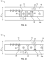
- FIGs. 3a - 3d Other exemplary configurations of fins 26 are illustrated in FIGs. 3a - 3d .
- the fin 26 extends from a first heat exchanger plate 14a to a second heat exchange plate 14b, and the fin thickness 30 varies with distance from the heat exchanger plates 14a, 14b.
- the fin 26 decreases in fin thickness 30 as distance from the heat exchanger plates 14a, 14b increases, resulting the fin 26 having, in the embodiment shown, a double triangular, or "bow-tie" shaped cross-section.
- FIG. 3a the fin 26 decreases in fin thickness 30 as distance from the heat exchanger plates 14a, 14b increases, resulting the fin 26 having, in the embodiment shown, a double triangular, or "bow-tie" shaped cross-section.
- the fin 26 extends only partially between the first heat exchanger plate 14a and the second heat exchanger plate 14b, from a fin base 34 to a fin tip 36.
- the fin thickness 30 may be constant along the fin height 32, while in other embodiments as shown in FIG. 3b , the fin thickness 30 may vary or taper from the fin base 34 to the fin tip 36.
- the fins 26 may have internal porous areas 38, which improve heat transfer properties of the fins 26, while reducing weight.
- the fin 26 having internal porous areas 38 has a uniform external cross-section, for example, a rectangular cross-section.
- the fins 26 may have other external cross-sectional shapes, such that the overall fin thickness 30 is varied.
- the internal porous areas 38 may be uniform and constant, or alternatively may vary depending on the location of the porous area 38 in the fin 26. It is to be appreciated that the fin 26 structures illustrated in FIGs. 3a-3d and described herein are merely exemplary and one skilled in the art will readily appreciate that other fin 36 configurations may be utilized to provide the desired heat transfer performance of the heat exchanger 10.
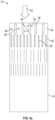
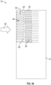
- Forming the fins 26 via one or more additive manufacturing processes enables a variety of arrangements and distributions of fins 26 as illustrated in FIG. 4a and 4b .
- the fins 26 are arranged in a plurality of fin rows 40, with each fin row 40 extending across a flow direction 42 and the fin rows 40 arrayed along the flow direction 42.
- fins 26 of a particular fin row 40 have the same fin thickness 30 and/or fin spacing 44, while the fin thickness 30 and/or fin spacing 44 may vary by fin row 40.
- a first fin row 40 may have a first fin spacing 44 and fins having a first fin thickness 30, while a second fin row 40 may have a second fin spacing 44 different from the first fin spacing 44, and fins having a second fin thickness 30 different from the first fin thickness 30.
- turbulators 46 may be positioned between adjacent fins 26 in selected fin rows 40.
- the fins 26 are in some embodiments formed with perforations formed therein to define secondary flow passages 48 through an interior 50 of the fins 26. This configuration further increases the heat transfer performance of the fins 26 and of the heat exchanger 10 overall.
Landscapes
- Engineering & Computer Science (AREA)
- Physics & Mathematics (AREA)
- Thermal Sciences (AREA)
- Mechanical Engineering (AREA)
- General Engineering & Computer Science (AREA)
- Chemical & Material Sciences (AREA)
- Manufacturing & Machinery (AREA)
- Materials Engineering (AREA)
- Heat-Exchange Devices With Radiators And Conduit Assemblies (AREA)
Abstract
A heat exchanger includes a plurality of heat exchanger plates (14a, 14b) stacked along a stacking axis defining a plurality of first pathways (18) through which a first fluid is directed, and a plurality of fins (26) located between adjacent first pathways of the plurality of first pathways. The plurality of fins at least partially define a plurality of second pathways (22) through which a second fluid is directed. The heat exchanger plates are formed from a sheet material, and the plurality of fins are formed from one or more additive manufacturing processes.
Description
- Exemplary embodiments pertain to the art of heat exchangers and in particular to the construction of heat exchanger fin disposed between opposing heat exchanger plates.
- Heat exchangers are utilized in a variety of applications, such as cooling of engines or motors, climate control (heating, ventilation and air conditioning systems) or the like. Utilizing additive manufacturing techniques, such as 3D printing or the like, in manufacturing heat exchangers allows for the manufacture of shapes and configurations of heat exchangers not easily achieved via conventional manufacturing operations.
- Utilizing additive manufacturing processes, however, imposes certain geometrical constraints on the heat exchanger configuration. For instance, due to 3D printing constraints, the geometry is limited in maximum horizontal angle to about 45 degrees. This results in longer transition from a header to the high surface area sections of a heat exchanger body, thus lowering overall effectiveness of the heat exchanger (HX), or alternatively requiring additional supports to be incorporated to the structure during manufacture. The additional supports may be difficult to access and remove in the locations inside of the unit once manufacture of the heat exchanger is completed.
- In one aspect, a heat exchanger includes a plurality of heat exchanger plates stacked along a stacking axis defining a plurality of first pathways through which a first fluid is directed, and a plurality of fins located between adjacent first pathways of the plurality of first pathways. The plurality of fins at least partially define a plurality of second pathways through which a second fluid is directed. The heat exchanger plates are formed from a sheet material, and the plurality of fins are formed from one or more additive manufacturing processes.
- In embodiments a plurality of plate openings are located in the plurality of heat exchanger plates, and a fin of the plurality of fins is formed extending into each of the plurality of plate openings to secure the plurality of fins to the heat exchanger plate.
- In embodiments a fin thickness of the plurality of fins varies along a fin height direction.
- In embodiments a fin of the plurality of fins is formed with one or more porous areas internal to the fin.
- In embodiments the fin includes one or more perforations extending into the porous area to define a secondary pathway through the fin.
- In embodiments the plurality of fins are arranged in a plurality of rows. Each row extends across a flow direction of the second fluid through the plurality of second pathways.
- In embodiments one or more of a fin spacing and a fin thickness is varied between a first row of the plurality of rows and a second row of the plurality of rows.
- In embodiments a turbulator is positioned between adjacent fins of the plurality of fins.
- In embodiments the heat exchanger plates are formed from a sheet metal material.
- In embodiments the plurality of heat exchanger plates define a plurality of heat exchanger layers along the stacking axis, and a first heat exchanger layer of the plurality of heat exchanger layers includes the plurality of fins formed from one or more additive manufacturing processes. A second heat exchanger layer of the plurality of heat exchanger layers includes a plurality of fins formed not from one or more additive manufacturing processes.
- In embodiments the heat exchanger is one of a cross-flow heat exchanger, a counterflow heat exchanger or a parallel flow heat exchanger.
- In another aspect, a method of forming a heat exchanger includes stacking a plurality of heat exchanger plates along a stacking axis thereby defining a plurality of first fluid pathways through which a first fluid is directed and positioning a plurality of fins between adjacent first fluid pathways to at least partially define a plurality of second fluid pathways through which a second fluid is directed. The heat exchanger plates are formed from a sheet material, and the plurality of fins are formed from one or more additive manufacturing processes.
- In embodiments a plurality of plate openings are formed in the plurality of heat exchanger plates, and a fin of the plurality of fins is formed to extend into each of the plurality of plate openings to secure the plurality of fins to the heat exchanger plate.
- In embodiments a fin thickness of the plurality of fins is varied along a fin height direction.
- In embodiments a fin of the plurality of fins is formed with one or more porous areas internal to the fin.
- In embodiments the fin includes one or more perforations extending into the porous area to define a secondary pathway through the fin.
- In embodiments the plurality of fins are arranged in a plurality of rows. Each row extends across a flow direction of the second fluid through the plurality of second pathways.
- In embodiments one or more of a fin spacing and a fin thickness is varied between a first row of the plurality of rows and a second row of the plurality of rows.
- In embodiments the heat exchanger plates are formed from a sheet metal material.
- In embodiments the one or more additive manufacturing processes includes 3D printing.
- The following descriptions should not be considered limiting in any way. With reference to the accompanying drawings, like elements are numbered alike:
-
FIG. 1 is a partial cross-sectional illustration of an embodiment of a heat exchanger; -
FIG. 2 is a schematic illustration of an exemplary embodiment of a fin structure of a heat exchanger; -
FIG. 3a is a schematic illustration of another exemplary embodiment of a fin structure of a heat exchanger; -
FIG. 3b is a schematic illustration of yet another exemplary embodiment of a fin structure of a heat exchanger; -
FIG. 3c is a schematic illustration of still another exemplary embodiment of a fin structure of a heat exchanger; -
FIG. 3d is a schematic illustration of another exemplary embodiment of a fin structure of a heat exchanger; -
FIG. 4a is a schematic illustration of an exemplary fin arrangement of a heat exchanger; -
FIG. 4b is a schematic illustration of another exemplary fin arrangement of a heat exchanger; and -
FIG. 5 is a schematic illustration of still another exemplary embodiment of a fin structure of a heat exchanger. - A detailed description of one or more embodiments of the disclosed apparatus and method are presented herein by way of exemplification and not limitation with reference to the Figures.
- Referring now to
FIG. 1 , illustrated is a partial cross-section view of an embodiment of aheat exchanger 10. Theheat exchanger 10 includes aheat exchanger body 12 having a plurality of heat exchanger plates 14 (shown as 14a and 14b) spaced apart and stacked along astacking axis 16 defining a plurality of heat exchanger layers along thestacking axis 16. The stack ofheat exchanger plates 14 defines one or morefirst pathways 18 through which afirst fluid 20 is directed. In some embodiments thefirst fluid 20 is a relatively hot gas.Second pathways 22 are located between adjacentfirst pathways 18 along thestacking axis 16. Asecond fluid 24 is directed through thesecond pathways 22, and in some embodiments may be a relatively cold gas. In the embodiment ofFIG. 1 , thefirst fluid 20 is directed in a first direction and thesecond fluid 24 is directed in a second direction substantially perpendicular to the first direction so that theheat exchanger 10 is a crossflow heat exchanger. It is to be appreciated that this configuration is merely exemplary and that the present disclosure may be utilized inother heat exchanger 10, such ascounterflow heat exchangers 10 where the second direction is opposite the first direction, or parallel-flow heat exchangers where the first direction is the same as the second direction. - To enhance performance of the
heat exchanger 10,fins 26 or other features extend at least partially across thesecond pathways 22. While thefins 26 are illustrated herein to be in thesecond pathways 22, one skilled in the art will appreciate thatfins 26 may alternatively or additionally be located in thefirst pathways 18. Thefins 26 act to increase turbulence in the fluid flow and also to increase an effective heat exchange surface, thereby improving a heat transfer rate of theheat exchanger 10. - The
heat exchanger plates 14 are, for example, sheet metal plates or plates formed from other materials having the desired heat transfer properties forheat exchanger 10 performance. Thefins 26 are formed by one or more additive manufacturing processes, such as 3D printing. In some embodiments, thefins 26 are formed by additive manufacturing in place on theheat exchanger plates 14 prior to stacking of theheat exchanger plates 14. Theheat exchanger plates 14 may includeplate openings 28 or perforations therein, with thefins 26 partially extending into theplate openings 28 to adhere thefins 26 to theheat exchanger plates 14. While in some embodiments, all of thefins 26 are formed from additive manufacturing processes, in some embodiments theheat exchanger 10 may include a combination of additively-manufacture fins and traditionally manufactured fins. While in some embodiments, theheat exchanger plates 14 includeplate openings 28, in other embodiments theheat exchanger plates 14 are continuous and do not includeplate openings 28. For example, additively-manufacturedfins 26 and traditionally manufactured fins may be utilized in alternating layers of theheat exchanger 10. - Such hybrid construction of the
heat exchanger 10 allows for different and varying configurations offins 26 in the layers of theheat exchanger 10. In one embodiment, inFIG. 2 , thefins 26 may be simply rectangular in cross-section with aconstant fin thickness 30 along afin height 32 extending between the adjacentheat exchanger plates 14. - Other exemplary configurations of
fins 26 are illustrated inFIGs. 3a - 3d . In the embodiment ofFIG. 3a , thefin 26 extends from a firstheat exchanger plate 14a to a secondheat exchange plate 14b, and thefin thickness 30 varies with distance from theheat exchanger plates FIG. 3a , thefin 26 decreases infin thickness 30 as distance from theheat exchanger plates fin 26 having, in the embodiment shown, a double triangular, or "bow-tie" shaped cross-section. In other embodiments, such as shown inFIG. 3b , thefin 26 extends only partially between the firstheat exchanger plate 14a and the secondheat exchanger plate 14b, from afin base 34 to afin tip 36. In such configurations, thefin thickness 30 may be constant along thefin height 32, while in other embodiments as shown inFIG. 3b , thefin thickness 30 may vary or taper from thefin base 34 to thefin tip 36. In other embodiments such as shown inFIG. 3c and 3d , thefins 26 may have internalporous areas 38, which improve heat transfer properties of thefins 26, while reducing weight. In the embodiment ofFIG. 3c , thefin 26 having internalporous areas 38 has a uniform external cross-section, for example, a rectangular cross-section. In other embodiments, however, thefins 26 may have other external cross-sectional shapes, such that theoverall fin thickness 30 is varied. The internalporous areas 38 may be uniform and constant, or alternatively may vary depending on the location of theporous area 38 in thefin 26. It is to be appreciated that thefin 26 structures illustrated inFIGs. 3a-3d and described herein are merely exemplary and one skilled in the art will readily appreciate thatother fin 36 configurations may be utilized to provide the desired heat transfer performance of theheat exchanger 10. - Forming the
fins 26 via one or more additive manufacturing processes enables a variety of arrangements and distributions offins 26 as illustrated inFIG. 4a and4b . In each of the illustrated embodiments, thefins 26 are arranged in a plurality offin rows 40, with eachfin row 40 extending across aflow direction 42 and thefin rows 40 arrayed along theflow direction 42. In some embodiments,fins 26 of aparticular fin row 40 have thesame fin thickness 30 and/orfin spacing 44, while thefin thickness 30 and/orfin spacing 44 may vary byfin row 40. For example, afirst fin row 40 may have afirst fin spacing 44 and fins having afirst fin thickness 30, while asecond fin row 40 may have a second fin spacing 44 different from the first fin spacing 44, and fins having asecond fin thickness 30 different from thefirst fin thickness 30. Additionally, in some embodiments, turbulators 46 may be positioned betweenadjacent fins 26 in selectedfin rows 40. - Referring now to
FIG. 5 , thefins 26 are in some embodiments formed with perforations formed therein to definesecondary flow passages 48 through an interior 50 of thefins 26. This configuration further increases the heat transfer performance of thefins 26 and of theheat exchanger 10 overall. - Such hybrid construction of the
heat exchanger 10, withheat exchanger plates 14 andfins 26 formed from one or more additive manufacturing processes extending between adjacentheat exchanger plates 14, improves thermal performance of theheat exchanger 10 while enabling a reduction in weight. Further, use of conventionalheat exchanger plates 14 reduces pressure losses on theheat exchanger plates 14 due to low surface roughness of theheat exchanger plates 14. Further, the hybrid construction enables incorporation of advantageous aspects of both plate and additive manufacturing heat exchanger configurations while controlling cost of theheat exchanger 10. - The term "about" is intended to include the degree of error associated with measurement of the particular quantity based upon the equipment available at the time of filing the application.
- The terminology used herein is for the purpose of describing particular embodiments only and is not intended to be limiting of the present disclosure. As used herein, the singular forms "a", "an" and "the" are intended to include the plural forms as well, unless the context clearly indicates otherwise. It will be further understood that the terms "comprises" and/or "comprising," when used in this specification, specify the presence of stated features, integers, steps, operations, elements, and/or components, but do not preclude the presence or addition of one or more other features, integers, steps, operations, element components, and/or groups thereof.
- While the present disclosure has been described with reference to an exemplary embodiment or embodiments, it will be understood by those skilled in the art that various changes may be made without departing from the scope of the invention as defined by the claims. In addition, many modifications may be made to adapt a particular situation or material to the teachings of the present disclosure without departing from the scope of the claims.
Claims (15)
- A heat exchanger, comprising:a plurality of heat exchanger plates (14a, 14b) stacked along a stacking axis defining a plurality of first pathways (18) through which a first fluid is directed; anda plurality of fins (26) disposed between adjacent first pathways of the plurality of first pathways, the plurality of fins at least partially defining a plurality of second pathways (22) through which a second fluid is directed;wherein the heat exchanger plates are formed from a sheet material; andwherein the plurality of fins are formed from one or more additive manufacturing processes.
- The heat exchanger of claim 1, further comprising a plurality of plate openings (28) in the plurality of heat exchanger plates;
wherein a fin of the plurality of fins is formed extending into each of the plurality of plate openings to secure the plurality of fins to the heat exchanger plate. - The heat exchanger of claim 1 or 2, wherein a fin thickness of the plurality of fins varies along a fin height direction.
- The heat exchanger of any preceding claim, wherein a fin of the plurality of fins is formed with one or more porous areas internal to the fin, and optionally wherein the fin includes one or more perforations extending into the porous area to define a secondary pathway through the fin.
- The heat exchanger of any preceding claim, wherein the plurality of fins are arranged in a plurality of rows, each row extending across a flow direction of the second fluid through the plurality of second pathways.
- The heat exchanger of claim 5, wherein one or more of a fin spacing and a fin thickness is varied between a first row of the plurality of rows and a second row of the plurality of rows.
- The heat exchanger of any preceding claim, further comprising a turbulator (46) disposed between adjacent fins of the plurality of fins.
- The heat exchanger of any preceding claim, wherein the heat exchanger plates are formed from a sheet metal material.
- The heat exchanger of any preceding claim, wherein:the plurality of heat exchanger plates define a plurality of heat exchanger layers along the stacking axis; andwherein a first heat exchanger layer of the plurality of heat exchanger layers includes the plurality of fins formed from one or more additive manufacturing processes; andwherein a second heat exchanger layer of the plurality of heat exchanger layers includes a plurality of fins formed not from one or more additive manufacturing processes.
- A method of forming a heat exchanger, comprising:stacking a plurality of heat exchanger plates (14a, 14b) along a stacking axis thereby defining a plurality of first fluid pathways (18) through which a first fluid is directed;positioning a plurality of fins (26) between adjacent first fluid pathways to at least partially define a plurality of second fluid pathways (22) through which a second fluid is directed;wherein the heat exchanger plates are formed from a sheet material; andwherein the plurality of fins are formed from one or more additive manufacturing processes.
- The method of claim 10, further comprising forming a plurality of plate openings (28) in the plurality of heat exchanger plates; and
forming a fin of the plurality of fins to extend into each of the plurality of plate openings to secure the plurality of fins to the heat exchanger plate. - The method of claim 10 or 11, further comprising varying a fin thickness of the plurality of fins along a fin height direction.
- The method of claim 10, 11 or 12, further comprising forming a fin of the plurality of fins with one or more porous areas internal to the fin, and optionally further comprising forming the fin including one or more perforations extending into the porous area to define a secondary pathway through the fin.
- The method of any of claims 10 to 13, further comprising arranging the plurality of fins in a plurality of rows, each row extending across a flow direction of the second fluid through the plurality of second pathways, and optionally further comprising varying one or more of a fin spacing and a fin thickness between a first row of the plurality of rows and a second row of the plurality of rows.
- The method of any of claims 10 to 14, wherein the one or more additive manufacturing processes includes 3D printing.
Applications Claiming Priority (1)
| Application Number | Priority Date | Filing Date | Title |
|---|---|---|---|
| US18/491,913 US20250129996A1 (en) | 2023-10-23 | 2023-10-23 | Heat exchanger with internal cross flow fins |
Publications (1)
| Publication Number | Publication Date |
|---|---|
| EP4545303A1 true EP4545303A1 (en) | 2025-04-30 |
Family
ID=93213842
Family Applications (1)
| Application Number | Title | Priority Date | Filing Date |
|---|---|---|---|
| EP24207755.0A Pending EP4545303A1 (en) | 2023-10-23 | 2024-10-21 | HEAT EXCHANGER WITH INTERNAL CROSS-FLOW FINS |
Country Status (2)
| Country | Link |
|---|---|
| US (1) | US20250129996A1 (en) |
| EP (1) | EP4545303A1 (en) |
Citations (5)
| Publication number | Priority date | Publication date | Assignee | Title |
|---|---|---|---|---|
| US20150137412A1 (en) * | 2013-11-20 | 2015-05-21 | Carl Schalansky | Method of using additive materials for production of fluid flow channels |
| US20180015539A1 (en) * | 2016-07-12 | 2018-01-18 | Hamilton Sundstrand Corporation | Additive manufacturing method |
| US20190301816A1 (en) * | 2018-03-27 | 2019-10-03 | Hamilton Sundstrand Corporation | Additively manufactured heat exchangers and methods for making the same |
| US10845132B2 (en) * | 2018-11-05 | 2020-11-24 | Hamilton Sundstrand Corporation | Additively manufactured fin slots for thermal growth |
| US11686537B2 (en) * | 2021-04-06 | 2023-06-27 | General Electric Company | Heat exchangers and methods of manufacturing the same |
Family Cites Families (9)
| Publication number | Priority date | Publication date | Assignee | Title |
|---|---|---|---|---|
| US20150361922A1 (en) * | 2014-06-13 | 2015-12-17 | Honeywell International Inc. | Heat exchanger designs using variable geometries and configurations |
| US10907500B2 (en) * | 2015-02-06 | 2021-02-02 | Raytheon Technologies Corporation | Heat exchanger system with spatially varied additively manufactured heat transfer surfaces |
| US20170023311A1 (en) * | 2015-07-24 | 2017-01-26 | Nicholas F. Urbanski | Enhanced Heat Transfer In Plate-Fin Heat Exchangers |
| US11346608B2 (en) * | 2016-01-29 | 2022-05-31 | Deere & Company | Heat exchanger with improved plugging resistance |
| US20170356696A1 (en) * | 2016-06-13 | 2017-12-14 | Hamilton Sundstrand Corporation | Complex pin fin heat exchanger |
| FR3058510B1 (en) * | 2016-11-10 | 2019-08-16 | Safran | HEAT EXCHANGER |
| DE202017103830U1 (en) * | 2017-06-27 | 2018-10-01 | Autokühler GmbH & Co KG | heat exchangers |
| US20200080796A1 (en) * | 2018-09-11 | 2020-03-12 | Siemens Aktiengesellschaft | Additive manufactured heat exchanger |
| EP4498030A1 (en) * | 2023-07-25 | 2025-01-29 | HS Marston Aerospace Limited | Heat exchanger |
-
2023
- 2023-10-23 US US18/491,913 patent/US20250129996A1/en active Pending
-
2024
- 2024-10-21 EP EP24207755.0A patent/EP4545303A1/en active Pending
Patent Citations (5)
| Publication number | Priority date | Publication date | Assignee | Title |
|---|---|---|---|---|
| US20150137412A1 (en) * | 2013-11-20 | 2015-05-21 | Carl Schalansky | Method of using additive materials for production of fluid flow channels |
| US20180015539A1 (en) * | 2016-07-12 | 2018-01-18 | Hamilton Sundstrand Corporation | Additive manufacturing method |
| US20190301816A1 (en) * | 2018-03-27 | 2019-10-03 | Hamilton Sundstrand Corporation | Additively manufactured heat exchangers and methods for making the same |
| US10845132B2 (en) * | 2018-11-05 | 2020-11-24 | Hamilton Sundstrand Corporation | Additively manufactured fin slots for thermal growth |
| US11686537B2 (en) * | 2021-04-06 | 2023-06-27 | General Electric Company | Heat exchangers and methods of manufacturing the same |
Also Published As
| Publication number | Publication date |
|---|---|
| US20250129996A1 (en) | 2025-04-24 |
Similar Documents
| Publication | Publication Date | Title |
|---|---|---|
| EP2015018B1 (en) | Heat transfer fin and fin-tube heat exchanger | |
| US5078207A (en) | Heat exchanger and fin for the same | |
| US20050045314A1 (en) | Aluminum heat exchanger and method of making thereof | |
| CN113720174B (en) | Microchannel heat exchanger | |
| KR20130036762A (en) | Serpentine heat exchanger for an air conditioner | |
| WO2013069358A1 (en) | Serpentine heat exchanger for air conditioner | |
| CN104937362B (en) | heat exchanger | |
| US12624904B2 (en) | Heat exchanger and refrigeration cycle apparatus | |
| US4854380A (en) | Heat exchanger | |
| JP2014020580A (en) | Fin tube type heat exchanger | |
| WO2006028253A1 (en) | Heat exchanger | |
| EP3176533A1 (en) | Cross flow ceramic heat exchanger and method for manufacturing | |
| JP2001041678A (en) | Heat exchanger | |
| US20250129996A1 (en) | Heat exchanger with internal cross flow fins | |
| KR20060012303A (en) | Fins for heat exchangers, heat exchangers, condensers, and evaporators | |
| EP0838650B1 (en) | Humped plate fin heat exchangers | |
| US10502501B1 (en) | Louvered elliptical tube micro-lattice heat exchangers | |
| US12078431B2 (en) | Microchannel heat exchanger for a furnace | |
| US7299863B2 (en) | Louver fin type heat exchanger having improved heat exchange efficiency by controlling water blockage | |
| US20120312515A1 (en) | Apparatus for heat dissipation of transforming radiators | |
| CN113266879B (en) | Air conditioner | |
| CN103717993B (en) | Finned Tube Heat Exchanger | |
| US11187470B2 (en) | Plate fin crossflow heat exchanger | |
| JP2011185589A (en) | Serpentine heat exchanger for air conditioner | |
| KR20030020563A (en) | Louver fin for heat exchanger |
Legal Events
| Date | Code | Title | Description |
|---|---|---|---|
| PUAI | Public reference made under article 153(3) epc to a published international application that has entered the european phase |
Free format text: ORIGINAL CODE: 0009012 |
|
| STAA | Information on the status of an ep patent application or granted ep patent |
Free format text: STATUS: THE APPLICATION HAS BEEN PUBLISHED |
|
| AK | Designated contracting states |
Kind code of ref document: A1 Designated state(s): AL AT BE BG CH CY CZ DE DK EE ES FI FR GB GR HR HU IE IS IT LI LT LU LV MC ME MK MT NL NO PL PT RO RS SE SI SK SM TR |
|
| STAA | Information on the status of an ep patent application or granted ep patent |
Free format text: STATUS: REQUEST FOR EXAMINATION WAS MADE |
|
| 17P | Request for examination filed |
Effective date: 20251030 |