EP4545301A1 - Heat exchanger and header construction - Google Patents
Heat exchanger and header construction Download PDFInfo
- Publication number
- EP4545301A1 EP4545301A1 EP24203737.2A EP24203737A EP4545301A1 EP 4545301 A1 EP4545301 A1 EP 4545301A1 EP 24203737 A EP24203737 A EP 24203737A EP 4545301 A1 EP4545301 A1 EP 4545301A1
- Authority
- EP
- European Patent Office
- Prior art keywords
- heat exchanger
- outlet
- inlet
- manifold
- fluid
- Prior art date
- Legal status (The legal status is an assumption and is not a legal conclusion. Google has not performed a legal analysis and makes no representation as to the accuracy of the status listed.)
- Pending
Links
Images



Classifications
-
- F—MECHANICAL ENGINEERING; LIGHTING; HEATING; WEAPONS; BLASTING
- F28—HEAT EXCHANGE IN GENERAL
- F28D—HEAT-EXCHANGE APPARATUS, NOT PROVIDED FOR IN ANOTHER SUBCLASS, IN WHICH THE HEAT-EXCHANGE MEDIA DO NOT COME INTO DIRECT CONTACT
- F28D1/00—Heat-exchange apparatus having stationary conduit assemblies for one heat-exchange medium only, the media being in contact with different sides of the conduit wall, in which the other heat-exchange medium is a large body of fluid, e.g. domestic or motor car radiators
- F28D1/02—Heat-exchange apparatus having stationary conduit assemblies for one heat-exchange medium only, the media being in contact with different sides of the conduit wall, in which the other heat-exchange medium is a large body of fluid, e.g. domestic or motor car radiators with heat-exchange conduits immersed in the body of fluid
- F28D1/04—Heat-exchange apparatus having stationary conduit assemblies for one heat-exchange medium only, the media being in contact with different sides of the conduit wall, in which the other heat-exchange medium is a large body of fluid, e.g. domestic or motor car radiators with heat-exchange conduits immersed in the body of fluid with tubular conduits
- F28D1/053—Heat-exchange apparatus having stationary conduit assemblies for one heat-exchange medium only, the media being in contact with different sides of the conduit wall, in which the other heat-exchange medium is a large body of fluid, e.g. domestic or motor car radiators with heat-exchange conduits immersed in the body of fluid with tubular conduits the conduits being straight
- F28D1/05316—Assemblies of conduits connected to common headers, e.g. core type radiators
- F28D1/05333—Assemblies of conduits connected to common headers, e.g. core type radiators with multiple rows of conduits or with multi-channel conduits
-
- B—PERFORMING OPERATIONS; TRANSPORTING
- B23—MACHINE TOOLS; METAL-WORKING NOT OTHERWISE PROVIDED FOR
- B23P—METAL-WORKING NOT OTHERWISE PROVIDED FOR; COMBINED OPERATIONS; UNIVERSAL MACHINE TOOLS
- B23P15/00—Making specific metal objects by operations not covered by a single other subclass or a group in this subclass
- B23P15/26—Making specific metal objects by operations not covered by a single other subclass or a group in this subclass heat exchangers or the like
-
- B—PERFORMING OPERATIONS; TRANSPORTING
- B33—ADDITIVE MANUFACTURING TECHNOLOGY
- B33Y—ADDITIVE MANUFACTURING, i.e. MANUFACTURING OF THREE-DIMENSIONAL [3D] OBJECTS BY ADDITIVE DEPOSITION, ADDITIVE AGGLOMERATION OR ADDITIVE LAYERING, e.g. BY 3D PRINTING, STEREOLITHOGRAPHY OR SELECTIVE LASER SINTERING
- B33Y80/00—Products made by additive manufacturing
-
- F—MECHANICAL ENGINEERING; LIGHTING; HEATING; WEAPONS; BLASTING
- F28—HEAT EXCHANGE IN GENERAL
- F28F—DETAILS OF HEAT-EXCHANGE AND HEAT-TRANSFER APPARATUS, OF GENERAL APPLICATION
- F28F7/00—Elements not covered by group F28F1/00, F28F3/00 or F28F5/00
- F28F7/02—Blocks traversed by passages for heat-exchange media
-
- F—MECHANICAL ENGINEERING; LIGHTING; HEATING; WEAPONS; BLASTING
- F28—HEAT EXCHANGE IN GENERAL
- F28F—DETAILS OF HEAT-EXCHANGE AND HEAT-TRANSFER APPARATUS, OF GENERAL APPLICATION
- F28F9/00—Casings; Header boxes; Auxiliary supports for elements; Auxiliary members within casings
- F28F9/02—Header boxes; End plates
- F28F9/026—Header boxes; End plates with static flow control means, e.g. with means for uniformly distributing heat exchange media into conduits
- F28F9/027—Header boxes; End plates with static flow control means, e.g. with means for uniformly distributing heat exchange media into conduits in the form of distribution pipes
- F28F9/0275—Header boxes; End plates with static flow control means, e.g. with means for uniformly distributing heat exchange media into conduits in the form of distribution pipes with multiple branch pipes
-
- F—MECHANICAL ENGINEERING; LIGHTING; HEATING; WEAPONS; BLASTING
- F28—HEAT EXCHANGE IN GENERAL
- F28D—HEAT-EXCHANGE APPARATUS, NOT PROVIDED FOR IN ANOTHER SUBCLASS, IN WHICH THE HEAT-EXCHANGE MEDIA DO NOT COME INTO DIRECT CONTACT
- F28D7/00—Heat-exchange apparatus having stationary tubular conduit assemblies for both heat-exchange media, the media being in contact with different sides of a conduit wall
- F28D7/16—Heat-exchange apparatus having stationary tubular conduit assemblies for both heat-exchange media, the media being in contact with different sides of a conduit wall the conduits being arranged in parallel spaced relation
-
- F—MECHANICAL ENGINEERING; LIGHTING; HEATING; WEAPONS; BLASTING
- F28—HEAT EXCHANGE IN GENERAL
- F28F—DETAILS OF HEAT-EXCHANGE AND HEAT-TRANSFER APPARATUS, OF GENERAL APPLICATION
- F28F9/00—Casings; Header boxes; Auxiliary supports for elements; Auxiliary members within casings
- F28F9/02—Header boxes; End plates
- F28F2009/0285—Other particular headers or end plates
- F28F2009/0297—Side headers, e.g. for radiators having conduits laterally connected to common header
-
- F—MECHANICAL ENGINEERING; LIGHTING; HEATING; WEAPONS; BLASTING
- F28—HEAT EXCHANGE IN GENERAL
- F28F—DETAILS OF HEAT-EXCHANGE AND HEAT-TRANSFER APPARATUS, OF GENERAL APPLICATION
- F28F2210/00—Heat exchange conduits
- F28F2210/02—Heat exchange conduits with particular branching, e.g. fractal conduit arrangements
Definitions
- Exemplary embodiments pertain to the art of heat exchangers and in particular to the construction of fluid-air heat exchangers having fluid headers.
- Heat exchangers are utilized in a variety of applications, such as cooling of engines or motors, climate control (heating, ventilation and air conditioning systems) or the like. Utilizing additive manufacturing techniques, such as 3D printing or the like, in manufacturing heat exchangers allows for the manufacture of shapes and configurations of heat exchangers not easily achieved via conventional manufacturing operations.
- a heat exchanger in one exemplary embodiment, includes a heat exchanger body having a plurality of heat exchanger tubes, an inlet manifold connected to the heat exchanger body and configured to distribute a flow of fluid from a fluid inlet of the inlet manifold to the plurality of heat exchanger tubes, and an outlet manifold connected to the heat exchanger body and configured to collect the flow of fluid from the plurality of heat exchanger tubes and direct the flow of fluid through a fluid outlet.
- the heat exchanger body is formed via one or more additive manufacturing processes, and at least one of the inlet manifold and the outlet manifold is formed via one or more subtractive manufacturing processes.
- the heat exchanger body includes a plurality of fins connecting heat exchanger tubes of the plurality of heat exchanger tubes.
- the inlet manifold includes a plurality of inlet passages connecting the fluid inlet to the plurality of heat exchanger tubes.
- the plurality of inlet passages includes a plurality of first inlet passages extending from the fluid inlet and a plurality of second inlet passages branching off from the plurality of first inlet passages.
- the outlet manifold includes a plurality of outlet passages connecting the fluid outlet to the plurality of heat exchanger tubes.
- the plurality of outlet passages includes a plurality of first outlet passages extending from the plurality of heat exchanger tubes and a plurality of second outlet passages.
- Each second outlet passage of the plurality of second outlet passages is fluidly connected to two or more first outlet passages of the plurality of first outlet passages.
- the additive manufacturing processes includes 3D printing.
- the subtractive manufacturing processes includes one or more of machining and milling.
- a method of forming a heat exchanger includes forming a heat exchanger body including a plurality of heat exchanger tubes via one or more additive manufacturing processes, and forming at least one of the inlet manifold and the outlet manifold via one or more subtractive manufacturing processes.
- the inlet manifold is connected to the heat exchanger body and is configured to distribute a flow of fluid from a fluid inlet of the inlet manifold to the plurality of heat exchanger tubes.
- the outlet manifold is connected to the heat exchanger body and is configured to collect the flow of fluid from the plurality of heat exchanger tubes and direct the flow of fluid through a fluid outlet.
- one of the inlet manifold and the outlet manifold is utilized as a base for forming the heat exchanger body via the one or more additive manufacturing processes.
- a block is formed at the location of one of the inlet manifold and the outlet manifold via one or more additive manufacturing processes simultaneously with the forming of the heat exchanger body.
- One of the inlet manifold and the outlet manifold are formed from the block via one or more subtractive manufacturing processes.
- a block is formed at the locations of both of the inlet manifold and the outlet manifold via one or more additive manufacturing processes simultaneously with the forming of the heat exchanger body. Both of the inlet manifold and the outlet manifold are formed from the blocks via one or more subtractive manufacturing processes.
- both of the inlet manifold and the outlet manifold are formed separately from the heat exchanger body, and the inlet manifold and the outlet manifold are secured to the heat exchanger body after forming of the heating exchanger body.
- the heat exchanger body includes a plurality of fins connecting heat exchanger tubes of the plurality of heat exchanger tubes.
- the inlet manifold includes a plurality of inlet passages connecting the fluid inlet to the plurality of heat exchanger tubes.
- the plurality of inlet passages includes a plurality of first inlet passages extending from the fluid inlet and a plurality of second inlet passages branching off from the plurality of first inlet passages.
- the outlet manifold includes a plurality of outlet passages connecting the fluid outlet to the plurality of heat exchanger tubes.
- the plurality of outlet passages includes a plurality of first outlet passages extending from the plurality of heat exchanger tubes and a plurality of second outlet passages.
- Each second outlet passage of the plurality of second outlet passages is fluidly connected to two or more first outlet passages of the plurality of first outlet passages.
- the additive manufacturing processes includes 3D printing.
- the subtractive manufacturing processes includes one or more of machining and milling.
- the heat exchanger 10 includes a heat exchanger body 12 having a plurality of body tubes 14 extending from a first body end 16 to a second body end 18, opposite the first body end 16.
- the body tubes 14 extend linearly from the first body end 16 to the second body end 18, while in other embodiments, such as shown in FIG. 1 , the body tubes 14 extend curvilinearly from the first body end 16 to the second body end 18.
- the body tubes 14 extend a combination of linearly and curvilinearly along their length from the first body end 16 to the second body end 18.
- the body tubes 14 may have a constant size and shape along their length, or alternatively one or more of the tube size and tube shape may vary along their length.
- the heat exchanger body 12 includes a plurality of fins 20.
- the fins 20 may extend between adjacent body tubes 14 and along a length of the body tubes 14 to interconnect the body tubes 14 and increase surface area of the heat exchanger body 12 and improve effectiveness of the heat exchanger 10.
- the body tubes 14 are configured to direct a flow of fluid 22 through the heat exchanger body 12.
- a flow of air 24 is directed across the body tubes 14 by, for example, a fan 26, and the flow of fluid 22 is cooled, or alternatively heated, via exchange of thermal energy between the flow of air 24 and the flow of fluid 22 via the heat exchanger body 12.
- the inlet manifold 30 includes an inlet manifold body 32 at which the fluid inlet 28 is located, and a plurality of first inlet passages 34 branching from the inlet manifold body 32.
- a plurality of second inlet passages 36 branch from each of the first inlet passages 34, and a plurality of third inlet passages 38 branch from each of the second inlet passages 36.
- the plurality of third inlet passages 38 are each connected to a body tube 14 of the plurality of body tubes 14 to direct the flow of fluid 22 into the body tubes 14.
- the inlet passages 34, 36, 38 are configured and sized to distribute selected proportions of the flow of fluid 22 into each of the body tubes 14, in some embodiments the selected proportions are equal amounts of the flow of fluid 22 into each of the body tubes 14.
- the inlet manifold 30 described herein distributes the flow of fluid 22 to the body tubes 14 via the inlet passages 34, 36, 38
- this configuration is merely exemplary and that other configurations of passages or features may be utilized at the inlet manifold 30 to distribute the flow of fluid 14 into the body tubes 14.
- the outlet manifold 40 includes a plurality of first outlet passages 44, each first outlet passage 44 connected to a body tube 14 of the heat exchanger body 12 to collect the flow of fluid 22 from the body tubes 14.
- a plurality of second outlet passages 46 collect the flow of fluid 22 from the first outlet passages 44, where each second outlet passage 46 is connected to a number of first outlet passages 44.
- a plurality of third outlet passages 48 collect the flow of fluid 22 from the second outlet passages 46, where each third outlet passage 48 is connected to a number of second outlet passages 46.
- the third outlet passages 48 are connected to an outlet manifold body 50, which directs the flow of fluid 22 from the third outlet passages 48 and out of the fluid outlet 42.
- heat exchangers 10 While manufacturing components such as heat exchangers 10 by additive manufacturing methods such as 3D printing can be advantageous in many respects, the use of additive manufacturing places certain geometric constraints on the heat exchanger 10, such as in the construction of the inlet manifold 30 and the outlet manifold 40. To overcome these geometric constraints, a hybrid construction of the heat exchanger 10 is utilized.
- the inlet manifold 30 and the outlet manifold 40 are formed not by additive manufacturing, but by subtractive manufacturing methods, such as machining or milling at step 100 to arrive at the completed configurations of the inlet manifold 30 and the outlet manifold.
- one of the manifolds for example, the inlet manifold 30, is utilized as a manufacturing base for the heat exchanger body 12 at step 102, which is then formed onto the inlet manifold at step 104 by one or more additive manufacturing processes, such as 3D printing.
- the additive manufacturing processes form the body tubes 14 and the fins 20 of the heat exchanger body 12 onto the inlet manifold 30.
- the outlet manifold 40 which may be formed not by additive manufacturing, but by machining or milling, is assembled to the heat exchanger body 12 to form the heat exchanger 10 at step 106.
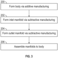
- the heat exchanger body 12 is first formed at step 200 via one or more additive manufacturing processes.
- the inlet manifold 30 is formed at step 202 and the outlet manifold 40 is formed at step 204.
- the inlet manifold 30 and the outlet manifold 40 are formed independently from the heat exchanger body 12, in some embodiments via subtractive manufacturing processes such as machining or milling. Once the inlet manifold 30 and the outlet manifold 40 are formed, they are assembled to the heat exchanger body 12 to define the heat exchanger 10 at step 206.
- the heat exchanger body 12 is formed by additive manufacturing processes, together with rough shapes, such as blocks, at the positions of one or more of the inlet manifold 30 and the outlet manifold 40 at step 300.
- the inlet manifold 30 is formed in place connected to the heat exchanger body 12 at step 302 by one or more subtractive manufacturing processes such as machining or milling performed on the block at the position of the inlet manifold 30.
- the outlet manifold 40 is formed in place connected to the heat exchanger body 12 at step 304 by one or more subtractive manufacturing processes such as machining or milling performed on the block at the position of the outlet manifold 40.
- the heat exchanger body 12, the inlet manifold 30 and the outlet manifold 40 thus define the heat exchanger 10 at step 306.
- the heat exchanger 10 having this hybrid construction, with an additively manufacture heat exchanger body 12 and subtractively manufactured manifolds 30, 40 allows for the manifolds 30, 40 to have a shorter flow length than a manifold formed by additive manufacturing.
- a primary benefit of this configuration is the ability to reduce the overall required hot inlet to outlet (fractal header) length of the heat exchanger 10, which can enable either a more compact unit or increased tube length that can be used to obtain additional heat transfer capability.
Landscapes
- Engineering & Computer Science (AREA)
- Mechanical Engineering (AREA)
- Physics & Mathematics (AREA)
- Thermal Sciences (AREA)
- General Engineering & Computer Science (AREA)
- Chemical & Material Sciences (AREA)
- Manufacturing & Machinery (AREA)
- Materials Engineering (AREA)
- Heat-Exchange Devices With Radiators And Conduit Assemblies (AREA)
Abstract
A heat exchanger (10) includes a heat exchanger body (12) having a plurality of heat exchanger tubes (14), an inlet manifold connected to the heat exchanger body and configured to distribute a flow of fluid from a fluid inlet (28) of the inlet manifold (30) to the plurality of heat exchanger tubes (14), and an outlet manifold (40) connected to the heat exchanger body (12) and configured to collect the flow of fluid from the plurality of heat exchanger tubes (14) and direct the flow of fluid through a fluid outlet (42). The heat exchanger body (12) is formed via one or more additive manufacturing processes, and at least one of the inlet manifold (30) and the outlet manifold (40) is formed via one or more subtractive manufacturing processes.
Description
- Exemplary embodiments pertain to the art of heat exchangers and in particular to the construction of fluid-air heat exchangers having fluid headers.
- Heat exchangers are utilized in a variety of applications, such as cooling of engines or motors, climate control (heating, ventilation and air conditioning systems) or the like. Utilizing additive manufacturing techniques, such as 3D printing or the like, in manufacturing heat exchangers allows for the manufacture of shapes and configurations of heat exchangers not easily achieved via conventional manufacturing operations.
- Utilizing additive manufacturing processes, however, imposes certain geometrical constraints on the heat exchanger configuration. For instance, due to 3D printing constraints, the geometry is limited in maximum horizontal angle to about 45 degrees. This results in longer transition from a header to the high surface area sections of a heat exchanger body, thus lowering overall effectiveness of the heat exchanger (HX), or alternatively requiring additional supports to be incorporated to the structure during manufacture. The additional supports may be difficult to access and remove in the locations inside of the unit once manufacture of the heat exchanger is completed.
- In one exemplary embodiment, a heat exchanger includes a heat exchanger body having a plurality of heat exchanger tubes, an inlet manifold connected to the heat exchanger body and configured to distribute a flow of fluid from a fluid inlet of the inlet manifold to the plurality of heat exchanger tubes, and an outlet manifold connected to the heat exchanger body and configured to collect the flow of fluid from the plurality of heat exchanger tubes and direct the flow of fluid through a fluid outlet. The heat exchanger body is formed via one or more additive manufacturing processes, and at least one of the inlet manifold and the outlet manifold is formed via one or more subtractive manufacturing processes.
- Additionally or alternatively, in this or other embodiments the heat exchanger body includes a plurality of fins connecting heat exchanger tubes of the plurality of heat exchanger tubes.
- Additionally or alternatively, in this or other embodiments the inlet manifold includes a plurality of inlet passages connecting the fluid inlet to the plurality of heat exchanger tubes.
- Additionally or alternatively, in this or other embodiments the plurality of inlet passages includes a plurality of first inlet passages extending from the fluid inlet and a plurality of second inlet passages branching off from the plurality of first inlet passages.
- Additionally or alternatively, in this or other embodiments the outlet manifold includes a plurality of outlet passages connecting the fluid outlet to the plurality of heat exchanger tubes.
- Additionally or alternatively, in this or other embodiments the plurality of outlet passages includes a plurality of first outlet passages extending from the plurality of heat exchanger tubes and a plurality of second outlet passages. Each second outlet passage of the plurality of second outlet passages is fluidly connected to two or more first outlet passages of the plurality of first outlet passages.
- Additionally or alternatively, in this or other embodiments the additive manufacturing processes includes 3D printing.
- Additionally or alternatively, in this or other embodiments the subtractive manufacturing processes includes one or more of machining and milling.
- In another exemplary embodiment, a method of forming a heat exchanger includes forming a heat exchanger body including a plurality of heat exchanger tubes via one or more additive manufacturing processes, and forming at least one of the inlet manifold and the outlet manifold via one or more subtractive manufacturing processes. The inlet manifold is connected to the heat exchanger body and is configured to distribute a flow of fluid from a fluid inlet of the inlet manifold to the plurality of heat exchanger tubes. The outlet manifold is connected to the heat exchanger body and is configured to collect the flow of fluid from the plurality of heat exchanger tubes and direct the flow of fluid through a fluid outlet.
- Additionally or alternatively, in this or other embodiments one of the inlet manifold and the outlet manifold is utilized as a base for forming the heat exchanger body via the one or more additive manufacturing processes.
- Additionally or alternatively, in this or other embodiments a block is formed at the location of one of the inlet manifold and the outlet manifold via one or more additive manufacturing processes simultaneously with the forming of the heat exchanger body. One of the inlet manifold and the outlet manifold are formed from the block via one or more subtractive manufacturing processes.
- Additionally or alternatively, in this or other embodiments a block is formed at the locations of both of the inlet manifold and the outlet manifold via one or more additive manufacturing processes simultaneously with the forming of the heat exchanger body. Both of the inlet manifold and the outlet manifold are formed from the blocks via one or more subtractive manufacturing processes.
- Additionally or alternatively, in this or other embodiments both of the inlet manifold and the outlet manifold are formed separately from the heat exchanger body, and the inlet manifold and the outlet manifold are secured to the heat exchanger body after forming of the heating exchanger body.
- Additionally or alternatively, in this or other embodiments the heat exchanger body includes a plurality of fins connecting heat exchanger tubes of the plurality of heat exchanger tubes.
- Additionally or alternatively, in this or other embodiments the inlet manifold includes a plurality of inlet passages connecting the fluid inlet to the plurality of heat exchanger tubes.
- Additionally or alternatively, in this or other embodiments the plurality of inlet passages includes a plurality of first inlet passages extending from the fluid inlet and a plurality of second inlet passages branching off from the plurality of first inlet passages.
- Additionally or alternatively, in this or other embodiments the outlet manifold includes a plurality of outlet passages connecting the fluid outlet to the plurality of heat exchanger tubes.
- Additionally or alternatively, in this or other embodiments the plurality of outlet passages includes a plurality of first outlet passages extending from the plurality of heat exchanger tubes and a plurality of second outlet passages. Each second outlet passage of the plurality of second outlet passages is fluidly connected to two or more first outlet passages of the plurality of first outlet passages.
- Additionally or alternatively, in this or other embodiments the additive manufacturing processes includes 3D printing.
- Additionally or alternatively, in this or other embodiments the subtractive manufacturing processes includes one or more of machining and milling.
- The following descriptions should not be considered limiting in any way. With reference to the accompanying drawings, like elements are numbered alike:
-
FIG. 1 is a schematic illustration of an embodiment of a heat exchanger; -
FIG. 2 is a schematic illustration of a first exemplary method of forming a heat exchanger; -
FIG. 3 is a schematic illustration of a second exemplary method of forming a heat exchanger; and -
FIG. 4 is a schematic illustration of a third exemplary method of forming a heat exchanger. - A detailed description of one or more embodiments of the disclosed apparatus and method are presented herein by way of exemplification and not limitation with reference to the Figures.
- Referring now to
FIG. 1 , illustrated is an embodiment of aheat exchanger 10. Theheat exchanger 10 includes aheat exchanger body 12 having a plurality ofbody tubes 14 extending from afirst body end 16 to asecond body end 18, opposite thefirst body end 16. In some embodiments, thebody tubes 14 extend linearly from the first body end 16 to thesecond body end 18, while in other embodiments, such as shown inFIG. 1 , thebody tubes 14 extend curvilinearly from thefirst body end 16 to the second body end 18. In yet other embodiments, thebody tubes 14 extend a combination of linearly and curvilinearly along their length from the first body end 16 to the second body end 18. Thebody tubes 14 may have a constant size and shape along their length, or alternatively one or more of the tube size and tube shape may vary along their length. - In some embodiments, such as shown in
FIG. 1 , theheat exchanger body 12 includes a plurality of fins 20. The fins 20 may extend betweenadjacent body tubes 14 and along a length of thebody tubes 14 to interconnect thebody tubes 14 and increase surface area of theheat exchanger body 12 and improve effectiveness of theheat exchanger 10. Thebody tubes 14 are configured to direct a flow offluid 22 through theheat exchanger body 12. A flow ofair 24 is directed across thebody tubes 14 by, for example, afan 26, and the flow offluid 22 is cooled, or alternatively heated, via exchange of thermal energy between the flow ofair 24 and the flow offluid 22 via theheat exchanger body 12. - The flow of
fluid 22 enters theheat exchanger 10 through afluid inlet 28 and is distributed to thebody tubes 14 by flowing through aninlet manifold 30. In some embodiments, such as illustrated inFIG. 1 , theinlet manifold 30 includes aninlet manifold body 32 at which thefluid inlet 28 is located, and a plurality offirst inlet passages 34 branching from theinlet manifold body 32. A plurality ofsecond inlet passages 36 branch from each of thefirst inlet passages 34, and a plurality ofthird inlet passages 38 branch from each of thesecond inlet passages 36. The plurality ofthird inlet passages 38 are each connected to abody tube 14 of the plurality ofbody tubes 14 to direct the flow offluid 22 into thebody tubes 14. Theinlet passages fluid 22 into each of thebody tubes 14, in some embodiments the selected proportions are equal amounts of the flow offluid 22 into each of thebody tubes 14. One skilled in the art will readily appreciate that while theinlet manifold 30 described herein distributes the flow offluid 22 to thebody tubes 14 via theinlet passages inlet manifold 30 to distribute the flow offluid 14 into thebody tubes 14. - Similarly, the flow of
fluid 22 exits thebody tubes 14 and is collected at anoutlet manifold 40 before exiting theheat exchanger 10 through afluid outlet 42. Theoutlet manifold 40 includes a plurality offirst outlet passages 44, eachfirst outlet passage 44 connected to abody tube 14 of theheat exchanger body 12 to collect the flow offluid 22 from thebody tubes 14. A plurality ofsecond outlet passages 46 collect the flow offluid 22 from thefirst outlet passages 44, where eachsecond outlet passage 46 is connected to a number offirst outlet passages 44. A plurality ofthird outlet passages 48 collect the flow offluid 22 from thesecond outlet passages 46, where eachthird outlet passage 48 is connected to a number ofsecond outlet passages 46. Thethird outlet passages 48 are connected to anoutlet manifold body 50, which directs the flow offluid 22 from thethird outlet passages 48 and out of thefluid outlet 42. - While manufacturing components such as
heat exchangers 10 by additive manufacturing methods such as 3D printing can be advantageous in many respects, the use of additive manufacturing places certain geometric constraints on theheat exchanger 10, such as in the construction of theinlet manifold 30 and theoutlet manifold 40. To overcome these geometric constraints, a hybrid construction of theheat exchanger 10 is utilized. - Referring to
FIG. 2 , in a first exemplary method, theinlet manifold 30 and theoutlet manifold 40 are formed not by additive manufacturing, but by subtractive manufacturing methods, such as machining or milling atstep 100 to arrive at the completed configurations of theinlet manifold 30 and the outlet manifold. In the embodiment ofFIG. 2 , one of the manifolds, for example, theinlet manifold 30, is utilized as a manufacturing base for theheat exchanger body 12 atstep 102, which is then formed onto the inlet manifold atstep 104 by one or more additive manufacturing processes, such as 3D printing. The additive manufacturing processes form thebody tubes 14 and the fins 20 of theheat exchanger body 12 onto theinlet manifold 30. Once theheat exchanger body 12 is formed on theinlet manifold 30, theoutlet manifold 40, which may be formed not by additive manufacturing, but by machining or milling, is assembled to theheat exchanger body 12 to form theheat exchanger 10 atstep 106. - Referring to
FIG. 3 , another exemplary method of forming theheat exchanger 10 is illustrated. In this second exemplary method, theheat exchanger body 12 is first formed atstep 200 via one or more additive manufacturing processes. Theinlet manifold 30 is formed atstep 202 and theoutlet manifold 40 is formed atstep 204. Theinlet manifold 30 and theoutlet manifold 40 are formed independently from theheat exchanger body 12, in some embodiments via subtractive manufacturing processes such as machining or milling. Once theinlet manifold 30 and theoutlet manifold 40 are formed, they are assembled to theheat exchanger body 12 to define theheat exchanger 10 atstep 206. - Referring now to
FIG. 4 , yet another exemplary method of forming theheat exchanger 10 is illustrated. In this third exemplary embodiment, theheat exchanger body 12 is formed by additive manufacturing processes, together with rough shapes, such as blocks, at the positions of one or more of theinlet manifold 30 and theoutlet manifold 40 atstep 300. Once theheat exchanger body 12 is formed, then theinlet manifold 30 is formed in place connected to theheat exchanger body 12 atstep 302 by one or more subtractive manufacturing processes such as machining or milling performed on the block at the position of theinlet manifold 30. Similarly, theoutlet manifold 40 is formed in place connected to theheat exchanger body 12 atstep 304 by one or more subtractive manufacturing processes such as machining or milling performed on the block at the position of theoutlet manifold 40. Theheat exchanger body 12, theinlet manifold 30 and theoutlet manifold 40 thus define theheat exchanger 10 atstep 306. - The
heat exchanger 10 having this hybrid construction, with an additively manufactureheat exchanger body 12 and subtractively manufacturedmanifolds manifolds heat exchanger 10, which can enable either a more compact unit or increased tube length that can be used to obtain additional heat transfer capability. - The term "about" is intended to include the degree of error associated with measurement of the particular quantity based upon the equipment available at the time of filing the application.
- The terminology used herein is for the purpose of describing particular embodiments only and is not intended to be limiting of the present disclosure. As used herein, the singular forms "a", "an" and "the" are intended to include the plural forms as well, unless the context clearly indicates otherwise. It will be further understood that the terms "comprises" and/or "comprising," when used in this specification, specify the presence of stated features, integers, steps, operations, elements, and/or components, but do not preclude the presence or addition of one or more other features, integers, steps, operations, element components, and/or groups thereof.
- While the present disclosure has been described with reference to an exemplary embodiment or embodiments, it will be understood by those skilled in the art that various changes may be made and equivalents may be substituted for elements thereof without departing from the scope of the present disclosure. In addition, many modifications may be made to adapt a particular situation or material to the teachings of the present disclosure without departing from the essential scope thereof. Therefore, it is intended that the present disclosure not be limited to the particular embodiment disclosed as the best mode contemplated for carrying out this present disclosure, but that the present disclosure will include all embodiments falling within the scope of the claims.
Claims (15)
- A heat exchanger, comprising:a heat exchanger body including a plurality of heat exchanger tubes;an inlet manifold connected to the heat exchanger body and configured to distribute a flow of fluid from a fluid inlet of the inlet manifold to the plurality of heat exchanger tubes; andan outlet manifold connected to the heat exchanger body and configured to collect the flow of fluid from the plurality of heat exchanger tubes and direct the flow of fluid through a fluid outlet;wherein:the heat exchanger body is formed via one or more additive manufacturing processes; andat least one of the inlet manifold and the outlet manifold is formed via one or more subtractive manufacturing processes.
- The heat exchanger of claim 1, wherein the heat exchanger body includes a plurality of fins connecting heat exchanger tubes of the plurality of heat exchanger tubes.
- The heat exchanger of claim 1 or 2, wherein the inlet manifold includes a plurality of inlet passages connecting the fluid inlet to the plurality of heat exchanger tubes.
- The heat exchanger of claim 3, wherein the plurality of inlet passages includes a plurality of first inlet passages extending from the fluid inlet and a plurality of second inlet passages branching off from the plurality of first inlet passages.
- The heat exchanger of any preceding claim, wherein the outlet manifold includes a plurality of outlet passages connecting the fluid outlet to the plurality of heat exchanger tubes.
- The heat exchanger of claim 5, wherein the plurality of outlet passages includes a plurality of first outlet passages extending from the plurality of heat exchanger tubes and a plurality of second outlet passages, each second outlet passage of the plurality of second outlet passages fluidly connected to two or more first outlet passages of the plurality of first outlet passages.
- The heat exchanger of any preceding claim, wherein the additive manufacturing processes includes 3D printing.
- The heat exchanger of any preceding claim, wherein the subtractive manufacturing processes includes one or more of machining and milling.
- A method of forming a heat exchanger comprising:forming a heat exchanger body including a plurality of heat exchanger tubes via one or more additive manufacturing processes; andforming at least one of the inlet manifold and the outlet manifold via one or more subtractive manufacturing processes, wherein:the inlet manifold is connected to the heat exchanger body and is configured to distribute a flow of fluid from a fluid inlet of the inlet manifold to the plurality of heat exchanger tubes; andthe outlet manifold is connected to the heat exchanger body and is configured to collect the flow of fluid from the plurality of heat exchanger tubes and direct the flow of fluid through a fluid outlet.
- The method of claim 9, wherein one of the inlet manifold and the outlet manifold is utilized as a base for forming the heat exchanger body via the one or more additive manufacturing processes.
- The method of claim 9 or 10, further comprising:forming a block at the location of one of the inlet manifold and the outlet manifold via one or more additive manufacturing processes simultaneously with the forming of the heat exchanger body; andforming one of the inlet manifold and the outlet manifold from the block via one or more subtractive manufacturing processes, optionally further comprising:forming a block at the locations of both of the inlet manifold and the outlet manifold via one or more additive manufacturing processes simultaneously with the forming of the heat exchanger body; andforming both of the inlet manifold and the outlet manifold from the blocks via one or more subtractive manufacturing processes.
- The method of claim 9, 10 or 11, further comprising:forming both of the inlet manifold and the outlet manifold separately from the heat exchanger body; andsecuring the inlet manifold and the outlet manifold to the heat exchanger body after forming of the heating exchanger body; and/orwherein the heat exchanger body includes a plurality of fins connecting heat exchanger tubes of the plurality of heat exchanger tubes.
- The method of any of claims 9 to 12, wherein the inlet manifold includes a plurality of inlet passages connecting the fluid inlet to the plurality of heat exchanger tubes, optionally,
wherein the plurality of inlet passages includes a plurality of first inlet passages extending from the fluid inlet and a plurality of second inlet passages branching off from the plurality of first inlet passages. - The method of any of claims 9 to 13, wherein the outlet manifold includes a plurality of outlet passages connecting the fluid outlet to the plurality of heat exchanger tubes, optionally,
wherein the plurality of outlet passages includes a plurality of first outlet passages extending from the plurality of heat exchanger tubes and a plurality of second outlet passages, each second outlet passage of the plurality of second outlet passages fluidly connected to two or more first outlet passages of the plurality of first outlet passages. - The method of any of claims 9 to 14, wherein the additive manufacturing processes includes 3D printing; and/or
wherein the subtractive manufacturing processes includes one or more of machining and milling.
Applications Claiming Priority (1)
| Application Number | Priority Date | Filing Date | Title |
|---|---|---|---|
| US18/491,909 US20250129990A1 (en) | 2023-10-23 | 2023-10-23 | Heat exchanger and header construction |
Publications (1)
| Publication Number | Publication Date |
|---|---|
| EP4545301A1 true EP4545301A1 (en) | 2025-04-30 |
Family
ID=92932643
Family Applications (1)
| Application Number | Title | Priority Date | Filing Date |
|---|---|---|---|
| EP24203737.2A Pending EP4545301A1 (en) | 2023-10-23 | 2024-09-30 | Heat exchanger and header construction |
Country Status (2)
| Country | Link |
|---|---|
| US (1) | US20250129990A1 (en) |
| EP (1) | EP4545301A1 (en) |
Families Citing this family (2)
| Publication number | Priority date | Publication date | Assignee | Title |
|---|---|---|---|---|
| US20240240881A1 (en) * | 2023-01-17 | 2024-07-18 | Hamilton Sundstrand Corporation | Heat exchanger having compliant manifolds |
| US12516893B2 (en) * | 2023-02-14 | 2026-01-06 | Hamilton Sundstrand Corporation | Heat exchangers with flow-modifying heat exchanger core tubes |
Citations (6)
| Publication number | Priority date | Publication date | Assignee | Title |
|---|---|---|---|---|
| US20130236299A1 (en) * | 2012-03-06 | 2013-09-12 | Honeywell International Inc. | Tubular heat exchange systems |
| US9976815B1 (en) * | 2014-02-20 | 2018-05-22 | Hrl Laboratories, Llc | Heat exchangers made from additively manufactured sacrificial templates |
| US20200003497A1 (en) * | 2018-06-29 | 2020-01-02 | The Boeing Company | Additively manufactured heat transfer device |
| US10695836B2 (en) * | 2017-02-17 | 2020-06-30 | Hs Marston Aerospace Limited | Method of manufacturing a heat exchanger |
| US20220034592A1 (en) * | 2020-07-29 | 2022-02-03 | Hamilton Sundstrand Corporation | Annular heat exchanger |
| US11396069B2 (en) * | 2019-11-21 | 2022-07-26 | Hamilton Sundstrand Corporation | Integrated horn structures for heat exchanger headers |
Family Cites Families (1)
| Publication number | Priority date | Publication date | Assignee | Title |
|---|---|---|---|---|
| US10619949B2 (en) * | 2016-04-12 | 2020-04-14 | United Technologies Corporation | Light weight housing for internal component with integrated thermal management features and method of making |
-
2023
- 2023-10-23 US US18/491,909 patent/US20250129990A1/en active Pending
-
2024
- 2024-09-30 EP EP24203737.2A patent/EP4545301A1/en active Pending
Patent Citations (6)
| Publication number | Priority date | Publication date | Assignee | Title |
|---|---|---|---|---|
| US20130236299A1 (en) * | 2012-03-06 | 2013-09-12 | Honeywell International Inc. | Tubular heat exchange systems |
| US9976815B1 (en) * | 2014-02-20 | 2018-05-22 | Hrl Laboratories, Llc | Heat exchangers made from additively manufactured sacrificial templates |
| US10695836B2 (en) * | 2017-02-17 | 2020-06-30 | Hs Marston Aerospace Limited | Method of manufacturing a heat exchanger |
| US20200003497A1 (en) * | 2018-06-29 | 2020-01-02 | The Boeing Company | Additively manufactured heat transfer device |
| US11396069B2 (en) * | 2019-11-21 | 2022-07-26 | Hamilton Sundstrand Corporation | Integrated horn structures for heat exchanger headers |
| US20220034592A1 (en) * | 2020-07-29 | 2022-02-03 | Hamilton Sundstrand Corporation | Annular heat exchanger |
Also Published As
| Publication number | Publication date |
|---|---|
| US20250129990A1 (en) | 2025-04-24 |
Similar Documents
| Publication | Publication Date | Title |
|---|---|---|
| US20250129990A1 (en) | Heat exchanger and header construction | |
| EP3604998A1 (en) | Counter flow heat exchanger | |
| CN101611285B (en) | associated heat exchanger | |
| US6705386B2 (en) | Serpentine heat exchanger | |
| EP1395786B1 (en) | Condenser for air cooled chillers | |
| US20100218930A1 (en) | System and method for constructing heat exchanger | |
| JPH0315117B2 (en) | ||
| EP3388769A1 (en) | Heat exchanger assembly | |
| US5176200A (en) | Method of generating heat exchange | |
| CN102192672A (en) | Flat tube heat exchanger structure and assembling method thereof | |
| JP2013234801A (en) | Heat exchanger and vehicle air conditioning device | |
| WO2005022064A1 (en) | Aluminum heat exchanger and method of making thereof | |
| EP1892492A3 (en) | Heat exchange module, in particular for an automobile vehicle, comprising a main radiator and a secondary radiator, and system comprising this module | |
| CN102192673A (en) | Flat-tube heat exchanger structure and assembling method thereof | |
| CN104080556B (en) | For the manufacture of the method for heat exchanger and the heat exchanger that obtained by described method, for performing pattern and the pipeline extension fixture of described method | |
| US7051796B2 (en) | Heat exchanger | |
| EP0683371A1 (en) | Heat exchanger | |
| CN220982020U (en) | Multi-medium micro-channel heat exchanger | |
| JP4536243B2 (en) | Heat exchanger for air conditioning | |
| EP3193127A1 (en) | Thermal stress relief for heat sinks | |
| JP2586753Y2 (en) | Heat exchanger | |
| CN117128786A (en) | Heat exchangers and heat exchange equipment | |
| EP4194786B1 (en) | Additive airfoil heat exchanger | |
| EP3137836A1 (en) | Improved heat exchanger | |
| CN100374807C (en) | heat exchanger |
Legal Events
| Date | Code | Title | Description |
|---|---|---|---|
| PUAI | Public reference made under article 153(3) epc to a published international application that has entered the european phase |
Free format text: ORIGINAL CODE: 0009012 |
|
| STAA | Information on the status of an ep patent application or granted ep patent |
Free format text: STATUS: THE APPLICATION HAS BEEN PUBLISHED |
|
| AK | Designated contracting states |
Kind code of ref document: A1 Designated state(s): AL AT BE BG CH CY CZ DE DK EE ES FI FR GB GR HR HU IE IS IT LI LT LU LV MC ME MK MT NL NO PL PT RO RS SE SI SK SM TR |
|
| STAA | Information on the status of an ep patent application or granted ep patent |
Free format text: STATUS: REQUEST FOR EXAMINATION WAS MADE |
|
| 17P | Request for examination filed |
Effective date: 20251027 |