EP4545249A1 - Socket for fastening a ball stud bolt - Google Patents
Socket for fastening a ball stud bolt Download PDFInfo
- Publication number
- EP4545249A1 EP4545249A1 EP23206551.6A EP23206551A EP4545249A1 EP 4545249 A1 EP4545249 A1 EP 4545249A1 EP 23206551 A EP23206551 A EP 23206551A EP 4545249 A1 EP4545249 A1 EP 4545249A1
- Authority
- EP
- European Patent Office
- Prior art keywords
- stud bolt
- ball stud
- recess
- socket
- cutout
- Prior art date
- Legal status (The legal status is an assumption and is not a legal conclusion. Google has not performed a legal analysis and makes no representation as to the accuracy of the status listed.)
- Pending
Links
Images

Classifications
-
- B—PERFORMING OPERATIONS; TRANSPORTING
- B25—HAND TOOLS; PORTABLE POWER-DRIVEN TOOLS; MANIPULATORS
- B25B—TOOLS OR BENCH DEVICES NOT OTHERWISE PROVIDED FOR, FOR FASTENING, CONNECTING, DISENGAGING, OR HOLDING
- B25B13/00—Spanners; Wrenches
- B25B13/02—Spanners; Wrenches with rigid jaws
- B25B13/06—Spanners; Wrenches with rigid jaws of socket type
- B25B13/065—Spanners; Wrenches with rigid jaws of socket type characterised by the cross-section of the socket
-
- B—PERFORMING OPERATIONS; TRANSPORTING
- B25—HAND TOOLS; PORTABLE POWER-DRIVEN TOOLS; MANIPULATORS
- B25B—TOOLS OR BENCH DEVICES NOT OTHERWISE PROVIDED FOR, FOR FASTENING, CONNECTING, DISENGAGING, OR HOLDING
- B25B13/00—Spanners; Wrenches
- B25B13/48—Spanners; Wrenches for special purposes
- B25B13/50—Spanners; Wrenches for special purposes for operating on work of special profile, e.g. pipes
- B25B13/5091—Spanners; Wrenches for special purposes for operating on work of special profile, e.g. pipes for operating on wing nuts, hooks, eye hooks or the like
Definitions
- the invention relates to a wrench, in particular a socket wrench for a ball stud bolt.
- Ball stud bolts are commonly used in wide range of applications such as automotive industry, aerospace industry, medical equipment, agricultural machinery, etc. In automotive industry, the ball stud bolt is extensively used for applications such as steering or suspension systems, to allow movement and flexibility while maintaining a secure connection.
- the ball stud bolt is a type of fastener made up of a threaded portion and a non-threaded portion. The non threaded portion further includes a ball, a neck and a torquing surface.
- the ball is a spherical component that allows rotation inside a housing of another component and provides a flexible connection point, while the threaded stud is generally fastened to a surface or another threaded component.
- the ball stud bolt's ability to pivot and allow rotation ensures that components can adapt to changing angles and forces enhancing overall performance and safety of mechanical system.
- the object of the invention is to develop a tool that allows the operator to comfortably apply torque to the ball stud bolt while also reducing the time required for the process and enhancing the accuracy.
- a ball stud bolt comprises a threaded portion and a non-threaded portion wherein the non-threaded portion comprises a ball, a neck and a torquing surface.
- a socket for torquing the ball stud bolt comprises a cylindrical body having a working end, a drive end and an elongated outer sidewall.
- the working end comprises a recess configured to receive the non-threaded portion of the ball stud bolt.
- the drive end comprises an aperture where a driving member of a torque wrench is detachably attached to drive the socket.
- the elongated outer sidewall is located between the working end and the drive end.
- a cutout is provided in the outer sidewall of the working end for the entry of the ball stud bolt into the recess. The cutout has a first section and a second section wherein width of the first section is smaller than width of the second section.
- an unengaged position refers to when the ball stud bolt and socket are in separated position, whereas an engaged position refers to when they are securely connected.
- a transition position is the intermediate stage between the engaged and the unengaged position.
- the cutout in the outer sidewall of the socket allows easy entry of the non-threaded portion of a ball stud bolt into the recess in the transition position. This enables a socket wrench to be used for torquing a ball stud having a larger diameter of the ball than the width of the torquing surface of the ball stud bolt.
- the socket In the engaged position, the socket provides a grip over the torquing surface, hence, the wrench does not slip off from the torquing surface unlike the open-ended wrench.
- the aperture On the driving end of the socket, the aperture may allow the socket to be easily coupled to the driving member of the torque wrench. If the structural arrangement does not allow the driving member of the torque wrench to be directly coupled to the socket, an adapter may be used to couple them together.
- the torque wrench can be with a cord or without a cord.
- Use of the torque wrench for torquing the ball stud bolt ensures uniform and defined torque to be applied across all the ball stud bolts. This improves the comfort and the accuracy of an operation, and drastically reduces the time required for the operation.
- the person skilled in the art will appreciate that the torque wrench can be operated electrically, hydraulically, manually or by any other means.
- the socket according to the invention is designed for a ball stud bolt having diameter of the ball more than the width of the torquing surface.
- the socket may also be used for other configurations of the bolts e.g a flat head bolt or a ball stud bolt having diameter of the ball smaller than the width of the torquing surface, etc.
- the socket is made up of a metal, however, other material such as plastic can also be used for manufacturing the socket.
- the socket is used for tightening as well as loosening the ball stud bolt.
- the cutout covers less than half the circumference of the socket.
- the socket is designed such that the cutout allows the entry of the ball and the neck of the ball stud bolt into the recess in the transition position, at the same time the recess offers ample contact area with torquing surface in the engaged position. This ensures the socket does not slip off during the operation.
- the first section of the cutout is rectangular to allow entry of the neck of the ball stud bolt into the recess in the transition position.
- Width of the first section of the cutout is less than width of the torquing surface and/or diameter of the ball of the ball stud bolt to be received in the socket. Hence, the torquing surface of the ball stud bolt cannot enter the recess through first section of the cutout.
- the second section of the cutout is curved to allow entry of the ball into the recess in the transition position.
- the person skilled in the art will appreciate different profiles of the second section based on the corresponding profiles of the head of the bolt. If instead of a spherical ball the head of bolt is cubical, accordingly the profile of the second section of the cutout can be rectangular.
- the recess comprises a first portion, a second portion and a collar.
- the first portion of the recess is configured to receive the torquing surface of the ball stud bolt in the engaged position.
- the first portion of the recess corresponds to the shape of the torquing surface of the ball stud bolt to be received.
- the torquing surface of the ball stud bolt have two flat surfaces connected by a curve. Accordingly, to provide the secured connection in the engaged position the first portion of the recess has two opposite flat surfaces joined together by a curve on a distal end of the cutout.
- An arresting unit is defined on each of the flat surfaces towards the cutout end of the first portion of the recess.
- the arresting units lock the ball stud bolt in the recess in the engaged position restricting slipping-off of the socket.
- the arresting units has length equal to the thickness of the outer sidewall. In the transition position, the arresting units do not allow the torquing surface of the ball stud bolt to enter the recess from the first section of the cutout.
- the second portion of the recess has spherical shape.
- Shape of the second portion of the recess may correspond to shape of the head of the bolt. The person skilled in the art will appreciate different shapes of the second portion of the recess. If the head of the bolt is cubical, the shape of the second portion of the recess will also be cubical. Although, spherical shape of the second portion of the recess may also receive the cubical head of the ball stud bolt.
- the torque is applied to the ball stud bolt from the torquing surface. Hence, a secured fitting of the torquing surface of the ball stud bolt is required with the first portion of the recess.
- the second portion of the recess may not assist in torquing.
- the secured fitting of the ball of the ball stud bolt may not be required with the second portion of the recess.
- the dimensions of the second portion of the recess may be larger than the dimensions of the ball of the ball stud bolt.
- a collar is positioned between the first portion and the second portion of the recess. The collar provides proper seat for the torquing surface in the engaged position.
- the longitudinal depth of the recess from the working end is more than the longitudinal depth of the cutout from the working end.
- the bottommost point of the second portion of the recess from the working end is deeper than the bottommost point of the cutout from the working end. The difference in depth allows the torquing surface to move from the transition position to the engaged position.
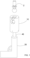
- Fig. 1 shows a socket 10 according to the invention coupled with a driving member of a torque wrench 26.
- the socket 10 is used to torque a ball stud bolt 2.
- the ball stud bolt 2 comprises a threaded portion 4 and a non-treaded portion 6.
- the non-threaded portion 6 further comprises a ball 8, a torquing surface 12 and a neck 11 between the ball 8 and the torquing surface 12.
- the socket 10 is engaged with torquing surface 12 to tighten the ball stud bolt 2.
- the diameter of the ball 8 is larger than the width of the torquing surface 12.
- a conventional socket wrench cannot be used for torquing the ball stud bolt 2.
- the larger diameter of the ball 8 do not allow the socket to reach to the torquing surface 12.
- the socket 10 shown in Fig. 2 addresses the above-mentioned challenge by providing a cutout 28 as described in this invention.
- the socket 10 comprises a cylindrical body 14 having a working end 16, a drive end 18 and an elongated outer sidewall 20 between the working end 16 and the drive end 18.
- the working end 16 further comprises a recess 22 configured to receive the non-threaded portion 6 of the ball stud bolt 2.
- the drive end 18 comprises an aperture 24 to detachably attach the driving member of the torque wrench 26.
- the driving member of the torque wrench 26 can be directly coupled to the socket 10 or a coupling member 46 may be used to couple the socket 10 and the driving member of the torque wrench 26.
- the torque wrench 26 provides the torque to the socket 10 for fastening the ball stud bolt 2.
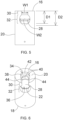
- the cutout 28 is provided in the outer sidewall 20 of the working end 16 for entry of the ball stud bolt 2 into the recess 22.
- the cutout 28 covers less than half circumference of the outer sidewall 20 of the socket 10.
- the cutout 28 has a first section 30 and a second section 32.
- the first section 30 of the cutout 28 is rectangular to allow entry of the neck 11 of the ball stud bolt 2 into the recess 22.
- the second section 32 of the cutout 28 is curved to allow entry of the ball 8 of the ball stud bolt 2 into the recess 22.
- the width of the first section W1 of the cutout 28 is smaller than width of the second section W2 of the cutout 28. Further, width of the first section W1 of the cutout 28 is less than the width of the torquing surface 12 and/or diameter of the ball 8 of the ball stud bolt 2 to be received in the socket 10.
- the recess 22 is defined to receive the non-threaded portion 6 of the ball stud bolt 2.
- the recess 22 comprises a first portion 34, a second portion 36 and a collar 38.
- the first portion 34 of the recess 22 corresponds to the shape of the torquing surface 12 of the ball stud bolt 2 to be received.
- the first portion 34 has two opposite flat surfaces 40 joined together by a curve 42 on a distal end of the cutout 28. Each of the flat surface 40 has an arresting unit 44 towards the cutout 28.
- the first portion 34 is configured to receive the torquing surface 12 of the ball stud bolt 2 in the engaged position.
- the arresting units 44 lock the torquing surface 12 of the ball stud bolt 2 in the first potion.
- the second portion 36 of the recess 22 is defined to receive the ball 8 of the ball stud bolt 2 in the engaged position.
- the second portion 36 is spherical. As shown in fig. 5 , the bottommost point of the second portion 36 of the recess 22 from the working end is lower than the bottommost point of the cutout 28 from the working end. Hence, the longitudinal depth D2 of the recess 22 from the working end 16 is more than the longitudinal depth D1 of the cutout 28 from the working end 16.
- a collar 38 is positioned between the first portion 34 and the second portion 36 of the recess 22. The collar 38 supports the neck 11 of the ball stud bolt 2 in the engaged position.
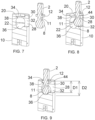
- Figs. 7-9 explain the step-by-step process of engagement of the socket 10 with the ball stud bolt 2.
- Fig. 7 shows the unengaged position of the socket 10 and the ball stud bolt 2.
- Fig. 8 shows the transition between the unengaged position and the engaged position. In the transition position, the ball 8 and the neck 11 of the ball stud bolt 2 enters the recess 22 of the socket 10 through a cutout 28. The ball 8 of the ball stud bolt 2 enters through second section 32 of the cutout 28 and the neck 11 of the ball stud bolt 2 enters through first section 30 of the cutout 28.
- the torquing surface 12 of the ball stud bolt 2 is more than width of the first section 30 of the cutout, the torquing surface 12 cannot enter through the cutout 28 whereas it slides across the width of the outer sidewall 20.
- the socket 10 is moved toward the ball stud bolt 2 in the longitudinal direction to lock in the engaged position as shown in Fig. 9 .
- the collar 38 supports the neck 11 of the ball stud bolt 2 and also provides a platform for the torquing surface 12.
- the arresting unit 44 locks the ball stud bolt 2 in engaged position and do not allow it to slip off.
- the first portion 34 of the recess 22 provide contact area between the socket 10 and the torquing surface 12 of the ball stud bolt 2 to torque.
- the torque wrench 26 can be turned on to torque the ball stud bolt 2. Torque is transmitted to the ball stud bolt 2 through the contact between the torquing surface 12 of the ball stud bolt and the first portion 34 of the socket 10. The torque wrench 26 apply a defined torque for fastening the ball stud bolt 2.
- the disengagement of the ball stud bolt 2 and socket 10 is started.
- the socket 10 is pulled back till the torquing surface 12 comes out of the first portion 34 of the recess 22.
- the socked is disengaged from the ball stud bolts by removing the ball 8 and the neck 11 through the cutout 28.
- the operator may proceed to fasten the next ball stud bolt 2. Since, the torque wrench 26 is used, uniform torque is applied across all the ball stud bolts 2.
- socket 10 allows the operator to comfortably apply defined uniform torque to the ball stud bolts 2 while also reducing the time required for the process and enhancing the accuracy.
Landscapes
- Engineering & Computer Science (AREA)
- Mechanical Engineering (AREA)
- Pivots And Pivotal Connections (AREA)
Abstract
Description
- The invention relates to a wrench, in particular a socket wrench for a ball stud bolt.
- Ball stud bolts are commonly used in wide range of applications such as automotive industry, aerospace industry, medical equipment, agricultural machinery, etc. In automotive industry, the ball stud bolt is extensively used for applications such as steering or suspension systems, to allow movement and flexibility while maintaining a secure connection. The ball stud bolt is a type of fastener made up of a threaded portion and a non-threaded portion. The non threaded portion further includes a ball, a neck and a torquing surface. The ball is a spherical component that allows rotation inside a housing of another component and provides a flexible connection point, while the threaded stud is generally fastened to a surface or another threaded component. The ball stud bolt's ability to pivot and allow rotation ensures that components can adapt to changing angles and forces enhancing overall performance and safety of mechanical system.
- However, fastening the ball stud bolt on the surface has always been a challenge. The diameter of the ball is more than the width of the torquing surface. Hence, a conventional socket wrench cannot be used, as the socket cannot reach to the torquing surface. The larger diameter of ball blocks the way of socket to reach to the torquing surface. At present, a manually operated open ended wrench is used to torque the ball stud bolt. Use of manually operated open-ended wrench has certain limitations. The wrench head often slips off from the torquing surface. This leads to discomfort for the operator and results in a time-consuming process. Also, since the process is manual, the operator does not understand how much torque has already been applied. Hence, defined and uniform torque may not be applied to different ball stud bolts. This results in less accuracy in torquing the ball stud bolts. Furthermore, a torque machine cannot be used for torquing the ball stud bolt.
- Hence, the object of the invention is to develop a tool that allows the operator to comfortably apply torque to the ball stud bolt while also reducing the time required for the process and enhancing the accuracy.
- This object is achieved by a socket wrench for a ball stud bolt with the features of claim 1.
- A ball stud bolt comprises a threaded portion and a non-threaded portion wherein the non-threaded portion comprises a ball, a neck and a torquing surface. A socket for torquing the ball stud bolt comprises a cylindrical body having a working end, a drive end and an elongated outer sidewall. The working end comprises a recess configured to receive the non-threaded portion of the ball stud bolt. The drive end comprises an aperture where a driving member of a torque wrench is detachably attached to drive the socket. The elongated outer sidewall is located between the working end and the drive end. A cutout is provided in the outer sidewall of the working end for the entry of the ball stud bolt into the recess. The cutout has a first section and a second section wherein width of the first section is smaller than width of the second section.
- In the further description of the invention, an unengaged position refers to when the ball stud bolt and socket are in separated position, whereas an engaged position refers to when they are securely connected. A transition position is the intermediate stage between the engaged and the unengaged position.
- The cutout in the outer sidewall of the socket allows easy entry of the non-threaded portion of a ball stud bolt into the recess in the transition position. This enables a socket wrench to be used for torquing a ball stud having a larger diameter of the ball than the width of the torquing surface of the ball stud bolt. In the engaged position, the socket provides a grip over the torquing surface, hence, the wrench does not slip off from the torquing surface unlike the open-ended wrench. On the driving end of the socket, the aperture may allow the socket to be easily coupled to the driving member of the torque wrench. If the structural arrangement does not allow the driving member of the torque wrench to be directly coupled to the socket, an adapter may be used to couple them together. The torque wrench can be with a cord or without a cord. Use of the torque wrench for torquing the ball stud bolt ensures uniform and defined torque to be applied across all the ball stud bolts. This improves the comfort and the accuracy of an operation, and drastically reduces the time required for the operation. The person skilled in the art will appreciate that the torque wrench can be operated electrically, hydraulically, manually or by any other means.
- The socket according to the invention is designed for a ball stud bolt having diameter of the ball more than the width of the torquing surface. However, the person skilled in the art will appreciate that the socket may also be used for other configurations of the bolts e.g a flat head bolt or a ball stud bolt having diameter of the ball smaller than the width of the torquing surface, etc. The socket is made up of a metal, however, other material such as plastic can also be used for manufacturing the socket. The socket is used for tightening as well as loosening the ball stud bolt.
- Additional embodiments of the hitch are subject to the dependent claims.
- According to one of the exemplary embodiments, the cutout covers less than half the circumference of the socket. The socket is designed such that the cutout allows the entry of the ball and the neck of the ball stud bolt into the recess in the transition position, at the same time the recess offers ample contact area with torquing surface in the engaged position. This ensures the socket does not slip off during the operation.
- The first section of the cutout is rectangular to allow entry of the neck of the ball stud bolt into the recess in the transition position. However, the person skilled in the art will appreciate different profiles of the first section based on the corresponding profiles of the neck of the ball stud bolt. Width of the first section of the cutout is less than width of the torquing surface and/or diameter of the ball of the ball stud bolt to be received in the socket. Hence, the torquing surface of the ball stud bolt cannot enter the recess through first section of the cutout.
- The second section of the cutout is curved to allow entry of the ball into the recess in the transition position. However, the person skilled in the art will appreciate different profiles of the second section based on the corresponding profiles of the head of the bolt. If instead of a spherical ball the head of bolt is cubical, accordingly the profile of the second section of the cutout can be rectangular.
- Further, the recess comprises a first portion, a second portion and a collar. The first portion of the recess is configured to receive the torquing surface of the ball stud bolt in the engaged position. The first portion of the recess corresponds to the shape of the torquing surface of the ball stud bolt to be received. The torquing surface of the ball stud bolt have two flat surfaces connected by a curve. Accordingly, to provide the secured connection in the engaged position the first portion of the recess has two opposite flat surfaces joined together by a curve on a distal end of the cutout. An arresting unit is defined on each of the flat surfaces towards the cutout end of the first portion of the recess. The arresting units lock the ball stud bolt in the recess in the engaged position restricting slipping-off of the socket. The arresting units has length equal to the thickness of the outer sidewall. In the transition position, the arresting units do not allow the torquing surface of the ball stud bolt to enter the recess from the first section of the cutout.
- The second portion of the recess has spherical shape. Shape of the second portion of the recess may correspond to shape of the head of the bolt. The person skilled in the art will appreciate different shapes of the second portion of the recess. If the head of the bolt is cubical, the shape of the second portion of the recess will also be cubical. Although, spherical shape of the second portion of the recess may also receive the cubical head of the ball stud bolt. The torque is applied to the ball stud bolt from the torquing surface. Hence, a secured fitting of the torquing surface of the ball stud bolt is required with the first portion of the recess. However, the second portion of the recess may not assist in torquing. Hence, the secured fitting of the ball of the ball stud bolt may not be required with the second portion of the recess. The dimensions of the second portion of the recess may be larger than the dimensions of the ball of the ball stud bolt.
- A collar is positioned between the first portion and the second portion of the recess. The collar provides proper seat for the torquing surface in the engaged position.
- The longitudinal depth of the recess from the working end is more than the longitudinal depth of the cutout from the working end. The bottommost point of the second portion of the recess from the working end is deeper than the bottommost point of the cutout from the working end. The difference in depth allows the torquing surface to move from the transition position to the engaged position.
- A socket according to the invention is explained in greater detail below based on the enclosed drawings, wherein matching reference numbers designate components which are structurally identical or comparable in terms of their function. In the drawings:
- Fig. 1
- shows a socket according to the invention coupled with a driving member of a torque wrench and a ball stud bolt to be torqued,
- Fig. 2
- shows a perspective view of an exemplary embodiment of the socket,
- Fig. 3
- show a perspective view of the ball stud bolt to be torqued,
- Fig. 4
- shows a perspective view of the socket showing a cutout and a recess,
- Fig. 5
- shows front view of the socket shown in
Fig. 4 , - Fig. 6
- is another perspective view of the socket showing the recess,
- Fig. 7
- shows the socket and the ball stud bolt to be torqued in an unengaged position,
- Fig. 8
- shows the socket and the ball stud bolt to be torqued in a transition position, and
- Fig. 9
- shows the socket and the ball stud bolt to be torqued in an engaged position.
-
Fig. 1 shows asocket 10 according to the invention coupled with a driving member of atorque wrench 26. Thesocket 10 is used to torque aball stud bolt 2. As shown infig. 3 , theball stud bolt 2 comprises a threadedportion 4 and anon-treaded portion 6. Thenon-threaded portion 6 further comprises aball 8, a torquingsurface 12 and aneck 11 between theball 8 and the torquingsurface 12. Thesocket 10 is engaged with torquingsurface 12 to tighten theball stud bolt 2. The diameter of theball 8 is larger than the width of the torquingsurface 12. Hence, a conventional socket wrench cannot be used for torquing theball stud bolt 2. The larger diameter of theball 8 do not allow the socket to reach to the torquingsurface 12. - The
socket 10 shown inFig. 2 addresses the above-mentioned challenge by providing acutout 28 as described in this invention. Thesocket 10 comprises acylindrical body 14 having a workingend 16, adrive end 18 and an elongatedouter sidewall 20 between the workingend 16 and thedrive end 18. The workingend 16 further comprises arecess 22 configured to receive thenon-threaded portion 6 of theball stud bolt 2. Thedrive end 18 comprises anaperture 24 to detachably attach the driving member of thetorque wrench 26. The driving member of thetorque wrench 26 can be directly coupled to thesocket 10 or acoupling member 46 may be used to couple thesocket 10 and the driving member of thetorque wrench 26. Thetorque wrench 26 provides the torque to thesocket 10 for fastening theball stud bolt 2. - As shown in
Fig. 4 and5 , thecutout 28 is provided in theouter sidewall 20 of the workingend 16 for entry of theball stud bolt 2 into therecess 22. Thecutout 28 covers less than half circumference of theouter sidewall 20 of thesocket 10. Thecutout 28 has afirst section 30 and asecond section 32. Thefirst section 30 of thecutout 28 is rectangular to allow entry of theneck 11 of theball stud bolt 2 into therecess 22. Whereas thesecond section 32 of thecutout 28 is curved to allow entry of theball 8 of theball stud bolt 2 into therecess 22. The width of the first section W1 of thecutout 28 is smaller than width of the second section W2 of thecutout 28. Further, width of the first section W1 of thecutout 28 is less than the width of the torquingsurface 12 and/or diameter of theball 8 of theball stud bolt 2 to be received in thesocket 10. - As shown in
Fig. 4 and6 , therecess 22 is defined to receive thenon-threaded portion 6 of theball stud bolt 2. Therecess 22 comprises afirst portion 34, asecond portion 36 and acollar 38. Thefirst portion 34 of therecess 22 corresponds to the shape of the torquingsurface 12 of theball stud bolt 2 to be received. Thefirst portion 34 has two oppositeflat surfaces 40 joined together by acurve 42 on a distal end of thecutout 28. Each of theflat surface 40 has an arrestingunit 44 towards thecutout 28. Thefirst portion 34 is configured to receive the torquingsurface 12 of theball stud bolt 2 in the engaged position. In the engaged position, the arrestingunits 44 lock the torquingsurface 12 of theball stud bolt 2 in the first potion. Thesecond portion 36 of therecess 22 is defined to receive theball 8 of theball stud bolt 2 in the engaged position. Thesecond portion 36 is spherical. As shown infig. 5 , the bottommost point of thesecond portion 36 of therecess 22 from the working end is lower than the bottommost point of thecutout 28 from the working end. Hence, the longitudinal depth D2 of therecess 22 from the workingend 16 is more than the longitudinal depth D1 of thecutout 28 from the workingend 16. Acollar 38 is positioned between thefirst portion 34 and thesecond portion 36 of therecess 22. Thecollar 38 supports theneck 11 of theball stud bolt 2 in the engaged position. -
Figs. 7-9 explain the step-by-step process of engagement of thesocket 10 with theball stud bolt 2.Fig. 7 shows the unengaged position of thesocket 10 and theball stud bolt 2.Fig. 8 shows the transition between the unengaged position and the engaged position. In the transition position, theball 8 and theneck 11 of theball stud bolt 2 enters therecess 22 of thesocket 10 through acutout 28. Theball 8 of theball stud bolt 2 enters throughsecond section 32 of thecutout 28 and theneck 11 of theball stud bolt 2 enters throughfirst section 30 of thecutout 28. Since, width of the torquingsurface 12 of theball stud bolt 2 is more than width of thefirst section 30 of the cutout, the torquingsurface 12 cannot enter through thecutout 28 whereas it slides across the width of theouter sidewall 20. Once, theball stud bolt 2 completely enters through thecutout 28, thesocket 10 is moved toward theball stud bolt 2 in the longitudinal direction to lock in the engaged position as shown inFig. 9 . In the engaged position, thecollar 38 supports theneck 11 of theball stud bolt 2 and also provides a platform for the torquingsurface 12. The arrestingunit 44 locks theball stud bolt 2 in engaged position and do not allow it to slip off. Thefirst portion 34 of therecess 22 provide contact area between thesocket 10 and the torquingsurface 12 of theball stud bolt 2 to torque. - Once the
ball stud bolt 2 is in engaged position, thetorque wrench 26 can be turned on to torque theball stud bolt 2. Torque is transmitted to theball stud bolt 2 through the contact between the torquingsurface 12 of the ball stud bolt and thefirst portion 34 of thesocket 10. Thetorque wrench 26 apply a defined torque for fastening theball stud bolt 2. - After transmitting the defined torque, the disengagement of the
ball stud bolt 2 andsocket 10 is started. Thesocket 10 is pulled back till the torquingsurface 12 comes out of thefirst portion 34 of therecess 22. Then, the socked is disengaged from the ball stud bolts by removing theball 8 and theneck 11 through thecutout 28. The operator may proceed to fasten the nextball stud bolt 2. Since, thetorque wrench 26 is used, uniform torque is applied across all theball stud bolts 2. - Use of the
socket 10 allows the operator to comfortably apply defined uniform torque to theball stud bolts 2 while also reducing the time required for the process and enhancing the accuracy.
Claims (11)
- A socket for fastening a ball stud bolt having a threaded portion (4) and non-threaded portion (6) wherein the non-threaded portion (6) comprises a ball (8), a neck (11) and a torquing surface (12), comprisesa cylindrical body (14) having a working end (16), a drive end (18) and an elongated outer sidewall (20) between the working end (16) and the drive end (18),wherein the working end (16) comprises a recess (22) configured to receive the non-threaded portion (6) of the ball stud bolt (2),the drive end (18) comprising an aperture (24) to detachably attach a driving member of a torque wrench (26), configured to receive the drive,and a cutout (28) in the outer sidewall (20) of the working end (16) for the entry of the ball stud bolt (2) into the recess (22), having a first section (30) and a second section (32),wherein width of the first section (W1) is smaller than width of the second section (W2).
- The socket according to the claim 1, characterized in that the cutout (28) covers less than half circumference the outer sidewall (20) of the socket (10).
- The socket according to the claim 1 or 2, characterized in that the first section (30) of the cutout (28) is rectangular to allow entry of the neck (11) of the ball stud bolt (2) to be received into the recess (22).
- The socket according to at least one of the preceding claims, characterized in that width of the first section (W1) of the cutout (28) is less than the width of the torquing surface (12) and/or diameter of the ball (8) of the ball stud bolt (2) to be received in the socket.
- The socket according to at least one of the preceding claims, characterized in that the second section (32) of the cutout (28) is curved to allow entry of the ball (8) of the ball stud bolt (2) to be received into the recess (22).
- The socket according to at least one of the preceding claims, characterized in that the recess (22) comprises a first portion (34), a second portion (36) and a collar (38) wherein the first portion (34) is configured to receive the torquing surface (12) of the ball stud bolt (2), the second portion (32) is configured to receive the ball (8) of the ball stud bolt (2), and a collar (38) positioned between the first portion (34) and the second portion (36) of the recess (22), configured to support the neck (11) of the ball stud bolt (2).
- The socket according to the claim 6, characterized in that the first portion (34) of the recess (22) corresponds to the shape of the torquing surface (12) of the ball stud bolt (2) to be received.
- The socket according to the claims 6 and 7, characterized in that the first portion (34) of the recess (22) is defined with two opposite flat surfaces (40) having arresting units (44) towards the cutout (28) joined together by a curve on a distal end of the cutout (28).
- The socket according to the claim 6, characterized in that the second portion (36) of the recess (22) is spherical.
- The socket according to at least one of the preceding claims, characterized in that the longitudinal depth (D2) of the recess (22) from the working end is more than the longitudinal depth (D1) of the cutout (28) from the working end.
- Torque wrench, characterized by a socket (10) according to at least one of the preceding claims.
Priority Applications (1)
| Application Number | Priority Date | Filing Date | Title |
|---|---|---|---|
| EP23206551.6A EP4545249A1 (en) | 2023-10-27 | 2023-10-27 | Socket for fastening a ball stud bolt |
Applications Claiming Priority (1)
| Application Number | Priority Date | Filing Date | Title |
|---|---|---|---|
| EP23206551.6A EP4545249A1 (en) | 2023-10-27 | 2023-10-27 | Socket for fastening a ball stud bolt |
Publications (1)
| Publication Number | Publication Date |
|---|---|
| EP4545249A1 true EP4545249A1 (en) | 2025-04-30 |
Family
ID=88600386
Family Applications (1)
| Application Number | Title | Priority Date | Filing Date |
|---|---|---|---|
| EP23206551.6A Pending EP4545249A1 (en) | 2023-10-27 | 2023-10-27 | Socket for fastening a ball stud bolt |
Country Status (1)
| Country | Link |
|---|---|
| EP (1) | EP4545249A1 (en) |
Citations (2)
| Publication number | Priority date | Publication date | Assignee | Title |
|---|---|---|---|---|
| DE1503130B1 (en) * | 1965-12-23 | 1970-06-04 | Winkhaus Fa August | Device for screwing in drilling tapes |
| US20190283220A1 (en) * | 2018-03-16 | 2019-09-19 | Roy Joseph Blanchette | Grease-fitting installation tool and method |
-
2023
- 2023-10-27 EP EP23206551.6A patent/EP4545249A1/en active Pending
Patent Citations (2)
| Publication number | Priority date | Publication date | Assignee | Title |
|---|---|---|---|---|
| DE1503130B1 (en) * | 1965-12-23 | 1970-06-04 | Winkhaus Fa August | Device for screwing in drilling tapes |
| US20190283220A1 (en) * | 2018-03-16 | 2019-09-19 | Roy Joseph Blanchette | Grease-fitting installation tool and method |
Similar Documents
| Publication | Publication Date | Title |
|---|---|---|
| CN111971480B (en) | Anti-slip fasteners | |
| US8353230B2 (en) | Wrench with wrench head having a planar overhang | |
| US6811364B2 (en) | Quick connecting threaded coupler | |
| US4936701A (en) | Universal joint with rotating holder sleeve | |
| KR101180308B1 (en) | Torque control bolt for hose clamp | |
| EP1571385A2 (en) | Swivel pipe coupling with retention mechanism | |
| US20040149088A1 (en) | Screw tightening structure, screw member, and screw tightening tool | |
| US10391616B1 (en) | Tool connector assembly | |
| US6935214B2 (en) | Noback bolt | |
| US11420471B2 (en) | Device removably mounted to a surface by a quick disconnect tool and quick disconnect male connector and methods of using the quick disconnect and male connector to removably mount the device to the surface | |
| CN118927203A (en) | Indexable decorative parts tool | |
| US5062327A (en) | Yoke nut tightening wrench | |
| US20020078800A1 (en) | Socket wrench extension with improved torque transmission | |
| JPWO2008015741A1 (en) | Universal joint yoke | |
| US5937498A (en) | Method for removal of connection for parking brake cables | |
| US4824280A (en) | Locking adapter for interconnecting a drivable element to a drive tool | |
| CN113664766A (en) | Socket that can be attached to the output assembly of a power tool | |
| CN110891736B (en) | Device for tightening threaded fasteners | |
| JPH0618114Y2 (en) | Hose mounting bracket | |
| JPH11344017A (en) | Structure to prevent loosening between screw-connected objects | |
| EP4041494B1 (en) | Torque enhancing adapter for a hand tool | |
| GB2347170A (en) | Steering column shaft clamp | |
| JPH0618787Y2 (en) | Torque transmission member for screw tightening | |
| US12275121B2 (en) | Lineman's flip socket | |
| US11420687B2 (en) | Multi-functional coupler for vehicle components |
Legal Events
| Date | Code | Title | Description |
|---|---|---|---|
| PUAI | Public reference made under article 153(3) epc to a published international application that has entered the european phase |
Free format text: ORIGINAL CODE: 0009012 |
|
| STAA | Information on the status of an ep patent application or granted ep patent |
Free format text: STATUS: THE APPLICATION HAS BEEN PUBLISHED |
|
| AK | Designated contracting states |
Kind code of ref document: A1 Designated state(s): AL AT BE BG CH CY CZ DE DK EE ES FI FR GB GR HR HU IE IS IT LI LT LU LV MC ME MK MT NL NO PL PT RO RS SE SI SK SM TR |
|
| STAA | Information on the status of an ep patent application or granted ep patent |
Free format text: STATUS: REQUEST FOR EXAMINATION WAS MADE |
|
| 17P | Request for examination filed |
Effective date: 20251030 |
|
| STAA | Information on the status of an ep patent application or granted ep patent |
Free format text: STATUS: EXAMINATION IS IN PROGRESS |
|
| 17Q | First examination report despatched |
Effective date: 20260408 |