EP4545234A1 - Arc welding method, and method for inspecting welding strength of joined article welded through said arc welding method - Google Patents
Arc welding method, and method for inspecting welding strength of joined article welded through said arc welding method Download PDFInfo
- Publication number
- EP4545234A1 EP4545234A1 EP22949271.5A EP22949271A EP4545234A1 EP 4545234 A1 EP4545234 A1 EP 4545234A1 EP 22949271 A EP22949271 A EP 22949271A EP 4545234 A1 EP4545234 A1 EP 4545234A1
- Authority
- EP
- European Patent Office
- Prior art keywords
- ferrous metal
- arc
- workpiece
- machined hole
- arc welding
- Prior art date
- Legal status (The legal status is an assumption and is not a legal conclusion. Google has not performed a legal analysis and makes no representation as to the accuracy of the status listed.)
- Withdrawn
Links
Images


Classifications
-
- B—PERFORMING OPERATIONS; TRANSPORTING
- B23—MACHINE TOOLS; METAL-WORKING NOT OTHERWISE PROVIDED FOR
- B23K—SOLDERING OR UNSOLDERING; WELDING; CLADDING OR PLATING BY SOLDERING OR WELDING; CUTTING BY APPLYING HEAT LOCALLY, e.g. FLAME CUTTING; WORKING BY LASER BEAM
- B23K9/00—Arc welding or cutting
- B23K9/007—Spot arc welding
-
- B—PERFORMING OPERATIONS; TRANSPORTING
- B23—MACHINE TOOLS; METAL-WORKING NOT OTHERWISE PROVIDED FOR
- B23K—SOLDERING OR UNSOLDERING; WELDING; CLADDING OR PLATING BY SOLDERING OR WELDING; CUTTING BY APPLYING HEAT LOCALLY, e.g. FLAME CUTTING; WORKING BY LASER BEAM
- B23K31/00—Processes relevant to this subclass, specially adapted for particular articles or purposes, but not covered by any single one of main groups B23K1/00 - B23K28/00
- B23K31/12—Processes relevant to this subclass, specially adapted for particular articles or purposes, but not covered by any single one of main groups B23K1/00 - B23K28/00 relating to investigating the properties, e.g. the weldability, of materials
- B23K31/125—Weld quality monitoring
-
- B—PERFORMING OPERATIONS; TRANSPORTING
- B23—MACHINE TOOLS; METAL-WORKING NOT OTHERWISE PROVIDED FOR
- B23K—SOLDERING OR UNSOLDERING; WELDING; CLADDING OR PLATING BY SOLDERING OR WELDING; CUTTING BY APPLYING HEAT LOCALLY, e.g. FLAME CUTTING; WORKING BY LASER BEAM
- B23K9/00—Arc welding or cutting
-
- B—PERFORMING OPERATIONS; TRANSPORTING
- B23—MACHINE TOOLS; METAL-WORKING NOT OTHERWISE PROVIDED FOR
- B23K—SOLDERING OR UNSOLDERING; WELDING; CLADDING OR PLATING BY SOLDERING OR WELDING; CUTTING BY APPLYING HEAT LOCALLY, e.g. FLAME CUTTING; WORKING BY LASER BEAM
- B23K9/00—Arc welding or cutting
- B23K9/02—Seam welding; Backing means; Inserts
-
- B—PERFORMING OPERATIONS; TRANSPORTING
- B23—MACHINE TOOLS; METAL-WORKING NOT OTHERWISE PROVIDED FOR
- B23K—SOLDERING OR UNSOLDERING; WELDING; CLADDING OR PLATING BY SOLDERING OR WELDING; CUTTING BY APPLYING HEAT LOCALLY, e.g. FLAME CUTTING; WORKING BY LASER BEAM
- B23K9/00—Arc welding or cutting
- B23K9/235—Preliminary treatment
-
- B—PERFORMING OPERATIONS; TRANSPORTING
- B23—MACHINE TOOLS; METAL-WORKING NOT OTHERWISE PROVIDED FOR
- B23K—SOLDERING OR UNSOLDERING; WELDING; CLADDING OR PLATING BY SOLDERING OR WELDING; CUTTING BY APPLYING HEAT LOCALLY, e.g. FLAME CUTTING; WORKING BY LASER BEAM
- B23K2103/00—Materials to be soldered, welded or cut
- B23K2103/08—Non-ferrous metals or alloys
-
- B—PERFORMING OPERATIONS; TRANSPORTING
- B23—MACHINE TOOLS; METAL-WORKING NOT OTHERWISE PROVIDED FOR
- B23K—SOLDERING OR UNSOLDERING; WELDING; CLADDING OR PLATING BY SOLDERING OR WELDING; CUTTING BY APPLYING HEAT LOCALLY, e.g. FLAME CUTTING; WORKING BY LASER BEAM
- B23K2103/00—Materials to be soldered, welded or cut
- B23K2103/08—Non-ferrous metals or alloys
- B23K2103/10—Aluminium or alloys thereof
-
- B—PERFORMING OPERATIONS; TRANSPORTING
- B23—MACHINE TOOLS; METAL-WORKING NOT OTHERWISE PROVIDED FOR
- B23K—SOLDERING OR UNSOLDERING; WELDING; CLADDING OR PLATING BY SOLDERING OR WELDING; CUTTING BY APPLYING HEAT LOCALLY, e.g. FLAME CUTTING; WORKING BY LASER BEAM
- B23K2103/00—Materials to be soldered, welded or cut
- B23K2103/08—Non-ferrous metals or alloys
- B23K2103/14—Titanium or alloys thereof
-
- B—PERFORMING OPERATIONS; TRANSPORTING
- B23—MACHINE TOOLS; METAL-WORKING NOT OTHERWISE PROVIDED FOR
- B23K—SOLDERING OR UNSOLDERING; WELDING; CLADDING OR PLATING BY SOLDERING OR WELDING; CUTTING BY APPLYING HEAT LOCALLY, e.g. FLAME CUTTING; WORKING BY LASER BEAM
- B23K2103/00—Materials to be soldered, welded or cut
- B23K2103/08—Non-ferrous metals or alloys
- B23K2103/15—Magnesium or alloys thereof
Definitions
- the present invention relates to an arc welding method and a method for inspecting weld strength of a joint welded using the arc welding method, and more specifically to an arc welding method for joining non-ferrous metal plates together and a method for inspecting weld strength of a joint welded using the arc welding method.
- Patent Citation 1 indicates that when arc spot welding is performed by melting an inner wall of a machined hole formed in the above-mentioned plate member, a melt depth in a lower plate member increases and burn-through occurs, so a backing tool is butted against the lower plate member.
- Patent Citation 1 Japanese Laid-open Patent Application No. 06-039542
- the present invention was devised in consideration of such problems associated with the prior art, it being an object of the invention to provide an arc welding method that does not require a backing jig and enables arc spot welding even when there is limited space on the back side of the workpiece.
- the inventors discovered that the objective described above could be achieved by forming a machined hole not only in a plate member on an arc-welder side but also up to a plate member on a side farthest from the arc welder, thus perfecting the present invention.
- the arc welding method of the present invention at least part of a workpiece made from a plurality of overlapping non-ferrous metal plates is melted and joined.
- the arc welding method of the present invention is characterized in that the workpiece has a machined hole in a welded portion, the machined hole is a non-through-hole that penetrates a non-ferrous metal plate on an arc-radiation side to reach a non-ferrous metal plate on a side farthest from an arc welder and that is a recess in part of the non-ferrous metal plate, arc radiation is caused from an opening side of the machined hole, and the workpiece is melted and welded up to a back surface of the non-ferrous metal plate on the farthest side without using a backing jig on an opposite side of the workpiece.
- a weld strength of a joint welded using the arc welding method is inspected.
- the weld strength inspection method is characterized in that the weld strength is estimated from a diameter of a molten part present on the back surface of the non-ferrous metal plate on the farthest side.
- a machining hole is formed not only in a plate member on an arc-welder side but also up to a plate member on a side farthest from the arc welder; therefore, an arc welding method can be provided with which it is possible to weld without using a backing tool, and also to weld even when there is limited space on a back side of a workpiece.
- the arc welding method of the present invention shall be described in detail.
- the arc welding method of the present invention is a welding method in which at least a portion of a workpiece is melted by an arc and a plurality of overlapping non-ferrous metal plates are joined together.
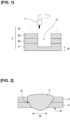
- a workpiece 2 which is made from a plurality of overlapping non-ferrous metal plates, has a machined hole 21 formed in advance at a welding site.
- the machined hole is a non-through-hole that penetrates all of a non-ferrous metal plate 3 (hereinafter sometimes referred to as the "front plate”) that is disposed nearer an arc welder 1 than a non-ferrous metal plate 4 (hereinafter sometimes referred to as the "back plate”) that is farthest from the welder, the non-through-hole reaching the back plate 4 and being a recess in part of the back plate 4.
- a welding torch is rotated to cause arc radiation from an opening side of the machined hole 21 toward an inner peripheral surface of the machined hole 21, and the inner peripheral surface of the machined hole 21 is melted together with a wire.
- a bottom surface of the machined hole 21 melts, and when the melting reaches a back surface of the back plate 4, the arc radiation is stopped to allow solidification, whereby a plurality of overlapping non-ferrous metal plates are joined together.
- the number of front plates 3 is not limited to one; a plurality of front plates may overlap.
- a machined hole recessed into part of the back plate is formed, whereby the inner peripheral side surface of the machined hole is also formed in the back plate, and the back plate melts together with the front plate, which is adjacent in an in-plane direction of a joining interface. Therefore, the need for a backing tool is eliminated.
- the arc welding method of the present invention can be used to melt a workpiece made from overlapping non-ferrous metal plates in the in-plane direction of the joining interface without melting the workpiece in the thickness direction, and the vicinity of the joining interface can therefore be melted early and the back plate and the front plate can be joined before the bottom surface of the machined hole melts through.
- the workpiece As the workpiece is melted in the direction of the joining interface, the workpiece also melts in the thickness direction of the workpiece.
- the molten portion spreads sufficiently in the in-plane direction of the joining interface as shown in Fig. 2 , the machined hole is filled by the molten metal from the welding wire, and joining strength can be ensured by the molten part formed by these parts solidifying.
- Fig. 1 shows an embodiment in which arc radiation is caused from above the machined hole formed in the workpiece to perform welding, but it is also possible to rotate the workpiece 90° to cause the opening of the machined hole to face to the side, and to perform welding by causing arc radiation from the side.
- the welding energy inputted to the workpiece depends on a material and thickness of the non-ferrous metal plates as well as a depth and diameter of the machined hole, but it is preferable that the current is 50 to 350 A (amperes) and the energization time is 0.5 to 5 seconds.
- the molten metal will drop and separate from the joined portion, the molten part where the molten metal solidifies will decrease in volume, and joining strength will decrease.
- the recessed portion of the back plate (where the machined hole is formed) is preferably of a thickness that is greater than 1/20 of the diameter of the machined hole.
- Fig. 3 shows a relationship between the thickness of the back plate at the location where the machined hole is formed and cross tensile strength (CTS) when a 4 mm diameter machined hole is formed in a 5000 series aluminum alloy plate
- Fig. 4 shows the relationship between the thickness of the back plate at the location where the machined hole is formed and cross tensile strength (CTS) when an 8 mm diameter machined hole is formed.
- the back plate at the joining interface can be melted in the direction of the joining interface.
- the above-described machined hole is preferably cylindrical. Due to the inner peripheral surface of the machined hole formed in the front plate adjacent to the back plate being flush with the back plate, the back plate and the front plate can be melted simultaneously at the joining interface of the back plate and the front plate, and the plates therefore melt readily in the direction of the joining interface.
- the diameter of the above-described machined hole depends on the required joining strength, but is preferably greater than three times the thickness of the thinnest non-ferrous metal plate among the non-ferrous metal plates constituting the above-described workpiece. If the diameter of the above-described machined hole is smaller than three times the thickness of the thinnest non-ferrous metal plate among the non-ferrous metal plates constituting the above-described workpiece, the volume of the machined hole will be small, so even if the molten metal fills the machined hole, the amount of heat in the metal will be small. As a result, heat will be readily dissipated by the surrounding base material, the plates will not melt readily in the direction of the joining interface, and welding defects such as incomplete welds will occur.
- the weld strength is determined by the weld strength of the thinnest plate, and this weld strength correlates with the diameter of the drilled hole, as shown in Fig. 5 .
- the thickness of the thinnest plate member is 1 mm
- the required strength of the product is 2.0 kN
- a strength of 2.5 kN or greater can be guaranteed by making the diameter of the machined hole 4.5 mm or greater.
- the above-described arc welding method can be applied to the welding of non-ferrous metal plates, and examples of the metals constituting the non-ferrous metal plates include aluminum, magnesium, titanium, and alloys containing these metals.
- the weld strength of a joint is determined by a diameter of a joining interface 51 of two plate members in a molten part 5; therefore, in order to know the weld strength of the joint, it is necessary to measure the diameter of the joining interface 51 of the molten part 5. However, it is difficult to measure the diameter of the joining interface 51 of the molten part 4 from the outside.
- the machined hole 21 passing through the joining interface 51 is formed in the welded portion, and an edge of the joining interface 51 is exposed; therefore, the vicinity of the joining interface can be directly melted through the machined hole 21, and the vicinity of the joining interface can be melted without melting the bottom surface of machined hole 21. Therefore, if the molten part 5 is formed up to a back surface 41 of the back plate 4, the diameter of the molten part at the joining interface 51 will be greater than a diameter 52 of the molten part present on the back surface 41.
- the weld strength of a joint welded using the arc welding method of the present invention can be estimated from the diameter 52 of the molten part present on the back surface 41 of the back plate 4.
- Fig. 6 shows a relationship between the diameter of the molten part present on the back surface of the back plate and tensile shear strength in a joint welded using the arc welding method of the present invention.
- a method for inspecting the weld strength of the joint requires only measuring the diameter of the molten part present on the visible back surface of the back plate, and the weld strength of the joint can be easily estimated; therefore, it is possible to inspect all joints rather than merely conducting a sample inspection.
Landscapes
- Engineering & Computer Science (AREA)
- Mechanical Engineering (AREA)
- Physics & Mathematics (AREA)
- Plasma & Fusion (AREA)
- Quality & Reliability (AREA)
- Arc Welding In General (AREA)
- Analysing Materials By The Use Of Radiation (AREA)
- Butt Welding And Welding Of Specific Article (AREA)
Abstract
Description
- The present invention relates to an arc welding method and a method for inspecting weld strength of a joint welded using the arc welding method, and more specifically to an arc welding method for joining non-ferrous metal plates together and a method for inspecting weld strength of a joint welded using the arc welding method.
- There are known arc spot welding methods used when joining a plurality of plate materials by welding in which a machined hole is formed in a plate member on an arc-welder side of a workpiece made from overlapping plate members, and joining the plate members by wire-fed arc spot welding.
-
Patent Citation 1 indicates that when arc spot welding is performed by melting an inner wall of a machined hole formed in the above-mentioned plate member, a melt depth in a lower plate member increases and burn-through occurs, so a backing tool is butted against the lower plate member. - Patent Citation 1:
Japanese Laid-open Patent Application No. 06-039542 - However, in actual production sites, there may be limitations on workpiece shape or on a space on a back side of the workpiece, and it is often not possible to use a backing tool.
- The present invention was devised in consideration of such problems associated with the prior art, it being an object of the invention to provide an arc welding method that does not require a backing jig and enables arc spot welding even when there is limited space on the back side of the workpiece.
- As a result of earnest research intended to achieve the objective described above, the inventors discovered that the objective described above could be achieved by forming a machined hole not only in a plate member on an arc-welder side but also up to a plate member on a side farthest from the arc welder, thus perfecting the present invention.
- Specifically, in the arc welding method of the present invention, at least part of a workpiece made from a plurality of overlapping non-ferrous metal plates is melted and joined. The arc welding method of the present invention is characterized in that the workpiece has a machined hole in a welded portion, the machined hole is a non-through-hole that penetrates a non-ferrous metal plate on an arc-radiation side to reach a non-ferrous metal plate on a side farthest from an arc welder and that is a recess in part of the non-ferrous metal plate, arc radiation is caused from an opening side of the machined hole, and the workpiece is melted and welded up to a back surface of the non-ferrous metal plate on the farthest side without using a backing jig on an opposite side of the workpiece.
- In addition, in a weld strength inspection method of the present invention, a weld strength of a joint welded using the arc welding method is inspected.
The weld strength inspection method is characterized in that the weld strength is estimated from a diameter of a molten part present on the back surface of the non-ferrous metal plate on the farthest side. - According to the present invention, a machining hole is formed not only in a plate member on an arc-welder side but also up to a plate member on a side farthest from the arc welder; therefore, an arc welding method can be provided with which it is possible to weld without using a backing tool, and also to weld even when there is limited space on a back side of a workpiece.
-
-
Fig. 1 is a cross-sectional view of a main portion illustrating the arc welding method of the present invention; -
Fig. 2 is a cross-sectional view of a main portion of a joint welded using the arc welding method of the present invention; -
Fig. 3 is a graph of a relationship between plate thickness at a machined hole formation spot in a non-ferrous metal plate on a side farthest from an arc welder and whether or not burn-through occurs in a welded portion, when the machined hole is 4 mm in diameter; -
Fig. 4 is a graph of the relationship between plate thickness at the machined hole formation spot in the non-ferrous metal plate on the side farthest from the arc welder and whether or not burn-through occurs in the welded portion, when the machined hole is 8 mm in diameter; -
Fig. 5 is a graph of a relationship between machined hole diameter and strength of a molten part formed in a joint; and -
Fig. 6 is a graph of a relationship between tensile shear strength of a joint and a diameter of a molten part present on a back surface of a non-ferrous metal plate on a side farthest from an arc welder. - The arc welding method of the present invention shall be described in detail. The arc welding method of the present invention is a welding method in which at least a portion of a workpiece is melted by an arc and a plurality of overlapping non-ferrous metal plates are joined together.
- A
workpiece 2, which is made from a plurality of overlapping non-ferrous metal plates, has a machinedhole 21 formed in advance at a welding site. As shown inFig. 1 , the machined hole is a non-through-hole that penetrates all of a non-ferrous metal plate 3 (hereinafter sometimes referred to as the "front plate") that is disposed nearer anarc welder 1 than a non-ferrous metal plate 4 (hereinafter sometimes referred to as the "back plate") that is farthest from the welder, the non-through-hole reaching theback plate 4 and being a recess in part of theback plate 4. - A welding torch is rotated to cause arc radiation from an opening side of the
machined hole 21 toward an inner peripheral surface of themachined hole 21, and the inner peripheral surface of themachined hole 21 is melted together with a wire. As a result, a bottom surface of themachined hole 21 melts, and when the melting reaches a back surface of theback plate 4, the arc radiation is stopped to allow solidification, whereby a plurality of overlapping non-ferrous metal plates are joined together. The number offront plates 3 is not limited to one; a plurality of front plates may overlap. - In the arc welding method of the present invention, a machined hole recessed into part of the back plate is formed, whereby the inner peripheral side surface of the machined hole is also formed in the back plate, and the back plate melts together with the front plate, which is adjacent in an in-plane direction of a joining interface. Therefore, the need for a backing tool is eliminated.
- In other words, in cases where a back plate is simply joined to an adjacent front plate, regardless of joining strength, the joining interface needs to melt, and if the back plate is not recessed but flat, the back plate cannot melt in the direction of the joining interface unless the bottom of the machined hole melts. Therefore, in order to join a back plate to an adjacent front plate, the back plate needs to first melt in a thickness direction thereof. By contrast, if a portion of the back plate is recessed, the back plate can be melted immediately in the direction of the joining interface, and therefore the back plate can be joined to the adjacent front plate even if the bottom surface of the back plate does not melt.
- Thus, the arc welding method of the present invention can be used to melt a workpiece made from overlapping non-ferrous metal plates in the in-plane direction of the joining interface without melting the workpiece in the thickness direction, and the vicinity of the joining interface can therefore be melted early and the back plate and the front plate can be joined before the bottom surface of the machined hole melts through.
- As the workpiece is melted in the direction of the joining interface, the workpiece also melts in the thickness direction of the workpiece. By causing arc radiation until the back surface of the back plate melts, the molten portion spreads sufficiently in the in-plane direction of the joining interface as shown in
Fig. 2 , the machined hole is filled by the molten metal from the welding wire, and joining strength can be ensured by the molten part formed by these parts solidifying. - In addition, since the vicinity of the joining interface can be melted early, welding energy delivered to the workpiece is reduced, and not only can deformation of the workpiece be minimized, but the amount of fumes and dust generated can also be minimized.
-
Fig. 1 shows an embodiment in which arc radiation is caused from above the machined hole formed in the workpiece to perform welding, but it is also possible to rotate the workpiece 90° to cause the opening of the machined hole to face to the side, and to perform welding by causing arc radiation from the side. - The welding energy inputted to the workpiece depends on a material and thickness of the non-ferrous metal plates as well as a depth and diameter of the machined hole, but it is preferable that the current is 50 to 350 A (amperes) and the energization time is 0.5 to 5 seconds.
- If too much welding energy is inputted to the workpiece, the molten metal will drop and separate from the joined portion, the molten part where the molten metal solidifies will decrease in volume, and joining strength will decrease.
- The recessed portion of the back plate (where the machined hole is formed) is preferably of a thickness that is greater than 1/20 of the diameter of the machined hole.
-
Fig. 3 shows a relationship between the thickness of the back plate at the location where the machined hole is formed and cross tensile strength (CTS) when a 4 mm diameter machined hole is formed in a 5000 series aluminum alloy plate, andFig. 4 shows the relationship between the thickness of the back plate at the location where the machined hole is formed and cross tensile strength (CTS) when an 8 mm diameter machined hole is formed. - It can be seen from
Figs. 3 and 4 that by making the thickness of the recessed portion of the back plate greater than 1/20 of the diameter of the machined hole, burn-through of the molten metal is prevented and the volume of the molten part is prevented from decreasing. - Furthermore, if the recess formed in the back plate is 0.1 mm or more in depth, the back plate at the joining interface can be melted in the direction of the joining interface.
- The above-described machined hole is preferably cylindrical. Due to the inner peripheral surface of the machined hole formed in the front plate adjacent to the back plate being flush with the back plate, the back plate and the front plate can be melted simultaneously at the joining interface of the back plate and the front plate, and the plates therefore melt readily in the direction of the joining interface.
- The diameter of the above-described machined hole depends on the required joining strength, but is preferably greater than three times the thickness of the thinnest non-ferrous metal plate among the non-ferrous metal plates constituting the above-described workpiece. If the diameter of the above-described machined hole is smaller than three times the thickness of the thinnest non-ferrous metal plate among the non-ferrous metal plates constituting the above-described workpiece, the volume of the machined hole will be small, so even if the molten metal fills the machined hole, the amount of heat in the metal will be small. As a result, heat will be readily dissipated by the surrounding base material, the plates will not melt readily in the direction of the joining interface, and welding defects such as incomplete welds will occur.
- When a plurality of plates are overlapped and welded together, the weld strength is determined by the weld strength of the thinnest plate, and this weld strength correlates with the diameter of the drilled hole, as shown in
Fig. 5 . - For example, when the thickness of the thinnest plate member is 1 mm, if the required strength of the product is 2.0 kN, a strength of 2.5 kN or greater can be guaranteed by making the diameter of the machined hole 4.5 mm or greater.
- The above-described arc welding method can be applied to the welding of non-ferrous metal plates, and examples of the metals constituting the non-ferrous metal plates include aluminum, magnesium, titanium, and alloys containing these metals.
- A method for inspecting the weld strength of a joint welded using the above-described arc welding method of the present invention shall now be described.
- Generally, the weld strength of a joint is determined by a diameter of a
joining interface 51 of two plate members in amolten part 5; therefore, in order to know the weld strength of the joint, it is necessary to measure the diameter of thejoining interface 51 of themolten part 5. However, it is difficult to measure the diameter of the joininginterface 51 of themolten part 4 from the outside. - In the arc welding method of the present invention, as described above, the
machined hole 21 passing through thejoining interface 51 is formed in the welded portion, and an edge of thejoining interface 51 is exposed; therefore, the vicinity of the joining interface can be directly melted through themachined hole 21, and the vicinity of the joining interface can be melted without melting the bottom surface ofmachined hole 21. Therefore, if themolten part 5 is formed up to aback surface 41 of theback plate 4, the diameter of the molten part at the joininginterface 51 will be greater than adiameter 52 of the molten part present on theback surface 41. - Therefore, the weld strength of a joint welded using the arc welding method of the present invention can be estimated from the
diameter 52 of the molten part present on theback surface 41 of theback plate 4. -
Fig. 6 shows a relationship between the diameter of the molten part present on the back surface of the back plate and tensile shear strength in a joint welded using the arc welding method of the present invention. - It can be seen from
Fig. 6 that there is a correlation between the tensile strength of the joint and the diameter of the molten part present on the back surface of the back plate, and for a joint welded using the arc welding method of the present invention, it is possible to estimate the weld strength of the joint by measuring the diameter of the molten part present on the back surface of the back plate. - Thus, a method for inspecting the weld strength of the joint requires only measuring the diameter of the molten part present on the visible back surface of the back plate, and the weld strength of the joint can be easily estimated; therefore, it is possible to inspect all joints rather than merely conducting a sample inspection.
-
- 1
- Arc welder
- 2
- Workpiece
- 21
- Machined hole
- 22
- Thickness of back plate at machined hole formation spot
- 3
- Non-ferrous metal plate (front plate) on arc-welder side
- 4
- Non-ferrous metal plate (back plate) on side farthest from arc welder
- 41
- Back surface
- 5
- Molten part
- 51
- Joining interface
- 52
- Diameter of molten part present on back surface
Claims (5)
- An arc welding method for melting and joining at least a part of a workpiece having a plurality of overlapping non-ferrous metal plates, the arc welding method comprising:forming a machined hole in a welded portion of the workpiece,wherein the machined hole is a non-through-hole that penetrates a non-ferrous metal plate on an arc-radiation side, and reaches a non-ferrous metal plate on a side farthest from an arc welder to form a partial recess portion; andcausing arc radiation from an opening side of the machined hole to melt and weld a back surface of the non-ferrous metal plate furthest from the workpiece without using a backing jig on an opposite side of the workpiece.
- The arc welding method according to claim 1, wherein the machined hole is cylindrical.
- The arc welding method according to claim 2, wherein the recess portion of the non-ferrous metal plate on the farthest side has a plate thickness greater than 1/20 of a diameter of the machined hole.
- The arc welding method according to claim 3, wherein the diameter of the machined hole is greater than three times a thickness of a thinnest non-ferrous metal plate among the non-ferrous metal plates forming the workpiece.
- A method for inspecting a weld strength of the joint welded using the arc welding method according to any one of claims 1 to 4, the weld strength inspection method comprising estimating the weld strength from a diameter of a molten part present on a back surface of the non-ferrous metal plate on the farthest side.
Applications Claiming Priority (1)
| Application Number | Priority Date | Filing Date | Title |
|---|---|---|---|
| PCT/JP2022/025596 WO2024003992A1 (en) | 2022-06-27 | 2022-06-27 | Arc welding method, and method for inspecting welding strength of joined article welded through said arc welding method |
Publications (1)
| Publication Number | Publication Date |
|---|---|
| EP4545234A1 true EP4545234A1 (en) | 2025-04-30 |
Family
ID=89381794
Family Applications (1)
| Application Number | Title | Priority Date | Filing Date |
|---|---|---|---|
| EP22949271.5A Withdrawn EP4545234A1 (en) | 2022-06-27 | 2022-06-27 | Arc welding method, and method for inspecting welding strength of joined article welded through said arc welding method |
Country Status (5)
| Country | Link |
|---|---|
| US (1) | US12465990B2 (en) |
| EP (1) | EP4545234A1 (en) |
| JP (1) | JP7678413B2 (en) |
| CN (1) | CN119403638B (en) |
| WO (1) | WO2024003992A1 (en) |
Family Cites Families (8)
| Publication number | Priority date | Publication date | Assignee | Title |
|---|---|---|---|---|
| JPH0639542A (en) * | 1992-07-24 | 1994-02-15 | Sekisui Chem Co Ltd | Arc spot welding method |
| JP5842734B2 (en) * | 2011-05-27 | 2016-01-13 | 新日鐵住金株式会社 | Arc spot welded joint with excellent joint strength and manufacturing method thereof |
| JP6285724B2 (en) * | 2014-01-14 | 2018-02-28 | 株式会社アマダミヤチ | Joining method and joining apparatus |
| EP3498410A4 (en) * | 2016-08-09 | 2019-08-21 | Panasonic Intellectual Property Management Co., Ltd. | JUNCTION STRUCTURE |
| CN113692328B (en) * | 2019-04-19 | 2023-05-05 | 松下知识产权经营株式会社 | Joint structure |
| EP3957426A4 (en) * | 2019-04-19 | 2022-06-15 | Panasonic Intellectual Property Management Co., Ltd. | Joining structure |
| JP6999015B2 (en) * | 2020-12-07 | 2022-01-18 | 株式会社神戸製鋼所 | Arc welding method for joining dissimilar materials |
| JP7593900B2 (en) * | 2021-08-23 | 2024-12-03 | 株式会社神戸製鋼所 | Arc spot welding method for joining dissimilar materials |
-
2022
- 2022-06-27 WO PCT/JP2022/025596 patent/WO2024003992A1/en not_active Ceased
- 2022-06-27 JP JP2024530095A patent/JP7678413B2/en active Active
- 2022-06-27 US US18/865,806 patent/US12465990B2/en active Active
- 2022-06-27 EP EP22949271.5A patent/EP4545234A1/en not_active Withdrawn
- 2022-06-27 CN CN202280097299.XA patent/CN119403638B/en active Active
Also Published As
| Publication number | Publication date |
|---|---|
| US20250256343A1 (en) | 2025-08-14 |
| CN119403638B (en) | 2025-10-17 |
| CN119403638A (en) | 2025-02-07 |
| JPWO2024003992A1 (en) | 2024-01-04 |
| JP7678413B2 (en) | 2025-05-16 |
| WO2024003992A1 (en) | 2024-01-04 |
| US12465990B2 (en) | 2025-11-11 |
Similar Documents
| Publication | Publication Date | Title |
|---|---|---|
| CN111801189B (en) | Arc welding method for joining dissimilar materials | |
| US9937587B2 (en) | Process for friction stir welding dissimilar metals and workpiece assemblies formed thereby | |
| CN109641307B (en) | Arc spot welding method for joining dissimilar materials, auxiliary parts for joining, and welded joints for dissimilar materials | |
| EP3868506A1 (en) | Welding method for bonding dissimilar materials, bonding auxiliary member, and dissimilar material welded joint | |
| EP3517243A1 (en) | Spot welding method for joining different materials, joining assistance member, and different material welded joint | |
| JP7347235B2 (en) | Liquid cooling jacket manufacturing method and friction stir welding method | |
| CN103080384B (en) | Electrochemical anode with friction stir welded joint and method of making same | |
| WO2023032740A1 (en) | Battery case and method for manufacturing battery case | |
| US20050116012A1 (en) | Method for metal and alloy joining using bulk friction stir welding | |
| JP3617585B2 (en) | Method of lining titanium or titanium alloy material to steel | |
| US12465990B2 (en) | Arc welding method, and method for inspecting welding strength of joint welded using arc welding method | |
| JP6999015B2 (en) | Arc welding method for joining dissimilar materials | |
| EP3517240A1 (en) | Arc welding method for joining different materials, joining assistance member, and different material welded joint | |
| Yusof et al. | Ultra-thin Friction Stir Welding (FSW) between aluminum alloy and copper | |
| EP3957426A1 (en) | Joining structure | |
| WO2021210322A1 (en) | Arc spot welding method for joining dissimilar materials | |
| JP2024177867A (en) | Inspection method for dissimilar metal joints, inspection device for dissimilar metal joints, welding method, and welding system | |
| KR20240033280A (en) | Heat-assisted self-piercing riveting for high-strength 7XXX aluminum | |
| Anganan et al. | Study of mechanical properties and experimental comparison of Mig and Friction stir welding processes for aa6082-t6 aluminium alloy | |
| Wojdat et al. | Microstructure and mechanical properties of braze welded joints of copper with austenitic steel made by CMT method | |
| JP2007296573A (en) | Stud welding method | |
| JP2024180068A (en) | Dissimilar metal joints | |
| JPH09295168A (en) | Electroslag welding method | |
| WO2025164641A1 (en) | Joining structure | |
| Myśliwiec et al. | Możliwości łączenia cienkich blach ze stopów Al, Mg oraz tytanu GRADE 3 w procesie FSW |
Legal Events
| Date | Code | Title | Description |
|---|---|---|---|
| STAA | Information on the status of an ep patent application or granted ep patent |
Free format text: STATUS: THE INTERNATIONAL PUBLICATION HAS BEEN MADE |
|
| PUAI | Public reference made under article 153(3) epc to a published international application that has entered the european phase |
Free format text: ORIGINAL CODE: 0009012 |
|
| STAA | Information on the status of an ep patent application or granted ep patent |
Free format text: STATUS: REQUEST FOR EXAMINATION WAS MADE |
|
| STAA | Information on the status of an ep patent application or granted ep patent |
Free format text: STATUS: THE APPLICATION HAS BEEN WITHDRAWN |
|
| 17P | Request for examination filed |
Effective date: 20250122 |
|
| AK | Designated contracting states |
Kind code of ref document: A1 Designated state(s): AL AT BE BG CH CY CZ DE DK EE ES FI FR GB GR HR HU IE IS IT LI LT LU LV MC MK MT NL NO PL PT RO RS SE SI SK SM TR |
|
| 18W | Application withdrawn |
Effective date: 20250407 |