EP4545189A1 - A method and coater for coating of a flat substrate - Google Patents
A method and coater for coating of a flat substrate Download PDFInfo
- Publication number
- EP4545189A1 EP4545189A1 EP23206362.8A EP23206362A EP4545189A1 EP 4545189 A1 EP4545189 A1 EP 4545189A1 EP 23206362 A EP23206362 A EP 23206362A EP 4545189 A1 EP4545189 A1 EP 4545189A1
- Authority
- EP
- European Patent Office
- Prior art keywords
- flat substrate
- application roller
- roller
- print job
- coater
- Prior art date
- Legal status (The legal status is an assumption and is not a legal conclusion. Google has not performed a legal analysis and makes no representation as to the accuracy of the status listed.)
- Pending
Links
Images

Classifications
-
- B—PERFORMING OPERATIONS; TRANSPORTING
- B41—PRINTING; LINING MACHINES; TYPEWRITERS; STAMPS
- B41J—TYPEWRITERS; SELECTIVE PRINTING MECHANISMS, i.e. MECHANISMS PRINTING OTHERWISE THAN FROM A FORME; CORRECTION OF TYPOGRAPHICAL ERRORS
- B41J11/00—Devices or arrangements of selective printing mechanisms, e.g. ink-jet printers or thermal printers, for supporting or handling copy material in sheet or web form
- B41J11/0015—Devices or arrangements of selective printing mechanisms, e.g. ink-jet printers or thermal printers, for supporting or handling copy material in sheet or web form for treating before, during or after printing or for uniform coating or laminating the copy material before or after printing
-
- B—PERFORMING OPERATIONS; TRANSPORTING
- B05—SPRAYING OR ATOMISING IN GENERAL; APPLYING FLUENT MATERIALS TO SURFACES, IN GENERAL
- B05C—APPARATUS FOR APPLYING FLUENT MATERIALS TO SURFACES, IN GENERAL
- B05C1/00—Apparatus in which liquid or other fluent material is applied to the surface of the work by contact with a member carrying the liquid or other fluent material, e.g. a porous member loaded with a liquid to be applied as a coating
- B05C1/04—Apparatus in which liquid or other fluent material is applied to the surface of the work by contact with a member carrying the liquid or other fluent material, e.g. a porous member loaded with a liquid to be applied as a coating for applying liquid or other fluent material to work of indefinite length
- B05C1/08—Apparatus in which liquid or other fluent material is applied to the surface of the work by contact with a member carrying the liquid or other fluent material, e.g. a porous member loaded with a liquid to be applied as a coating for applying liquid or other fluent material to work of indefinite length using a roller or other rotating member which contacts the work along a generating line
- B05C1/0873—Controlling means responsive to conditions of the liquid or other fluent material, of the ambient medium, of the roller or of the work
-
- B—PERFORMING OPERATIONS; TRANSPORTING
- B05—SPRAYING OR ATOMISING IN GENERAL; APPLYING FLUENT MATERIALS TO SURFACES, IN GENERAL
- B05C—APPARATUS FOR APPLYING FLUENT MATERIALS TO SURFACES, IN GENERAL
- B05C1/00—Apparatus in which liquid or other fluent material is applied to the surface of the work by contact with a member carrying the liquid or other fluent material, e.g. a porous member loaded with a liquid to be applied as a coating
- B05C1/04—Apparatus in which liquid or other fluent material is applied to the surface of the work by contact with a member carrying the liquid or other fluent material, e.g. a porous member loaded with a liquid to be applied as a coating for applying liquid or other fluent material to work of indefinite length
- B05C1/08—Apparatus in which liquid or other fluent material is applied to the surface of the work by contact with a member carrying the liquid or other fluent material, e.g. a porous member loaded with a liquid to be applied as a coating for applying liquid or other fluent material to work of indefinite length using a roller or other rotating member which contacts the work along a generating line
- B05C1/0808—Details thereof, e.g. surface characteristics
-
- B—PERFORMING OPERATIONS; TRANSPORTING
- B05—SPRAYING OR ATOMISING IN GENERAL; APPLYING FLUENT MATERIALS TO SURFACES, IN GENERAL
- B05C—APPARATUS FOR APPLYING FLUENT MATERIALS TO SURFACES, IN GENERAL
- B05C1/00—Apparatus in which liquid or other fluent material is applied to the surface of the work by contact with a member carrying the liquid or other fluent material, e.g. a porous member loaded with a liquid to be applied as a coating
- B05C1/04—Apparatus in which liquid or other fluent material is applied to the surface of the work by contact with a member carrying the liquid or other fluent material, e.g. a porous member loaded with a liquid to be applied as a coating for applying liquid or other fluent material to work of indefinite length
- B05C1/08—Apparatus in which liquid or other fluent material is applied to the surface of the work by contact with a member carrying the liquid or other fluent material, e.g. a porous member loaded with a liquid to be applied as a coating for applying liquid or other fluent material to work of indefinite length using a roller or other rotating member which contacts the work along a generating line
- B05C1/0826—Apparatus in which liquid or other fluent material is applied to the surface of the work by contact with a member carrying the liquid or other fluent material, e.g. a porous member loaded with a liquid to be applied as a coating for applying liquid or other fluent material to work of indefinite length using a roller or other rotating member which contacts the work along a generating line the work being a web or sheets
- B05C1/083—Apparatus in which liquid or other fluent material is applied to the surface of the work by contact with a member carrying the liquid or other fluent material, e.g. a porous member loaded with a liquid to be applied as a coating for applying liquid or other fluent material to work of indefinite length using a roller or other rotating member which contacts the work along a generating line the work being a web or sheets being passed between the coating roller and one or more backing rollers
-
- B—PERFORMING OPERATIONS; TRANSPORTING
- B05—SPRAYING OR ATOMISING IN GENERAL; APPLYING FLUENT MATERIALS TO SURFACES, IN GENERAL
- B05C—APPARATUS FOR APPLYING FLUENT MATERIALS TO SURFACES, IN GENERAL
- B05C1/00—Apparatus in which liquid or other fluent material is applied to the surface of the work by contact with a member carrying the liquid or other fluent material, e.g. a porous member loaded with a liquid to be applied as a coating
- B05C1/04—Apparatus in which liquid or other fluent material is applied to the surface of the work by contact with a member carrying the liquid or other fluent material, e.g. a porous member loaded with a liquid to be applied as a coating for applying liquid or other fluent material to work of indefinite length
- B05C1/08—Apparatus in which liquid or other fluent material is applied to the surface of the work by contact with a member carrying the liquid or other fluent material, e.g. a porous member loaded with a liquid to be applied as a coating for applying liquid or other fluent material to work of indefinite length using a roller or other rotating member which contacts the work along a generating line
- B05C1/0826—Apparatus in which liquid or other fluent material is applied to the surface of the work by contact with a member carrying the liquid or other fluent material, e.g. a porous member loaded with a liquid to be applied as a coating for applying liquid or other fluent material to work of indefinite length using a roller or other rotating member which contacts the work along a generating line the work being a web or sheets
- B05C1/0834—Apparatus in which liquid or other fluent material is applied to the surface of the work by contact with a member carrying the liquid or other fluent material, e.g. a porous member loaded with a liquid to be applied as a coating for applying liquid or other fluent material to work of indefinite length using a roller or other rotating member which contacts the work along a generating line the work being a web or sheets the coating roller co-operating with other rollers, e.g. dosing, transfer rollers
-
- B—PERFORMING OPERATIONS; TRANSPORTING
- B05—SPRAYING OR ATOMISING IN GENERAL; APPLYING FLUENT MATERIALS TO SURFACES, IN GENERAL
- B05C—APPARATUS FOR APPLYING FLUENT MATERIALS TO SURFACES, IN GENERAL
- B05C1/00—Apparatus in which liquid or other fluent material is applied to the surface of the work by contact with a member carrying the liquid or other fluent material, e.g. a porous member loaded with a liquid to be applied as a coating
- B05C1/04—Apparatus in which liquid or other fluent material is applied to the surface of the work by contact with a member carrying the liquid or other fluent material, e.g. a porous member loaded with a liquid to be applied as a coating for applying liquid or other fluent material to work of indefinite length
- B05C1/08—Apparatus in which liquid or other fluent material is applied to the surface of the work by contact with a member carrying the liquid or other fluent material, e.g. a porous member loaded with a liquid to be applied as a coating for applying liquid or other fluent material to work of indefinite length using a roller or other rotating member which contacts the work along a generating line
- B05C1/0873—Controlling means responsive to conditions of the liquid or other fluent material, of the ambient medium, of the roller or of the work
- B05C1/0886—Controlling means responsive to conditions of the liquid or other fluent material, of the ambient medium, of the roller or of the work responsive to the condition of the work
-
- B—PERFORMING OPERATIONS; TRANSPORTING
- B05—SPRAYING OR ATOMISING IN GENERAL; APPLYING FLUENT MATERIALS TO SURFACES, IN GENERAL
- B05C—APPARATUS FOR APPLYING FLUENT MATERIALS TO SURFACES, IN GENERAL
- B05C1/00—Apparatus in which liquid or other fluent material is applied to the surface of the work by contact with a member carrying the liquid or other fluent material, e.g. a porous member loaded with a liquid to be applied as a coating
- B05C1/04—Apparatus in which liquid or other fluent material is applied to the surface of the work by contact with a member carrying the liquid or other fluent material, e.g. a porous member loaded with a liquid to be applied as a coating for applying liquid or other fluent material to work of indefinite length
- B05C1/08—Apparatus in which liquid or other fluent material is applied to the surface of the work by contact with a member carrying the liquid or other fluent material, e.g. a porous member loaded with a liquid to be applied as a coating for applying liquid or other fluent material to work of indefinite length using a roller or other rotating member which contacts the work along a generating line
- B05C1/12—Apparatus in which liquid or other fluent material is applied to the surface of the work by contact with a member carrying the liquid or other fluent material, e.g. a porous member loaded with a liquid to be applied as a coating for applying liquid or other fluent material to work of indefinite length using a roller or other rotating member which contacts the work along a generating line the work being fed round the roller
-
- B—PERFORMING OPERATIONS; TRANSPORTING
- B05—SPRAYING OR ATOMISING IN GENERAL; APPLYING FLUENT MATERIALS TO SURFACES, IN GENERAL
- B05C—APPARATUS FOR APPLYING FLUENT MATERIALS TO SURFACES, IN GENERAL
- B05C5/00—Apparatus in which liquid or other fluent material is projected, poured or allowed to flow on to the surface of the work
- B05C5/005—Curtain coaters
-
- B—PERFORMING OPERATIONS; TRANSPORTING
- B05—SPRAYING OR ATOMISING IN GENERAL; APPLYING FLUENT MATERIALS TO SURFACES, IN GENERAL
- B05D—PROCESSES FOR APPLYING FLUENT MATERIALS TO SURFACES, IN GENERAL
- B05D1/00—Processes for applying liquids or other fluent materials
- B05D1/28—Processes for applying liquids or other fluent materials performed by transfer from the surfaces of elements carrying the liquid or other fluent material, e.g. brushes, pads, rollers
-
- B—PERFORMING OPERATIONS; TRANSPORTING
- B41—PRINTING; LINING MACHINES; TYPEWRITERS; STAMPS
- B41F—PRINTING MACHINES OR PRESSES
- B41F23/00—Devices for treating the surfaces of sheets, webs, or other articles in connection with printing
- B41F23/08—Print finishing devices, e.g. for glossing prints
-
- B—PERFORMING OPERATIONS; TRANSPORTING
- B41—PRINTING; LINING MACHINES; TYPEWRITERS; STAMPS
- B41J—TYPEWRITERS; SELECTIVE PRINTING MECHANISMS, i.e. MECHANISMS PRINTING OTHERWISE THAN FROM A FORME; CORRECTION OF TYPOGRAPHICAL ERRORS
- B41J11/00—Devices or arrangements of selective printing mechanisms, e.g. ink-jet printers or thermal printers, for supporting or handling copy material in sheet or web form
- B41J11/0095—Detecting means for copy material, e.g. for detecting or sensing presence of copy material or its leading or trailing end
-
- B—PERFORMING OPERATIONS; TRANSPORTING
- B41—PRINTING; LINING MACHINES; TYPEWRITERS; STAMPS
- B41J—TYPEWRITERS; SELECTIVE PRINTING MECHANISMS, i.e. MECHANISMS PRINTING OTHERWISE THAN FROM A FORME; CORRECTION OF TYPOGRAPHICAL ERRORS
- B41J2/00—Typewriters or selective printing mechanisms characterised by the printing or marking process for which they are designed
- B41J2/005—Typewriters or selective printing mechanisms characterised by the printing or marking process for which they are designed characterised by bringing liquid or particles selectively into contact with a printing material
- B41J2/01—Ink jet
- B41J2/135—Nozzles
- B41J2/145—Arrangement thereof
- B41J2/155—Arrangement thereof for line printing
Definitions
- the present invention relates to a method for coating a flat substrate by a coater comprising an entry station for receiving the flat substrate to be coated, a control system for controlling print job data, print job settings and coater settings, an application module comprising a supporting roller for supporting the flat substrate and an application roller for transferring a layer of coating from a surface of the application roller towards the flat substrate, and an end station for storing the flat substrate when coated.
- Roll coating is a method of applying thin films of finishing material to flat substrate of wood, metal, carton, heavy-weight paper or plastic.
- the flat substrate may be a printed media.
- the principle of roll coating is well known and based on the physics of transferring a layer of coating from the surface of a roller to the surface of a substrate.
- Roll coating is a highly effective method, precise in application and environmentally friendly and offering nearly 100 % of transfer efficiency.
- the most common type of roll coater is the differential direct style where the moving components are individually and manually adjusted in speed and direction. In this way an operator controls the coating process.
- the process of transporting a layer of coating from the roll requires several key components.
- a conveyor belt or rolling system moves the substrate under the application roller to enable the film transfer.
- the application roller carries the coating film which will be transferred to the substrate.
- the application roller is covered with various materials and densities to facilitate the coating application.
- the application roller is exchangeable since, in the case that coating is done by means of substrates with knock out areas (places where no coating is wanted), each substrate length has its corresponding application roller diameter.
- the coater comprises an applying mechanism which is configured to apply the coating to the application roller.
- a known application mechanism comprises a metal doctor roller or metering roller which works in conjunction with the application roller to form a packet of coating called a nip.
- the film thickness on the application roller may be determined by the distance between the two rollers and the speed and rotation direction of each roller.
- the film thickness may also be determined by a mechanism which transfers the coating from a bulk storage to the application roller, for example by means of an anilox roller.
- Machine set up begins with an initial manual adjustment of the application roller to a desired height.
- the application roller is set to a light impression with respect to the substrate.
- Conveyor and application roll speed are set and synchronized based upon production requirements.
- the coated substrate is transferred to the end station.
- the weight of the coating film may be determined by a scale. From the resulting weight coating adjustments can be determined.
- the control system may also be referred to as controller or as control unit hereinafter.
- a method for coating the flat substrate wherein the coater comprises a first sensor for determining a radius of the application roller and the application module is configured to transport the flat substrate from the entry station in-between the supporting roller and the application roller towards the end station, wherein the method comprises the steps of a) the control system receiving print job data and print job settings, b) the control system determining a suitable impression of the application roller by means of received print job settings, c) the first sensor determining a radius of the application roller, d) determining an axis location of the application roller having a distance of the radius of the application roller plus a nominal thickness of the flat substrate read from the print job data minus the determined suitable impression from the supporting roller surface, e) automatically moving the application roller to the determined axis location, and f) starting the transport of the flat substrate from the entry station in-between the supporting roller and the application roller towards the end station.
- the first sensor is in place in order to errorlessly, accurately and instantaneously measure the radius of the application roller.
- the step of the control system determining a suitable impression of the application roller by means of the print job settings comprises the sub-steps of reading from the print job settings a type of the flat substrate, reading a hardness range for the type of flat substrate from a set of hardness ranges for types of media stored in memory of the control system, and deriving from the read hardness range a suitable impression of the application roller.
- the application module comprises a second sensor for determining an actual thickness of the flat substrate and the method comprises the steps of determining an actual thickness of the flat substrate and adjusting the determined axis location of the application roller and automatically moving the application roller to the adjusted axis location.
- the second sensor is positioned between the entry station and the application module or between the application module and the end station.
- the second sensor is positioned between the entry station and the application module.
- the flat substrate is a print medium which is printed upon by a printer connected to the coater.
- the printer proceeds the coater in a production process of printing upon a print medium which is after printing coated by the coater in order to deliver a coated and printed print medium.
- the printed print medium may also be called a printed medium.
- the present invention also relates to a coater comprising an entry station for entering a flat substrate to be coated, a control system for controlling print job data, print job settings and coater settings, an application module comprising a supporting roller for supporting the flat substrate and an application roller for transferring a layer of coating from a surface of the application roller towards the flat substrate, an end station for storing the flat substrate when coated, and a first sensor for determining a radius of the application roller, wherein the application module is configured to transport the flat substrate from the entry station in-between the supporting roller and the application roller towards the end station, and the coater is configured to perform the steps of the method according to the present invention.
- the coater is provided with a moving mechanism in order to move the application roller in a height direction.
- the application module comprises a second sensor for determining an actual thickness of the flat substrate, and the coater is configured to determine an actual thickness of the flat substrate and to adjust the determined axis location of the application roller and to automatically move the application roller to the adjusted axis location.
- the present invention further relates to a software product comprising program code on a machine-readable medium, which program code, when loaded into a control system of a coater, causes the coater to execute the steps of the method according to the present invention.
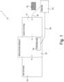
- Fig. 1 is a schematic drawing of a coater 1 configured to coat flat substrates 10 according to the present invention.
- the coater 1 comprises an entry station 11 for receiving 19 the flat substrate 10 to be coated, a control system 14 for controlling print job data, print job settings and coater settings, an application module 12 for transferring a layer of coating towards the flat substrate 10, and an end station 13 for storing the flat substrate 10 when coated.
- the control system 14 is configured to receive print job data and print job settings from a printer, i.e. from a print controller comprised in a printing system 15 which is wired 16 or wireless connected to the coater 1.
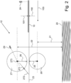
- Fig. 2 is a schematic drawing of the application module 12 comprised in the coater 1 according to the present invention.
- the application module 12 comprises a supporting roller 26 having a first radius 25.
- the supporting roller 26 supports the flat substrate 10 when moving over the support roller 10 by means of a conveyor belt 23.
- the application module 12 also comprises an application roller 27 for transferring a layer of coating from a surface of the application roller 27 towards the flat substrate 10.
- a first sensor 29 is positioned in the application module 12 in order to determine a radius 28 of the application roller 27.
- the application module is configured to transport the flat substrate 10 moving in a direction 103 from the entry station 11 (See Fig. 1 ) in-between the supporting roller 26 and the application roller 27 towards the end station 13 (See Fig. 1 ).
- the applying mechanism for applying the coating on the application roller 27 is not shown in Fig. 2 and not described hereinafter, since such applying mechanisms are known and not relevant for the present invention.
- the control system 14 is configured to determine a suitable impression of the application roller 27 by means of received print job settings.
- the first sensor 29 is configured to determine a radius 28 of the application roller 27 as a distance R 0 from a blanket surface of the application roller 27 to the core 273 of the application roller 27.
- the print job settings comprise a type of the flat substrate 10.
- the control system 14 is configured to read a hardness range for the type of flat substrate 10 from a set of hardness ranges for types of media stored in memory of the control system 14.
- the control system 14 is also configured to derive from the read hardness range a suitable impression x i of the application roller 27. In Fig. 2 the impression x i of the application roller 27 is indicated by the arrows 271, 272.
- a hardness ranges may be expressed in so-called Shore A hardness range, for example 25-35, 35-60 or 60-80.
- the Shore A hardness scale ranges from 0 to 100. Harder materials have higher Shore A values than softer materials. In practice the value for the impression x i depends on the hardness range of the substrate and may be for example approximately one millimeter.
- the heights 21 and 22 having respective values H 1 and H 0 are measured with respect to a zero plane 20 which may be for example the floor on which the coater is placed, a transportation belt on which the flat substrates arrive or a supporting structure of the transportation belt.
- the control system 14 of the coater 1 is configured to send instructions to a motor system (not shown) of the coater 1 in order to automatically move the axis 273 of the application roller 27 to the determined axis location.
- the transport of the flat substrate 10 from the entry station 11 in-between the supporting roller 26 and the application roller 27 towards the end station 13 can start.
- the application module 12 comprises a second sensor 24 for determining an actual thickness t 1 of the flat substrate 10 - indicated by the arrows 101, 102.
- the adjustment of D or H 0 may take place for every substrate in order to keep the impression for each substrate on a good level. Adjustment of D or H 0 takes place at a predetermined time after measuring the actual thickness t 1 by the sensor 24 and before the arrival of the substrate 10 in-between the supporting roller 25 and the application roller 27.
- the predetermined time depends on the horizontal distance between the second sensor 24 and the axis of the supporting roller 26 (which equals the horizontal distance between the second sensor 24 and the axis of the application roller 27), a speed of the conveyor belt 23 and a time period needed to move the application roller 27 to the redetermined axis location 273 of the application roller 27.
- the control system 14 is configured to adjust the determined axis location 273 of the application roller 27 and to instruct the motor system (not shown) to move the application roller 27 to the adjusted axis location 273.
- the move of the application roller 27 is planned in-between the flat substrates lying on the conveyor belt 23. Nevertheless a move of the application roller 27 may overlap with an end of the previous flat substrate in-between the supporting roller 26 and the application roller 27.
- the second sensor 24 in Fig. 2 is positioned between the entry station 11 and the application module 12. Nevertheless a position of the second sensor may be envisioned between the application module 12 and the end station 13.
- the flat substrate 10 may be a print medium which is printed upon by the printer 15 or by another printer as long as the printer is digitally connected to the coater 1 for transferring print job data and print job settings.
- the printer 15 may also physically connected to the coater 1 by placing the printer 15 in-line with the coater 1 in order to establish a smooth transport of the printed flat substrate 10 from the printer 15 to the entry station 11 of the coater 1.
- control unit 14 comprises a Central Processing Unit (CPU) 31, a Random Access Memory (RAM) 33, a Read Only Memory (ROM) 34, a network unit 36, an interface unit 37 and a hard disk (HD) 35.
- CPU Central Processing Unit
- RAM Random Access Memory
- ROM Read Only Memory
- network unit 36 an interface unit 37
- HD hard disk
- the aforementioned units 31 - 37 are interconnected through a bus system 38.
- the control unit 14 may also be a distributed control unit.
- the CPU 31 controls the coater 1 in accordance with control programs stored in the ROM 34 or on the HD 35 and the local user interface panel 11.
- a user interface may be envisioned that is installed close to and digitally connected to the coater, for example a user interface which is integrated with the user interface of a printing system from which the print jobs are received.
- the ROM 34 stores programs and data such as boot program, set-up program, various set-up data or the like, which are to be read out and executed by the CPU 31.
- the hard disk 35 is an example of a non-volatile storage unit for storing and saving programs and data which make the CPU 31 execute a coating process to be described later in the method according to the present invention.
- the hard disk 35 also comprises an area for saving the data of externally submitted print jobs, like print job settings.
- the programs and data on the HD 35 are read out onto the RAM 33 by the CPU 31 as needed.
- the RAM 33 has an area for temporarily storing the programs and data read out from the ROM 34 and HD 35 by the CPU 31, and a work area which is used by the CPU 31 to execute various processes.
- the interface unit 37 connects the control unit 14 to the client device 21 and to the printing system 15.
- the control unit 14 may be is connected via an OPC UA interface to a print controller of the printer 15.
- OPC Unified Architecture OPC UA is a machine-to-machine communication protocol used for industrial automation and developed by the OPC Foundation.
- the OPC UA platform is an platform-independent service-oriented architecture that integrates individual OPC Classic specifications into an extensible framework.
- the network unit 36 connects the control unit 14 to the network N and is designed to provide communication with workstations and with other devices reachable via the network N.
- the print job settings contains a plurality of media properties of the print medium, i.e. the flat substrate, upon which the coating will be applied. Media properties are for example a type of print medium, a hardness of the print medium and a thickness of the print medium.
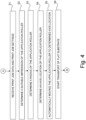
- Fig. 3 discloses an example of a first method according to the invention.
- This invention contains a step-wise approach using sensor data, print job settings, hardness data and a calculation to come to a perfect impression without operator interaction and without generating waste substrates, while working on normal coating speed.
- the coating speed may be tuned to the printing speed.
- the first method starts in a starting point A which leads to a first step S1.
- the control system receives print job data and print job settings from a printing system which has received the print job.
- the print job data and print job settings comprise the type of print medium, a thickness of the print medium and other media properties.
- the print job data and the print job settings may be received via a network connected to the controller of the coater.
- a second step S2 the control system determines a suitable impression of the application roller by means of received print job settings as explained here-above.
- a third step S3 the first sensor determines a radius of the application roller.
- a fourth step S4 the control system determines an axis location of the application roller having a distance of the radius of the application roller plus a nominal thickness of the flat substrate read from the print job data minus the determined suitable impression from the supporting roller surface.
- a fifth step S5 the motor system of the coater - instructed by the control system - automatically moving the application roller to the determined axis location.
- a sixth step S6 the transport of the flat substrate from the entry station in-between the supporting roller and the application roller towards the end station is started.
- the method ends in an end point B.
- additional steps T1 - T3 are added to the steps S1 - S6 of the first method.
- the additional steps T1 - T3 are executed for every piece of substrate arriving at the entry station of the coater.
- the application module comprises a second sensor for determining an actual thickness of the flat substrate.
- the second sensor determines an actual thickness of the flat substrate.
- control system adjusts the determined axis location of the application roller by using the actual thickness of the flat substrate instead of the initially used nominal thickness of the flat substrate.
- a third additional step T3 the motor system moves by means of instructions received from the control system of the coater the application roller to the adjusted axis location.
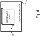
- FIG. 5 schematically shows a non-transitory software medium 50 according to the invention.
- the software medium 50 comprises executable code 52 configured to, when executed, perform the method according to the invention, e.g. as described with respect to either the coating system 1 shown in FIG. 1 or the method of controlling the printing system 1 according to the present invention shown in Fig. 4 and/or according to any of the variants and modifications of the coating system 1 and/or of the method described herein.
- the non-transitory software medium 50 may, specifically, be formed as a CD or a CD-ROM, a DVD or a DVD-ROM, a BluRay disc or a BluRay-ROM disc, a magnetic hard drive, a solid state disk (SSD) hard drive, a USB memory device and so on.
Landscapes
- Engineering & Computer Science (AREA)
- Mechanical Engineering (AREA)
- Coating Apparatus (AREA)
Abstract
Description
- The present invention relates to a method for coating a flat substrate by a coater comprising an entry station for receiving the flat substrate to be coated, a control system for controlling print job data, print job settings and coater settings, an application module comprising a supporting roller for supporting the flat substrate and an application roller for transferring a layer of coating from a surface of the application roller towards the flat substrate, and an end station for storing the flat substrate when coated.
- Roll coating is a method of applying thin films of finishing material to flat substrate of wood, metal, carton, heavy-weight paper or plastic. The flat substrate may be a printed media. The principle of roll coating is well known and based on the physics of transferring a layer of coating from the surface of a roller to the surface of a substrate. Roll coating is a highly effective method, precise in application and environmentally friendly and offering nearly 100 % of transfer efficiency.
- The most common type of roll coater is the differential direct style where the moving components are individually and manually adjusted in speed and direction. In this way an operator controls the coating process. The process of transporting a layer of coating from the roll requires several key components. A conveyor belt or rolling system moves the substrate under the application roller to enable the film transfer. The application roller carries the coating film which will be transferred to the substrate. The application roller is covered with various materials and densities to facilitate the coating application. The application roller is exchangeable since, in the case that coating is done by means of substrates with knock out areas (places where no coating is wanted), each substrate length has its corresponding application roller diameter.
- The coater comprises an applying mechanism which is configured to apply the coating to the application roller. For example, a known application mechanism comprises a metal doctor roller or metering roller which works in conjunction with the application roller to form a packet of coating called a nip. The film thickness on the application roller may be determined by the distance between the two rollers and the speed and rotation direction of each roller. The film thickness may also be determined by a mechanism which transfers the coating from a bulk storage to the application roller, for example by means of an anilox roller.
- Machine set up begins with an initial manual adjustment of the application roller to a desired height. Typically the application roller is set to a light impression with respect to the substrate. Conveyor and application roll speed are set and synchronized based upon production requirements.
- When a substrate is coated, the coated substrate is transferred to the end station. The weight of the coating film may be determined by a scale. From the resulting weight coating adjustments can be determined.
- However, such adjustments are made manually by the operator by means of the nip, the roller speeds and the height of the application roll. When a new print job is loaded, it usually takes time, operator skills and waste flat substrates to install the correct application roller height in the coater (a flexographic unit) to achieve perfect impression on the flat substrate. Up until now the printing speed is slowed down, so the operator can look at the print result while adjusting the printing roller height until he/she judged the impression to be good. However, under impression leads to an incomplete coating layer and over impression could lead to damages at the application roller or damages at the substrate.
- The control system may also be referred to as controller or as control unit hereinafter.
- It is the objective of the present invention to minimize the time needed for the run-in of a print job and to prevent the waste of pieces of flat substrate during a run-in of a print job.
- In accordance with the present invention, a method for coating the flat substrate is provided wherein the coater comprises a first sensor for determining a radius of the application roller and the application module is configured to transport the flat substrate from the entry station in-between the supporting roller and the application roller towards the end station, wherein the method comprises the steps of a) the control system receiving print job data and print job settings, b) the control system determining a suitable impression of the application roller by means of received print job settings, c) the first sensor determining a radius of the application roller, d) determining an axis location of the application roller having a distance of the radius of the application roller plus a nominal thickness of the flat substrate read from the print job data minus the determined suitable impression from the supporting roller surface, e) automatically moving the application roller to the determined axis location, and f) starting the transport of the flat substrate from the entry station in-between the supporting roller and the application roller towards the end station.
- By doing so, when a new print job is loaded, it takes less time, less operator skills and less waste substrates to install the correct application roller height in the coater to achieve a perfect impression on the substrate. Less or even no waste of substrates will occur during the run-in of a print job.
- Instead of the operator entering a diameter of the application roller at each time an application roller is exchanged when a substrate length changes, the first sensor is in place in order to errorlessly, accurately and instantaneously measure the radius of the application roller.
- According to an embodiment the step of the control system determining a suitable impression of the application roller by means of the print job settings comprises the sub-steps of reading from the print job settings a type of the flat substrate, reading a hardness range for the type of flat substrate from a set of hardness ranges for types of media stored in memory of the control system, and deriving from the read hardness range a suitable impression of the application roller.
- According to an embodiment the application module comprises a second sensor for determining an actual thickness of the flat substrate and the method comprises the steps of determining an actual thickness of the flat substrate and adjusting the determined axis location of the application roller and automatically moving the application roller to the adjusted axis location.
- According to an embodiment the second sensor is positioned between the entry station and the application module or between the application module and the end station. Preferably the second sensor is positioned between the entry station and the application module.
- According to an embodiment the flat substrate is a print medium which is printed upon by a printer connected to the coater. The printer proceeds the coater in a production process of printing upon a print medium which is after printing coated by the coater in order to deliver a coated and printed print medium. Hereinafter and hereinbefore the printed print medium may also be called a printed medium.
- The present invention also relates to a coater comprising an entry station for entering a flat substrate to be coated, a control system for controlling print job data, print job settings and coater settings, an application module comprising a supporting roller for supporting the flat substrate and an application roller for transferring a layer of coating from a surface of the application roller towards the flat substrate, an end station for storing the flat substrate when coated, and a first sensor for determining a radius of the application roller, wherein the application module is configured to transport the flat substrate from the entry station in-between the supporting roller and the application roller towards the end station, and the coater is configured to perform the steps of the method according to the present invention. The coater is provided with a moving mechanism in order to move the application roller in a height direction.
- According to an embodiment the application module comprises a second sensor for determining an actual thickness of the flat substrate, and the coater is configured to determine an actual thickness of the flat substrate and to adjust the determined axis location of the application roller and to automatically move the application roller to the adjusted axis location.
- The present invention further relates to a software product comprising program code on a machine-readable medium, which program code, when loaded into a control system of a coater, causes the coater to execute the steps of the method according to the present invention.
- Further scope of applicability of the present invention will become apparent from the detailed description given hereinafter. However, it should be understood that the detailed description and specific examples, while indicating preferred embodiments of the present invention, are given by way of illustration only, since various changes and modifications within the spirit and scope of the present invention will become apparent to those skilled in the art from this detailed description.
- The present invention will become more fully understood from the detailed description given herein below and the accompanying drawings which are given by way of illustration only, and thus are not limitative of the present invention, and wherein:
-
Fig. 1 is a schematic drawing of a coater configured to coat flat substrates according to the present invention; -
Fig. 2 is a schematic drawing of the application module comprised in the coater according to the present invention; -
Fig. 3 is a schematic block diagram illustrating the control system of the coater according to the present invention; -
Fig. 4 is a schematic block diagram illustrating the steps of a first method according to the present invention; and -
Fig. 5 is a diagram of a software product according to the present invention. - The present invention will now be described with reference to the accompanying drawings, wherein the same reference numerals have been used to identify the same or similar elements throughout the several views.
-
Fig. 1 is a schematic drawing of acoater 1 configured to coatflat substrates 10 according to the present invention. Thecoater 1 comprises anentry station 11 for receiving 19 theflat substrate 10 to be coated, acontrol system 14 for controlling print job data, print job settings and coater settings, anapplication module 12 for transferring a layer of coating towards theflat substrate 10, and anend station 13 for storing theflat substrate 10 when coated. Thecontrol system 14 is configured to receive print job data and print job settings from a printer, i.e. from a print controller comprised in aprinting system 15 which is wired 16 or wireless connected to thecoater 1. -
Fig. 2 is a schematic drawing of theapplication module 12 comprised in thecoater 1 according to the present invention. Theapplication module 12 comprises a supportingroller 26 having afirst radius 25. The supportingroller 26 supports theflat substrate 10 when moving over thesupport roller 10 by means of aconveyor belt 23. Theapplication module 12 also comprises anapplication roller 27 for transferring a layer of coating from a surface of theapplication roller 27 towards theflat substrate 10. Afirst sensor 29 is positioned in theapplication module 12 in order to determine aradius 28 of theapplication roller 27. The application module is configured to transport theflat substrate 10 moving in adirection 103 from the entry station 11 (SeeFig. 1 ) in-between the supportingroller 26 and theapplication roller 27 towards the end station 13 (SeeFig. 1 ). - The applying mechanism for applying the coating on the
application roller 27 is not shown inFig. 2 and not described hereinafter, since such applying mechanisms are known and not relevant for the present invention. - The
control system 14 is configured to determine a suitable impression of theapplication roller 27 by means of received print job settings. Thefirst sensor 29 is configured to determine aradius 28 of theapplication roller 27 as a distance R0 from a blanket surface of theapplication roller 27 to thecore 273 of theapplication roller 27. The print job settings comprise a type of theflat substrate 10. Thecontrol system 14 is configured to read a hardness range for the type offlat substrate 10 from a set of hardness ranges for types of media stored in memory of thecontrol system 14. Thecontrol system 14 is also configured to derive from the read hardness range a suitable impression xi of theapplication roller 27. InFig. 2 the impression xi of theapplication roller 27 is indicated by thearrows controller 14. A hardness ranges may be expressed in so-called Shore A hardness range, for example 25-35, 35-60 or 60-80. The Shore A hardness scale ranges from 0 to 100. Harder materials have higher Shore A values than softer materials. In practice the value for the impression xi depends on the hardness range of the substrate and may be for example approximately one millimeter. - The
controller system 14 is configured to determine an axis location of theapplication roller 27 having a distance D which is the quantity R0 of theradius 28 of theapplication roller 27 plus a nominal thickness to of theflat substrate 10 read from the print job settings minus the determined suitable impression x1 of theapplication roller 27 from the upper surface of the supportingroller 26. Expressed in a formula this is equivalent to:
- The height H1 of the upper surface of the supporting
roller 26 may be determined by theheight 21 of the supportingroller 26 having a value h1 plus a quantity R1 of theradius 25 of the supportingroller 26. Expressed in a formula this is equivalent to:
- The value H0 of the
height 22 of theaxis location 273 of theapplication roller 27 can be expressed as:
- The
heights plane 20 which may be for example the floor on which the coater is placed, a transportation belt on which the flat substrates arrive or a supporting structure of the transportation belt. - The
control system 14 of thecoater 1 is configured to send instructions to a motor system (not shown) of thecoater 1 in order to automatically move theaxis 273 of theapplication roller 27 to the determined axis location. - Once the
application roller 27 is arrived at the correct location, i.e. the correct height, the transport of theflat substrate 10 from theentry station 11 in-between the supportingroller 26 and theapplication roller 27 towards theend station 13 can start. - According to a further embodiment the
application module 12 comprises asecond sensor 24 for determining an actual thickness t1 of the flat substrate 10 - indicated by thearrows flat substrate 10, the formula expressions become:

- The adjustment of D or H0 may take place for every substrate in order to keep the impression for each substrate on a good level. Adjustment of D or H0 takes place at a predetermined time after measuring the actual thickness t1 by the
sensor 24 and before the arrival of thesubstrate 10 in-between the supportingroller 25 and theapplication roller 27. The predetermined time depends on the horizontal distance between thesecond sensor 24 and the axis of the supporting roller 26 (which equals the horizontal distance between thesecond sensor 24 and the axis of the application roller 27), a speed of theconveyor belt 23 and a time period needed to move theapplication roller 27 to the redeterminedaxis location 273 of theapplication roller 27. - The
control system 14 is configured to adjust thedetermined axis location 273 of theapplication roller 27 and to instruct the motor system (not shown) to move theapplication roller 27 to the adjustedaxis location 273. Preferably the move of theapplication roller 27 is planned in-between the flat substrates lying on theconveyor belt 23. Nevertheless a move of theapplication roller 27 may overlap with an end of the previous flat substrate in-between the supportingroller 26 and theapplication roller 27. - Preferably the
second sensor 24 inFig. 2 is positioned between theentry station 11 and theapplication module 12. Nevertheless a position of the second sensor may be envisioned between theapplication module 12 and theend station 13. - The
flat substrate 10 may be a print medium which is printed upon by theprinter 15 or by another printer as long as the printer is digitally connected to thecoater 1 for transferring print job data and print job settings. Theprinter 15 may also physically connected to thecoater 1 by placing theprinter 15 in-line with thecoater 1 in order to establish a smooth transport of the printedflat substrate 10 from theprinter 15 to theentry station 11 of thecoater 1. - An embodiment of the
control unit 14 is in more detail presented inFig. 3 . As shown inFig. 3 , thecontrol unit 14 comprises a Central Processing Unit (CPU) 31, a Random Access Memory (RAM) 33, a Read Only Memory (ROM) 34, anetwork unit 36, aninterface unit 37 and a hard disk (HD) 35. The aforementioned units 31 - 37 are interconnected through abus system 38. However, thecontrol unit 14 may also be a distributed control unit. - The
CPU 31 controls thecoater 1 in accordance with control programs stored in theROM 34 or on theHD 35 and the localuser interface panel 11. Instead of local user interface panel on the coater, a user interface may be envisioned that is installed close to and digitally connected to the coater, for example a user interface which is integrated with the user interface of a printing system from which the print jobs are received. TheROM 34 stores programs and data such as boot program, set-up program, various set-up data or the like, which are to be read out and executed by theCPU 31. Thehard disk 35 is an example of a non-volatile storage unit for storing and saving programs and data which make theCPU 31 execute a coating process to be described later in the method according to the present invention. Thehard disk 35 also comprises an area for saving the data of externally submitted print jobs, like print job settings. The programs and data on theHD 35 are read out onto theRAM 33 by theCPU 31 as needed. TheRAM 33 has an area for temporarily storing the programs and data read out from theROM 34 andHD 35 by theCPU 31, and a work area which is used by theCPU 31 to execute various processes. Theinterface unit 37 connects thecontrol unit 14 to theclient device 21 and to theprinting system 15. Thecontrol unit 14 may be is connected via an OPC UA interface to a print controller of theprinter 15. OPC Unified Architecture (OPC UA) is a machine-to-machine communication protocol used for industrial automation and developed by the OPC Foundation. The OPC UA platform is an platform-independent service-oriented architecture that integrates individual OPC Classic specifications into an extensible framework. Thenetwork unit 36 connects thecontrol unit 14 to the network N and is designed to provide communication with workstations and with other devices reachable via the network N. The print job settings contains a plurality of media properties of the print medium, i.e. the flat substrate, upon which the coating will be applied. Media properties are for example a type of print medium, a hardness of the print medium and a thickness of the print medium. -
Fig. 3 discloses an example of a first method according to the invention. This invention contains a step-wise approach using sensor data, print job settings, hardness data and a calculation to come to a perfect impression without operator interaction and without generating waste substrates, while working on normal coating speed. When a printer is in-line with and placed before the entry station of the coater the coating speed may be tuned to the printing speed. - The first method starts in a starting point A which leads to a first step S1.
- In the first step S1 the control system receives print job data and print job settings from a printing system which has received the print job. The print job data and print job settings comprise the type of print medium, a thickness of the print medium and other media properties. The print job data and the print job settings may be received via a network connected to the controller of the coater.
- In a second step S2 the control system determines a suitable impression of the application roller by means of received print job settings as explained here-above.
- In a third step S3 the first sensor determines a radius of the application roller.
- In a fourth step S4 the control system determines an axis location of the application roller having a distance of the radius of the application roller plus a nominal thickness of the flat substrate read from the print job data minus the determined suitable impression from the supporting roller surface.
- In a fifth step S5 the motor system of the coater - instructed by the control system - automatically moving the application roller to the determined axis location.
- In a sixth step S6, the transport of the flat substrate from the entry station in-between the supporting roller and the application roller towards the end station is started.
- The method ends in an end point B.
- According to a second method of the present invention, additional steps T1 - T3 are added to the steps S1 - S6 of the first method. The additional steps T1 - T3 are executed for every piece of substrate arriving at the entry station of the coater. The application module comprises a second sensor for determining an actual thickness of the flat substrate.
- In the first additional step T1 the second sensor determines an actual thickness of the flat substrate.
- In the second additional step T2 the control system adjusts the determined axis location of the application roller by using the actual thickness of the flat substrate instead of the initially used nominal thickness of the flat substrate.
- In a third additional step T3 the motor system moves by means of instructions received from the control system of the coater the application roller to the adjusted axis location.
-
FIG. 5 schematically shows anon-transitory software medium 50 according to the invention. Thesoftware medium 50 comprisesexecutable code 52 configured to, when executed, perform the method according to the invention, e.g. as described with respect to either thecoating system 1 shown inFIG. 1 or the method of controlling theprinting system 1 according to the present invention shown inFig. 4 and/or according to any of the variants and modifications of thecoating system 1 and/or of the method described herein. - The
non-transitory software medium 50 may, specifically, be formed as a CD or a CD-ROM, a DVD or a DVD-ROM, a BluRay disc or a BluRay-ROM disc, a magnetic hard drive, a solid state disk (SSD) hard drive, a USB memory device and so on. - Although specific embodiments of the invention are illustrated and described herein, it will be appreciated by those of ordinary skill in the art that a variety of alternate and/or equivalent implementations exist. It should be appreciated that the exemplary embodiment or exemplary embodiments are examples only and are not intended to limit the scope, applicability, or configuration in any way. Rather, the foregoing summary and detailed description will provide those skilled in the art with a convenient road map for implementing at least one exemplary embodiment, it being understood that various changes may be made in the function and arrangement of elements described in an exemplary embodiment without departing from the scope as set forth in the appended claims and their legal equivalents. Generally, this application is intended to cover any adaptations or variations of the specific embodiments discussed herein.
- It will also be appreciated that in this document the terms "comprise", "comprising", "include", "including", "contain", "containing", "have", "having", and any variations thereof, are intended to be understood in an inclusive (i.e. non-exclusive) sense, such that the process, method, device, apparatus or system described herein is not limited to those features or parts or elements or steps recited but may include other elements, features, parts or steps not expressly listed or inherent to such process, method, article, or apparatus. Furthermore, the terms "a" and "an" used herein are intended to be understood as meaning one or more unless explicitly stated otherwise. Moreover, the terms "first", "second", "third", etc. are used merely as labels, and are not intended to impose numerical requirements on or to establish a certain ranking of importance of their objects.
- The present invention being thus described, it will be obvious that the same may be varied in many ways. Such variations are not to be regarded as a departure from the spirit and scope of the present invention, and all such modifications as would be obvious to one skilled in the art are intended to be included within the scope of the following claims.
Claims (8)
- A method for coating a flat substrate by a coater (1) comprising an entry station (11) for receiving the flat substrate (10) to be coated, a control system (14) for controlling print job data, print job settings and coater settings, an application module (12) comprising a supporting roller (26) for supporting the flat substrate (10) and an application roller (27) for transferring a layer of coating from a surface of the application roller (27) towards the flat substrate (10), an end station (13) for storing the flat substrate (10) when coated, and a first sensor (29) for determining a radius (28) of the application roller (27), wherein the application module (12) is configured to transport the flat substrate (10) from the entry station (11) in-between the supporting roller (26) and the application roller (27) towards the end station (13), wherein the method comprises the steps of a) the control system (14) receiving print job data and print job settings, b) the control system (14) determining a suitable impression (xi) of the application roller (27) by means of received print job settings, c) the first sensor (29) determining a radius (28) of the application roller (27), d) determining an axis location (273) of the application roller (27) having a distance (D) of the radius (28) of the application roller (27) plus a nominal thickness (t0) of the flat substrate (10) read from the print job data minus the determined suitable impression (xi) from the supporting roller surface, e) automatically moving the application roller (27) to the determined axis location (273), and f) starting the transport of the flat substrate (10) from the entry station (11) in-between the supporting roller (26) and the application roller (27) towards the end station (13).
- Method according to claim 1, wherein the step of the control system determining a suitable impression (xi) of the application roller (27) by means of the print job settings comprises the sub-steps of reading from the print job settings a type of the flat substrate (10), reading a hardness range for the type of flat substrate (10) from a set of hardness ranges for types of media stored in memory of the control system (14), and deriving from the read hardness range a suitable impression (xi) of the application roller (27).
- Method according to claim 1 or 2, wherein the application module comprises a second sensor (24) for determining an actual thickness (t1) of the flat substrate (10) and the method comprises the steps of determining an actual thickness (t1) of the flat substrate (10) and adjusting the determined axis location 273 of the application roller (27) and moving the application roller (27) to the adjusted axis location (273).
- Method according to claim 3, wherein the second sensor (24) is positioned between the entry station (11) and the application module (12) or between the application module (12) and the end station (13).
- Method according to any one of the preceding claims, wherein the flat substrate (10) is a print medium which is printed upon by a printer (15) connected to the coater (1).
- A coater (1) comprising an entry station (11) for entering a flat substrate (10) to be coated, a control system (14) for controlling print job data, print job settings and coater settings, an application module (12) comprising a supporting roller (26) for supporting the flat substrate (10) and an application roller (27) for transferring a layer of coating from a surface of the application roller (27) towards the flat substrate (10), an end station (13) for storing the flat substrate (10) when coated, and a first sensor (29) for determining a radius (28) of the application roller (27), wherein the application module (12) is configured to transport the flat substrate (10) from the entry station (11) in-between the supporting roller (26) and the application roller (27) towards the end station (13), and the coater (1) is configured to perform the steps of the method according to claim 1 or 2.
- A coater according to claim 6, wherein the application module (12) comprises a second sensor (24) for determining an actual thickness (t1) of the flat substrate (10), and the coater (1) is configured to perform the steps of the method according to claim 3 or 4.
- A software product comprising program code (52) on a machine-readable medium (50), which program code (52), when loaded into a control system of a coater, causes the coater to execute the steps of the method according to any of the claims 1 - 5.
Priority Applications (2)
| Application Number | Priority Date | Filing Date | Title |
|---|---|---|---|
| EP23206362.8A EP4545189A1 (en) | 2023-10-27 | 2023-10-27 | A method and coater for coating of a flat substrate |
| US18/917,115 US20250135487A1 (en) | 2023-10-27 | 2024-10-16 | Method and coater for coating of a flat substrate |
Applications Claiming Priority (1)
| Application Number | Priority Date | Filing Date | Title |
|---|---|---|---|
| EP23206362.8A EP4545189A1 (en) | 2023-10-27 | 2023-10-27 | A method and coater for coating of a flat substrate |
Publications (1)
| Publication Number | Publication Date |
|---|---|
| EP4545189A1 true EP4545189A1 (en) | 2025-04-30 |
Family
ID=88598674
Family Applications (1)
| Application Number | Title | Priority Date | Filing Date |
|---|---|---|---|
| EP23206362.8A Pending EP4545189A1 (en) | 2023-10-27 | 2023-10-27 | A method and coater for coating of a flat substrate |
Country Status (2)
| Country | Link |
|---|---|
| US (1) | US20250135487A1 (en) |
| EP (1) | EP4545189A1 (en) |
Citations (5)
| Publication number | Priority date | Publication date | Assignee | Title |
|---|---|---|---|---|
| US5466291A (en) * | 1993-12-29 | 1995-11-14 | Mmt Manufacturing Corp. | Stand alone coating apparatus for printed material and method of operation thereof |
| US20160236225A1 (en) * | 2013-10-24 | 2016-08-18 | Hewlett-Packard Development Company, L.P. | Coater |
| KR20180092282A (en) * | 2017-02-08 | 2018-08-17 | 도요타 지도샤(주) | Manufacturing method of paste-layer-attached sheet and coating applicator |
| US20200324548A1 (en) * | 2019-04-15 | 2020-10-15 | Ricoh Company, Ltd. | Coating apparatus and image forming system including same |
| US20220388021A1 (en) * | 2019-11-21 | 2022-12-08 | Contiweb B.V. | Coating Device and Method Using Rollers |
Family Cites Families (3)
| Publication number | Priority date | Publication date | Assignee | Title |
|---|---|---|---|---|
| KR100350986B1 (en) * | 2000-02-21 | 2002-08-28 | 삼성전자 주식회사 | Printer and method of controlling the gap of fusing roller |
| DE102016110648A1 (en) * | 2016-06-09 | 2017-12-14 | Océ Holding B.V. | Method and control unit for setting an application unit of a printing system |
| CN114042610B (en) * | 2021-12-17 | 2023-10-27 | 无锡氿文科技有限公司 | Non-contact plate coating method and coater |
-
2023
- 2023-10-27 EP EP23206362.8A patent/EP4545189A1/en active Pending
-
2024
- 2024-10-16 US US18/917,115 patent/US20250135487A1/en active Pending
Patent Citations (5)
| Publication number | Priority date | Publication date | Assignee | Title |
|---|---|---|---|---|
| US5466291A (en) * | 1993-12-29 | 1995-11-14 | Mmt Manufacturing Corp. | Stand alone coating apparatus for printed material and method of operation thereof |
| US20160236225A1 (en) * | 2013-10-24 | 2016-08-18 | Hewlett-Packard Development Company, L.P. | Coater |
| KR20180092282A (en) * | 2017-02-08 | 2018-08-17 | 도요타 지도샤(주) | Manufacturing method of paste-layer-attached sheet and coating applicator |
| US20200324548A1 (en) * | 2019-04-15 | 2020-10-15 | Ricoh Company, Ltd. | Coating apparatus and image forming system including same |
| US20220388021A1 (en) * | 2019-11-21 | 2022-12-08 | Contiweb B.V. | Coating Device and Method Using Rollers |
Also Published As
| Publication number | Publication date |
|---|---|
| US20250135487A1 (en) | 2025-05-01 |
Similar Documents
| Publication | Publication Date | Title |
|---|---|---|
| US6450097B1 (en) | Method of regulating inking when printing with a printing machine | |
| GB2202490A (en) | Setting up ink distribution profiles in printing machines | |
| US20250135487A1 (en) | Method and coater for coating of a flat substrate | |
| JPH08183167A (en) | Method for forming ink film thickness suitable for running-on in inking unit | |
| CN102556720B (en) | Method and arrangement in connection with winder drive | |
| JP6843390B2 (en) | Coating device | |
| US6493012B2 (en) | Method and apparatus for setting register on a multicolor printing machine by time independent allocation of positions of image productions to printing substrates | |
| KR20230050981A (en) | Control system for web velocity and method for controlling web velocity using the same | |
| CN109963718B (en) | Roll-to-roll printing unit | |
| US11003406B2 (en) | System and method for managing print jobs by determining optimal printers and comparing itemized actual and estmated costs | |
| US10007872B2 (en) | Media processing system with scheduler | |
| KR100330434B1 (en) | Plate feeding speed controlling apparatus for tandem rolling mill | |
| US6485777B1 (en) | Method and device for coating sheets | |
| US20210146702A1 (en) | Substrate selection methods | |
| JP2906838B2 (en) | Tension control device for winding / unwinding machine | |
| KR100954444B1 (en) | Width Position Displacement Control of Web | |
| US20040144272A1 (en) | Multiple-Stand Gravure Printing Machine and Gravure Printing Process | |
| JPS5978854A (en) | Ink supply regulator for printing press | |
| JP3403753B2 (en) | Coating amount profile control device and coating method | |
| JP2003212406A (en) | Dancer control device | |
| US8720338B2 (en) | Process for controlling the quantity of ink applied to a material being printed and corresponding device | |
| JP2001071307A (en) | Plate material manufacturing apparatus and manufacturing method | |
| JP6088475B2 (en) | Control method of coating film thickness | |
| JPS5926220A (en) | Control on supply amount of raw materials in calendering | |
| JPH05116823A (en) | Tension control device for sheet-like material |
Legal Events
| Date | Code | Title | Description |
|---|---|---|---|
| PUAI | Public reference made under article 153(3) epc to a published international application that has entered the european phase |
Free format text: ORIGINAL CODE: 0009012 |
|
| STAA | Information on the status of an ep patent application or granted ep patent |
Free format text: STATUS: THE APPLICATION HAS BEEN PUBLISHED |
|
| AK | Designated contracting states |
Kind code of ref document: A1 Designated state(s): AL AT BE BG CH CY CZ DE DK EE ES FI FR GB GR HR HU IE IS IT LI LT LU LV MC ME MK MT NL NO PL PT RO RS SE SI SK SM TR |
|
| STAA | Information on the status of an ep patent application or granted ep patent |
Free format text: STATUS: REQUEST FOR EXAMINATION WAS MADE |
|
| 17P | Request for examination filed |
Effective date: 20251030 |
|
| GRAP | Despatch of communication of intention to grant a patent |
Free format text: ORIGINAL CODE: EPIDOSNIGR1 |
|
| STAA | Information on the status of an ep patent application or granted ep patent |
Free format text: STATUS: GRANT OF PATENT IS INTENDED |
|
| RIC1 | Information provided on ipc code assigned before grant |
Ipc: B05C 1/08 20060101AFI20260204BHEP Ipc: B41J 11/00 20060101ALI20260204BHEP Ipc: B41F 23/08 20060101ALI20260204BHEP |
|
| INTG | Intention to grant announced |
Effective date: 20260211 |