EP4545123A2 - Aerosol generation device and set - Google Patents
Aerosol generation device and set Download PDFInfo
- Publication number
- EP4545123A2 EP4545123A2 EP25157889.4A EP25157889A EP4545123A2 EP 4545123 A2 EP4545123 A2 EP 4545123A2 EP 25157889 A EP25157889 A EP 25157889A EP 4545123 A2 EP4545123 A2 EP 4545123A2
- Authority
- EP
- European Patent Office
- Prior art keywords
- receptacle
- protrusion
- generation device
- aerosol generation
- internal surface
- Prior art date
- Legal status (The legal status is an assumption and is not a legal conclusion. Google has not performed a legal analysis and makes no representation as to the accuracy of the status listed.)
- Pending
Links
Images



Classifications
-
- A—HUMAN NECESSITIES
- A24—TOBACCO; CIGARS; CIGARETTES; SIMULATED SMOKING DEVICES; SMOKERS' REQUISITES
- A24F—SMOKERS' REQUISITES; MATCH BOXES; SIMULATED SMOKING DEVICES
- A24F40/00—Electrically operated smoking devices; Component parts thereof; Manufacture thereof; Maintenance or testing thereof; Charging means specially adapted therefor
- A24F40/40—Constructional details, e.g. connection of cartridges and battery parts
- A24F40/46—Shape or structure of electric heating means
- A24F40/465—Shape or structure of electric heating means specially adapted for induction heating
-
- A—HUMAN NECESSITIES
- A24—TOBACCO; CIGARS; CIGARETTES; SIMULATED SMOKING DEVICES; SMOKERS' REQUISITES
- A24F—SMOKERS' REQUISITES; MATCH BOXES; SIMULATED SMOKING DEVICES
- A24F40/00—Electrically operated smoking devices; Component parts thereof; Manufacture thereof; Maintenance or testing thereof; Charging means specially adapted therefor
- A24F40/40—Constructional details, e.g. connection of cartridges and battery parts
-
- A—HUMAN NECESSITIES
- A24—TOBACCO; CIGARS; CIGARETTES; SIMULATED SMOKING DEVICES; SMOKERS' REQUISITES
- A24F—SMOKERS' REQUISITES; MATCH BOXES; SIMULATED SMOKING DEVICES
- A24F40/00—Electrically operated smoking devices; Component parts thereof; Manufacture thereof; Maintenance or testing thereof; Charging means specially adapted therefor
- A24F40/40—Constructional details, e.g. connection of cartridges and battery parts
- A24F40/42—Cartridges or containers for inhalable precursors
-
- A—HUMAN NECESSITIES
- A24—TOBACCO; CIGARS; CIGARETTES; SIMULATED SMOKING DEVICES; SMOKERS' REQUISITES
- A24F—SMOKERS' REQUISITES; MATCH BOXES; SIMULATED SMOKING DEVICES
- A24F40/00—Electrically operated smoking devices; Component parts thereof; Manufacture thereof; Maintenance or testing thereof; Charging means specially adapted therefor
- A24F40/40—Constructional details, e.g. connection of cartridges and battery parts
- A24F40/48—Fluid transfer means, e.g. pumps
-
- A—HUMAN NECESSITIES
- A24—TOBACCO; CIGARS; CIGARETTES; SIMULATED SMOKING DEVICES; SMOKERS' REQUISITES
- A24D—CIGARS; CIGARETTES; TOBACCO SMOKE FILTERS; MOUTHPIECES OF CIGARS OR CIGARETTES; MANUFACTURE OF TOBACCO SMOKE FILTERS OR MOUTHPIECES
- A24D1/00—Cigars; Cigarettes
- A24D1/20—Cigarettes specially adapted for simulated smoking devices
Definitions
- the invention relates to an aerosol generation device and an aerosol generation set comprising the device and a replaceable article comprising vaporizable material.
- a vaporizable material such as tobacco
- susceptors which are embedded in the vaporizable material and are heated by one or more coils surrounding a receptacle adapted to accommodate the replaceable article.
- susceptors are used in induction heating devices that are heated by eddy currents produced by surrounding coils and induced within the susceptors.
- uniform heat distribution within the vaporizable material is an issue, as, firstly, cold air is continuously supplied from an air inlet. Secondly, the temperature is usually particularly high immediately around the susceptors, which are usually formed thin and generally extend in an airflow direction between the air inlet and an air outlet. This also holds true for other heating methods, such as those involving heating tracks, cups and/or blades. In these cases, the vaporizable material does not contain a heating element like a susceptor, but the above-described thermal gradient across the vaporizable material between inlet and outlet essentially remains the same.
- This is configured to operate with a replaceable article, such as a tobacco stick, comprising a storage compartment containing a vaporizable material, such as tobacco, the storage compartment defining an air flow path extending between an inlet and an air outlet through the vaporizable material.
- the aerosol generation device comprises a receptacle extending along a receptacle axis and defining a receptacle internal surface and being configured to receive the replaceable article in a space delimited by the receptacle internal surface so that the airflow path extends along the receptacle axis.
- a heating system configured to heat the replaceable article received in the receptacle is provided.
- the receptacle internal surface comprises at least one protrusion protruding from the receptacle internal surface and configured to reduce the cross-sectional area of the receptacle so as to compress a part of the airflow path of the storage compartment, when the article is received in the receptacle.
- the or each protrusion defines a protrusion surface adjacent the receptacle internal surface forming an angle with the receptacle internal surface greater than 100 degrees along the entire protrusion in an airflow direction. Otherwise, the or each protrusion defines a protrusion surface adjacent the receptacle internal surface forming an angle with the receptacle internal surface greater than 100 degrees along at least an/the ascending portion of the protrusion in an airflow direction. This will avoid unwanted turbulences and recirculating eddies or vortices downstream of the protrusions, which are disadvantageous as vapor can be trapped in the vortices and condense.
- the smooth shape also helps to maintain good contact between the receptacle and the replaceable article, which is for example advantageous, when resistive heating is utilized at the wall of the receptacle.
- Preferred angle ranges at the point, as seen in a longitudinal cut view, where the protrusion emerges from the internal wall, are 100 to 175 degrees, with 130 to 170 degrees being preferred.
- the feature that the protrusion surface forms an angle with the receptacle internal surface which is greater than 100 degrees along the entire protrusion in an airflow direction may mean that the value of the angle remains at values greater than 100 degrees along the entire protrusion in the airflow direction.
- this feature may imply that the protrusion surface becomes shallower along the airflow direction compared to the angle at the point where the protrusion emerges from the internal wall, as long as the angle remains greater than 100 degrees along the entire protrusion in the airflow direction.
- the feature that the protrusion surface forms an angle with the receptacle internal surface which is greater than 100 degrees along the entire protrusion in an airflow direction may mean that an angle between a straight line (tangent) at each point of the profile of the protrusion in a cross section of the protrusion along the airflow direction and the receptacle internal surface is greater than 100 degrees.
- an angle between a straight line at a point close to the top portion of the protrusion and the receptacle internal surface may be close to 180 degrees, and thus greater than 100 degrees, because the straight line may be close to parallel with the receptacle internal surface in this case, as seen along the airflow direction.
- the airflow direction may be understood as the direction from the air inlet to the air outlet in which air flows during use of the aerosol generation device.
- the airflow direction may be parallel to the receptacle axis.
- the described angle further provides a "smooth" shape of the protrusion, which for example allows the replaceable article to be inserted and removed from the receptacle without being damaged.
- the effect, on which the present invention is based is similar to that of a venturi tube, as the compression or reduction in cross-sectional area of the airflow path leads to an acceleration of the air flowing through the replaceable article. This will remove heat from, for example, particularly hot areas and transport the heat in the form of heated air to cooler areas. This will make heating more uniform, which is advantageous with regard to an effective usage of the vaporizable material.
- the protrusions additionally have the advantageous effect of securing the replaceable article in place.
- the protrusions can have a radially and/or axially and/or circumferentially identical or different dimensions and/or constant or varying heights and they can be provided at axially and/or circumferentially offset or staggered positions. Further, protrusions having a longitudinal extension can be oriented with this extension parallel to the receptacle axis or with an angle to this axis. It is currently expected that a maximum number of protrusions is 64.
- the shape of the protrusions can also be called aerodynamic.
- the desired effect of accelerating the flow while still promoting laminar or transitional flow can particularly be obtained, when the or each protrusion has a maximum height measured according to an axis perpendicular to the receptacle axis between 2 and 15% of the receptacle diameter, with 5 to 10% of this diameter being preferred.
- the space available for the replaceable article, such as a tobacco stick is decreased by the mentioned values, and the available cross-sectional area is constricted.
- the cross-sectional area can be reduced by 1 to 15%, preferably between 2 and 8%.
- the mentioned values appear particularly suitable for typical dimensions of the receptacle with a diameter of 7 to 7.5 mm, and in particular 7.1 mm, and a length of 37 to 38 mm, in particular 37.5 mm.
- the maximum length of the or each protrusion measured along the receptacle axis is between 5 and 75% of the receptacle length measured according to the receptacle axis, and preferably between 10 and 65% of this length, with 15 to 55% being further preferred.
- the most preferred lengths can be around 20% of said receptacle length.
- the desired "smooth" shape of the or each protrusion can particularly be obtained when it has an ascending portion, top portion and a descending portion.
- the or each protrusion can typically be symmetric, as regards the ascending and descending portion, with respect to the top portion. Nevertheless, also asymmetrical shapes can be chosen.
- an advantageous shape is expected for an ascending portion defining transversal dimensions gradually increasing from the receptacle internal surface until the top portion, and/or the descending portion defining transversal dimensions gradually decreasing from the top portion to the receptacle internal surface.
- protrusions which are arranged on the receptacle internal surface axially and/or circumferentially.
- the or each protrusion is arranged adjacent the air outlet.
- At least one protrusion can also be movable along the receptacle axis. Further, they can be clicked into place by the user, after the article has been inserted into the receptacle. This will help avoiding damage of the replaceable article, in particular a base of a stick-shaped article, which is inserted into the receptacle with the base in front.
- the or each protrusion can also be movable along an axis perpendicular to the receptacle axis, in order to achieve the previously described effect. In any case, it is sufficient, if it protrudes from the receptacle internal surface.
- the protrusion will constitute portions of the internal surface and will be smoothly connected with it, i.e. avoiding sharp edges and implying radii of curvature.
- the invention is particularly useful in connection with an inductive heating system, wherein the storage compartment of the replaceable article comprises at least one susceptor.
- the number of protrusions is equal to the number of susceptors.
- heating can be unified, when a top portion of the or each protrusion faces the downstream end and/or the hottest part of the corresponding susceptor, when the replaceable article is received in the receptacle.
- the heating system may comprise one or more heating elements extending along at least a part of the receptacle internal surface and the contact surface of at least one protrusion.
- a receptacle 10 of an aerosol generation device is essentially tube-shaped and adapted to accommodate a replaceable article, such as a tobacco stick.
- a replaceable article such as a tobacco stick.
- air essentially flows through a tobacco stick along the receptacle axis, and will enter the receptacle 10 at an air inlet 12 in an essentially cold state.
- the tobacco stick includes susceptors adapted to cooperate with one or more induction coils (not shown) around the receptacle so as to be heated and transfer the heat to the surrounding tobacco.
- two protrusions 14 are formed at the same position along the axial direction and at diametrically opposite positions along the circumferential direction. Similar to a Venturi tube, airflow in the area of the protrusions, where the tobacco stick is correspondingly constricted, is accelerated, so that heated air can be quickly transported away from the particularly hot area surrounding the susceptors.
- the protrusions have a smooth cross-sectional geometry, so that no undesired turbulences are created, and a tobacco stick can be inserted, sliding between the protrusions without risking damage of the tobacco stick.
- the protrusions have an asymmetric shape with a steeper ascending portion, as viewed in the direction of flow, and a less steep descending portion. This particularly allows easy insertion of a tobacco stick in a direction opposite to the flow direction.
- plural protrusions for example 12 protrusions are provided equidistantly along the circumference of the receptacle.
- transversal dimensions of the ascending portion increase with a gradient higher as seen in the flow direction, than the gradient, with which these dimensions decrease in the descending portion as can be seen in the center part of Fig. 3 , similar to a drop-shape.
- plural protrusions can also be provided at different axial positions, which can be considered a staggered arrangement.
- protrusions at different axial positions are additionally offset in circumferential direction.
- plural protrusions can also be provided at more than two axial positions, and that the distance between protrusion positions in the circumferential direction can be the same over the entire circumference or can vary.
- any arrangement of protrusions shown in the figures can be chosen with symmetric protrusions as shown in Fig. 1, 2 and 4 , as well as asymmetric protrusions as shown in Fig. 3 , including any further shapes shown in Fig. 5 . In this context, when plural protrusions are present, they can all have the same or different shapes.
- asymmetric fillet combined with a chamfer as ascending portion (C) symmetric fillet (D) asymmetric fillet(E), symmetric chamfer (F) and asymmetric chamfer (D)
- Chevron and arrowhead essentially have a point at one end thereof and their shape as seen in a plan view can be described as essentially triangular.
- a chevron has a cut out as seen in a plan view, on the side opposite the point.
- a chamfer essentially has a flat, inclined surface as seen in a cross-sectional view, and a fillet is essentially oval or elliptic, as seen in a plan view.
- the flow direction will typically be from right to left in Fig. 5 .
- one or more protrusions can be formed by thickening the receptacle wall.
- the receptacle wall can have a uniform wall thickness, and one or more protrusions can be formed as a convex shape inside the receptacle corresponding to a concave shape on the outside thereof.
- each protrusion has a protrusion surface adjacent the receptacle internal surface which forms an angle ⁇ with the receptacle internal surface greater than 100°, especially in the embodiment of Fig.
- each protrusion lacks any surfaces extending "steep" towards the receptacle internal surface which would create unwanted turbulences.
- Figs. 9A and 9B illustrate two different configurations of the protrusion 14.
- the protrusion 14 has a roof-like shape with a linearly ascending portion (portion comprising point A) and a linearly descending portion (portion comprising point B) along the airflow direction (indicated by the arrow).
- the protrusion 14 has a semi-circular shape with an ascending portion becoming gradually shallower (portion comprising point A) and a descending portion becoming gradually steeper (portion comprising point B) along the airflow direction (indicated by the arrow).
- the feature that the protrusion surface forms an angle ⁇ with the receptacle internal surface which is greater than 100 degrees (100°) along the entire protrusion 14 in an airflow direction means that an angle between a straight line (tangent) at each point of the profile of the protrusion 14 in a cross section of the protrusion along the airflow direction and the receptacle internal surface is greater than 100 degrees.
- such straight line (tangent) is exemplarily shown at points A and B by the dashed lines.
- the angle ⁇ is measured with respect to the receptacle internal surface upstream of the protrusion 14 with respect to the airflow direction.
- the angle ⁇ is measured with respect to the receptacle internal surface downstream of the protrusion 14 with respect to the airflow direction. While the angle ⁇ remains the same at each point of the protrusion 14 in the ascending portion in Fig. 9A , it changes, i.e. becomes greater, when going along the airflow direction in the ascending portion of the protrusion 14 shown in Fig. 9B .
- Fig. 6 shows a receptacle 10 with two diametrically protrusions 14 similar to those of Fig. 5D or F .
- Fig. 6 additionally shows a replaceable article 16, such as a tobacco stick accommodated in the receptacle 10 and correspondingly compressed in the area of the protrusions 14. This compression, firstly, moves the tobacco strands 18 closer together in the area of the protrusions 14 and, secondly, bends susceptors 20 accommodated in the replaceable article 16.
- These susceptors 20 may have a curved, convex shape already in the original state, i.e. without being compressed by the protrusions 14.
- the convex shapes of two or more susceptors can face each other towards the center of the replaceable article 16.
- the convex shape shown in the figure can be caused by the compression in the area of the protrusions. 14.
- the cross-sectional area of the replaceable article 16 is smaller in the area of the protrusions 14, so that the flow velocity is increased, and heat is transported at a higher rate than in the area of the inlet and the outlet of the replaceable article shown.
- the location of the susceptors which are typically thin strands of material heatable by a surrounding coil (not shown) can correspond to that of the protrusions 14 and can be essentially symmetrical thereto, as shown in Fig. 6 , the susceptors can also be somewhat shifted towards the inlet 12. In the embodiment shown in Fig.
- each susceptor is somewhat closer to the inlet 12 of the receptacle 10 than the inlet end of each protrusion 14, and the susceptors cover about two thirds of the longitudinal extension of the protrusions.
- the location of the susceptors 20 is symmetrical to that of the protrusion 14, and their inlet end is somewhat more remote from the inlet 12 of the receptacle than the inlet end of the protrusions 14, and their outlet end is somewhat more remote from the outlet of the receptacle than the outlet end of the protrusions 14.
- Fig. 8 shows, downstream the outlet end of the receptacle 10, a support 22 having an airpath 24, as well as, downstream of the support 22, a filter 26.
- An aerosol generation device configured to operate with a replaceable article (16) comprising a storage compartment containing a vaporizable material, the storage compartment defining an airflow path extending between an air inlet (12) and an air outlet through the vaporizable material;
- Item 2 The aerosol generation device according to item 1, wherein the maximum height of the or each protrusion (14) measured according to an axis perpendicular to the receptacle axis (A) is comprised between 2% and 15% of the receptacle diameter, and preferably between 5% and 10% of said diameter.
- Item 3 The aerosol generation device according to item 1 or 2, wherein the maximum length of the or each protrusion (14) measured according to the receptacle axis (A) is comprised between 5% and 75% of the receptacle length measured according to the receptacle axis (A), and preferably between 10% and 65% of said length.
- Item 4 The aerosol generation device according to any one of the preceding items, wherein the or each protrusion (14) forms an ascending portion, a top portion and a descending portion; the ascending portion extends from the receptacle internal surface until the top portion and the descending portion extends from the top portion until the receptacle internal surface.
- Item 5 The aerosol generation device according to item 4, wherein the ascending portion is symmetric to the descending portion with respect to the top portion.
- Item 6 The aerosol generation device according to item 4 or 5, wherein the ascending portion defines transversal dimensions gradually increasing from the receptacle internal surface until the top portion, and/or the descending portion defines transversal dimensions gradually decreasing from the top portion until the receptacle internal surface.
- Item 7 The aerosol generation device according to any one of the preceding items, wherein the shape of the or each protrusion (14) is chosen in the group consisting of:
- Item 8 The aerosol generation device according to any one of the preceding items, comprising a plurality of protrusions (14) arranged on the receptacle internal surface axially according to the receptacle axis (A) and/or circumferentially.
- Item 9 The aerosol generation device according to any one of the preceding items, wherein the or each protrusion (14) is arranged to be adjacent to the air outlet of the storage compartment, when the replaceable article (16) is received in the receptacle (10).
- Item 10 The aerosol generation device according to any one of the preceding items, wherein the or each protrusion (14) is moveable according to the receptacle axis (A).
- Item 11 The aerosol generation device according to any one of the preceding items, wherein the or each protrusion (14) is moveable according to an axis perpendicular to the receptacle axis (A) between an engaged position and a disengaged position; the replaceable article (16) being freely moveable within the receptacle (10) according to the receptacle axis (A) when the or each protrusion (14) is in the disengaged position and being locked in the receptacle (10) when the or each protrusion (14) is in the engaged position.
- the heating system is an inductive heating system comprising a coil configured to create a magnetic field, the storage compartment of the replaceable article (16) comprising at least one susceptor (20) extending along the airflow path between an upstream end and a downstream end, and being able to generate heat when it is placed in the magnetic field created by the coil;
- Item 13 The aerosol generation device according to item 12, wherein the or each protrusion (14) defines a top portion arranged to face the downstream end of the corresponding susceptor (20), when the replaceable article (16) is received in the receptacle (10).
- Item 14 The aerosol generation device according to any one of items 1 to 11, wherein the heating system comprises one or several heating elements extending along at least a part of the receptacle internal surface and the contact surface of the or each protrusion (14).
- An aerosol generation set comprising:
Landscapes
- Catching Or Destruction (AREA)
- Packaging Of Annular Or Rod-Shaped Articles, Wearing Apparel, Cassettes, Or The Like (AREA)
- Cleaning And Drying Hair (AREA)
- Devices For Use In Laboratory Experiments (AREA)
- Containers And Packaging Bodies Having A Special Means To Remove Contents (AREA)
- Cookers (AREA)
Abstract
- a receptacle (10) extending along a receptacle axis (A), defining a receptacle internal surface and configured to receive the replaceable article (16) ;
- a heating system configured to heat the replaceable article (16) when it is received in the receptacle (10);
the aerosol generation device being characterized in that the receptacle internal surface comprises at least one protrusion (14) protruding from the receptacle internal surface and configured to compress a part of the airflow path of the storage compartment to reduce its cross-sectional area, when the replaceable article (16) is received in the receptacle (10);
the or each protrusion (14) defining a protrusion surface adjacent to the receptacle internal surface and forming an angle with the receptacle internal surface greater than 100° along the entire protrusion (14) in an airflow direction.
Description
- The invention relates to an aerosol generation device and an aerosol generation set comprising the device and a replaceable article comprising vaporizable material.
- In recent years, aerosol generation devices, such as e-cigarettes have become popular as a replacement for conventional smoking articles. In such devices, a vaporizable material, such as tobacco, is heated. This can for example be effected by susceptors which are embedded in the vaporizable material and are heated by one or more coils surrounding a receptacle adapted to accommodate the replaceable article. In other words, susceptors are used in induction heating devices that are heated by eddy currents produced by surrounding coils and induced within the susceptors.
- In this context, uniform heat distribution within the vaporizable material is an issue, as, firstly, cold air is continuously supplied from an air inlet. Secondly, the temperature is usually particularly high immediately around the susceptors, which are usually formed thin and generally extend in an airflow direction between the air inlet and an air outlet. This also holds true for other heating methods, such as those involving heating tracks, cups and/or blades. In these cases, the vaporizable material does not contain a heating element like a susceptor, but the above-described thermal gradient across the vaporizable material between inlet and outlet essentially remains the same.
- In view of the above, it is an object underlying the invention to provide an aerosol generation device and set, by means of which heating of the vaporizable material can be made more uniform.
- This is achieved by means of the aerosol generation device described in claim 1.
- This is configured to operate with a replaceable article, such as a tobacco stick, comprising a storage compartment containing a vaporizable material, such as tobacco, the storage compartment defining an air flow path extending between an inlet and an air outlet through the vaporizable material. The aerosol generation device comprises a receptacle extending along a receptacle axis and defining a receptacle internal surface and being configured to receive the replaceable article in a space delimited by the receptacle internal surface so that the airflow path extends along the receptacle axis. Moreover, a heating system configured to heat the replaceable article received in the receptacle is provided.
- According to the invention, the receptacle internal surface comprises at least one protrusion protruding from the receptacle internal surface and configured to reduce the cross-sectional area of the receptacle so as to compress a part of the airflow path of the storage compartment, when the article is received in the receptacle.
- The or each protrusion defines a protrusion surface adjacent the receptacle internal surface forming an angle with the receptacle internal surface greater than 100 degrees along the entire protrusion in an airflow direction. Otherwise, the or each protrusion defines a protrusion surface adjacent the receptacle internal surface forming an angle with the receptacle internal surface greater than 100 degrees along at least an/the ascending portion of the protrusion in an airflow direction. This will avoid unwanted turbulences and recirculating eddies or vortices downstream of the protrusions, which are disadvantageous as vapor can be trapped in the vortices and condense. The smooth shape also helps to maintain good contact between the receptacle and the replaceable article, which is for example advantageous, when resistive heating is utilized at the wall of the receptacle. Preferred angle ranges at the point, as seen in a longitudinal cut view, where the protrusion emerges from the internal wall, are 100 to 175 degrees, with 130 to 170 degrees being preferred.
- The feature that the protrusion surface forms an angle with the receptacle internal surface which is greater than 100 degrees along the entire protrusion in an airflow direction may mean that the value of the angle remains at values greater than 100 degrees along the entire protrusion in the airflow direction. For example, this feature may imply that the protrusion surface becomes shallower along the airflow direction compared to the angle at the point where the protrusion emerges from the internal wall, as long as the angle remains greater than 100 degrees along the entire protrusion in the airflow direction.
- In particular, the feature that the protrusion surface forms an angle with the receptacle internal surface which is greater than 100 degrees along the entire protrusion in an airflow direction may mean that an angle between a straight line (tangent) at each point of the profile of the protrusion in a cross section of the protrusion along the airflow direction and the receptacle internal surface is greater than 100 degrees. For example, in case the protrusion has an ascending portion, a top portion, and a descending portion, an angle between a straight line at a point close to the top portion of the protrusion and the receptacle internal surface may be close to 180 degrees, and thus greater than 100 degrees, because the straight line may be close to parallel with the receptacle internal surface in this case, as seen along the airflow direction. Further aspects in connection with the feature regarding the angle between the protrusion surface and the receptacle internal surface will become apparent from the detailed description of preferred embodiments and the drawings.
- In general, the airflow direction may be understood as the direction from the air inlet to the air outlet in which air flows during use of the aerosol generation device. The airflow direction may be parallel to the receptacle axis.
- The described angle further provides a "smooth" shape of the protrusion, which for example allows the replaceable article to be inserted and removed from the receptacle without being damaged. Moreover, the effect, on which the present invention is based, is similar to that of a venturi tube, as the compression or reduction in cross-sectional area of the airflow path leads to an acceleration of the air flowing through the replaceable article. This will remove heat from, for example, particularly hot areas and transport the heat in the form of heated air to cooler areas. This will make heating more uniform, which is advantageous with regard to an effective usage of the vaporizable material. The protrusions additionally have the advantageous effect of securing the replaceable article in place. The protrusions can have a radially and/or axially and/or circumferentially identical or different dimensions and/or constant or varying heights and they can be provided at axially and/or circumferentially offset or staggered positions. Further, protrusions having a longitudinal extension can be oriented with this extension parallel to the receptacle axis or with an angle to this axis. It is currently expected that a maximum number of protrusions is 64. The shape of the protrusions can also be called aerodynamic.
- Preferred embodiments are described in the further claims.
- First simulations have shown that the desired effect of accelerating the flow while still promoting laminar or transitional flow can particularly be obtained, when the or each protrusion has a maximum height measured according to an axis perpendicular to the receptacle axis between 2 and 15% of the receptacle diameter, with 5 to 10% of this diameter being preferred. In other words, the space available for the replaceable article, such as a tobacco stick, is decreased by the mentioned values, and the available cross-sectional area is constricted. In particular, the cross-sectional area can be reduced by 1 to 15%, preferably between 2 and 8%. The mentioned values appear particularly suitable for typical dimensions of the receptacle with a diameter of 7 to 7.5 mm, and in particular 7.1 mm, and a length of 37 to 38 mm, in particular 37.5 mm.
- It is currently also expected to be advantageous, when the maximum length of the or each protrusion measured along the receptacle axis is between 5 and 75% of the receptacle length measured according to the receptacle axis, and preferably between 10 and 65% of this length, with 15 to 55% being further preferred. The most preferred lengths can be around 20% of said receptacle length.
- The desired "smooth" shape of the or each protrusion can particularly be obtained when it has an ascending portion, top portion and a descending portion.
- In this context, the or each protrusion can typically be symmetric, as regards the ascending and descending portion, with respect to the top portion. Nevertheless, also asymmetrical shapes can be chosen.
- Moreover, an advantageous shape is expected for an ascending portion defining transversal dimensions gradually increasing from the receptacle internal surface until the top portion, and/or the descending portion defining transversal dimensions gradually decreasing from the top portion to the receptacle internal surface.
- In particular, the shapes described in claim 7 are expected to show advantageous effects.
- Although a single protrusion will already have the desired effect, and enhanced effects will be achieved, when a plurality of protrusions is provided, which are arranged on the receptacle internal surface axially and/or circumferentially.
- In accordance with the observation, that the temperature is particularly high at the air outlet of the storage compartment, it is preferred for the or each protrusion to be arranged adjacent the air outlet.
- Whereas the or each protrusion can be provided on the receptacle internal surface in a fixed manner, in particular integral with the receptacle wall, at least one protrusion can also be movable along the receptacle axis. Further, they can be clicked into place by the user, after the article has been inserted into the receptacle. This will help avoiding damage of the replaceable article, in particular a base of a stick-shaped article, which is inserted into the receptacle with the base in front.
- Thus, the or each protrusion can also be movable along an axis perpendicular to the receptacle axis, in order to achieve the previously described effect. In any case, it is sufficient, if it protrudes from the receptacle internal surface. Typically, the protrusion will constitute portions of the internal surface and will be smoothly connected with it, i.e. avoiding sharp edges and implying radii of curvature.
- As indicated above, the invention is particularly useful in connection with an inductive heating system, wherein the storage compartment of the replaceable article comprises at least one susceptor. In this context, it is currently preferred, that the number of protrusions is equal to the number of susceptors.
- Further, heating can be unified, when a top portion of the or each protrusion faces the downstream end and/or the hottest part of the corresponding susceptor, when the replaceable article is received in the receptacle.
- Alternatively or additionally, the heating system may comprise one or more heating elements extending along at least a part of the receptacle internal surface and the contact surface of at least one protrusion.
- Finally, the advantages described above can particularly be obtained, when the aerosol generation device described herein is combined with a replaceable article, with which the aerosol generation device is adapted to cooperate.
- Hereinafter, the invention will be described with reference to exemplary embodiments thereof shown in the drawings, in which
- Fig. 1
- is a perspective cut view of a first embodiment;
- Fig. 2
- is a cut side view of the first embodiment;
- Fig. 3
- is a cut side view of a second embodiment;
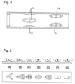
- Fig. 4
- is a cut side view of a third embodiment;
- Fig. 5A to 5G
- are side and plan views of further embodiments of protrusions;
- Fig. 6
- a cut side view of a further embodiment with a replaceable article inserted;
- Fig. 7
- a cut side view of a further embodiment similar to that of
Fig. 6 ; - Fig. 8
- a cut side view of yet another embodiment with further portions of an aerosol generation device shown; and
- Figs. 9A, 9B
- are side views of embodiments of protrusions in support of the meaning of the angle between the protrusion surface and the receptacle internal surface.
- As can be taken from
Fig. 1 , areceptacle 10 of an aerosol generation device is essentially tube-shaped and adapted to accommodate a replaceable article, such as a tobacco stick. As indicated by arrow A, air essentially flows through a tobacco stick along the receptacle axis, and will enter thereceptacle 10 at anair inlet 12 in an essentially cold state. Along the airflow path, the tobacco stick includes susceptors adapted to cooperate with one or more induction coils (not shown) around the receptacle so as to be heated and transfer the heat to the surrounding tobacco. In the embodiment shown, twoprotrusions 14 are formed at the same position along the axial direction and at diametrically opposite positions along the circumferential direction. Similar to a Venturi tube, airflow in the area of the protrusions, where the tobacco stick is correspondingly constricted, is accelerated, so that heated air can be quickly transported away from the particularly hot area surrounding the susceptors. - As can particularly be taken from
Fig. 2 , the protrusions have a smooth cross-sectional geometry, so that no undesired turbulences are created, and a tobacco stick can be inserted, sliding between the protrusions without risking damage of the tobacco stick. - This also applies to the embodiment of
Fig. 3 , which differs from that ofFig. 1 and 2 , with regard to both the shape and number of the protrusions. Firstly, the protrusions have an asymmetric shape with a steeper ascending portion, as viewed in the direction of flow, and a less steep descending portion. This particularly allows easy insertion of a tobacco stick in a direction opposite to the flow direction. Secondly, in contrast toFig. 1 and 2 , plural protrusions, for example 12 protrusions are provided equidistantly along the circumference of the receptacle. Further, transversal dimensions of the ascending portion increase with a gradient higher as seen in the flow direction, than the gradient, with which these dimensions decrease in the descending portion as can be seen in the center part ofFig. 3 , similar to a drop-shape. - As shown in
Fig. 4 , plural protrusions can also be provided at different axial positions, which can be considered a staggered arrangement. Moreover, in the embodiment shown, protrusions at different axial positions are additionally offset in circumferential direction. It goes without saying that plural protrusions can also be provided at more than two axial positions, and that the distance between protrusion positions in the circumferential direction can be the same over the entire circumference or can vary. Moreover, any arrangement of protrusions shown in the figures can be chosen with symmetric protrusions as shown inFig. 1, 2 and4 , as well as asymmetric protrusions as shown inFig. 3 , including any further shapes shown inFig. 5 . In this context, when plural protrusions are present, they can all have the same or different shapes. - As can be taken from
Fig. 5 , additional smooth and/or aerodynamic shapes, such as that of a chevron (A) arrowhead (B), asymmetric fillet combined with a chamfer as ascending portion (C) symmetric fillet (D) asymmetric fillet(E), symmetric chamfer (F) and asymmetric chamfer (D) will be suitable. Chevron and arrowhead essentially have a point at one end thereof and their shape as seen in a plan view can be described as essentially triangular. In contrast to an arrowhead, which quite well corresponds to a triangular shape in a plan view, a chevron has a cut out as seen in a plan view, on the side opposite the point. A chamfer essentially has a flat, inclined surface as seen in a cross-sectional view, and a fillet is essentially oval or elliptic, as seen in a plan view. The flow direction will typically be from right to left inFig. 5 . - As shown in particular in
Fig. 1 to 4 , one or more protrusions can be formed by thickening the receptacle wall. Alternatively, the receptacle wall can have a uniform wall thickness, and one or more protrusions can be formed as a convex shape inside the receptacle corresponding to a concave shape on the outside thereof. As can be taken particularly fromFig. 2 to 5 , each protrusion has a protrusion surface adjacent the receptacle internal surface which forms an angle α with the receptacle internal surface greater than 100°, especially in the embodiment ofFig. 2 ,4 and 5 , apart from 5B, this angle is significantly greater than 100° and remains that large along the entire protrusion as seen in an airflow direction. In other words, each protrusion lacks any surfaces extending "steep" towards the receptacle internal surface which would create unwanted turbulences. - The measurement and, respectively, determination of the angle α between the protrusion surface and the receptacle internal surface is illustrated in detail in
Figs. 9A and 9B which illustrate two different configurations of theprotrusion 14. InFig. 9A , theprotrusion 14 has a roof-like shape with a linearly ascending portion (portion comprising point A) and a linearly descending portion (portion comprising point B) along the airflow direction (indicated by the arrow). InFig. 9B , theprotrusion 14 has a semi-circular shape with an ascending portion becoming gradually shallower (portion comprising point A) and a descending portion becoming gradually steeper (portion comprising point B) along the airflow direction (indicated by the arrow). With reference toFigs. 9A and 9B , the feature that the protrusion surface forms an angle α with the receptacle internal surface which is greater than 100 degrees (100°) along theentire protrusion 14 in an airflow direction means that an angle between a straight line (tangent) at each point of the profile of theprotrusion 14 in a cross section of the protrusion along the airflow direction and the receptacle internal surface is greater than 100 degrees. InFigs. 9A and 9B , such straight line (tangent) is exemplarily shown at points A and B by the dashed lines. In the ascending portions (portions comprising points A), the angle α is measured with respect to the receptacle internal surface upstream of theprotrusion 14 with respect to the airflow direction. In the descending portions (portions comprising points B), the angle α is measured with respect to the receptacle internal surface downstream of theprotrusion 14 with respect to the airflow direction. While the angle α remains the same at each point of theprotrusion 14 in the ascending portion inFig. 9A , it changes, i.e. becomes greater, when going along the airflow direction in the ascending portion of theprotrusion 14 shown inFig. 9B . -
Fig. 6 shows areceptacle 10 with twodiametrically protrusions 14 similar to those ofFig. 5D or F .Fig. 6 additionally shows areplaceable article 16, such as a tobacco stick accommodated in thereceptacle 10 and correspondingly compressed in the area of theprotrusions 14. This compression, firstly, moves thetobacco strands 18 closer together in the area of theprotrusions 14 and, secondly, bendssusceptors 20 accommodated in thereplaceable article 16. Thesesusceptors 20 may have a curved, convex shape already in the original state, i.e. without being compressed by theprotrusions 14. In particular, the convex shapes of two or more susceptors can face each other towards the center of thereplaceable article 16. Alternatively or additionally, the convex shape shown in the figure can be caused by the compression in the area of the protrusions. 14. - In any case, as is better illustrated in
Fig. 7 , the cross-sectional area of thereplaceable article 16 is smaller in the area of theprotrusions 14, so that the flow velocity is increased, and heat is transported at a higher rate than in the area of the inlet and the outlet of the replaceable article shown. Whereas the location of the susceptors, which are typically thin strands of material heatable by a surrounding coil (not shown), can correspond to that of theprotrusions 14 and can be essentially symmetrical thereto, as shown inFig. 6 , the susceptors can also be somewhat shifted towards theinlet 12. In the embodiment shown inFig. 7 , the inlet end of each susceptor is somewhat closer to theinlet 12 of thereceptacle 10 than the inlet end of eachprotrusion 14, and the susceptors cover about two thirds of the longitudinal extension of the protrusions. As mentioned, in the embodiment ofFig. 6 , the location of thesusceptors 20 is symmetrical to that of theprotrusion 14, and their inlet end is somewhat more remote from theinlet 12 of the receptacle than the inlet end of theprotrusions 14, and their outlet end is somewhat more remote from the outlet of the receptacle than the outlet end of theprotrusions 14. - Moreover, as indicated in
Fig. 7 , due to the asymmetrical position of the susceptors, these are closer together towards their outlet end, than at their inlet end. - The above-described effect of compressing the
replaceable article 16 in order to quickly remove heat from particularly hot areas is also achieved by the embodiment ofFig. 8 , in which protrusions 14 are provided at the outlet end of the receptacle and are formed as heating elements. In other words, unlike the previously described embodiments, thereplaceable article 16 is not heated from within, such as by means of thesusceptors 20, but from the receptacle walls. The principle underlying the invention, i.e. providing protrusions so as to compress or constrict the airflow path remains the same. It should also be mentioned, that susceptors could be located in an area corresponding to theprotrusions 14 shown inFig. 8 , when induction heating is used instead of external heating as in the embodiment ofFig. 8 . For the sake of completeness,Fig. 8 also shows, downstream the outlet end of thereceptacle 10, asupport 22 having anairpath 24, as well as, downstream of thesupport 22, afilter 26. - The following itemized paragraphs also form part of the present disclosure.
- Item 1. An aerosol generation device configured to operate with a replaceable article (16) comprising a storage compartment containing a vaporizable material, the storage compartment defining an airflow path extending between an air inlet (12) and an air outlet through the vaporizable material;
- the aerosol generation device comprising:
- a receptacle (10) extending along a receptacle axis (A), defining a receptacle internal surface and configured to receive the replaceable article (16) in a space delimited by the receptacle internal surface so as the airflow path extends along the receptacle axis (A);
- a heating system configured to heat the replaceable article (16) when it is received in the receptacle (10);
- the aerosol generation device being characterized in that the receptacle internal surface comprises at least one protrusion (14) protruding from the receptacle internal surface and configured to reduce the cross-sectional area of the receptacle so as to compress a part of the airflow path of the storage compartment, when the replaceable article (16) is received in the receptacle (10);
- the or each protrusion (14) defining a protrusion surface adjacent to the receptacle internal surface and forming an angle with the receptacle internal surface greater than 100° along the entire protrusion (14) in an airflow direction.
- Item 2. The aerosol generation device according to item 1, wherein the maximum height of the or each protrusion (14) measured according to an axis perpendicular to the receptacle axis (A) is comprised between 2% and 15% of the receptacle diameter, and preferably between 5% and 10% of said diameter.
- Item 3. The aerosol generation device according to item 1 or 2, wherein the maximum length of the or each protrusion (14) measured according to the receptacle axis (A) is comprised between 5% and 75% of the receptacle length measured according to the receptacle axis (A), and preferably between 10% and 65% of said length.
- Item 4. The aerosol generation device according to any one of the preceding items, wherein the or each protrusion (14) forms an ascending portion, a top portion and a descending portion;
the ascending portion extends from the receptacle internal surface until the top portion and the descending portion extends from the top portion until the receptacle internal surface. - Item 5. The aerosol generation device according to item 4, wherein the ascending portion is symmetric to the descending portion with respect to the top portion.
- Item 6. The aerosol generation device according to item 4 or 5, wherein the ascending portion defines transversal dimensions gradually increasing from the receptacle internal surface until the top portion, and/or the descending portion defines transversal dimensions gradually decreasing from the top portion until the receptacle internal surface.
- Item 7. The aerosol generation device according to any one of the preceding items, wherein the shape of the or each protrusion (14) is chosen in the group consisting of:
- chevron;
- arrowhead;
- asymmetric fillet and chamfer;
- symmetric fillet;
- asymmetric fillet;
- symmetric chamfer;
- asymmetric chamfer.
- Item 8. The aerosol generation device according to any one of the preceding items, comprising a plurality of protrusions (14) arranged on the receptacle internal surface axially according to the receptacle axis (A) and/or circumferentially.
- Item 9. The aerosol generation device according to any one of the preceding items, wherein the or each protrusion (14) is arranged to be adjacent to the air outlet of the storage compartment, when the replaceable article (16) is received in the receptacle (10).
-
Item 10. The aerosol generation device according to any one of the preceding items, wherein the or each protrusion (14) is moveable according to the receptacle axis (A). - Item 11. The aerosol generation device according to any one of the preceding items, wherein the or each protrusion (14) is moveable according to an axis perpendicular to the receptacle axis (A) between an engaged position and a disengaged position;
the replaceable article (16) being freely moveable within the receptacle (10) according to the receptacle axis (A) when the or each protrusion (14) is in the disengaged position and being locked in the receptacle (10) when the or each protrusion (14) is in the engaged position. -
Item 12. The aerosol generation device according to any one of the preceding items, wherein the heating system is an inductive heating system comprising a coil configured to create a magnetic field, the storage compartment of the replaceable article (16) comprising at least one susceptor (20) extending along the airflow path between an upstream end and a downstream end, and being able to generate heat when it is placed in the magnetic field created by the coil; - the or each protrusion (14) is arranged to face at least partially a susceptor (20) of the storage compartment of the replaceable article (16), when the replaceable article (16) is received in the receptacle (10);
- preferably, the number of protrusions (14) being chosen equal to the number of the susceptors (20).
- Item 13. The aerosol generation device according to
item 12, wherein the or each protrusion (14) defines a top portion arranged to face the downstream end of the corresponding susceptor (20), when the replaceable article (16) is received in the receptacle (10). -
Item 14. The aerosol generation device according to any one of items 1 to 11, wherein the heating system comprises one or several heating elements extending along at least a part of the receptacle internal surface and the contact surface of the or each protrusion (14). - Item 15. An aerosol generation set comprising:
- a replaceable article (16) comprising a storage compartment containing a vaporizable material, the storage compartment defining an airflow path extending between an air inlet (12) and an air outlet through the vaporizable material;
- an aerosol generation device according to any one of the preceding items, configured to operate with the replaceable article (16).
Claims (17)
- An aerosol generation device configured to operate with a replaceable article (16) comprising a storage compartment containing a vaporizable material, the storage compartment defining an airflow path extending between an air inlet (12) and an air outlet through the vaporizable material;the aerosol generation device comprising:- a receptacle (10) extending along a receptacle axis (A), defining a receptacle internal surface and configured to receive the replaceable article (16) in a space delimited by the receptacle internal surface so as the airflow path extends along the receptacle axis (A);- a heating system configured to heat the replaceable article (16) when it is received in the receptacle (10);the aerosol generation device being characterized in that the receptacle internal surface comprises one protrusion (14) or a plurality of protrusions (14) protruding from the receptacle internal surface and configured to reduce the cross-sectional area of the receptacle, wherein the maximum height of the protrusion (14) or each protrusion (14) of the plurality of protrusions (14) measured according to an axis perpendicular to the receptacle axis (A) is comprised between 2% and 15% of the receptacle diameter;the protrusion (14) or each protrusion (14) of the plurality of protrusions (14) defining a protrusion surface adjacent to the receptacle internal surface and forming an angle with the receptacle internal surface greater than 100° along the entire protrusion (14) in an airflow direction,wherein the protrusion (14) or each protrusion of the plurality of protrusions (14) is provided on the receptacle internal surface in a fixed manner.
- The aerosol generation device according to claim 1, wherein the maximum height of the protrusion (14) or each protrusion (14) of the plurality of protrusions (14) measured according to an axis perpendicular to the receptacle axis (A) is comprised between 5% and 10% of the receptacle diameter.
- The aerosol generation device according to claim 1 or 2, wherein the maximum length of the protrusion (14) or each protrusion (14) of the plurality of protrusions (14) measured according to the receptacle axis (A) is comprised between 5% and 75% of the receptacle length measured according to the receptacle axis (A), and preferably between 10% and 65% of said length.
- The aerosol generation device according to any one of the preceding claims, wherein the protrusion (14) or each protrusion (14) of the plurality of protrusions (14) forms an ascending portion, a top portion and a descending portion;
the ascending portion extends from the receptacle internal surface until the top portion and the descending portion extends from the top portion until the receptacle internal surface. - The aerosol generation device according to claim 4, wherein the ascending portion is symmetric or asymmetric to the descending portion with respect to the top portion.
- The aerosol generation device according to claim 4 or 5, wherein the ascending portion defines transversal dimensions gradually increasing from the receptacle internal surface until the top portion, and/or the descending portion defines transversal dimensions gradually decreasing from the top portion until the receptacle internal surface.
- The aerosol generation device according to any one of the preceding claims, wherein the shape of the protrusion (14) or each protrusion (14) of the plurality of protrusions (14) is chosen in the group consisting of:- chevron;- arrowhead;- asymmetric fillet and chamfer;- symmetric fillet;- asymmetric fillet;- symmetric chamfer;- asymmetric chamfer.
- The aerosol generation device according to any one of the preceding claims, comprising the plurality of protrusions (14) arranged on the receptacle internal surface axially according to the receptacle axis (A) and/or circumferentially.
- The aerosol generation device according to any one of the preceding claims, wherein the protrusion (14) or each protrusion (14) of the plurality of protrusions (14) is arranged to be adjacent to the air outlet of the storage compartment, when the replaceable article (16) is received in the receptacle (10).
- The aerosol generation device according to any one of the preceding claims, wherein the heating system is an inductive heating system comprising a coil configured to create a magnetic field, the storage compartment of the replaceable article (16) comprising at least one susceptor (20) extending along the airflow path between an upstream end and a downstream end, and being able to generate heat when it is placed in the magnetic field created by the coil;
the protrusion (14) or each protrusion (14) of the plurality of protrusions (14) is arranged to face at least partially a susceptor (20) of the storage compartment of the replaceable article (16), when the replaceable article (16) is received in the receptacle (10). - The aerosol generation device according to claim 10, wherein the protrusion (14) or each protrusion (14) of the plurality of protrusions (14) defines a top portion arranged to face the downstream end of the corresponding susceptor (20), when the replaceable article (16) is received in the receptacle (10).
- The aerosol generation device according to any one of the preceding claims, wherein the protrusion (14) or the plurality of protrusions (14) protruding from the receptacle internal surface is configured to reduce the cross-sectional area of the receptacle so as to compress a part of the airflow path of the storage compartment, when the replaceable article (16) is received in the receptacle (10).
- The aerosol generation device according to any one of the preceding claims, comprising the plurality of protrusions (14) having the same or different shapes.
- The aerosol generation device according to any one of the preceding claims, wherein the angle at a point where the protrusion emerges from the receptacle internal surface is between 100 and 175 degrees, preferably between 130 and 170 degrees, as seen in a longitudinal cut view.
- The aerosol generation device according to any one of the preceding claims, wherein the protrusion (14) or each protrusion (14) of the plurality of protrusions (14) is provided at an outlet end of the receptacle, as seen in the airflow direction.
- The aerosol generation device according to any one of the preceding claims, wherein the protrusion (14) or each protrusion of the plurality of protrusions (14) is provided on the receptacle internal surface integrally with the receptacle wall.
- An aerosol generation set comprising:- a replaceable article (16) comprising a storage compartment containing a vaporizable material, the storage compartment defining an airflow path extending between an air inlet (12) and an air outlet through the vaporizable material;- an aerosol generation device according to any one of the preceding claims, configured to operate with the replaceable article (16).
Applications Claiming Priority (3)
| Application Number | Priority Date | Filing Date | Title |
|---|---|---|---|
| EP21173010 | 2021-05-10 | ||
| PCT/EP2022/062427 WO2022238295A1 (en) | 2021-05-10 | 2022-05-09 | Aerosol generation device and set |
| EP22728194.6A EP4337043B1 (en) | 2021-05-10 | 2022-05-09 | Aerosol generation device |
Related Parent Applications (1)
| Application Number | Title | Priority Date | Filing Date |
|---|---|---|---|
| EP22728194.6A Division EP4337043B1 (en) | 2021-05-10 | 2022-05-09 | Aerosol generation device |
Publications (2)
| Publication Number | Publication Date |
|---|---|
| EP4545123A2 true EP4545123A2 (en) | 2025-04-30 |
| EP4545123A3 EP4545123A3 (en) | 2025-06-11 |
Family
ID=75887899
Family Applications (2)
| Application Number | Title | Priority Date | Filing Date |
|---|---|---|---|
| EP25157889.4A Pending EP4545123A3 (en) | 2021-05-10 | 2022-05-09 | Aerosol generation device and set |
| EP22728194.6A Active EP4337043B1 (en) | 2021-05-10 | 2022-05-09 | Aerosol generation device |
Family Applications After (1)
| Application Number | Title | Priority Date | Filing Date |
|---|---|---|---|
| EP22728194.6A Active EP4337043B1 (en) | 2021-05-10 | 2022-05-09 | Aerosol generation device |
Country Status (9)
| Country | Link |
|---|---|
| US (1) | US20240237744A1 (en) |
| EP (2) | EP4545123A3 (en) |
| JP (1) | JP2024517062A (en) |
| KR (1) | KR20240006522A (en) |
| CN (1) | CN117320571A (en) |
| ES (1) | ES3027367T3 (en) |
| HU (1) | HUE070971T2 (en) |
| PL (1) | PL4337043T3 (en) |
| WO (1) | WO2022238295A1 (en) |
Family Cites Families (18)
| Publication number | Priority date | Publication date | Assignee | Title |
|---|---|---|---|---|
| US5505214A (en) | 1991-03-11 | 1996-04-09 | Philip Morris Incorporated | Electrical smoking article and method for making same |
| CN103997922B (en) * | 2011-11-21 | 2016-12-14 | 菲利普莫里斯生产公司 | Extractors for aerosol generating devices |
| CN203563687U (en) | 2013-11-05 | 2014-04-30 | 湖北中烟工业有限责任公司 | Heat conduction type low-temperature cigarette heat preservation sleeve |
| TWI666993B (en) | 2014-05-21 | 2019-08-01 | Philip Morris Products S. A. | Inductive heating device and system for aerosol generation |
| US20170055580A1 (en) | 2015-08-31 | 2017-03-02 | British American Tobacco (Investments) Limited | Apparatus for heating smokable material |
| AR109120A1 (en) | 2016-07-26 | 2018-10-31 | British American Tobacco Investments Ltd | APPARATUS FOR HEATING FUMABLE MATERIAL |
| PL3512363T3 (en) | 2016-09-15 | 2022-10-10 | Philip Morris Products S.A. | Aerosol-generating device |
| KR20180070451A (en) | 2016-12-16 | 2018-06-26 | 주식회사 케이티앤지 | Heater and system for heating an aerosol generating substrate |
| RU2749137C2 (en) * | 2016-12-16 | 2021-06-04 | Кей Ти Энд Джи Корпорейшн | Device and method for aerosol generation |
| US11197497B2 (en) | 2017-04-11 | 2021-12-14 | Kt&G Corporation | Aerosol generating device |
| KR102412630B1 (en) * | 2017-09-07 | 2022-06-23 | 주식회사 케이티앤지 | Aerosol generating apparatus |
| CN119014593A (en) | 2018-01-22 | 2024-11-26 | 上海新型烟草制品研究院有限公司 | Release mechanism and aerosol generating device |
| CN207821113U (en) | 2018-01-31 | 2018-09-07 | 湖北中烟工业有限责任公司 | Take the electric heater unit that can prevent tobacco from falling off when cigarette |
| EP4344566A3 (en) * | 2018-10-12 | 2024-07-03 | JT International SA | Aerosol generation device and heating chamber therefor |
| TWI739172B (en) | 2018-10-12 | 2021-09-11 | 瑞士商傑太日煙國際股份有限公司(瑞士) | Aerosol generation device, and heating chamber therefor, and aerosol generation system |
| KR102718033B1 (en) | 2019-08-28 | 2024-10-17 | 필립모리스 프로덕츠 에스.에이. | Flare-type susceptor heating array for aerosol generating devices |
| TWI779347B (en) | 2019-09-06 | 2022-10-01 | 瑞士商傑太日煙國際股份有限公司(瑞士) | Aerosol generation device and heating chamber therefor |
| EP4076054B1 (en) | 2019-12-17 | 2024-05-15 | Philip Morris Products S.A. | Aerosol-generating device comprising a chamber for receiving an aerosol-generating article |
-
2022
- 2022-05-09 CN CN202280032178.7A patent/CN117320571A/en active Pending
- 2022-05-09 HU HUE22728194A patent/HUE070971T2/en unknown
- 2022-05-09 PL PL22728194.6T patent/PL4337043T3/en unknown
- 2022-05-09 KR KR1020237037051A patent/KR20240006522A/en active Pending
- 2022-05-09 US US18/559,885 patent/US20240237744A1/en active Pending
- 2022-05-09 WO PCT/EP2022/062427 patent/WO2022238295A1/en not_active Ceased
- 2022-05-09 EP EP25157889.4A patent/EP4545123A3/en active Pending
- 2022-05-09 JP JP2023559763A patent/JP2024517062A/en active Pending
- 2022-05-09 ES ES22728194T patent/ES3027367T3/en active Active
- 2022-05-09 EP EP22728194.6A patent/EP4337043B1/en active Active
Also Published As
| Publication number | Publication date |
|---|---|
| HUE070971T2 (en) | 2025-07-28 |
| PL4337043T3 (en) | 2025-06-16 |
| EP4337043B1 (en) | 2025-02-19 |
| US20240237744A1 (en) | 2024-07-18 |
| EP4337043C0 (en) | 2025-02-19 |
| CN117320571A (en) | 2023-12-29 |
| KR20240006522A (en) | 2024-01-15 |
| ES3027367T3 (en) | 2025-06-13 |
| WO2022238295A1 (en) | 2022-11-17 |
| EP4337043A1 (en) | 2024-03-20 |
| EP4545123A3 (en) | 2025-06-11 |
| JP2024517062A (en) | 2024-04-19 |
Similar Documents
| Publication | Publication Date | Title |
|---|---|---|
| JP7736775B2 (en) | Aerosol-generating article, method for manufacturing an aerosol-generating article, and aerosol-generating system | |
| US8028744B2 (en) | Heat sink system and assembly | |
| US20220364672A1 (en) | Multiple Geometry And Multiple Material Insulated Components | |
| US20100139631A1 (en) | Heat exchanger | |
| EP0091127A1 (en) | Helicoidally finned tubes | |
| KR101892572B1 (en) | Metallic Heat Transfer Tube | |
| CN110274504A (en) | Heat exchanger fin | |
| SA94150259B1 (en) | Slotted tubes for heat exchangers in air conditioning and refrigeration equipment and corresponding exchangers | |
| US20240237744A1 (en) | Aerosol Generation Device and Set | |
| CN101881571A (en) | Finned tube heat exchanger | |
| US20150047820A1 (en) | Bendable heat exchanger | |
| KR20170012149A (en) | Heat exchanger tube and heating boiler having such a heat exchanger tube | |
| CN107091390A (en) | Bend pipe structure, pipeline and straight tube structure | |
| KR20010007189A (en) | Turbine device | |
| US11525618B2 (en) | Enhanced heat exchanger performance under frosting conditions | |
| EA048253B1 (en) | AEROSOL GENERATING DEVICE AND KIT | |
| JP2022535394A5 (en) | ||
| US20110186563A1 (en) | Electric heater with omega tube | |
| US4352659A (en) | Method of heating an end of a length of plastic pipe and a circulating air furnace for carrying out the method | |
| EP4364595A1 (en) | Aerosol generating devices and induction heating assemblies therefor | |
| JP2024517062A5 (en) | ||
| ITMI20091740A1 (en) | AXIAL STEAM TURBINE POWERED HIGH TEMPERATURE RADIAL | |
| CN221882293U (en) | A heat exchange tube suitable for circumferential arrangement | |
| CN108700386B (en) | Heat exchanger and method of operating a heat exchanger | |
| Hashizume et al. | Fin efficiency of serrated fins: Part 1. Analysis of theoretical fin efficiency and experimental results |
Legal Events
| Date | Code | Title | Description |
|---|---|---|---|
| PUAI | Public reference made under article 153(3) epc to a published international application that has entered the european phase |
Free format text: ORIGINAL CODE: 0009012 |
|
| STAA | Information on the status of an ep patent application or granted ep patent |
Free format text: STATUS: REQUEST FOR EXAMINATION WAS MADE |
|
| 17P | Request for examination filed |
Effective date: 20250214 |
|
| AC | Divisional application: reference to earlier application |
Ref document number: 4337043 Country of ref document: EP Kind code of ref document: P |
|
| AK | Designated contracting states |
Kind code of ref document: A2 Designated state(s): AL AT BE BG CH CY CZ DE DK EE ES FI FR GB GR HR HU IE IS IT LI LT LU LV MC MK MT NL NO PL PT RO RS SE SI SK SM TR |
|
| REG | Reference to a national code |
Ref country code: DE Ref legal event code: R079 Free format text: PREVIOUS MAIN CLASS: A61M0015060000 Ipc: A24F0040400000 |
|
| PUAL | Search report despatched |
Free format text: ORIGINAL CODE: 0009013 |
|
| AK | Designated contracting states |
Kind code of ref document: A3 Designated state(s): AL AT BE BG CH CY CZ DE DK EE ES FI FR GB GR HR HU IE IS IT LI LT LU LV MC MK MT NL NO PL PT RO RS SE SI SK SM TR |
|
| RIC1 | Information provided on ipc code assigned before grant |
Ipc: A61M 15/06 20060101ALI20250507BHEP Ipc: A24F 40/465 20200101ALI20250507BHEP Ipc: A24F 40/40 20200101AFI20250507BHEP |