EP4544981A2 - Articulation locking mechanisms for end effectors - Google Patents
Articulation locking mechanisms for end effectors Download PDFInfo
- Publication number
- EP4544981A2 EP4544981A2 EP25162524.0A EP25162524A EP4544981A2 EP 4544981 A2 EP4544981 A2 EP 4544981A2 EP 25162524 A EP25162524 A EP 25162524A EP 4544981 A2 EP4544981 A2 EP 4544981A2
- Authority
- EP
- European Patent Office
- Prior art keywords
- end effector
- catheter
- medical device
- pivot arm
- opening
- Prior art date
- Legal status (The legal status is an assumption and is not a legal conclusion. Google has not performed a legal analysis and makes no representation as to the accuracy of the status listed.)
- Pending
Links
Images




Classifications
-
- A—HUMAN NECESSITIES
- A61—MEDICAL OR VETERINARY SCIENCE; HYGIENE
- A61B—DIAGNOSIS; SURGERY; IDENTIFICATION
- A61B17/00—Surgical instruments, devices or methods
- A61B17/068—Surgical staplers, e.g. containing multiple staples or clamps
- A61B17/072—Surgical staplers, e.g. containing multiple staples or clamps for applying a row of staples in a single action, e.g. the staples being applied simultaneously
- A61B17/07207—Surgical staplers, e.g. containing multiple staples or clamps for applying a row of staples in a single action, e.g. the staples being applied simultaneously the staples being applied sequentially
-
- A—HUMAN NECESSITIES
- A61—MEDICAL OR VETERINARY SCIENCE; HYGIENE
- A61B—DIAGNOSIS; SURGERY; IDENTIFICATION
- A61B17/00—Surgical instruments, devices or methods
- A61B17/28—Surgical forceps
- A61B17/29—Forceps for use in minimally invasive surgery
-
- A—HUMAN NECESSITIES
- A61—MEDICAL OR VETERINARY SCIENCE; HYGIENE
- A61B—DIAGNOSIS; SURGERY; IDENTIFICATION
- A61B17/00—Surgical instruments, devices or methods
- A61B17/28—Surgical forceps
- A61B17/29—Forceps for use in minimally invasive surgery
- A61B17/2909—Handles
-
- A—HUMAN NECESSITIES
- A61—MEDICAL OR VETERINARY SCIENCE; HYGIENE
- A61B—DIAGNOSIS; SURGERY; IDENTIFICATION
- A61B1/00—Instruments for performing medical examinations of the interior of cavities or tubes of the body by visual or photographical inspection, e.g. endoscopes; Illuminating arrangements therefor
- A61B1/012—Instruments for performing medical examinations of the interior of cavities or tubes of the body by visual or photographical inspection, e.g. endoscopes; Illuminating arrangements therefor characterised by internal passages or accessories therefor
-
- A—HUMAN NECESSITIES
- A61—MEDICAL OR VETERINARY SCIENCE; HYGIENE
- A61B—DIAGNOSIS; SURGERY; IDENTIFICATION
- A61B1/00—Instruments for performing medical examinations of the interior of cavities or tubes of the body by visual or photographical inspection, e.g. endoscopes; Illuminating arrangements therefor
- A61B1/313—Instruments for performing medical examinations of the interior of cavities or tubes of the body by visual or photographical inspection, e.g. endoscopes; Illuminating arrangements therefor for introducing through surgical openings, e.g. laparoscopes
- A61B1/3132—Instruments for performing medical examinations of the interior of cavities or tubes of the body by visual or photographical inspection, e.g. endoscopes; Illuminating arrangements therefor for introducing through surgical openings, e.g. laparoscopes for laparoscopy
-
- A—HUMAN NECESSITIES
- A61—MEDICAL OR VETERINARY SCIENCE; HYGIENE
- A61B—DIAGNOSIS; SURGERY; IDENTIFICATION
- A61B17/00—Surgical instruments, devices or methods
- A61B17/00234—Surgical instruments, devices or methods for minimally invasive surgery
- A61B2017/00292—Surgical instruments, devices or methods for minimally invasive surgery mounted on or guided by flexible, e.g. catheter-like, means
- A61B2017/00296—Surgical instruments, devices or methods for minimally invasive surgery mounted on or guided by flexible, e.g. catheter-like, means mounted on an endoscope
-
- A—HUMAN NECESSITIES
- A61—MEDICAL OR VETERINARY SCIENCE; HYGIENE
- A61B—DIAGNOSIS; SURGERY; IDENTIFICATION
- A61B17/00—Surgical instruments, devices or methods
- A61B17/00234—Surgical instruments, devices or methods for minimally invasive surgery
- A61B2017/00292—Surgical instruments, devices or methods for minimally invasive surgery mounted on or guided by flexible, e.g. catheter-like, means
- A61B2017/003—Steerable
-
- A—HUMAN NECESSITIES
- A61—MEDICAL OR VETERINARY SCIENCE; HYGIENE
- A61B—DIAGNOSIS; SURGERY; IDENTIFICATION
- A61B17/00—Surgical instruments, devices or methods
- A61B17/00234—Surgical instruments, devices or methods for minimally invasive surgery
- A61B2017/00292—Surgical instruments, devices or methods for minimally invasive surgery mounted on or guided by flexible, e.g. catheter-like, means
- A61B2017/0034—Surgical instruments, devices or methods for minimally invasive surgery mounted on or guided by flexible, e.g. catheter-like, means adapted to be inserted through a working channel of an endoscope
-
- A—HUMAN NECESSITIES
- A61—MEDICAL OR VETERINARY SCIENCE; HYGIENE
- A61B—DIAGNOSIS; SURGERY; IDENTIFICATION
- A61B17/00—Surgical instruments, devices or methods
- A61B2017/00367—Details of actuation of instruments, e.g. relations between pushing buttons, or the like, and activation of the tool, working tip, or the like
-
- A—HUMAN NECESSITIES
- A61—MEDICAL OR VETERINARY SCIENCE; HYGIENE
- A61B—DIAGNOSIS; SURGERY; IDENTIFICATION
- A61B17/00—Surgical instruments, devices or methods
- A61B2017/0046—Surgical instruments, devices or methods with a releasable handle; with handle and operating part separable
-
- A—HUMAN NECESSITIES
- A61—MEDICAL OR VETERINARY SCIENCE; HYGIENE
- A61B—DIAGNOSIS; SURGERY; IDENTIFICATION
- A61B17/00—Surgical instruments, devices or methods
- A61B17/068—Surgical staplers, e.g. containing multiple staples or clamps
- A61B17/072—Surgical staplers, e.g. containing multiple staples or clamps for applying a row of staples in a single action, e.g. the staples being applied simultaneously
- A61B2017/07214—Stapler heads
-
- A—HUMAN NECESSITIES
- A61—MEDICAL OR VETERINARY SCIENCE; HYGIENE
- A61B—DIAGNOSIS; SURGERY; IDENTIFICATION
- A61B17/00—Surgical instruments, devices or methods
- A61B17/068—Surgical staplers, e.g. containing multiple staples or clamps
- A61B17/072—Surgical staplers, e.g. containing multiple staples or clamps for applying a row of staples in a single action, e.g. the staples being applied simultaneously
- A61B2017/07214—Stapler heads
- A61B2017/07257—Stapler heads characterised by its anvil
-
- A—HUMAN NECESSITIES
- A61—MEDICAL OR VETERINARY SCIENCE; HYGIENE
- A61B—DIAGNOSIS; SURGERY; IDENTIFICATION
- A61B17/00—Surgical instruments, devices or methods
- A61B17/068—Surgical staplers, e.g. containing multiple staples or clamps
- A61B17/072—Surgical staplers, e.g. containing multiple staples or clamps for applying a row of staples in a single action, e.g. the staples being applied simultaneously
- A61B2017/07214—Stapler heads
- A61B2017/07271—Stapler heads characterised by its cartridge
-
- A—HUMAN NECESSITIES
- A61—MEDICAL OR VETERINARY SCIENCE; HYGIENE
- A61B—DIAGNOSIS; SURGERY; IDENTIFICATION
- A61B17/00—Surgical instruments, devices or methods
- A61B17/068—Surgical staplers, e.g. containing multiple staples or clamps
- A61B17/072—Surgical staplers, e.g. containing multiple staples or clamps for applying a row of staples in a single action, e.g. the staples being applied simultaneously
- A61B2017/07214—Stapler heads
- A61B2017/07278—Stapler heads characterised by its sled or its staple holder
-
- A—HUMAN NECESSITIES
- A61—MEDICAL OR VETERINARY SCIENCE; HYGIENE
- A61B—DIAGNOSIS; SURGERY; IDENTIFICATION
- A61B17/00—Surgical instruments, devices or methods
- A61B17/068—Surgical staplers, e.g. containing multiple staples or clamps
- A61B17/072—Surgical staplers, e.g. containing multiple staples or clamps for applying a row of staples in a single action, e.g. the staples being applied simultaneously
- A61B2017/07214—Stapler heads
- A61B2017/07285—Stapler heads characterised by its cutter
-
- A—HUMAN NECESSITIES
- A61—MEDICAL OR VETERINARY SCIENCE; HYGIENE
- A61B—DIAGNOSIS; SURGERY; IDENTIFICATION
- A61B17/00—Surgical instruments, devices or methods
- A61B17/28—Surgical forceps
- A61B17/29—Forceps for use in minimally invasive surgery
- A61B2017/2926—Details of heads or jaws
- A61B2017/2927—Details of heads or jaws the angular position of the head being adjustable with respect to the shaft
-
- A—HUMAN NECESSITIES
- A61—MEDICAL OR VETERINARY SCIENCE; HYGIENE
- A61B—DIAGNOSIS; SURGERY; IDENTIFICATION
- A61B17/00—Surgical instruments, devices or methods
- A61B17/28—Surgical forceps
- A61B17/29—Forceps for use in minimally invasive surgery
- A61B2017/2926—Details of heads or jaws
- A61B2017/2927—Details of heads or jaws the angular position of the head being adjustable with respect to the shaft
- A61B2017/2929—Details of heads or jaws the angular position of the head being adjustable with respect to the shaft with a head rotatable about the longitudinal axis of the shaft
- A61B2017/293—Details of heads or jaws the angular position of the head being adjustable with respect to the shaft with a head rotatable about the longitudinal axis of the shaft with means preventing relative rotation between the shaft and the actuating rod
-
- A—HUMAN NECESSITIES
- A61—MEDICAL OR VETERINARY SCIENCE; HYGIENE
- A61B—DIAGNOSIS; SURGERY; IDENTIFICATION
- A61B17/00—Surgical instruments, devices or methods
- A61B17/28—Surgical forceps
- A61B17/29—Forceps for use in minimally invasive surgery
- A61B2017/2926—Details of heads or jaws
- A61B2017/2932—Transmission of forces to jaw members
- A61B2017/2933—Transmission of forces to jaw members camming or guiding means
- A61B2017/2936—Pins in guiding slots
-
- A—HUMAN NECESSITIES
- A61—MEDICAL OR VETERINARY SCIENCE; HYGIENE
- A61B—DIAGNOSIS; SURGERY; IDENTIFICATION
- A61B17/00—Surgical instruments, devices or methods
- A61B17/28—Surgical forceps
- A61B17/29—Forceps for use in minimally invasive surgery
- A61B2017/2926—Details of heads or jaws
- A61B2017/2932—Transmission of forces to jaw members
- A61B2017/2939—Details of linkages or pivot points
-
- A—HUMAN NECESSITIES
- A61—MEDICAL OR VETERINARY SCIENCE; HYGIENE
- A61B—DIAGNOSIS; SURGERY; IDENTIFICATION
- A61B17/00—Surgical instruments, devices or methods
- A61B17/28—Surgical forceps
- A61B17/29—Forceps for use in minimally invasive surgery
- A61B2017/2926—Details of heads or jaws
- A61B2017/2932—Transmission of forces to jaw members
- A61B2017/2944—Translation of jaw members
-
- A—HUMAN NECESSITIES
- A61—MEDICAL OR VETERINARY SCIENCE; HYGIENE
- A61B—DIAGNOSIS; SURGERY; IDENTIFICATION
- A61B17/00—Surgical instruments, devices or methods
- A61B17/28—Surgical forceps
- A61B17/29—Forceps for use in minimally invasive surgery
- A61B2017/2946—Locking means
Definitions
- This disclosure relates to minimally invasive (e.g., endoscopic and/or laparoscopic) medical devices and related methods of use.
- the disclosure relates to one or more locking mechanisms for end effectors, e.g., tissue fastening devices such as stapler devices, and related methods of use, among other aspects.
- the grasping and/or coupling of tissue in a patient's body may be performed by surgical devices that grasp or clamp tissue between opposing jaw structures and then fasten or cut the tissue.
- a drawback of these systems may include, for example, maintaining a desired orientation of the jaws of an end effector during a procedure, such as a stapling procedure, a cutting procedure, and/or additional medical procedures.
- an end effector may be articulated about a pivot point.
- actuation of the cutting and/or fastening device may cause the end effector to pivot from the selected orientation to a different, undesired orientation.
- tissue may not be properly stapled and/or cut, which may increase therapy time and/or cost, may cause undesired or incomplete fastening of tissues, and/or may require additional therapy/intervention at the target site.
- a medical device includes an end effector at a distal end of the medical device, an actuator coupled to a proximal end of the end effector, a pivot arm pivotally coupled to the end effector distal of the proximal end of the end effector, where actuation of the actuator pivots the end effector relative to the pivot arm, and a lock on the end effector and the pivot arm, where the lock has a first state permitting the end effector to pivot relative to the pivot arm and a second state restricting the end effector from pivoting relative to the pivot arm.
- the end effector may include a first jaw, and a second jaw hingedly connected to the first jaw and configured to move between an open position and a closed position.
- the locking mechanism may include a plurality of teeth at a distal end of the pivot arm, wherein the plurality of teeth may define a plurality of spaces, and a tab connected to the end effector, wherein the tab may be configured to engage a space from the plurality of spaces in the second state.
- the lock is in the first state when the pair of jaws is in the open position, and the lock is in the second state when the pair of jaws is in the closed position.
- the end effector may be configured to pivot independently of a movement of the first jaw relative to the second jaw.
- the locking mechanism may include a sprocket connected to the pivot arm, wherein the sprocket may include a plurality of teeth defining a plurality of spaces, and a pawl pivotally connected at the proximal end of the end effector and may be configured to engage the plurality of spaces.
- the medical device may further comprise a wire connected to the pawl and extending in a proximal direction, wherein the pawl may be biased into engagement with the plurality of spaces of the sprocket, and wherein moving the wire in the proximal direction may be configured to pivot the pawl away from the sprocket to disengage the pawl from the plurality of spaces.
- the sprocket may be arc shaped, and wherein a convex arrangement of the plurality of spaces of the sprocket may face proximally.
- the locking mechanism may include a ball-nose spring plunger.
- the ball-nose spring plunger may include a spring coupled at a first end of the end effector, wherein the spring may be configured to extend from the first end and compress along a compression axis, a plurality of detents fixed to the pivot arm, and a ball bearing connected to the spring and selectively engaging each of the plurality of detents, wherein the ball bearing may be configured to move along the compression axis.
- the ball bearing may be configured to move from a first detent of the plurality of detents to an adjacent, second detent of the plurality of detents as the end effector pivots about the pivot arm and wherein the spring may be configured to be compressed from a first position to a second position and expand back to the first position as the ball bearing moves from the first detent to the second detent.
- the medical device may further comprise an actuation wire fixed to a proximal end of the end effector, wherein actuation of the actuation wire may be configured to move the end effector between an open position and a closed position.
- the pivot arm may include a first opening at a proximal end of the pivot arm, a second opening in a sidewall of the pivot arm, and a lumen extending from the first opening to the second opening.
- the actuator may be configured to extend through each of the first opening, the lumen, and the second opening.
- the medical device may further comprise a handle assembly configured to actuate the end effector and the locking mechanism, wherein a proximal end of the actuator may be connected to a distal end of the handle assembly, and a catheter may include at least one lumen and may extend distally from the handle assembly, wherein the actuator may extend through the at least one lumen, and wherein the pivot arm may be fixed to a distal end of the catheter.
- a pivot angle may be defined between a longitudinal axis of the end effector and a longitudinal axis of the pivot arm, wherein a distal movement of the actuator may be configured to increase the pivot angle, and wherein a proximal movement of the actuator may be configured to decrease the pivot angle.
- a medical device comprises an elongated member, an end effector connected to a distal end of the elongated member, wherein the end effector may include a tab, and a catheter including a plurality of spaces at a distal end, wherein the tab may be configured to selectively engage the plurality of spaces to inhibit pivotal movement of the end effector.
- the elongated member may extend through an opening of the catheter proximally of a distal end of the catheter, and wherein the end effector may be pivotally coupled to the catheter distally of the opening.
- a medical method includes advancing an end effector and a pivot arm to a target site within a patient, pivoting the end effector relative to the pivot arm about a pivot axis until a desired orientation of the end effector is achieved, locking the orientation of the end effector relative to the pivot arm, and performing an operation via the end effector.
- the end effector may include a first jaw, and a second jaw hingedly connected to the first jaw, wherein the end effector may include an open configuration and a closed configuration, and wherein a distance between distal ends of the first jaw and the second jaw may be greater in the open configuration than a distance between the distal ends of the first jaw and the second jaw in the closed configuration.
- proximal and distal portions portions of the disclosed devices and/or their components are referred to as proximal and distal portions.
- distal is intended to refer to portions closer to a user of the devices
- distal is used herein to refer to portions further away from the user.
- extends distally indicates that a component extends in a distal direction
- extends proximally indicates that a component extends in a proximal direction.
- the terms “about,” “approximately,” and “substantially” indicate a range of values within +/- 10% of a stated or implied value.
- terms that indicate the geometric shape of a component/surface refer to exact and approximate shapes.
- the fastening device may be a tissue stapling apparatus, which may include a resection or cutting mechanism (e.g., an integrated knife) and a stapling mechanism (e.g., a stapler).
- the fastening device may be delivered through an endoscope working channel to the target tissue site.
- All or parts of the fastening device could be metallic (such as stainless steel, titanium, or cobalt chrome), plastic (such as polyetheretherketone (PEEK) or the like), or include a shape memory metal (such as nitinol), a shape memory polymer, a polymer, or any combination of materials.
- the described locking members may be used with any device pivotally connected to a distal end of a catheter, sheath, tube, or the like.
- the locking members may prevent pivotal movement of an end effector or other device pivotally connected to the distal end of, e.g., the catheter. This may improve an operation of the end effector. For example, preventing a pivotal rotation of a stapler during stapling may improve the connection between the adjacent tissues.
- FIG. 1 shows an apparatus 10 in accordance with an example of this disclosure.
- Apparatus 10 may be a surgical stapling apparatus configured to engage body tissue, and apply a plurality of fasteners thereto during minimally invasive procedures, such as laparoscopic or endoscopic procedures.
- apparatus 10 may be a suturing apparatus to delivering a suture for tissue closure during minimally invasive surgical procedures.
- Apparatus 10 may be used to apply a suture, clips, or other fasteners, but will be primarily discussed in the context of grasping tissue in preparation of performing additional procedures to the tissue, e.g., stapling and/or cutting the tissue.
- apparatus 10 includes a handle assembly 30 at a proximal end, an end effector 100 at a distal end, and an elongated body 50 (e.g., a catheter or the like) connecting a distal end of handle assembly 30 to a proximal end of end effector 100 (as will be explained herein, end effector 100 may include a stapler device 110).
- Elongated body 50 may extend any length suitable for endoscopic or laparoscopic procedures, and may be configured to be positioned within a working channel of an endoscope.
- elongated body 50 may extend along an outer surface of the endoscope if, for example, the endoscope includes only a single lumen and/or a diameter of the lumen(s) of the endoscope are too small to receive elongated body 50.
- Elongated body 50 may be detachable from handle assembly 30 to facilitate insertion of elongated body 50 into a working channel of an endoscope or a channel of another device, for example by backloading elongated body 50 into the working channel.
- elongated body 50 may be flexible, steerable, and/or may be rotatable about its axis.
- Elongated body 50 may include a lumen (or multiple lumens) for positioning actuation wires within, for actuating end effector 100 via handle assembly 30 or actuating any other portion of apparatus 10.
- Elongated body 50 may be configured to receive a plurality of actuation wires or a single actuation wire.
- elongated body 50 may be fixedly coupled to end effector 100, and in other examples elongated body 50 may be removably or releasably coupled to end effector 100.
- any wire or actuation device described herein may extend from handle assembly 30 to end effector 100 via a lumen of elongated body 50.
- one or more of these actuation wires or devices may extend from handle assembly 30 to end effector 100 outside of (e.g., adjacent to) elongated body 50.
- a catheter 55 (or any other sheath) including a lumen may extend distally from a distal end of handle assembly 30.
- Elongated body 50 may be disposed within the lumen of catheter 55 and may move relative to catheter 55. While catheter 55 is shown with a curved region in FIG. 1 , catheter 55 may be a straight sheath (e.g., such as a hypotube) having a rigidity sufficient to be moved proximally and distally within the body. Additionally, FIGS.
- 2A-2C , 3A , 3B , 4A , 4B , 5A, and 5B may be shown without catheter 55 attached to the proximal end of a pivot arm 60 for ease of understanding (e.g., to visualize elongated body 50).
- Handle assembly 30 may include a handle 32 and a body 34.
- Handle 32 may include a fixed portion 32a and an actuator portion 32b. Fixed portion 32a of handle 32 may be fixedly coupled to body 34.
- Actuator portion 32b may include a circular or oval portion or ring for positioning a user's finger within, which may assist a user in holding handle assembly 30.
- actuator portion 32b of handle 32 may be an actuator which may be pivotally coupled to body 34 and movable relative to fixed portion 32a of handle 32.
- actuator portion 32b of handle 32 may be coupled to a proximal portion of an actuation wire, such as an actuation wire 40a, via an adjustable coupler 36, as will be described herein.
- An anvil 120 of stapler device 110 may be actuated via actuation wire 40a, which extends between stapler device 110 and handle assembly 30.
- actuator portion 32b of handle 32 may be configured to control any other mechanism of apparatus 10, such as operating an articulation lock of end effector 100, actuation of the deployment of staples from stapler device 110, or the like.
- wire 40a may have sufficient rigidity to be pushed in the distal direction and pulled in the proximal direction.
- handle assembly 30 may include a moveable cover 38 pivotally coupled to housing 34 at pivot point 38b.
- cover 38 is shown in an open position, exposing the internal portions of body 34.
- Cover 38 may be coupled to a proximal portion of body 34 and may cover the internal components of handle assembly 30 when positioned in a closed configuration, e.g., when a distalmost end 38a of cover 38 faces a surface 34a of body 34.
- Cover 38 may be positioned to cover the internal components of body 34 (e.g., a closed configuration) via a coupling mechanism at a distal portion of cover 38 and a distal portion of handle assembly 30, such as a snap-fit mechanism or the like.
- cover 38 When in the closed configuration, cover 38 may form a pair of slots in body 34 (not shown). When the distal portion of cover 38 is uncoupled from the distal portion of body 34, a user may rotate or pivot cover 38 at pivot point 38b in order to access to the internal components of handle assembly 30.
- Handle assembly 30 may include one or more adjustable couplers 36, 39, which may be configured to receive a portion of an actuation wire, such as actuation wire 40a. Any of adjustable couplers 36, 39 may be a vice which is moveable in order to clamp down onto actuation wire 40a and fixedly couple actuation wire 40a to the adjustable couplers 36, 39. In some examples, adjustable couplers 36, 39 may be moveable via a screw to adjust couplers 36, 39 and couple or uncouple actuation wire 40a from couplers 36, 39. Couplers 36, 39 may be used in the movement of additional wires described herein.
- Adjustable coupler 39 may be coupled to longitudinal actuator 31 and moveable longitudinally via translating longitudinal actuator 31 within body 34.
- Longitudinal actuator 31 may be partially positioned within housing 34 and may be slidable longitudinally within the two slots formed when cover 38 is positioned over the internal components of handle assembly 30.
- Longitudinal actuator 31 may include a pair of opposing circular or oval portions or rings, with each circular portion defining an aperture for a user to position a respective finger within.
- longitudinal actuator 31 may be coupled to an actuation wire (not shown), such as via adjustable coupler 39 or via a different coupler within body 34, and may be configured to control staple deployment from stapler device 110.
- longitudinal actuator 31 may be configured to control any other mechanism of apparatus 10, such as actuation of an anvil 120 of stapler device 110, actuation of a locking mechanism associated with end effector 100, or the like.
- end effector 100 includes stapler device 110 which may be pivotally coupled to the distal end of elongated body 50.
- a connector 52 at a distal end of elongated body 50 may be pivotally attached to a proximal end of stapler device 110 via a pin 52a or the like.
- a pivot arm 60 may be pivotally attached to a side of a body 130 of stapler device 110 via a pin 60a.
- one or more protrusions 131 may extend from the side of body 130 and may receive pin 60a through an opening in protrusion 131, thereby fixing pin 60a relative to protrusion 131.
- Pin 60a defines a pivot axis of stapler device 110 relative to pivot arm 60.
- Pin 60a may also be received in an opening 66 at a distal end of pivot arm 60 ( FIG. 2C ), which may allow stapler device 110 to pivot relative to pivot arm 60.
- Pivot arm 60 may be fixedly attached to a distal end of catheter 55 by ultrasonic welding, adhesive, crimping, or the like. This may prevent pivot arm 60 from moving when elongated member 50 is moved relative to catheter 55 and/or pivot arm 60, as will be described herein.
- catheter 55 is shown only in FIG. 1 .
- pivot arm 60 may include an opening 62 at a proximal end. Opening 62 may be connected to a lumen extending from the proximal end to the distal end of arm 60.
- a slot 65 (e.g., an opening) ( FIG. 2C ) may be formed in a side of pivot arm 60 and may be connected to the lumen of pivot arm 60. Slot 65 may be oval, rectangular, or any other suitable shape. Opening 62, the lumen of pivot arm 60, and slot 65 may be sized and shaped to receive a portion of elongated body 50, such that elongated body 50 may enter pivot arm 60 via opening 62 and extend out of slot 65.
- pivot arm 60 As will be described herein, movement of elongated body 50 relative to pivot arm 60 may cause stapler device 110 to rotate relative to pivot arm 60.
- Pivot arm 60 shown in FIG. 2C or aspects of pivot arm 60 including slot 65, may be used with any end effector described herein. While pivot arm 60 is shown as a rectangular prism, pivot arm 60 may be any shape, including a cylinder, a rectangular prism with rounded edges, or the like.
- Anvil 120 may be rotatably or pivotally coupled to body 130 via pin 120a (pin 120a may define a pivot axis). Anvil 120 and body 130 may be collectively referred to as jaws, grasping elements, and/or opposing members. Anvil 120 may extend distally towards a distal end of stapler device 110 from pin 120a. In some examples, anvil 120 may be rotatably biased about pin 120a and may be biased in an open configuration. For example, a distal end 124 of anvil 120 may biased away from body 130 using a spring or the like, thereby creating a space between distal end 124 of anvil 120 and a distal portion of body 130.
- Anvil 120 may rotate about pin 120a and may contact or may approach body 130 in a closed position, e.g., to retain tissue between anvil 120 and body 130.
- body 130 may include a channel that supports a cartridge of staples or other fastening devices (not shown).
- the closed position of anvil 120 may provide a surface for which staples may be driven against when ejected from the cartridge of stapler device 100.
- the cartridge may contain a plurality of surgical fasteners, such as staples, and the fasteners may be deployed from the cartridge when under the influence of a driving force exerted by an actuation sled or other actuation mechanism. Suitable staplers and associated actuation mechanisms are described in commonly-owned U.S. Provisional Patent Application No. 62/812,538, filed March 1, 2019 , the complete disclosure of which is incorporated herein by reference.
- pin 120a may extend from a side of anvil 120, and pin 120a may be disposed in a slot 136 on a side of body 130.
- slot 136 may be disposed in an upper extension of body 130.
- anvil 120 may move in a longitudinal direction via pin 120a and slot 136.
- pin 120a of anvil 120 may move within slot 136, which has a generally oval shape and extends in a longitudinal direction along a longitudinal axis.
- Slot 136 may be any shape, and may alternatively be a hole that fixes a longitudinal position of pin 120a. In the embodiment shown in FIGS.
- anvil 120 when pin 120a is located at a distal end of slot 136, anvil 120 may be positioned in the open configuration, and anvil 120 may be in the closed position when pin 120a is positioned at a proximal end of slot 136.
- Wire 40a may be attached at a proximal end 122 of anvil 120 via an attachment mechanism 122a. Proximal movement of wire 40a may cause anvil 120 to move proximally, which may cause anvil 120 to rotate about pin 120a into the closed position. Distal movement of wire 40a may cause anvil 120 to move distally, which may cause anvil 120 to rotate about pin 120a into the open position.
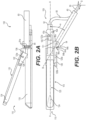
- FIG. 2B illustrates a top view of end effector 100 in the open configuration.
- a locking tab 126 is connected to anvil 120 via pin 120a and a second pin 120b, distal of pin 120a. Through those connections locking tab 126 moves with anvil 120. It will be understood that locking tab 126 may be connected to anvil 120 via any other mechanism known in the art. According to an example, pin 120b may engage a second slot, distal to slot 136, in the closed configuration, which may lock anvil 120 in the closed configuration.
- Pivot arm 60 may include a pivot head 64 at the distal end thereof. Pivot head 64 may include a plurality of teeth 64a defining a plurality of spaces 64b therebetween. Locking tab 126 may engage spaces 64b, as will be described herein. Teeth 64a and spaces 64b may be spaced apart radially about a circumference of pivot head 64 ( FIG. 2C ) such that stapler device 110 may be locked at an angle relative to pivot arm 60. For example, an angle ⁇ is defined as an angle between the longitudinal axis A-A of stapler device 110 and the longitudinal axis B-B of pivot arm 64.
- pivot arm 60 When ⁇ is 0 degrees, pivot arm 60 may be approximately parallel to stapler device 110 (axes A-A and B-B are approximately parallel), and when ⁇ is 90 degrees, pivot arm 60 may be approximately perpendicular to stapler device 110 (axes A-A and B-B are approximately perpendicular).
- teeth 64a and spaces 64b may be spaced such that stapler device 110 may be locked at an orientation relative to pivot arm 60 such that ⁇ may be one of approximately 0 degrees, approximately 30 degrees, approximately 60 degrees, and approximately 90 degrees. It will be understood that ⁇ is not limited to these angles.
- the number of teeth 64a and spaces 64b, and their spacing, may determine the various angles ⁇ of locking stapler device 110 relative to pivot head 64.
- teeth 64a may be positioned on pivot head 64 to change the angle of ⁇ .
- the number of teeth 64a is not limited to three teeth 64a, as shown in FIGS. 2A and 2B , and may be chosen based on the number of designed locking angles.
- FIGS. 3A and 3B illustrate anvil 120 in the closed configuration.
- anvil 120 has rotated about pin 120a such that distal end 124 of anvil 120 is closer to body 130 than in the open configuration.
- locking tab 126 may communicate with teeth 64a in the closed position to prevent relative rotational or pivotal movement between stapler device 110 and pivot arm 60.
- a proximal portion of locking tab 126 may be positioned between adjacent teeth 64a in the closed configuration, which may prevent stapler device 110 from rotating relative to pivot arm 60.
- the desired positioning/orientation of stapler device 110 may be assisted by an imaging device associated, for example, with an endoscope through which apparatus 10 is inserted.
- the user may move wire 40a in a proximal direction (e.g., pull on wire 40a) and thereby move anvil 120 into the closed configuration using, e.g., handle assembly 30.
- locking tab 126 may engage spaces 64b in a locked position and may prevent rotation of stapler device 110 about the axis defined by pin 60a. While in this locked position, the user may perform additional procedures, e.g., stapling, cutting, or other procedures on the tissue.
- the user may move (e.g., push) wire 40a in a distal direction, which may cause anvil 120 to move to the open position, thereby disengaging locking tab 126 from spaces 64b.
- the user may then rotate stapler device 110 to a new, different orientation relative to pivot arm 60. If desired, the user may relock stapler device 110 in the new orientation by repeating this procedure or the user may remove the apparatus from the body.
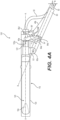
- FIGS. 4A and 4B A locking mechanism for an end effector 100' according to another example is shown in FIGS. 4A and 4B .
- End effector 100' is similar to end effector 100, and may include stapler device 110 pivotally connected to pivot arm 60.
- Locking mechanism may include a pawl 66' and a sprocket 64' having a plurality of teeth 64a'. Spaces 64b' are defined between adjacent teeth 64a'.
- Sprocket 64' may be rigidly connected to pivot arm 60 and may have an arc shape with a convex surface facing a proximal end of the end effector 100.
- Pawl 66' may be pivotally attached to body 130 of end effector 100 by a pin 66a'.
- a biasing member e.g., a spring, may bias pawl 66' in a distal direction, e.g., toward sprocket 64'.
- Pawl 66' may engage spaces 64b' to lock stapler device 110 in a desired orientation relative to pivot arm 60.
- pawl 66' may sit in any one of spaces 64b' between adjacent teeth 64a'.
- An actuation wire 40b may be attached to an end of pawl 66' opposite an end of pawl 66' connected to pin 66a'.
- Actuation wire 40b may be similar to wire 40a and may be moved proximally (e.g., pulled) and distally (e.g., pushed) to cause pawl 66' to pivot about pin 66a'.
- end effector 100' may be locked such that an orientation of stapler device 110 relative to pivot arm 60 is locked at one or more positions based on the number of teeth 64a' and spaces 64b , and the spacing of teeth 64a' and spaces 64b'.
- pivot arm 60 may be parallel to end effector 100' (axes A-A and B-B are approximately parallel)
- pivot arm 60 may be perpendicular to end effector 100' (axes A-A and B-Bare approximately perpendicular).
- angle ⁇ is not limited to these angles.
- teeth 64a' and spaces 64b' are not limited to the number shown in FIGS. 4A and 4B .
- the number of teeth 64a' and the number of spaces 64b' may be selected based on the number of possible positions stapler device 110 may be locked relative to pivot arm 60.
- teeth 64a' define seven spaces 64b' that provide different angles ⁇ between axes A-A and B-B. More or fewer spaces 64b' at different spacing may provide different angular adjustments of stapler device 110.
- End effector 100' may be introduced to the body and advanced to the target site in a similar manner as end effector 100.
- Pawl 66' is engaged with a space 64b' during insertion, so that angle ⁇ is approximately 0 degrees.
- the user may move actuation wire 40b in a proximal direction by, e.g., pulling on actuation wire 40b. Proximal movement of actuation wire 40b may cause pawl 66' to rotate about pin 66a' and disengage pawl 66' from a space 64b' and teeth 64a' of sprocket 64'.
- the user may orient stapler device 110 as desired relative to the tissue and/or target site in a manner similar to orienting stapler device 110 as discussed with reference to FIGS. 2A and 2B , e.g., by moving elongated body 50 in a proximal or distal direction, thereby changing angle ⁇ .
- the user may release and/or push actuation wire 40b in the distal direction. For example, if pawl 66' is biased toward sprocket 64', releasing actuation wire 40b may cause pawl 66' to engage a space 64b' between teeth 64a'.
- a distal force applied to actuation wire 40b may be necessary for such engagement.
- stapler device 110 may be locked in the selected orientation and the user may perform additional procedures. For example, the user may then move anvil 120 from the open configuration to the closed configuration by moving actuation wire 40a proximally and/or may perform additional medical procedures, e.g., stapling, cutting, or other procedures on the tissue.
- additional medical procedures e.g., stapling, cutting, or other procedures on the tissue.
- pawl 66' may again be disengaged from teeth 64a' and stapler device 110 may be rotated about the axis defined by pin 60a as described herein.
- Locking mechanism 64' of FIGS. 4A and 4B permits locking of stapler device 110 relative to pivot arm 60, independent of opening and closing of anvil 120.
- End effector 100" is similar to end effectors 100 and 100', e.g., may include stapler device 110 and pivot arm 60.
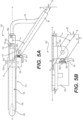
- the locking mechanism may include a ball-nose spring plunger 64", including a housing 150 fixed to body 130 of stapler device 110.
- Ball-nose spring plunger 64" may include detents 64c" (notches) disposed on a distal end of pivot arm 60, a biasing member 64a" (e.g., a spring, a threaded housing having a spring and a ball-bearing or a plunger, or any other biasing member) disposed in (or on) housing 150 and configured to extend out of a proximal end of housing 150, and a ball bearing 64b". Ball bearing 64b" is inserted within an interior of biasing member 64a” so that ball bearing 64b” is held by biasing member 64a", rotates relative to biasing member 64a", and protrudes from an end of biasing member 64a".
- a biasing member 64a e.g., a spring, a threaded housing having a spring and a ball-bearing or a plunger, or any other biasing member
- Ball bearing 64b is inserted within an interior of biasing member 64a” so that ball bearing 64b” is held by biasing
- movement of elongated body 50 relative to pivot arm 60 may rotate end effector 100" about the axis defined by pin 60a.
- Distal movement of elongated body 50 may increase angle ⁇ and may cause biasing member 64a" to be compressed within housing 150.
- stapler device 110 rotates about the axis defined by pin 60a, which may cause the protruding material between detents 64c" (teeth) to push against ball bearing 64b", thereby compressing biasing member 64a" into housing 150.
- Biasing member 64a", ball bearing 64b", and detents 64c” may cooperate to lock stapler device 110 at different orientation angles ⁇ relative to pivot arm 60.
- a friction force holds ball bearing 64b" within the corresponding detent 64c".
- biasing member 64a" is compressed until the friction force between detent 64c" and ball bearing 64b" is overcoming. Overcoming this friction force causes ball bearing 64b" to move from the first detent 64c" to a second detent 64c", adjacent the first detent 64c". Once ball bearing 64b" moves to the second detent 64c", biasing member 64a" expands back to the original length/position. Additional distal movement of elongated body 50 may cause stapler device 110 to pivot about the pivot axis defined by pin 60a, causing biasing member 64a" to again compress.
- a force on elongated body 50 in the proximal direction e.g., a pulling force
- a force on elongated body 50 in the proximal direction e.g., a pulling force
- stapler device 110 moves relative to pivot arm 60 such that angle ⁇ decreases.
- the number of detents 64c" and the spacing between adjacent detents 64c" may be selected based on the number of possible positions stapler device 110 may be locked relative to pivot arm 60. A smaller ball bearing and smaller detents may result in finger adjustments of angle ⁇ and more options for angle ⁇ .
- End effector 100" may be introduced to the body and advanced to the target site in a similar manner as end effectors 100 and 100'. End effector 100 is advanced to the target site in a closed position and is opened by actuation of actuation wire 40a. During insertion, ball bearing 64b" may be engaged with a first detent 64c" so that angle ⁇ is approximately 0 degrees, e.g., so that axes A-A and B-B are approximately parallel. Once end effector 100" is adjacent the target site, the user may rotate stapler device 110 about the pivot axis defined by pin 60a by pushing elongate member 50 in the distal direction.
- the distal movement of elongate member 50 may cause angle ⁇ to increase and may cause biasing member 64a" to compress within housing 150.
- biasing member 64a" As biasing member 64a” is compressed from the original length into housing 150, a second detent 64c", adjacent to the first detent 64c", engages ball bearing 64b" and biasing member 64a” expands to the original length. Friction forces between ball bearing 64b" and the second detent 64c” lock stapler device 110 relative to pivot arm 60.
- the user may continue to push elongated member 50 in the distal direction until a desired orientation of stapler device 110 relative to pivot arm 60, e.g., a desired angle ⁇ , is achieved.
- elongated member 50 may be pulled in a proximal direction. Such movement causes spring 64b" to be compressed into housing 150, moving ball bearing 64b" from, e.g., the second detent 64c" to the first detent 64c". In this manner, the orientation of stapler device 110 relative to pivot arm 60 may be selected and locked. Locking mechanism 64" of FIGS. 5A and 5B permits locking and unlocking of stapler device 110 relative to pivot arm 60, independent of opening and closing of anvil 120.
Landscapes
- Health & Medical Sciences (AREA)
- Surgery (AREA)
- Life Sciences & Earth Sciences (AREA)
- Medical Informatics (AREA)
- Animal Behavior & Ethology (AREA)
- Engineering & Computer Science (AREA)
- Biomedical Technology (AREA)
- Heart & Thoracic Surgery (AREA)
- Veterinary Medicine (AREA)
- Molecular Biology (AREA)
- Nuclear Medicine, Radiotherapy & Molecular Imaging (AREA)
- General Health & Medical Sciences (AREA)
- Public Health (AREA)
- Ophthalmology & Optometry (AREA)
- Surgical Instruments (AREA)
- Mechanical Pencils And Projecting And Retracting Systems Therefor, And Multi-System Writing Instruments (AREA)
- Absorbent Articles And Supports Therefor (AREA)
Abstract
Description
- This application claims the benefit of priority from
U.S. Provisional Application No. 62/969,738, filed on February 4, 2020 - This disclosure relates to minimally invasive (e.g., endoscopic and/or laparoscopic) medical devices and related methods of use. In embodiments, the disclosure relates to one or more locking mechanisms for end effectors, e.g., tissue fastening devices such as stapler devices, and related methods of use, among other aspects.
- Technological developments have given users of medical systems, devices, and methods, the ability to conduct increasingly complex procedures on patients. The grasping and/or coupling of tissue in a patient's body, for example, may be performed by surgical devices that grasp or clamp tissue between opposing jaw structures and then fasten or cut the tissue. A drawback of these systems may include, for example, maintaining a desired orientation of the jaws of an end effector during a procedure, such as a stapling procedure, a cutting procedure, and/or additional medical procedures. For example, to access tissue, an end effector may be articulated about a pivot point. During a cutting or a fastening step, actuation of the cutting and/or fastening device may cause the end effector to pivot from the selected orientation to a different, undesired orientation. Thus, tissue may not be properly stapled and/or cut, which may increase therapy time and/or cost, may cause undesired or incomplete fastening of tissues, and/or may require additional therapy/intervention at the target site. This disclosure may solve one or more of these problems or other problems in the art. The scope of the disclosure, however, is defined by the attached claims and not the ability to solve a specific problem.
- According to an aspect, a medical device includes an end effector at a distal end of the medical device, an actuator coupled to a proximal end of the end effector, a pivot arm pivotally coupled to the end effector distal of the proximal end of the end effector, where actuation of the actuator pivots the end effector relative to the pivot arm, and a lock on the end effector and the pivot arm, where the lock has a first state permitting the end effector to pivot relative to the pivot arm and a second state restricting the end effector from pivoting relative to the pivot arm.
- The end effector may include a first jaw, and a second jaw hingedly connected to the first jaw and configured to move between an open position and a closed position.
- The locking mechanism may include a plurality of teeth at a distal end of the pivot arm, wherein the plurality of teeth may define a plurality of spaces, and a tab connected to the end effector, wherein the tab may be configured to engage a space from the plurality of spaces in the second state.
- The lock is in the first state when the pair of jaws is in the open position, and the lock is in the second state when the pair of jaws is in the closed position.
- The end effector may be configured to pivot independently of a movement of the first jaw relative to the second jaw.
- The locking mechanism may include a sprocket connected to the pivot arm, wherein the sprocket may include a plurality of teeth defining a plurality of spaces, and a pawl pivotally connected at the proximal end of the end effector and may be configured to engage the plurality of spaces.
- The medical device may further comprise a wire connected to the pawl and extending in a proximal direction, wherein the pawl may be biased into engagement with the plurality of spaces of the sprocket, and wherein moving the wire in the proximal direction may be configured to pivot the pawl away from the sprocket to disengage the pawl from the plurality of spaces.
- The sprocket may be arc shaped, and wherein a convex arrangement of the plurality of spaces of the sprocket may face proximally.
- The locking mechanism may include a ball-nose spring plunger.
- The ball-nose spring plunger may include a spring coupled at a first end of the end effector, wherein the spring may be configured to extend from the first end and compress along a compression axis, a plurality of detents fixed to the pivot arm, and a ball bearing connected to the spring and selectively engaging each of the plurality of detents, wherein the ball bearing may be configured to move along the compression axis.
- The ball bearing may be configured to move from a first detent of the plurality of detents to an adjacent, second detent of the plurality of detents as the end effector pivots about the pivot arm and wherein the spring may be configured to be compressed from a first position to a second position and expand back to the first position as the ball bearing moves from the first detent to the second detent.
- The medical device may further comprise an actuation wire fixed to a proximal end of the end effector, wherein actuation of the actuation wire may be configured to move the end effector between an open position and a closed position.
- The pivot arm may include a first opening at a proximal end of the pivot arm, a second opening in a sidewall of the pivot arm, and a lumen extending from the first opening to the second opening. The actuator may be configured to extend through each of the first opening, the lumen, and the second opening.
- The medical device may further comprise a handle assembly configured to actuate the end effector and the locking mechanism, wherein a proximal end of the actuator may be connected to a distal end of the handle assembly, and a catheter may include at least one lumen and may extend distally from the handle assembly, wherein the actuator may extend through the at least one lumen, and wherein the pivot arm may be fixed to a distal end of the catheter.
- A pivot angle may be defined between a longitudinal axis of the end effector and a longitudinal axis of the pivot arm, wherein a distal movement of the actuator may be configured to increase the pivot angle, and wherein a proximal movement of the actuator may be configured to decrease the pivot angle.
- According to another aspect, a medical device comprises an elongated member, an end effector connected to a distal end of the elongated member, wherein the end effector may include a tab, and a catheter including a plurality of spaces at a distal end, wherein the tab may be configured to selectively engage the plurality of spaces to inhibit pivotal movement of the end effector.
- The elongated member may extend through an opening of the catheter proximally of a distal end of the catheter, and wherein the end effector may be pivotally coupled to the catheter distally of the opening.
- According to another aspect, a medical method includes advancing an end effector and a pivot arm to a target site within a patient, pivoting the end effector relative to the pivot arm about a pivot axis until a desired orientation of the end effector is achieved, locking the orientation of the end effector relative to the pivot arm, and performing an operation via the end effector.
- The end effector may include a first jaw, and a second jaw hingedly connected to the first jaw, wherein the end effector may include an open configuration and a closed configuration, and wherein a distance between distal ends of the first jaw and the second jaw may be greater in the open configuration than a distance between the distal ends of the first jaw and the second jaw in the closed configuration.
- When the end effector is in the closed configuration, the end effector may be locked relative to the pivot arm, and when the end effector is in the open configuration, the end effector may be unlocked relative to the pivot arm.
- The accompanying drawings, which are incorporated in and constitute a part of this specification, illustrate various exemplary embodiments and together with the description, serve to explain the principles of the disclosed embodiments.
-
FIG. 1 is a schematic view of a tissue fastening device according to an embodiment; -
FIGS. 2A and 2B are views of an end effector of the fastening device ofFIG. 1 , according to an embodiment; -
FIG. 2C is a view of a pivot arm of the end effector ofFIGS. 2A and 2B ; -
FIGS. 3A and 3B are views of an end effector of the fastening device ofFIG. 1 , according to an embodiment; -
FIGS. 4A and4B are views of an end effector of the fastening device ofFIG. 1 , according to another embodiment; -
FIG. 5A is a view of an end effector of the fastening device ofFIG. 1 , according to another embodiment; and -
FIG. 5B is a view of a locking mechanism of the end effector ofFIG. 5A . - This disclosure is described with reference to exemplary medical systems and medical tools for accessing a target site, for example, for grasping, cutting, and/or stapling tissue. This may provide improved medical tool functionality and/or may assist medical professionals to improve cutting and/or fastening of tissue. However, it should be noted that reference to any particular device and/or any particular procedure is provided only for convenience and not intended to limit the disclosure. A person of ordinary skill in the art would recognize that the concepts underlying the disclosed devices and application methods may be utilized in any suitable procedure, medical or otherwise. This disclosure may be understood with reference to the following description and the appended drawings, wherein like elements are referred to with the same reference numerals.
- For ease of description, portions of the disclosed devices and/or their components are referred to as proximal and distal portions. It should be noted that the term "proximal" is intended to refer to portions closer to a user of the devices, and the term "distal" is used herein to refer to portions further away from the user. Similarly, "extends distally" indicates that a component extends in a distal direction, and "extends proximally" indicates that a component extends in a proximal direction. Further, as used herein, the terms "about," "approximately," and "substantially" indicate a range of values within +/- 10% of a stated or implied value. Additionally, terms that indicate the geometric shape of a component/surface refer to exact and approximate shapes.
- Embodiments of this disclosure may be used to cut and/or fasten tissue in an endo-luminal space, or facilitate the process thereof. According to an example, the fastening device may be a tissue stapling apparatus, which may include a resection or cutting mechanism (e.g., an integrated knife) and a stapling mechanism (e.g., a stapler). The fastening device may be delivered through an endoscope working channel to the target tissue site. All or parts of the fastening device could be metallic (such as stainless steel, titanium, or cobalt chrome), plastic (such as polyetheretherketone (PEEK) or the like), or include a shape memory metal (such as nitinol), a shape memory polymer, a polymer, or any combination of materials. While reference is made herein to a fastening device, the described locking members may be used with any device pivotally connected to a distal end of a catheter, sheath, tube, or the like. The locking members may prevent pivotal movement of an end effector or other device pivotally connected to the distal end of, e.g., the catheter. This may improve an operation of the end effector. For example, preventing a pivotal rotation of a stapler during stapling may improve the connection between the adjacent tissues.
-
FIG. 1 shows anapparatus 10 in accordance with an example of this disclosure.Apparatus 10 may be a surgical stapling apparatus configured to engage body tissue, and apply a plurality of fasteners thereto during minimally invasive procedures, such as laparoscopic or endoscopic procedures. In someembodiments apparatus 10 may be a suturing apparatus to delivering a suture for tissue closure during minimally invasive surgical procedures.Apparatus 10 may be used to apply a suture, clips, or other fasteners, but will be primarily discussed in the context of grasping tissue in preparation of performing additional procedures to the tissue, e.g., stapling and/or cutting the tissue. - As illustrated in
FIG. 1 ,apparatus 10 includes ahandle assembly 30 at a proximal end, anend effector 100 at a distal end, and an elongated body 50 (e.g., a catheter or the like) connecting a distal end ofhandle assembly 30 to a proximal end of end effector 100 (as will be explained herein,end effector 100 may include a stapler device 110).Elongated body 50 may extend any length suitable for endoscopic or laparoscopic procedures, and may be configured to be positioned within a working channel of an endoscope. Alternatively,elongated body 50 may extend along an outer surface of the endoscope if, for example, the endoscope includes only a single lumen and/or a diameter of the lumen(s) of the endoscope are too small to receiveelongated body 50.Elongated body 50 may be detachable fromhandle assembly 30 to facilitate insertion ofelongated body 50 into a working channel of an endoscope or a channel of another device, for example by backloadingelongated body 50 into the working channel. In some examples,elongated body 50 may be flexible, steerable, and/or may be rotatable about its axis.Elongated body 50 may include a lumen (or multiple lumens) for positioning actuation wires within, for actuatingend effector 100 viahandle assembly 30 or actuating any other portion ofapparatus 10.Elongated body 50 may be configured to receive a plurality of actuation wires or a single actuation wire. In some examples,elongated body 50 may be fixedly coupled to endeffector 100, and in other examples elongatedbody 50 may be removably or releasably coupled to endeffector 100. Unless stated otherwise, any wire or actuation device described herein may extend fromhandle assembly 30 to endeffector 100 via a lumen ofelongated body 50. Alternatively, or additionally, one or more of these actuation wires or devices may extend fromhandle assembly 30 to endeffector 100 outside of (e.g., adjacent to)elongated body 50. A catheter 55 (or any other sheath) including a lumen may extend distally from a distal end ofhandle assembly 30.Elongated body 50 may be disposed within the lumen ofcatheter 55 and may move relative tocatheter 55. Whilecatheter 55 is shown with a curved region inFIG. 1 ,catheter 55 may be a straight sheath (e.g., such as a hypotube) having a rigidity sufficient to be moved proximally and distally within the body. Additionally,FIGS. 2A-2C ,3A ,3B ,4A ,4B ,5A, and 5B may be shown withoutcatheter 55 attached to the proximal end of apivot arm 60 for ease of understanding (e.g., to visualize elongated body 50). - Handle
assembly 30 may include a handle 32 and abody 34. Handle 32 may include a fixedportion 32a and anactuator portion 32b.Fixed portion 32a of handle 32 may be fixedly coupled tobody 34.Actuator portion 32b may include a circular or oval portion or ring for positioning a user's finger within, which may assist a user in holdinghandle assembly 30. In some examples,actuator portion 32b of handle 32 may be an actuator which may be pivotally coupled tobody 34 and movable relative to fixedportion 32a of handle 32. In some examples,actuator portion 32b of handle 32 may be coupled to a proximal portion of an actuation wire, such as anactuation wire 40a, via anadjustable coupler 36, as will be described herein. Ananvil 120 ofstapler device 110 may be actuated viaactuation wire 40a, which extends betweenstapler device 110 and handleassembly 30. In other examples,actuator portion 32b of handle 32 may be configured to control any other mechanism ofapparatus 10, such as operating an articulation lock ofend effector 100, actuation of the deployment of staples fromstapler device 110, or the like. It will be understood thatwire 40a may have sufficient rigidity to be pushed in the distal direction and pulled in the proximal direction. - In some examples, handle
assembly 30 may include amoveable cover 38 pivotally coupled tohousing 34 atpivot point 38b. InFIG. 1 , cover 38 is shown in an open position, exposing the internal portions ofbody 34.Cover 38 may be coupled to a proximal portion ofbody 34 and may cover the internal components ofhandle assembly 30 when positioned in a closed configuration, e.g., when adistalmost end 38a ofcover 38 faces asurface 34a ofbody 34.Cover 38 may be positioned to cover the internal components of body 34 (e.g., a closed configuration) via a coupling mechanism at a distal portion ofcover 38 and a distal portion ofhandle assembly 30, such as a snap-fit mechanism or the like. When in the closed configuration, cover 38 may form a pair of slots in body 34 (not shown). When the distal portion ofcover 38 is uncoupled from the distal portion ofbody 34, a user may rotate or pivotcover 38 atpivot point 38b in order to access to the internal components ofhandle assembly 30. - Handle
assembly 30 may include one or moreadjustable couplers actuation wire 40a. Any ofadjustable couplers actuation wire 40a and fixedlycouple actuation wire 40a to theadjustable couplers adjustable couplers couplers actuation wire 40a fromcouplers Couplers -
Adjustable coupler 39 may be coupled tolongitudinal actuator 31 and moveable longitudinally via translatinglongitudinal actuator 31 withinbody 34.Longitudinal actuator 31 may be partially positioned withinhousing 34 and may be slidable longitudinally within the two slots formed whencover 38 is positioned over the internal components ofhandle assembly 30.Longitudinal actuator 31 may include a pair of opposing circular or oval portions or rings, with each circular portion defining an aperture for a user to position a respective finger within. In some examples,longitudinal actuator 31 may be coupled to an actuation wire (not shown), such as viaadjustable coupler 39 or via a different coupler withinbody 34, and may be configured to control staple deployment fromstapler device 110. In other examples,longitudinal actuator 31 may be configured to control any other mechanism ofapparatus 10, such as actuation of ananvil 120 ofstapler device 110, actuation of a locking mechanism associated withend effector 100, or the like. - With continued reference to
FIG. 1 ,end effector 100 includesstapler device 110 which may be pivotally coupled to the distal end ofelongated body 50. For example, aconnector 52 at a distal end ofelongated body 50 may be pivotally attached to a proximal end ofstapler device 110 via apin 52a or the like. Apivot arm 60 may be pivotally attached to a side of abody 130 ofstapler device 110 via apin 60a. For example, one ormore protrusions 131 may extend from the side ofbody 130 and may receivepin 60a through an opening inprotrusion 131, thereby fixingpin 60a relative toprotrusion 131.Pin 60a defines a pivot axis ofstapler device 110 relative to pivotarm 60.Pin 60a may also be received in anopening 66 at a distal end of pivot arm 60 (FIG. 2C ), which may allowstapler device 110 to pivot relative to pivotarm 60.Pivot arm 60 may be fixedly attached to a distal end ofcatheter 55 by ultrasonic welding, adhesive, crimping, or the like. This may preventpivot arm 60 from moving whenelongated member 50 is moved relative tocatheter 55 and/orpivot arm 60, as will be described herein. For ease of understanding,catheter 55 is shown only inFIG. 1 . - As shown in
FIG. 2A ,pivot arm 60 may include an opening 62 at a proximal end. Opening 62 may be connected to a lumen extending from the proximal end to the distal end ofarm 60. A slot 65 (e.g., an opening) (FIG. 2C ) may be formed in a side ofpivot arm 60 and may be connected to the lumen ofpivot arm 60.Slot 65 may be oval, rectangular, or any other suitable shape. Opening 62, the lumen ofpivot arm 60, andslot 65 may be sized and shaped to receive a portion ofelongated body 50, such thatelongated body 50 may enterpivot arm 60 via opening 62 and extend out ofslot 65. As will be described herein, movement ofelongated body 50 relative to pivotarm 60 may causestapler device 110 to rotate relative to pivotarm 60.Pivot arm 60 shown inFIG. 2C , or aspects ofpivot arm 60 includingslot 65, may be used with any end effector described herein. Whilepivot arm 60 is shown as a rectangular prism,pivot arm 60 may be any shape, including a cylinder, a rectangular prism with rounded edges, or the like. -
Anvil 120 may be rotatably or pivotally coupled tobody 130 viapin 120a (pin 120a may define a pivot axis).Anvil 120 andbody 130 may be collectively referred to as jaws, grasping elements, and/or opposing members.Anvil 120 may extend distally towards a distal end ofstapler device 110 frompin 120a. In some examples,anvil 120 may be rotatably biased aboutpin 120a and may be biased in an open configuration. For example, adistal end 124 ofanvil 120 may biased away frombody 130 using a spring or the like, thereby creating a space betweendistal end 124 ofanvil 120 and a distal portion ofbody 130.Anvil 120 may rotate aboutpin 120a and may contact or may approachbody 130 in a closed position, e.g., to retain tissue betweenanvil 120 andbody 130. In some examples,body 130 may include a channel that supports a cartridge of staples or other fastening devices (not shown). The closed position ofanvil 120 may provide a surface for which staples may be driven against when ejected from the cartridge ofstapler device 100. The cartridge may contain a plurality of surgical fasteners, such as staples, and the fasteners may be deployed from the cartridge when under the influence of a driving force exerted by an actuation sled or other actuation mechanism. Suitable staplers and associated actuation mechanisms are described in commonly-ownedU.S. Provisional Patent Application No. 62/812,538, filed March 1, 2019 - With reference to
FIGS. 2A and 2B ,pin 120a may extend from a side ofanvil 120, andpin 120a may be disposed in a slot 136 on a side ofbody 130. For example, slot 136 may be disposed in an upper extension ofbody 130. In addition to pivoting aboutpin 120a,anvil 120 may move in a longitudinal direction viapin 120a and slot 136. For example,pin 120a ofanvil 120 may move within slot 136, which has a generally oval shape and extends in a longitudinal direction along a longitudinal axis. Slot 136 may be any shape, and may alternatively be a hole that fixes a longitudinal position ofpin 120a. In the embodiment shown inFIGS. 2A and 2B , whenpin 120a is located at a distal end of slot 136,anvil 120 may be positioned in the open configuration, andanvil 120 may be in the closed position whenpin 120a is positioned at a proximal end of slot 136.Wire 40a may be attached at aproximal end 122 ofanvil 120 via anattachment mechanism 122a. Proximal movement ofwire 40a may causeanvil 120 to move proximally, which may causeanvil 120 to rotate aboutpin 120a into the closed position. Distal movement ofwire 40a may causeanvil 120 to move distally, which may causeanvil 120 to rotate aboutpin 120a into the open position. -
FIG. 2B illustrates a top view ofend effector 100 in the open configuration. Alocking tab 126 is connected toanvil 120 viapin 120a and asecond pin 120b, distal ofpin 120a. Through thoseconnections locking tab 126 moves withanvil 120. It will be understood that lockingtab 126 may be connected toanvil 120 via any other mechanism known in the art. According to an example,pin 120b may engage a second slot, distal to slot 136, in the closed configuration, which may lockanvil 120 in the closed configuration. -
Pivot arm 60 may include apivot head 64 at the distal end thereof.Pivot head 64 may include a plurality ofteeth 64a defining a plurality ofspaces 64b therebetween. Lockingtab 126 may engagespaces 64b, as will be described herein.Teeth 64a andspaces 64b may be spaced apart radially about a circumference of pivot head 64 (FIG. 2C ) such thatstapler device 110 may be locked at an angle relative to pivotarm 60. For example, an angle α is defined as an angle between the longitudinal axis A-A ofstapler device 110 and the longitudinal axis B-B ofpivot arm 64. When α is 0 degrees,pivot arm 60 may be approximately parallel to stapler device 110 (axes A-A and B-B are approximately parallel), and when α is 90 degrees,pivot arm 60 may be approximately perpendicular to stapler device 110 (axes A-A and B-B are approximately perpendicular). According to an example,teeth 64a andspaces 64b may be spaced such thatstapler device 110 may be locked at an orientation relative to pivotarm 60 such that α may be one of approximately 0 degrees, approximately 30 degrees, approximately 60 degrees, and approximately 90 degrees. It will be understood that α is not limited to these angles. The number ofteeth 64a andspaces 64b, and their spacing, may determine the various angles α of lockingstapler device 110 relative to pivothead 64. For example,teeth 64a may be positioned onpivot head 64 to change the angle of α. Further, the number ofteeth 64a is not limited to threeteeth 64a, as shown inFIGS. 2A and 2B , and may be chosen based on the number of designed locking angles. -
FIGS. 3A and 3B illustrateanvil 120 in the closed configuration. In the closed configuration,anvil 120 has rotated aboutpin 120a such thatdistal end 124 ofanvil 120 is closer tobody 130 than in the open configuration. As shown inFIG. 3B , lockingtab 126 may communicate withteeth 64a in the closed position to prevent relative rotational or pivotal movement betweenstapler device 110 andpivot arm 60. For example, a proximal portion of lockingtab 126 may be positioned betweenadjacent teeth 64a in the closed configuration, which may preventstapler device 110 from rotating relative to pivotarm 60. - A method of operating
end effector 100 will now be described.End effector 100 may be advanced to a target site in a body via an incision or a natural orifice.End effector 100 is advanced in a closed configuration and subsequently opened via actuation ofactuation wire 40a. In the open configuration, tissue at the target site may be placed betweenanvil 120 and body 130 (e.g., jaws) ofstapler device 110, via any suitable method. To properly orientstapler device 110, a user may push distally or pull proximally onelongated body 50 to causestapler device 110 to pivot about the axis defined bypin 60a until a desired orientation ofstapler device 110 relative to pivotarm 60 is achieved (e.g., a desired angle α). The desired positioning/orientation ofstapler device 110 may be assisted by an imaging device associated, for example, with an endoscope through whichapparatus 10 is inserted. After the desired orientation is achieved, the user may movewire 40a in a proximal direction (e.g., pull onwire 40a) and thereby moveanvil 120 into the closed configuration using, e.g., handleassembly 30. Asanvil 120 moves into the closed configuration, lockingtab 126 may engagespaces 64b in a locked position and may prevent rotation ofstapler device 110 about the axis defined bypin 60a. While in this locked position, the user may perform additional procedures, e.g., stapling, cutting, or other procedures on the tissue. Once the procedure is complete, the user may move (e.g., push)wire 40a in a distal direction, which may causeanvil 120 to move to the open position, thereby disengaginglocking tab 126 fromspaces 64b. The user may then rotatestapler device 110 to a new, different orientation relative to pivotarm 60. If desired, the user may relockstapler device 110 in the new orientation by repeating this procedure or the user may remove the apparatus from the body. - A locking mechanism for an end effector 100' according to another example is shown in
FIGS. 4A and4B . End effector 100' is similar to endeffector 100, and may includestapler device 110 pivotally connected to pivotarm 60. Locking mechanism may include a pawl 66' and a sprocket 64' having a plurality ofteeth 64a'.Spaces 64b' are defined betweenadjacent teeth 64a'. Sprocket 64' may be rigidly connected to pivotarm 60 and may have an arc shape with a convex surface facing a proximal end of theend effector 100. Pawl 66' may be pivotally attached tobody 130 ofend effector 100 by apin 66a'. A biasing member, e.g., a spring, may bias pawl 66' in a distal direction, e.g., toward sprocket 64'. Pawl 66' may engagespaces 64b' to lockstapler device 110 in a desired orientation relative to pivotarm 60. For example pawl 66' may sit in any one ofspaces 64b' betweenadjacent teeth 64a'. Anactuation wire 40b may be attached to an end of pawl 66' opposite an end of pawl 66' connected to pin 66a'.Actuation wire 40b may be similar towire 40a and may be moved proximally (e.g., pulled) and distally (e.g., pushed) to cause pawl 66' to pivot aboutpin 66a'. - As with
end effector 100, end effector 100' may be locked such that an orientation ofstapler device 110 relative to pivotarm 60 is locked at one or more positions based on the number ofteeth 64a' andspaces 64b , and the spacing ofteeth 64a' andspaces 64b'. For example, when α is 0 degrees,pivot arm 60 may be parallel to end effector 100' (axes A-A and B-B are approximately parallel), and when α is 90 degrees,pivot arm 60 may be perpendicular to end effector 100' (axes A-A and B-Bare approximately perpendicular). It will be understood that angle α is not limited to these angles. Further,teeth 64a' andspaces 64b' are not limited to the number shown inFIGS. 4A and4B . The number ofteeth 64a' and the number ofspaces 64b' may be selected based on the number of possiblepositions stapler device 110 may be locked relative to pivotarm 60. For example,teeth 64a' define sevenspaces 64b' that provide different angles α between axes A-A and B-B. More orfewer spaces 64b' at different spacing may provide different angular adjustments ofstapler device 110. - A method of operating end effector 100' will now be described. End effector 100' may be introduced to the body and advanced to the target site in a similar manner as
end effector 100. Pawl 66' is engaged with aspace 64b' during insertion, so that angle α is approximately 0 degrees. Once end effector 100' is adjacent the target site, the user may moveactuation wire 40b in a proximal direction by, e.g., pulling onactuation wire 40b. Proximal movement ofactuation wire 40b may cause pawl 66' to rotate aboutpin 66a' and disengage pawl 66' from aspace 64b' andteeth 64a' of sprocket 64'. After pawl 66' is disengaged fromspace 64b' andteeth 64a', the user may orientstapler device 110 as desired relative to the tissue and/or target site in a manner similar to orientingstapler device 110 as discussed with reference toFIGS. 2A and 2B , e.g., by movingelongated body 50 in a proximal or distal direction, thereby changing angle α. Oncestapler device 110 is properly oriented, the user may release and/or pushactuation wire 40b in the distal direction. For example, if pawl 66' is biased toward sprocket 64', releasingactuation wire 40b may cause pawl 66' to engage aspace 64b' betweenteeth 64a'. Alternatively, or additionally, a distal force applied toactuation wire 40b may be necessary for such engagement. Once pawl 66' engages aspace 64b' betweenteeth 64a',stapler device 110 may be locked in the selected orientation and the user may perform additional procedures. For example, the user may then moveanvil 120 from the open configuration to the closed configuration by movingactuation wire 40a proximally and/or may perform additional medical procedures, e.g., stapling, cutting, or other procedures on the tissue. To change the orientation ofstapler device 110 relative to pivotarm 60, pawl 66' may again be disengaged fromteeth 64a' andstapler device 110 may be rotated about the axis defined bypin 60a as described herein. Locking mechanism 64' ofFIGS. 4A and4B permits locking ofstapler device 110 relative to pivotarm 60, independent of opening and closing ofanvil 120. - A locking mechanism for an
end effector 100" according to another example is described with reference toFIGS. 5A and 5B .End effector 100" is similar to endeffectors 100 and 100', e.g., may includestapler device 110 andpivot arm 60. The locking mechanism may include a ball-nose spring plunger 64", including ahousing 150 fixed tobody 130 ofstapler device 110. Ball-nose spring plunger 64" may includedetents 64c" (notches) disposed on a distal end ofpivot arm 60, a biasingmember 64a" (e.g., a spring, a threaded housing having a spring and a ball-bearing or a plunger, or any other biasing member) disposed in (or on)housing 150 and configured to extend out of a proximal end ofhousing 150, and aball bearing 64b".Ball bearing 64b" is inserted within an interior of biasingmember 64a" so thatball bearing 64b" is held by biasingmember 64a", rotates relative to biasingmember 64a", and protrudes from an end of biasingmember 64a". - As described herein, movement of
elongated body 50 relative to pivotarm 60 may rotateend effector 100" about the axis defined bypin 60a. Distal movement ofelongated body 50 may increase angle α and may cause biasingmember 64a" to be compressed withinhousing 150. For example, as angle α increases,stapler device 110 rotates about the axis defined bypin 60a, which may cause the protruding material betweendetents 64c" (teeth) to push againstball bearing 64b", thereby compressing biasingmember 64a" intohousing 150.Biasing member 64a",ball bearing 64b", anddetents 64c" may cooperate to lockstapler device 110 at different orientation angles α relative to pivotarm 60. For example, a friction force holdsball bearing 64b" within thecorresponding detent 64c". Asstapler device 110 is rotated about the axis defined bypin 60a, biasingmember 64a" is compressed until the friction force betweendetent 64c" andball bearing 64b" is overcoming. Overcoming this friction force causesball bearing 64b" to move from thefirst detent 64c" to asecond detent 64c", adjacent thefirst detent 64c". Onceball bearing 64b" moves to thesecond detent 64c", biasingmember 64a" expands back to the original length/position. Additional distal movement ofelongated body 50 may causestapler device 110 to pivot about the pivot axis defined bypin 60a, causing biasingmember 64a" to again compress. As biasingmember 64a" is compressed,ball bearing 64b" is moved from thesecond detent 64c" to athird detent 64c", adjacent thesecond detent 64c". Continued distal movement ofelongated body 50 causes angle α between axes A-A and B-B to increase. Alternatively, or additionally, the distal end ofend effector 100" may be pushed against tissue to provide additional leverage and assist in changing angle α. - To decrease angle α, a force on
elongated body 50 in the proximal direction (e.g., a pulling force) must be sufficient to overcome the frictional forces betweenball bearing 64b" anddetents 64c". When the friction force is overcome,stapler device 110 moves relative to pivotarm 60 such that angle α decreases. The number ofdetents 64c" and the spacing betweenadjacent detents 64c" may be selected based on the number of possiblepositions stapler device 110 may be locked relative to pivotarm 60. A smaller ball bearing and smaller detents may result in finger adjustments of angle α and more options for angle α. - A method of operating
end effector 100" will now be described.End effector 100" may be introduced to the body and advanced to the target site in a similar manner asend effectors 100 and 100'.End effector 100 is advanced to the target site in a closed position and is opened by actuation ofactuation wire 40a. During insertion,ball bearing 64b" may be engaged with afirst detent 64c" so that angle α is approximately 0 degrees, e.g., so that axes A-A and B-B are approximately parallel. Onceend effector 100" is adjacent the target site, the user may rotatestapler device 110 about the pivot axis defined bypin 60a by pushingelongate member 50 in the distal direction. The distal movement ofelongate member 50 may cause angle α to increase and may cause biasingmember 64a" to compress withinhousing 150. As biasingmember 64a" is compressed from the original length intohousing 150, asecond detent 64c", adjacent to thefirst detent 64c", engagesball bearing 64b" and biasingmember 64a" expands to the original length. Friction forces betweenball bearing 64b" and thesecond detent 64c"lock stapler device 110 relative to pivotarm 60. The user may continue to pushelongated member 50 in the distal direction until a desired orientation ofstapler device 110 relative to pivotarm 60, e.g., a desired angle α, is achieved. - To decrease the angle α,
elongated member 50 may be pulled in a proximal direction. Such movement causesspring 64b" to be compressed intohousing 150, movingball bearing 64b" from, e.g., thesecond detent 64c" to thefirst detent 64c". In this manner, the orientation ofstapler device 110 relative to pivotarm 60 may be selected and locked. Lockingmechanism 64" ofFIGS. 5A and 5B permits locking and unlocking ofstapler device 110 relative to pivotarm 60, independent of opening and closing ofanvil 120. - It will be understood that any of the locking mechanisms described herein may be used alone or in combination with one or more other locking mechanisms described herein.
- While different medical systems have been described, it will be understood that the particular arrangements of elements in these fastening systems are not limited. Moreover, a size, a shape, and/or the materials of the fastening system are not limited. As described herein, there are included various locking mechanisms for maintaining an orientation of a fastening device of an end effector. For example, in certain procedures, performing various medical procedures may be improved by ensuring proper orientation of the end effector relative to the endoscope and, thus, relative to the target site/tissue.
- It will be apparent to those skilled in the art that various modifications and variations can be made to the disclosed device without departing from the scope of the disclosure. Other embodiments of the disclosure will be apparent to those skilled in the art from consideration of the specification and practice of the invention disclosed herein. It is intended that the specification and examples be considered as exemplary only, with a true scope and spirit of the invention being indicated by the following claims.
-
- 1. A medical device, comprising:
- an end effector at a distal end of the medical device;
- an actuator coupled to a proximal end of the end effector;
- a pivot arm pivotally coupled to the end effector distal of the proximal end of the end effector, wherein actuation of the actuator pivots the end effector relative to the pivot arm; and
- a lock on the end effector and the pivot arm, wherein the lock has a first state permitting the end effector to pivot relative to the pivot arm and a second state restricting the end effector from pivoting relative to the pivot arm.
- 2. The medical device of item 1, wherein the end effector includes a first jaw, and a second jaw hingedly connected to the first jaw and configured to move between an open position and a closed position.
- 3. The medical device of items 1-2, wherein the locking mechanism includes:
- a plurality of teeth at a distal end of the pivot arm, wherein the plurality of teeth define a plurality of spaces; and
- a tab connected to the end effector, wherein the tab is configured to engage a space from the plurality of spaces in the second state.
- 4. The medical device of item 2, wherein the lock is in the first state when the pair of jaws is in the open position, and the lock is in the second state when the pair of jaws is in the closed position.
- 5. The medical device of item 2, wherein the end effector is configured to pivot independently of a movement of the first jaw relative to the second jaw.
- 6. The medical device of any of items 1-2, wherein the locking mechanism includes:
- a sprocket connected to the pivot arm, wherein the sprocket includes a plurality of teeth defining a plurality of spaces; and
- a pawl pivotally connected at the proximal end of the end effector and configured to engage the plurality of spaces.
- 7. The medical device of
item 6, further comprising a wire connected to the pawl and extending in a proximal direction, wherein the pawl is biased into engagement with the plurality of spaces of the sprocket, and wherein moving the wire in the proximal direction is configured to pivot the pawl away from the sprocket to disengage the pawl from the plurality of spaces. - 8. The medical device of any of
items 6 or 7, wherein the sprocket is arc shaped, and wherein a convex arrangement of the plurality of spaces of the sprocket faces proximally. - 9. The medical device of any of items 1-2, wherein the locking mechanism includes a ball-nose spring plunger.
- 10. The medical device of
item 9, wherein the ball-nose spring plunger includes:- a spring coupled at a first end of the end effector, wherein the spring is configured to extend from the first end and compress along a compression axis;
- a plurality of detents fixed to the pivot arm; and
- a ball bearing connected to the spring and selectively engaging each of the plurality of detents, wherein the ball bearing is configured to move along the compression axis.
- 11. The medical device of
item 10, wherein the ball bearing is configured to move from a first detent of the plurality of detents to an adjacent, second detent of the plurality of detents as the end effector pivots about the pivot arm, and wherein the spring is configured to be compressed from a first position to a second position and expand back to the first position as the ball bearing moves from the first detent to the second detent. - 12. The medical device of any of the preceding items, further comprising an actuation wire fixed to a proximal end of the end effector, wherein actuation of the actuation wire is configured to move the end effector between an open position and a closed position.
- 13. The medical device of any of the preceding items, wherein the pivot arm includes:
- a first opening at a proximal end of the pivot arm;
- a second opening in a sidewall of the pivot arm; and
- a lumen extending from the first opening to the second opening; and
- wherein the actuator is configured to extend through each of the first opening, the lumen, and the second opening.
- 14. The medical device of any of the preceding items , further comprising:
- a handle assembly configured to actuate the end effector and the locking mechanism, wherein a proximal end of the actuator is connected to a distal end of the handle assembly; and
- a catheter including at least one lumen and extending distally from the handle assembly,
- wherein the actuator extends through the at least one lumen, and wherein the pivot arm is fixed to a distal end of the catheter.
- 15. The medical device of any of the preceding items, wherein a pivot angle is defined between a longitudinal axis of the end effector and a longitudinal axis of the pivot arm, wherein a distal movement of the actuator is configured to increase the pivot angle, and wherein a proximal movement of the actuator is configured to decrease the pivot angle.
Claims (15)
- A medical device, comprising:an elongated member (50);an end effector (100) connected to a distal end of the elongated member (50), wherein the end effector (100) includes a tab (126); anda catheter (55, 60) including a plurality of spaces (64b) at a distal end,wherein the tab (126) is configured to selectively engage the plurality of spaces (64b) to inhibit pivotal movement of the end effector (100).
- The medical device of claim 1,wherein the elongated member (50) extends through an opening (65) of the catheter (55, 60) proximally of a distal end of the catheter (55, 60), andwherein the end effector (100) is pivotally coupled to the catheter (55, 60) distally of the opening (65).
- The medical device of claim 1 or 2,
wherein the elongated member (50) is coupled to a proximal end of the end effector (100). - The medical device of and of the preceding claims,
wherein the catheter (55, 60) comprises a pivot arm (60) pivotally coupled to the end effector (100) distal of the proximal end of the end effector (100), wherein actuation of the elongated member (50) pivots the end effector (100) relative to the pivot arm (60). - The medical device of claim 4,
wherein the pivot arm (60) is fixedly attached to a distal end of the remaining portion of the catheter (55, 60), for example by ultrasonic welding, adhesive, or crimping. - The medical device of any of the preceding claims, wherein the catheter (55, 60) includes:
a plurality of teeth (64a) at a distal end of the catheter (60), wherein the plurality of teeth (64a) defines the plurality of spaces (64b). - The medical device of any of the preceding claims,
wherein the end effector (100) includes a stapler device (110). - The medical device of claim 7,
wherein the catheter (55, 60) is pivotally attached to a side of a body (130) of the stapler device (110) via a pin (60a), preferably wherein the pin (60a) defines a pivot axis of the stapler device (110) relative to catheter (55, 60). - The medical device of claim 8,
where the stapler device (110) comprises an anvil (120) which is rotatably or pivotally coupled to the body (130) of the stapler device (110) via a further pin (120a). - The medical device of claim 9,
wherein the further pin (120a) is disposed in a slot (136) on a side of the body (130). - The medical device of claim 10,
wherein the further pin (120a) is configured to move within the slot (136) which extends in a longitudinal direction along a longitudinal axis of the stapler device (110). - The medical device of any of the preceding claims, comprising the features of claim 9,
wherein the tab (126) is coupled to the anvil (120). - The medical device of any of the preceding claims, further comprising an actuation wire (40a) fixed to a proximal end of the end effector (100), wherein actuation of the actuation wire (40a) is configured to move the end effector (100) between an open position and a closed position.
- The medical device of any of the preceding claims, comprising the features of claim 2,wherein the opening (65) of the catheter (55, 60) is an opening in a sidewall of the catheter (55, 60),wherein the catheter (55, 60) includes:an opening at a proximal end of the catheter (55, 60); anda lumen extending from the opening at a proximal end of the catheter (55, 60) to the opening (65) in the sidewall of the catheter (55, 60); andwherein the elongated member (50) is configured to extend through each of the opening at a proximal end of the catheter (55, 60), the lumen, and the opening in the sidewall of the catheter (55, 60).
- The medical device of any of the preceding claims, further comprising:a handle assembly (30) at a proximal end of the medical device,wherein the end effector (100) is at a distal end of the medical device with the elongated body (50) connecting a distal end of the handle assembly (30) to a proximal end of the end effector (100).
Applications Claiming Priority (3)
| Application Number | Priority Date | Filing Date | Title |
|---|---|---|---|
| US202062969738P | 2020-02-04 | 2020-02-04 | |
| EP21708477.1A EP4099918B1 (en) | 2020-02-04 | 2021-02-02 | Articulation locking mechanisms for end effectors |
| PCT/US2021/016240 WO2021158562A1 (en) | 2020-02-04 | 2021-02-02 | Articulation locking mechanisms for end effectors |
Related Parent Applications (2)
| Application Number | Title | Priority Date | Filing Date |
|---|---|---|---|
| EP21708477.1A Division-Into EP4099918B1 (en) | 2020-02-04 | 2021-02-02 | Articulation locking mechanisms for end effectors |
| EP21708477.1A Division EP4099918B1 (en) | 2020-02-04 | 2021-02-02 | Articulation locking mechanisms for end effectors |
Publications (2)
| Publication Number | Publication Date |
|---|---|
| EP4544981A2 true EP4544981A2 (en) | 2025-04-30 |
| EP4544981A3 EP4544981A3 (en) | 2025-06-25 |
Family
ID=74759514
Family Applications (2)
| Application Number | Title | Priority Date | Filing Date |
|---|---|---|---|
| EP25162524.0A Pending EP4544981A3 (en) | 2020-02-04 | 2021-02-02 | Articulation locking mechanisms for end effectors |
| EP21708477.1A Active EP4099918B1 (en) | 2020-02-04 | 2021-02-02 | Articulation locking mechanisms for end effectors |
Family Applications After (1)
| Application Number | Title | Priority Date | Filing Date |
|---|---|---|---|
| EP21708477.1A Active EP4099918B1 (en) | 2020-02-04 | 2021-02-02 | Articulation locking mechanisms for end effectors |
Country Status (8)
| Country | Link |
|---|---|
| US (3) | US11759223B2 (en) |
| EP (2) | EP4544981A3 (en) |
| JP (2) | JP7646687B2 (en) |
| KR (1) | KR20220138390A (en) |
| CN (1) | CN115334980A (en) |
| AU (1) | AU2021217007A1 (en) |
| CA (1) | CA3168919A1 (en) |
| WO (1) | WO2021158562A1 (en) |
Families Citing this family (3)
| Publication number | Priority date | Publication date | Assignee | Title |
|---|---|---|---|---|
| EP3975944A4 (en) | 2019-05-28 | 2023-01-25 | Vanderbilt University | WEARABLE ASSISTIVE DEVICES AND METHODS OF OPERATION |
| JP7335211B2 (en) | 2020-09-02 | 2023-08-29 | 株式会社豊田自動織機 | METHOD FOR INTERMEDIATELY PROCESSING EXTRUDED RESIN SHEET AND METHOD FOR HEAT PRESSING INTERMEDIATE RESIN SHEET IN WHICH EXTRUDED RESIN SHEET IS INTERMEDIATELY PROCESSED |
| WO2024196582A2 (en) * | 2023-03-07 | 2024-09-26 | Vanderbilt University | Wearable assistance device with automatic clutch mechanism and method of use |
Family Cites Families (29)
| Publication number | Priority date | Publication date | Assignee | Title |
|---|---|---|---|---|
| US4728020A (en) * | 1985-08-30 | 1988-03-01 | United States Surgical Corporation | Articulated surgical fastener applying apparatus |
| US5176702A (en) * | 1991-04-04 | 1993-01-05 | Symbiosis Corporation | Ratchet locking mechanism for surgical instruments |
| US5431323A (en) * | 1992-10-09 | 1995-07-11 | Ethicon, Inc. | Endoscopic surgical instrument with pivotable and rotatable staple cartridge |
| US6010054A (en) * | 1996-02-20 | 2000-01-04 | Imagyn Medical Technologies | Linear stapling instrument with improved staple cartridge |
| US8647362B2 (en) * | 2003-10-10 | 2014-02-11 | Boston Scientific Scimed, Inc. | Device with deflectable distal end and related methods of use |
| US20060025812A1 (en) * | 2004-07-28 | 2006-02-02 | Ethicon Endo-Surgery, Inc. | Surgical instrument incorporating an electrically actuated pivoting articulation mechanism |
| US7410086B2 (en) * | 2004-07-28 | 2008-08-12 | Ethicon Endo-Surgery, Inc. | Electroactive polymer-based actuation mechanism for circular stapler |
| US7407077B2 (en) * | 2004-07-28 | 2008-08-05 | Ethicon Endo-Surgery, Inc. | Electroactive polymer-based actuation mechanism for linear surgical stapler |
| US7506790B2 (en) * | 2004-07-28 | 2009-03-24 | Ethicon Endo-Surgery, Inc. | Surgical instrument incorporating an electrically actuated articulation mechanism |
| WO2006027014A1 (en) * | 2004-09-10 | 2006-03-16 | Ethicon Endo-Surgery, Inc. | Surgical stapling instrument |
| US7121446B2 (en) * | 2004-12-13 | 2006-10-17 | Niti Medical Technologies Ltd. | Palm-size surgical stapler for single hand operation |
| US20070027468A1 (en) * | 2005-08-01 | 2007-02-01 | Wales Kenneth S | Surgical instrument with an articulating shaft locking mechanism |
| US8062306B2 (en) * | 2006-12-14 | 2011-11-22 | Ethicon Endo-Surgery, Inc. | Manually articulating devices |
| US9370341B2 (en) * | 2008-10-23 | 2016-06-21 | Covidien Lp | Surgical retrieval apparatus |
| JP6023725B2 (en) * | 2011-02-14 | 2016-11-09 | ザ ボード オブ トラスティーズ オブ ザ レランド スタンフォード ジュニア ユニバーシティー | Apparatus, system, and method for performing laparoscopic surgery |
| JP2013085619A (en) * | 2011-10-14 | 2013-05-13 | Nidec Copal Electronics Corp | Ablation catheter |
| US9186142B2 (en) * | 2013-02-28 | 2015-11-17 | Ethicon Endo-Surgery, Inc. | Surgical instrument end effector articulation drive with pinion and opposing racks |
| US9867620B2 (en) * | 2013-03-14 | 2018-01-16 | Covidien Lp | Articulation joint for apparatus for endoscopic procedures |
| WO2015152972A1 (en) * | 2014-03-31 | 2015-10-08 | Covidien Lp | Wrist and jaw assemblies for robotic surgical systems |
| US9999423B2 (en) * | 2014-06-25 | 2018-06-19 | Ethicon Llc | Translatable articulation joint unlocking feature for surgical stapler |
| US10314577B2 (en) * | 2014-06-25 | 2019-06-11 | Ethicon Llc | Lockout engagement features for surgical stapler |
| US10064620B2 (en) * | 2014-06-25 | 2018-09-04 | Ethicon Llc | Method of unlocking articulation joint in surgical stapler |
| US9855040B2 (en) * | 2015-03-04 | 2018-01-02 | Covidien Lp | Surgical stapling loading unit having articulating jaws |
| DE102015015655A1 (en) * | 2015-12-01 | 2017-06-01 | Karl Storz Gmbh & Co. Kg | Medical instrument |
| CN108882933B (en) * | 2016-02-09 | 2021-07-23 | 伊西康有限责任公司 | Surgical Instrument Articulation Mechanisms with Slotted Secondary Constraints |
| US10413291B2 (en) * | 2016-02-09 | 2019-09-17 | Ethicon Llc | Surgical instrument articulation mechanism with slotted secondary constraint |
| US11259805B2 (en) * | 2017-06-28 | 2022-03-01 | Cilag Gmbh International | Surgical instrument comprising firing member supports |
| US11484310B2 (en) * | 2017-06-28 | 2022-11-01 | Cilag Gmbh International | Surgical instrument comprising a shaft including a closure tube profile |
| CN107693068B (en) * | 2017-10-25 | 2020-09-08 | 宁波维尔凯迪医疗器械有限公司 | Angle changing mechanism and anastomat with same |
-
2021
- 2021-02-02 EP EP25162524.0A patent/EP4544981A3/en active Pending
- 2021-02-02 WO PCT/US2021/016240 patent/WO2021158562A1/en not_active Ceased
- 2021-02-02 KR KR1020227030126A patent/KR20220138390A/en not_active Ceased
- 2021-02-02 EP EP21708477.1A patent/EP4099918B1/en active Active
- 2021-02-02 CN CN202180024630.0A patent/CN115334980A/en active Pending
- 2021-02-02 JP JP2022546355A patent/JP7646687B2/en active Active
- 2021-02-02 CA CA3168919A patent/CA3168919A1/en active Pending
- 2021-02-02 AU AU2021217007A patent/AU2021217007A1/en active Pending
- 2021-02-02 US US17/165,669 patent/US11759223B2/en active Active
-
2023
- 2023-08-16 US US18/450,456 patent/US12171451B2/en active Active
-
2024
- 2024-11-08 US US18/941,378 patent/US20250064472A1/en active Pending
-
2025
- 2025-03-05 JP JP2025034303A patent/JP2025078764A/en active Pending
Also Published As
| Publication number | Publication date |
|---|---|
| JP2023512064A (en) | 2023-03-23 |
| US12171451B2 (en) | 2024-12-24 |
| EP4099918B1 (en) | 2025-04-23 |
| KR20220138390A (en) | 2022-10-12 |
| US20210236152A1 (en) | 2021-08-05 |
| CN115334980A (en) | 2022-11-11 |
| EP4544981A3 (en) | 2025-06-25 |
| US20230380853A1 (en) | 2023-11-30 |
| JP2025078764A (en) | 2025-05-20 |
| WO2021158562A1 (en) | 2021-08-12 |
| US11759223B2 (en) | 2023-09-19 |
| EP4099918A1 (en) | 2022-12-14 |
| US20250064472A1 (en) | 2025-02-27 |
| JP7646687B2 (en) | 2025-03-17 |
| AU2021217007A1 (en) | 2022-08-04 |
| CA3168919A1 (en) | 2021-08-12 |
Similar Documents
| Publication | Publication Date | Title |
|---|---|---|
| US12171451B2 (en) | Articulation locking mechanisms for end effectors and methods of use | |
| JP7778790B2 (en) | End effector control mechanism | |
| EP2036505A1 (en) | Articulating joint for surgical instruments | |
| EP3508142A2 (en) | Devices for facilitating closing and clamping of an end effector of a surgical device | |
| CN113766885A (en) | Systems, devices, and related methods for securing tissue | |
| US11883023B2 (en) | Locking mechanisms for grasping devices and methods of use | |
| EP4125628B1 (en) | Control mechanism for end effectors | |
| US12629149B2 (en) | Locking mechanisms for grasping devices and methods of use | |
| US12349932B2 (en) | Control mechanism for end effectors and method of use |
Legal Events
| Date | Code | Title | Description |
|---|---|---|---|
| PUAI | Public reference made under article 153(3) epc to a published international application that has entered the european phase |
Free format text: ORIGINAL CODE: 0009012 |
|
| STAA | Information on the status of an ep patent application or granted ep patent |
Free format text: STATUS: REQUEST FOR EXAMINATION WAS MADE |
|
| 17P | Request for examination filed |
Effective date: 20250310 |
|
| AC | Divisional application: reference to earlier application |
Ref document number: 4099918 Country of ref document: EP Kind code of ref document: P |
|
| AK | Designated contracting states |
Kind code of ref document: A2 Designated state(s): AL AT BE BG CH CY CZ DE DK EE ES FI FR GB GR HR HU IE IS IT LI LT LU LV MC MK MT NL NO PL PT RO RS SE SI SK SM TR |
|
| REG | Reference to a national code |
Ref country code: DE Ref legal event code: R079 Free format text: PREVIOUS MAIN CLASS: A61B0001000000 Ipc: A61B0017072000 |
|
| PUAL | Search report despatched |
Free format text: ORIGINAL CODE: 0009013 |
|
| AK | Designated contracting states |
Kind code of ref document: A3 Designated state(s): AL AT BE BG CH CY CZ DE DK EE ES FI FR GB GR HR HU IE IS IT LI LT LU LV MC MK MT NL NO PL PT RO RS SE SI SK SM TR |
|
| RIC1 | Information provided on ipc code assigned before grant |
Ipc: A61B 17/29 20060101ALI20250520BHEP Ipc: A61B 1/313 20060101ALI20250520BHEP Ipc: A61B 1/00 20060101ALI20250520BHEP Ipc: A61B 17/00 20060101ALI20250520BHEP Ipc: A61B 17/072 20060101AFI20250520BHEP |