EP4543022A1 - Image display apparatus - Google Patents
Image display apparatus Download PDFInfo
- Publication number
- EP4543022A1 EP4543022A1 EP24190776.5A EP24190776A EP4543022A1 EP 4543022 A1 EP4543022 A1 EP 4543022A1 EP 24190776 A EP24190776 A EP 24190776A EP 4543022 A1 EP4543022 A1 EP 4543022A1
- Authority
- EP
- European Patent Office
- Prior art keywords
- external device
- image display
- display apparatus
- audio
- controller
- Prior art date
- Legal status (The legal status is an assumption and is not a legal conclusion. Google has not performed a legal analysis and makes no representation as to the accuracy of the status listed.)
- Pending
Links
Images




Classifications
-
- H—ELECTRICITY
- H04—ELECTRIC COMMUNICATION TECHNIQUE
- H04N—PICTORIAL COMMUNICATION, e.g. TELEVISION
- H04N21/00—Selective content distribution, e.g. interactive television or video on demand [VOD]
- H04N21/40—Client devices specifically adapted for the reception of or interaction with content, e.g. set-top-box [STB]; Operations thereof
- H04N21/43—Processing of content or additional data, e.g. demultiplexing additional data from a digital video stream; Elementary client operations, e.g. monitoring of home network or synchronising decoder's clock; Client middleware
- H04N21/439—Processing of audio elementary streams
-
- G—PHYSICS
- G06—COMPUTING OR CALCULATING; COUNTING
- G06F—ELECTRIC DIGITAL DATA PROCESSING
- G06F3/00—Input arrangements for transferring data to be processed into a form capable of being handled by the computer; Output arrangements for transferring data from processing unit to output unit, e.g. interface arrangements
- G06F3/16—Sound input; Sound output
- G06F3/165—Management of the audio stream, e.g. setting of volume, audio stream path
-
- H—ELECTRICITY
- H04—ELECTRIC COMMUNICATION TECHNIQUE
- H04N—PICTORIAL COMMUNICATION, e.g. TELEVISION
- H04N21/00—Selective content distribution, e.g. interactive television or video on demand [VOD]
- H04N21/40—Client devices specifically adapted for the reception of or interaction with content, e.g. set-top-box [STB]; Operations thereof
- H04N21/43—Processing of content or additional data, e.g. demultiplexing additional data from a digital video stream; Elementary client operations, e.g. monitoring of home network or synchronising decoder's clock; Client middleware
- H04N21/439—Processing of audio elementary streams
- H04N21/4398—Processing of audio elementary streams involving reformatting operations of audio signals
-
- G—PHYSICS
- G06—COMPUTING OR CALCULATING; COUNTING
- G06F—ELECTRIC DIGITAL DATA PROCESSING
- G06F3/00—Input arrangements for transferring data to be processed into a form capable of being handled by the computer; Output arrangements for transferring data from processing unit to output unit, e.g. interface arrangements
- G06F3/14—Digital output to display device ; Cooperation and interconnection of the display device with other functional units
- G06F3/1454—Digital output to display device ; Cooperation and interconnection of the display device with other functional units involving copying of the display data of a local workstation or window to a remote workstation or window so that an actual copy of the data is displayed simultaneously on two or more displays, e.g. teledisplay
-
- G—PHYSICS
- G06—COMPUTING OR CALCULATING; COUNTING
- G06F—ELECTRIC DIGITAL DATA PROCESSING
- G06F3/00—Input arrangements for transferring data to be processed into a form capable of being handled by the computer; Output arrangements for transferring data from processing unit to output unit, e.g. interface arrangements
- G06F3/16—Sound input; Sound output
- G06F3/162—Interface to dedicated audio devices, e.g. audio drivers, interface to CODECs
-
- H—ELECTRICITY
- H04—ELECTRIC COMMUNICATION TECHNIQUE
- H04N—PICTORIAL COMMUNICATION, e.g. TELEVISION
- H04N21/00—Selective content distribution, e.g. interactive television or video on demand [VOD]
- H04N21/40—Client devices specifically adapted for the reception of or interaction with content, e.g. set-top-box [STB]; Operations thereof
- H04N21/43—Processing of content or additional data, e.g. demultiplexing additional data from a digital video stream; Elementary client operations, e.g. monitoring of home network or synchronising decoder's clock; Client middleware
- H04N21/4302—Content synchronisation processes, e.g. decoder synchronisation
- H04N21/4307—Synchronising the rendering of multiple content streams or additional data on devices, e.g. synchronisation of audio on a mobile phone with the video output on the TV screen
- H04N21/43076—Synchronising the rendering of multiple content streams or additional data on devices, e.g. synchronisation of audio on a mobile phone with the video output on the TV screen of the same content streams on multiple devices, e.g. when family members are watching the same movie on different devices
-
- H—ELECTRICITY
- H04—ELECTRIC COMMUNICATION TECHNIQUE
- H04N—PICTORIAL COMMUNICATION, e.g. TELEVISION
- H04N21/00—Selective content distribution, e.g. interactive television or video on demand [VOD]
- H04N21/40—Client devices specifically adapted for the reception of or interaction with content, e.g. set-top-box [STB]; Operations thereof
- H04N21/43—Processing of content or additional data, e.g. demultiplexing additional data from a digital video stream; Elementary client operations, e.g. monitoring of home network or synchronising decoder's clock; Client middleware
- H04N21/436—Interfacing a local distribution network, e.g. communicating with another STB or one or more peripheral devices inside the home
-
- H—ELECTRICITY
- H04—ELECTRIC COMMUNICATION TECHNIQUE
- H04N—PICTORIAL COMMUNICATION, e.g. TELEVISION
- H04N21/00—Selective content distribution, e.g. interactive television or video on demand [VOD]
- H04N21/40—Client devices specifically adapted for the reception of or interaction with content, e.g. set-top-box [STB]; Operations thereof
- H04N21/43—Processing of content or additional data, e.g. demultiplexing additional data from a digital video stream; Elementary client operations, e.g. monitoring of home network or synchronising decoder's clock; Client middleware
- H04N21/436—Interfacing a local distribution network, e.g. communicating with another STB or one or more peripheral devices inside the home
- H04N21/43615—Interfacing a Home Network, e.g. for connecting the client to a plurality of peripherals
-
- H—ELECTRICITY
- H04—ELECTRIC COMMUNICATION TECHNIQUE
- H04N—PICTORIAL COMMUNICATION, e.g. TELEVISION
- H04N21/00—Selective content distribution, e.g. interactive television or video on demand [VOD]
- H04N21/40—Client devices specifically adapted for the reception of or interaction with content, e.g. set-top-box [STB]; Operations thereof
- H04N21/43—Processing of content or additional data, e.g. demultiplexing additional data from a digital video stream; Elementary client operations, e.g. monitoring of home network or synchronising decoder's clock; Client middleware
- H04N21/436—Interfacing a local distribution network, e.g. communicating with another STB or one or more peripheral devices inside the home
- H04N21/4363—Adapting the video stream to a specific local network, e.g. a Bluetooth® network
-
- H—ELECTRICITY
- H04—ELECTRIC COMMUNICATION TECHNIQUE
- H04N—PICTORIAL COMMUNICATION, e.g. TELEVISION
- H04N21/00—Selective content distribution, e.g. interactive television or video on demand [VOD]
- H04N21/40—Client devices specifically adapted for the reception of or interaction with content, e.g. set-top-box [STB]; Operations thereof
- H04N21/43—Processing of content or additional data, e.g. demultiplexing additional data from a digital video stream; Elementary client operations, e.g. monitoring of home network or synchronising decoder's clock; Client middleware
- H04N21/436—Interfacing a local distribution network, e.g. communicating with another STB or one or more peripheral devices inside the home
- H04N21/4363—Adapting the video stream to a specific local network, e.g. a Bluetooth® network
- H04N21/43632—Adapting the video stream to a specific local network, e.g. a Bluetooth® network involving a wired protocol, e.g. IEEE 1394
- H04N21/43635—HDMI
Definitions
- the present disclosure relates to an image display apparatus.
- An image display apparatus has a function of displaying an image to a user.
- Examples of the image display apparatus may include a television (TV), a monitor, a notebook computer, and the like having a Liquid Crystal Display (LCD) using liquid crystals or an Organic Light-Emitting Diode (OLED) display using OLEDs.
- TV television
- monitor monitor
- notebook computer and the like having a Liquid Crystal Display (LCD) using liquid crystals or an Organic Light-Emitting Diode (OLED) display using OLEDs.
- LCD Liquid Crystal Display
- OLED Organic Light-Emitting Diode
- Such an image display apparatus may transceive data with various electronic devices in a wired/wireless manner.
- screen sharing technology that allows a user to share a screen of an image display apparatus currently being used by the user with another display apparatus.
- Such a screen sharing function (or service) between a plurality of image display apparatuses is used or provided under various names, including Miracast, screen mirroring, airplay, wireless display (WiDi), etc.
- a transmitting side device i.e., the sender
- a receiving side device i.e., the receiver
- resolution i.e., a supported codec, and the like
- an audio signal is transmitted by the transmitting side device regardless of the specification of the receiving side device.
- a difference occurs between the quality of audio output from the receiving side device and the quality of audio output from the transmitting side device.
- an image display apparatus includes: a display; a network interface configured to communicate with an external device; and a controller, the controller being configured to: obtain device information from the external device; based on the obtained device information, determine whether a specification of the external device in association with audio signal processing satisfies a predetermined criterion; based on a determination that the specification of the external device does not satisfy the predetermined criterion, transmit first audio data for predetermined content being displayed through the display; based on a determination that the specification of the external device does not satisfy the predetermined criterion, process an audio signal corresponding to the first audio data according to the specification of the external device; and generate second audio data corresponding to the processed audio signal to transmit the second audio data to the external device.
- An image display apparatus has the following effects.
- the external device when sharing a screen with an external device, it is possible to allow the external device to output high-quality audio compared to a specification of the external device.
- a suffix such as “module” and “unit” may be used to refer to elements or components. Use of such a suffix herein is merely intended to facilitate description of the specification, and the suffix itself is not intended to give any special meaning or function.
- FIG. 1 is a diagram illustrating an image display system, in accordance with an embodiment of the present disclosure.
- An image display apparatus 100 may be an apparatus that processes and outputs an image.
- the image display apparatus 100 is not particularly limited, such as a TV, a notebook computer, a monitor, etc., as long as it can output a screen corresponding to an image signal.
- the image display apparatus 100 may receive a broadcast signal and signal-process the broadcast signal to output a signal-processed broadcast image.
- the image display apparatus 100 may correspond to a broadcast receiver.
- the image display apparatus 100 may receive a broadcast signal wirelessly through an antenna, or may receive a broadcast signal in a wired manner through a cable.
- the image display apparatus 100 may receive a terrestrial broadcast signal, a satellite broadcast signal, a cable broadcast signal, an Internet Protocol Television (IPTV) broadcast signal, etc.
- IPTV Internet Protocol Television
- the AP 20 may communicate with the image display apparatus 100.
- the AP 20 may be a networking sub-device that allows devices, connected to a local network provided by the AP 20, to transmit and receive data to and from each other, or to connect to a network such as the Internet.
- the plurality of image display apparatuses 100a to 100d may mutually transmit and receive data via a local network provided by the AP 20.
- the image display apparatuses may transmit and receive data to and from each other using short-range wireless communication such as Wireless Fidelity (Wi-Fi), Bluetooth, Bluetooth Low Energy (BLE), Zigbee, Near Field Communication (NFC), etc.
- Wi-Fi Wireless Fidelity
- BLE Bluetooth Low Energy
- NFC Near Field Communication
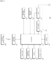
- FIG. 2 is an internal block diagram of an image display apparatus of FIG. 1 .
- the image display apparatus 100 may include a broadcast receiver 105, an external device interface 130, a network interface 135, a storage 140, a user input interface 150, an input interface 160, a controller 170, a display 180, an audio output interface 185, and/or a power supply 190.
- the broadcast receiver 105 may include a tuner 110 and a demodulator 120.
- the image display apparatus 100 may include only the broadcast receiver 105 and the external device interface 130, among the broadcast receiver 105, the external device interface 130, and the network interface 135. That is, the image display apparatus 100 may not include the network interface 135.
- the tuner 110 may select a broadcast signal corresponding to a channel selected by a user or each of all pre-stored channels from among broadcast signals received through an antenna (not shown) or a cable (not shown).
- the tuner 110 may convert the selected broadcast signal into an intermediate frequency signal or a baseband video or audio signal.
- the tuner 110 may convert it into a digital IF (DIF) signal, whereas when the selected broadcast signal is an analog broadcast signal, the tuner 110 may convert it into an analog baseband video or audio signal (CVBS/SIF). That is, the tuner 110 may process the digital broadcast signal or the analog broadcast signal.
- the analog baseband video or audio signal (CVBS/SIF) output from the tuner 110 may be directly input to the controller 170.
- the tuner 110 may sequentially select broadcast signals corresponding to all broadcast channels stored through a channel memory function from among the received broadcast signals, and then may convert them into intermediate frequency signals or baseband video or audio signals.
- the tuner 110 may include a plurality of tuners to receive broadcast signals of a plurality of channels.
- the tuner 110 may be configured as a single tuner capable of simultaneously receiving broadcast signals of a plurality of channels.
- the demodulator 120 may receive and demodulate the digital IF (DIF) signal converted by the tuner 110.
- DIF digital IF
- the demodulator 120 may perform demodulation and channel decoding to output a stream signal TS.
- the stream signal TS may be a signal in which a video signal, an audio signal, and a data signal are multiplexed.
- the stream signal output from the demodulator 120 may be input to the controller 170.
- the controller 170 may perform demultiplexing and video/audio signal processing, and then may output an image and sound through the display 180 and the audio output interface 185, respectively.
- the external device interface 130 may transmit and receive data to and from an external device connected thereto.
- the external device interface 130 may include an A/V input and output interface (not shown).
- the external device interface 130 may be connected to an external device such as a Digital Versatile Disc (DVD), a Blu-ray disc, a game console, a camera, a camcorder, a computer (e.g., a laptop computer), or a set-top box in a wired or wireless manner, and may perform input/output operations with the external device.
- DVD Digital Versatile Disc
- Blu-ray disc Blu-ray disc
- game console e.g., a camcorder
- a computer e.g., a laptop computer
- set-top box in a wired or wireless manner
- the external device interface 130 may establish a communication network with various remote control devices 200 as shown in FIG. 1 , so as to receive a control signal related to the operation of the image display apparatus 100 from the remote control device 200 or transmit data related to the operation of the image display apparatus 100 to the remote control device 200.
- the A/V input and output interface may receive video and audio signals from an external device.
- the A/V input and output interface may include an Ethernet terminal, a USB terminal, a Composite Video Banking Sync (CVBS) terminal, a component terminal, an S-video terminal (analog), a Digital Visual Interface (DVI) terminal, a High-Definition Multimedia Interface (HDMI) terminal, a Mobile High-definition Link (MHL) terminal, a RGB terminal, a D-SUB terminal, an IEEE 1394 terminal, an SPDIF terminal, a liquid HD terminal, etc.
- Digital signals input through these terminals may be transmitted to the controller 170.
- analog signals input through the CVBS terminal and the S-video terminal may be converted by an analog-digital converter (not shown) to be transmitted to the controller 170.
- the external device interface 130 may include a wireless communication interface (not shown) for short-range wireless communication with another electronic device.
- the wireless communication interface may allow the external device interface 130 to exchange data with a nearby mobile terminal nearby.
- the external device interface 130 may receive device information, information about an application being executed, and an application image from the mobile terminal in a mirroring mode.
- the external device interface 130 may use Bluetooth, Radio Frequency Identification (RFID), infrared Data Association (IrDA), Ultra-Wideband (UWB), ZigBee, or the like to perform short-range wireless communication.
- RFID Radio Frequency Identification
- IrDA infrared Data Association
- UWB Ultra-Wideband
- ZigBee ZigBee
- the network interface 135 may provide an interface for connecting the image display apparatus 100 to a wired/wireless network including an internet network.
- the network interface 135 may include a communication module (not shown) for connection to a wired/wireless network.
- the network interface 135 may include a communication module for Wireless LAN (WLAN) (Wi-Fi), Wireless Broadband (WiBro), Worldwide Interoperability for Microwave Access (WiMAX), High Speed Downlink Packet Access (HSDPA), etc.
- WLAN Wireless LAN
- WiBro Wireless Broadband
- WiMAX Worldwide Interoperability for Microwave Access
- HSDPA High Speed Downlink Packet Access
- the network interface 135 may transmit or receive data with another user or another electronic device through a connected network or another network linked to the connected network.
- the network interface 135 may receive web content or data provided by a content provider or a network operator. That is, the network interface 135 may receive, through a network, content such as movies, advertisements, games, VOD files, and broadcast signals provided by a content provider or a network operator, and information related thereto.
- content such as movies, advertisements, games, VOD files, and broadcast signals provided by a content provider or a network operator, and information related thereto.
- the network interface 135 may receive update information and update files of a firmware provided by a network operator, and may transmit data over Internet or to a content provider or a network provider.
- the network interface 135 may select and receive, through a network, a desired application from among applications open to the public.
- the storage 140 may store a program for processing and controlling each signal in the controller 170, or may store a signal-processed video, audio, or data signal.
- the storage 140 may store applications designed to perform various tasks that can be processed by the controller 170, and may selectively provide some of the stored applications in response to a request from the controller 170.
- the program stored in the storage 140 is not limited to any specific program, so long as it is capable of being executed by the controller 170.
- the storage 140 may temporally store a video, audio or data signal received from an external device through the external device interface 130.
- the storage 140 may store information about predetermined broadcast channels through a channel memory function such as channel map.
- FIG. 2 illustrates that the storage 140 is provided separately from the controller 170, the present disclosure is not limited thereto.
- the storage 140 may be included in the controller 170.
- the storage 140 may include at least one of volatile memory (e.g., DRAM, SRAM, SDRAM, etc.) or non-volatile memory (e.g., flash memory, hard disk drive (HDD), solid-state drive (SSD), etc.). In various embodiments of the present disclosure, the storage 140 and the memory may be used interchangeably.
- volatile memory e.g., DRAM, SRAM, SDRAM, etc.
- non-volatile memory e.g., flash memory, hard disk drive (HDD), solid-state drive (SSD), etc.
- HDD hard disk drive
- SSD solid-state drive
- the user input interface 150 may deliver a signal input by a user to the controller 170 or may deliver a signal from the controller 170 to the user.
- the user input interface 150 may transmit/receive a user input signal, such as power on/off, channel selection, or screen setting, to/from the remote control device 200, may transmit a user input signal input through a local key (not shown), such as a power key, a channel key, a volume key, or a setting key, to the controller 170, may transmit a user input signal input from a sensor (not shown) configured to sense a user's gesture, or may transmit a signal from the controller 170 to the sensor.
- a local key such as a power key, a channel key, a volume key, or a setting key
- the input interface 160 may be provided on one side of a body of the image display apparatus 100.
- the input interface 160 may include a touch pad, a physical button, etc.
- the input interface 160 may receive various user commands related to the operation of the image display apparatus 100, and may transmit a control signal corresponding to the received command to the controller 170.
- the input interface 160 may include at least one microphone (not shown), and may receive a user's voice through the microphone.
- the controller 170 may include at least one processor, and may control the overall operation of the image display apparatus 100 using the processor included therein.
- the processor may be a general processor such as a central processing unit (CPU).
- the processor may be a dedicated device such as an application-specific integrated circuit (ASIC), or may be any of other hardware-based processors.
- ASIC application-specific integrated circuit
- the controller 170 may demultiplex a stream input through the tuner 110, the demodulator 120, the external device interface 130, or the network interface 135, or may process demultiplexed signals to generate and output a signal for video or audio output.
- the display 100 may include a display panel (not shown) including a plurality of pixels.
- the plurality of pixels provided in the display panel may include RGB subpixels.
- the plurality of pixels provided in the display panel may include RGBWsubpixels.
- the display 180 may convert an image signal, a data signal, an OSD signal or a control signal processed by the controller 170 to generate a signal for driving the plurality of pixels.
- the display 180 may be implemented as a plasma display panel (PDP) display, a liquid crystal display (LCD) display, an organic light-emitting diode (OLED) display or a flexible display, or may be implemented as a three-dimensional (3D) display.
- the 3D display 180 may be classified as a non-glasses type and a glasses type.
- the display 180 may be configured as a touch screen, and thus may be used not only as an output device but also as an input device.
- the audio output interface 185 may receive an audio signal processed by the controller 170 to output sound.
- the image signal processed by the controller 170 may be input to the display 180, allowing an image corresponding to the received image signal to be displayed.
- the image signal processed by the controller 170 may be input to an external output device through the external device interface 130.
- the audio signal processed by the controller 170 may be output in the form of sound through the audio output interface 185.
- the audio signal processed by the controller 170 may be input to the external output device through the external device interface 130.
- the controller 170 may include a demultiplexer, an image processing unit, and the like. This will be described later with reference to FIG. 3 .
- the controller 170 may control the overall operation of the image display apparatus 100. For example, the controller 170 may control the tuner 110 to tune a broadcast signal corresponding to a channel selected by a user or a pre-stored channel.
- controller 170 may control the image display apparatus 100 in response to a command input by the user through the user input interface 150 or according to an internal program.
- the controller 170 may control the display 180 to display an image.
- the image displayed on the display 180 may be a still image or a moving image, and may be a 2D image or a 3D image.
- the controller 170 may control such that a predetermined 2D object is displayed in the image displayed on the display 180.
- the object may be at least one of a connected web screen (e.g., newspaper, magazine, etc.), an electronic program guide (EPG), various menus, a widget, an icon, a still image, a moving image, and a text.
- EPG electronic program guide
- the image display apparatus 100 may further include a photographing unit (not shown).
- the photographing unit may photograph a user.
- the photographing unit may be configured as one camera, but is not limited thereto.
- the photographing unit may be configured as a plurality of cameras.
- the photographing unit may be embedded in the image display apparatus 100 at an upper portion of the display 180 or may be separately disposed. Information of an image captured by the photographing unit may be input to the controller 170.
- the controller 170 may identify the location of a user based on an image captured by the photographing unit. For example, the controller 170 may identify a distance (z-axis coordinate) between the user and the image display apparatus 100. In addition, the controller 170 may determine the x-axis coordinate and the y-axis coordinate in the display 180 that correspond to the location of the user.
- the controller 170 may detect a user's gesture based on an image captured by the photographing unit, each of signals sensed by the sensor, or a combination thereof.
- the power supply 190 may include a converter (not shown) for converting alternating-current (AC) power to direct-current (DC) power, and a DC/DC converter (not shown) for converting the level of DC power.
- the remote control device 200 may transmit a user input to the user input interface 150.
- the remote control device 200 may use Bluetooth, Radio Frequency (RF) communication, Infrared Radiation (IR) communication, Ultra-Wideband (UWB), ZigBee, or the like.
- the remote control device 200 may receive a video, audio or data signal output from the user input interface 150, and may output the received signal in the form of an image or sound.
- the image display apparatus 100 described above may be a digital broadcast receiver capable of receiving a fixed or mobile digital broadcast.
- FIG. 2 the block diagram of the image display apparatus 100 shown in FIG. 2 is merely one example of the present disclosure. Respective components of the block diagram may be combined, added, or omitted depending on the specification of an image display apparatus 100 that is actually implemented.
- two or more components may be combined into a single component, or one component may be subdivided into two or more components as necessary.
- the function performed in each block is illustrative only, and a specific operation or configuration thereof does not limit the scope of the present disclosure.
- FIG. 3 is an internal block diagram of a controller of FIG. 2 .
- the controller 170 may include a demultiplexer 310, an audio processing unit 315, an image processing unit 320, a processor 330, an OSD generator 340, a mixer 345, a frame rate converter 350, and/or a formatter 360.
- the controller 170 may further include a data processing unit (not shown).
- the demultiplexer 310 may demultiplex an input stream.
- the demultiplexer 310 may demultiplex an MPEG-2 TS into an image signal, an audio signal, and a data signal.
- the stream signal input to the demultiplexer 310 may be a stream signal output from the tuner 110, the demodulator 120, or the external device interface 130.
- the audio processing unit 315 may perform audio signal processing on an audio signal demultiplexed by the demultiplexer 310 or an audio signal directly input from the external device interface 130 or the network interface 135. To this end, the audio processing unit 315 may include various decoders.
- the audio processing unit 315 may include a mixer to mix audio signals decoded by various decoders, e.g., audio signals of various channels.
- the audio signal mixed by the mixer may be transmitted to the audio output interface 185.
- the audio processing unit 315 may process the adjustment of bass, treble, volume, or may automatically process a sound filed signal.
- the audio processing unit 315 may adjust at least one of a gain or a phase for each frequency band of an audio signal.
- the processed audio signal may be output through the audio output interface 185 in the form of sound.
- the audio output interface 185 may consist of a digital amplifier (D-Amp) and/or a speaker. This will be described later with reference to FIG. 4 .
- Th image processing unit 320 may perform image processing on the demultiplexed image signal.
- the image processing unit 320 may include a video decoder 325 and a scaler 335.
- the video decoder 325 may decode the demultiplexed image signal, and the scaler 335 may perform scaling to allow the resolution of the decoded image signal to be displayed on the display 180.
- the video decoder 325 may include decoders of different standards.
- the video decoder 325 may include an MPEG-2 decoder, an H.264 decoder, a 3D video decoder for a color image and a depth image, a decoder for multi-view images, and the like.
- the processor 330 may control the overall operation of the image display apparatus 100 or the controller 170. For example, the processor 330 may control the tuner 110 to tune a broadcast corresponding to a channel selected by a user or a pre-stored channel.
- the processor 330 may control the image display apparatus 100 according to a user command input through the user input inface 150 or according to an internal program.
- the processor 330 may control data transmission with the network interface 135 or the external device interface 130.
- the processor 330 may control the operation of the demultiplexer 310, the image processing unit 320, and the OSD generator 340 in the controller 170.
- the OSD generator 340 may generate an OSD signal autonomously or according to a user input.
- the OSD generator 340 may generate a signal for displaying various kinds of information in the form of a graphic image or a text on the screen of the display 180, based on a user input signal input through the input interface 160.
- the generated OSD signal may include various data such as a user interface screen of the image display apparatus 100, various menu screens, widgets, icons, and the like.
- the generated OSD signal may include a 2D object or a 3D object.
- the OSD generator 340 may generate a pointer that can be displayed on the display 180 based on a pointing signal received from the remote control device 200.
- the OSD generator 340 may include a pointing signal processing unit (not shown) to generate a pointer.
- the pointing signal processing unit (not shown) may be provided separately instead of being provided in the OSD generator 340.
- the mixer 345 may mix an OSD signal generated by the OSD generator 340 and a decoded image signal processed by the image processing unit 320.
- the mixed image signal may be provided to the frame rate converter 350.
- the frame rate converter (FRC) 350 may convert the frame rate of an input image. Alternatively, the FRC 350 may output an input image without any frame rate conversion.
- the formatter 360 may arrange a left-eye image frame and a right-eye image frame of the frame rate converted 3D image.
- the formatter 360 may output a synchronization signal Vsync to open the left eye glass or right eye glass of a 3D viewing device (not shown).
- the formatter 360 may change the format of an input image signal to an image signal suitable for being displayed on the display 180.
- the formatter 360 may change the format of a 3D image signal.
- the formatter 360 may change the format of a 3D image signal to one of various 3D formats such as a side-by-side format, a top/down format, a frame sequential format, an interlaced format, a checker box format.
- the formatter 360 may convert a 2D image signal into a 3D image signal.
- the formatter 360 may detect an edge or a selectable object in a 2D image signal, and separate an object defined by the detected edge or the selectable object into a 3D image signal.
- the generated 3D image signal may be separated into a left-eye image signal L and a right-eye image signal R to be aligned.
- a 3D processor (not shown) for processing a 3-dimensional (3D) effect signal may be further provided after the formatter 360.
- a 3D processor may perform brightness, tint, and color adjustment to improve 3D effects.
- the 3D processor may perform signal processing to make the near clear and the far blurry.
- the function of the 3D processor may be integrated into the formatter 360 or the image processing unit 320.
- the data processing unit (not shown) in the controller 170 may perform data processing of a demultiplexed data signal.
- the data processing unit may decode it.
- the encoded data signal may be electronic program guide (EPG) information including broadcasting information such as the start time and end time of broadcast programs aired on each channel.
- EPG electronic program guide
- FIG. 3 the block diagram of the controller 170 shown in FIG. 3 is merely one example of the present disclosure. Respective components of the block diagram may be combined, added, or omitted depending on the specification of a controller 170 that is actually implemented.
- the audio processing unit 315, the frame rate converter 350, and the formatter 360 may, instead of being provided in the controller 170, be respectively provided separately from the controller 170 or may be provided as a single module separately from the controller 170.
- FIG. 4 illustrates a control method of a remote control device of FIG. 2 .
- a pointer 205 corresponding to the remote control device 200 may be displayed on the display 180 of the image display apparatus 100.
- a user may move the remote control device 200 up and down, left and right, and back and forth, or rotate it.
- the pointer 205 displayed on the display 180 of the image display apparatus 100 may correspond to movement of the remote control device 200.
- Such a remote control device 200 may be referred to as a spatial remote controller or a 3D pointing device, since the remote control device 200 allows a corresponding pointer 205 to be moved and displayed according to movement in a 3D space as shown in the drawing.
- the pointer 205 displayed on the display 180 of the image display apparatus 100 may be moved to the left in response to the movement of the remote control device 200.
- Information regarding the movement of the remote control device 200 may be transmitted to the image display apparatus 100.
- the image display apparatus 100 may calculate the coordinates of the pointer 205 based on the information regarding the movement of the remote control device 200.
- the image display apparatus 100 may display the pointer 205 to correspond to the calculated coordinates.
- a user may move the remote control device 200 away from the display 180 while pressing a specific button on the remote control device 200. Then, a selection area in the display 180 corresponding to the pointer 205 may be zoomed in and displayed in an enlarged size.
- a selection area in the display 180 corresponding to the pointer 205 may be zoomed out and displayed in a reduced size.
- a selection area may be zoomed out, and when the remote control device 200 is moved closer to the display 180, a selection area may be zoomed in.
- up and down and left and right movement of the remote control device 200 may not be recognized while a specific button in the remote control device 200 is pressed. That is, when the remote control device 200 is moved away from or closer to the display 180, up, down, left and right movement of the remote control device 200 may not be recognized, and only forward and backward movement of the remote control device 200 may be recognized. While the specific button in the remote control device 200 is not pressed, only up, down, left and right movement of the remote control device 200 may be recognized, and only the pointer 205 may be moved accordingly.
- the moving speed or moving direction of the pointer 205 may correspond to the moving speed or moving direction of the remote control device 200.
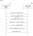
- FIG. 5 is a flowchart for explaining a function of sharing a screen between image display apparatuses, in accordance with an embodiment of the present disclosure.
- a first image display apparatus 100a may be referred to as a Wi-Fi display (WFD) source, a source device, or the like, which provides content.
- a second image display apparatus 100b may be referred to as a WFD sink, a sink device, or the like, which receives and renders content.
- WFD Wi-Fi display
- the first image display apparatus 100a and the second image display apparatus 100b may discover each other's presence through WFD device discovery.
- the first image display apparatus 100a and the second image display apparatus 100b may recognize each other's presence through a probe request frame and a probe response frame, which contain a WFD information element (WFD IE).
- WFD IE may include basic information, such as a device type and a device state (or status), to establish an optimal connection between devices.
- the second image display apparatus 100b may transmit a probe response frame including its WFD IE in response to receiving the probe request frame.
- two or more Wi-Fi transceivers may logically operate in one physical device.
- the first image display apparatus 100a and the second image display apparatus 100b may discover the service capability of each other. For example, when the first image display apparatus 100a transmits a service discovery request frame that includes WFD capability as an information sub-element, the second image display apparatus 100b may transmit, in response thereto, a service discovery response frame that includes its WFD capability as an information sub-element.
- the first image display apparatus 100a or the second image display apparatus 100b may select a peer WFD device for WFD connection setup.
- a peer WFD device for processing WFD connection setup may be selected by a user input, or a peer WFD device for processing WFD connection setup may be automatically selected according to a policy.
- the first image display apparatus 100a and the second image display apparatus 100b may select a WFD connection setup method with the selected peer WFD device.
- the first image display apparatus 100a and the second image display apparatus 100b may establish a WFD connection using a connectivity scheme of one of Wi-Fi P2P and Tunneled Direct Link Setup (TDLS).
- the first image display apparatus 100a and the second image display apparatus 100b may determine a connectivity scheme based on preferred connectivity information and an associated BSSID sub-element delivered along with a WFD IE.
- the first image display apparatus 100a and the second image display apparatus 100b may perform WFD capability negotiation.
- the first image display apparatus 100a and the second image display apparatus 100b may exchange a message using a Real-Time Streaming Protocol (RTSP) to determine a parameter set defining an audio/video payload during a WFD session.
- RTSP Real-Time Streaming Protocol
- the first image display apparatus 100a and the second image display apparatus 100b may exchange their apparatus information.
- the first image display apparatus 100a may request the second image display apparatus 100b to transmit apparatus information.
- the second image display apparatus 100b may transmit its apparatus information to the first image display apparatus 100a.
- the apparatus information of the second image display apparatus 100b may include image information such as a resolution and a video codec supported by the second image display apparatus 100b.
- the apparatus information of the second image display apparatus 100b may include audio information such as a sound field effect, an audio channel and an audio codec supported by the second image display apparatus 100b.
- the first image display apparatus 100a may transmit a necessary request message to the second display apparatus 100b by using the RTSP protocol. For example, based on the image information received from the second image display apparatus 100b, the first image display apparatus 100a may transmit, to the second image display apparatus 100b by using the RTSP protocol, a message indicating that an image of content corresponding to a specific resolution is to be delivered. For example, based on the audio information received from the second image display apparatus 100b, the first image display apparatus 100a may transmit, to the second image display apparatus 100b by using the RTSP protocol, a message indicating that audio of content with a specific sound field effect is to be delivered.
- the second image display apparatus 100b may transmit a response message through the RTSP protocol. Meanwhile, the operation S609 and the operation S611 may be included in the operation S607 for WFD capability negotiation.
- a WFD session (or a Miracast session) may be established between the first image display apparatus 100a and the second image display apparatus 100b.
- a WFD session (or a Miracast session) may be established between the first image display apparatus 100a and the second image display apparatus 100b.
- an image signal and/or an audio signal may be streamed to the second image display apparatus 100b from the first image display apparatus 100a.
- FIG. 6 is a flowchart illustrating a method of operating a source device, in accordance with an embodiment of the present disclosure. The same description as provided with reference to FIG. 5 will be omitted.
- the source device 100a may perform communication connection with the sink device 100b.
- the source device 100a and the sink device 100b may perform a negotiation procedure for Miracast connection.
- the source device 100a may receive the device information from the sink device 100b.
- the source device 100a may receive, from the sink device 100b, device information that includes resolution information, video codec information, audio codec information and sound field effect information supported by the sink device 100b, audio channel information of the sink device 100b, operation mode information, manufacturer information, model name information, user input back channel (UIBC) information, etc.
- device information that includes resolution information, video codec information, audio codec information and sound field effect information supported by the sink device 100b, audio channel information of the sink device 100b, operation mode information, manufacturer information, model name information, user input back channel (UIBC) information, etc.
- UIBC user input back channel
- the source device 100a may determine whether a specification in association with audio signal processing satisfies a predetermined criterion. For example, the source device 100a may determine whether it is possible for the sink device 100b to process an audio signal to correspond to the source device 100a. When it is possible for the sink device 100b to process an audio signal in correspondence to the source device 100a, the predetermined criterion may be satisfied.
- the source device 100a may process an audio signal so that a sound field effect is applied according to a sound equalizer setting corresponding to a genre of content. For example, the source device 100a may determine a genre of the content provided to the sink device 100 by checking metadata of the content, analyzing an image frame based on an algorithm using machine learning, or the like. In this case, the source device 100a may determine a genre of the content to determine whether the sink device 100b is capable of processing an audio signal so that a sound filed effect is applied according to a sound equalizer setting corresponding to the genre of the content.
- the source device 100a may process an audio signal so that a predetermined sound effect for stereophonic sound (e.g., Dolby Atmos) is applied using a predetermined audio codec. In this case, the source device 100a may determine whether the sink device 100b is capable of processing the audio signal so that the predetermined sound effect for stereophonic sound is applied through the predetermined audio codec.
- a predetermined sound effect for stereophonic sound e.g., Dolby Atmos
- the source device 100a may process an audio signal corresponding to first audio data for content to correspond to the sink device 100b. For example, when it is not possible for the sink device 100b to process an audio signal according to a genre of content, the source device 100a may determine a genre of the content and process the audio signal according to a sound equalizer setting corresponding to the determined genre. For example, when it is not possible for the sink device 100b to process an audio signal by applying a predetermined sound effect for stereophonic sound (e.g., Dolby Atmos), the source device 100a may process the audio signal by applying a predetermined sound effect.
- a predetermined sound effect for stereophonic sound e.g., Dolby Atmos
- the source device 100a may process an audio signal based on audio channel information of the sink device 100b. For example, when an audio signal corresponding to first audio data is an audio signal of channel 5.1, and the sink device 100b includes a speaker of channel 2, the source device 100a may down-mix the audio signal of channel 5.1 to correspond to channel 2. In addition, the source device 100a may process the audio signal by applying a sound field effect to correspond to channel 2.
- the source device 100a may generate second audio data corresponding to the processed audio signal.
- the source device 100a may transmit audio data to the sink device 100b. For example, when the specification in association with audio signal processing satisfies the predetermined criterion, the source device 100a may transmit the first audio data to the sink device 100b. For example, when the specification in association with audio signal processing does not satisfy the predetermined criterion, the source device 100a may transmit the second audio data to the sink device 100b.
- the source device 100a and the sink device 100b may perform Miracast connection while the source device 100a outputs a screen on which predetermined content is displayed.
- the source device 100a may receive device information of the sink device 100b in a negotiation procedure for the Miracast connection.
- the source device 100a may transmit image data for the predetermined content.
- the source device 100a may transmit image data for the predetermined content corresponding to a resolution of the sink device 100b to the sink device 100b.
- the sink device 100b may output a screen on which the predetermined content is displayed.
- the source device 100a may transmit audio data for the predetermined content to the sink device 100b. Based on the audio data received from the source device 100a, the sink device 100b may output audio for the predetermined content.
- FIGS. 9 and 10 are flowcharts for explaining operations of image display apparatuses according to a specification of a sink device, in accordance with an embodiment of the present disclosure.
- the source device 100a and the sink device 100b may perform Miracast connection.
- the source device 100a may receive device information of the sink device 100b in a negotiation procedure for the Miracast connection.
- the source device 100a may process an audio signal corresponding to first audio data for predetermined content in correspondence to the sink device 100b.
- the source device 100 may determine a genre of the content and process the audio signal so that a sound field effect is applied according to a sound equalizer setting corresponding to the determined genre.
- the source device 100a may process the audio signal so that a predetermined sound effect for stereophonic sound (e.g., Dolby Atmos) is applied using a predetermined audio codec.
- a predetermined sound effect for stereophonic sound e.g., Dolby Atmos
- the source device 100a may generate second audio data corresponding to the processed audio signal.
- the source device 100a may transmit the generated second audio data to the sink device 100b.
- the sink device 100b may output audio of the predetermined content based on the second audio data received from the source device 100a.
- the sink device 100b may process the second audio data and output the audio signal as is, which is processed, by the source device 100a, in such a manner that a sound field effect is applied.
- the source device 100a may provide an optimized audio signal to the sink device 100b, allowing the sink device 100b to output audio optimized for the predetermined content.
- the source device 100a and the sink device 100b may perform Miracast connection.
- the source device 100a may receive device information of the sink device 100b in a negotiation procedure for the Miracast connection.
- the source device 100a may transmit first audio data for predetermined content to the sink device 100b.
- the sink device 100b may process an audio signal corresponding to the first audio data for the predetermined content. For example, the sink device 100b may determine a genre of the content and process the audio signal so that a sound field effect is applied according to a sound equalizer setting corresponding to the determined genre. For example, the sink device 100b may process the audio signal so that a predetermined sound effect for stereophonic sound (e.g., Dolby Atmos) is applied using a predetermined audio codec.
- a predetermined sound effect for stereophonic sound e.g., Dolby Atmos
- the sink device 100b may output audio of the predetermined content according to the processed audio signal.
- FIG. 11 is a flowchart illustrating a method of operating a source device, in accordance with another embodiment of the present disclosure. The same description as provided with reference to FIG. 5 and FIG. 6 will be omitted.
- the source device 100a may perform communication connection with the sink device 100b.
- the source device 100a and the sink device 100b may perform a negotiation procedure for Miracast connection.
- the source device 100a may request the sink device 100b to transmit device information.
- the source device 100a may determine an output gain of the sink device 100b corresponding to preset volume. For example, based on volume information of the source device 100a, power information for audio output of the source device 100a and/or power information for audio output of the sink device 100b, the source device 100a may determine an output gain of the sink device 100b corresponding to the preset volume. Meanwhile, the source device 100a may include a gain table for the level of volume information of the source device 100a and power information for audio output of the sink device 100b. In this case, the source device 100a may determine, based on the gain table, a gain corresponding to the volume information of the source device 100a and the power information for audio output of the sink device 100b as an output gain of the sink device 110b.
- the source device 100a may determine whether it is possible for the sink device 100b to process an audio signal to correspond to the source device 100a.
- the source device 100a may process an audio signal corresponding to first audio data for content in correspondence to the sink device 100b.
- the source device 100a may generate second audio data corresponding to the processed audio signal.
- the source device 100a may transmit audio data to the sink device 100b.
- the source device 100a may transmit data for the output gain of the sink device 110b to the sink device 100b.
- the source device 100a may transmit the first audio data to the sink device 100b.
- the source device 100a may transmit the second audio data to the sink device 100b.
- the source device 100a may transmit its volume information and power information for audio output to the sink device 100b.
- the sink device 100b may determine an output gain of the sink device 100b corresponding to preset volume to output audio.
- the external device 100b when sharing a screen with an external apparatus or device 100b, it is possible to allow the external device 100b to output high-quality audio compared to a specification of the external device 100b.
- an image display apparatus 100 includes: a display; a network interface configured to communicate with an external device; and a controller.
- the controller may be configured to: obtain device information from the external device; based on the obtained device information, determine whether a specification of the external device in association with audio signal processing satisfies a predetermined criterion; based on a determination that the specification of the external device does not satisfy the predetermined criterion, transmit first audio data for predetermined content being displayed through the display; based on a determination that the specification of the external device does not satisfy the predetermined criterion, process an audio signal corresponding to the first audio data according to the specification of the external device; and generate second audio data corresponding to the processed audio signal to transmit the second audio data to the external device.
- the device information may include at least one of a sound field effect provided by the external device, an audio codec supported by the external device, and an audio channel of the external device.
- the controller may be configured to obtain the device information from the external device.
- the predetermined function may be a function of sharing the screen on the external device via Miracast connection.
- the controller may be configured to obtain the device information from the external device in a negotiation procedure for the Miracast connection.
- the controller may be configured to: when audio signal processing in association with a predetermined sound field effect is not enabled by the external device, determine that the specification of the external device does not satisfy the predetermined criterion; and in response to the predetermined sound field effect, process the audio signal according to a preset setting of a sound equalizer.
- the controller may be configured to: when audio signal processing using a predetermined audio codec is not enabled by the external device, determine that the specification of the external device does not satisfy the predetermined criterion; and process the audio signal using the predetermined audio codec.
- the device information may include power information for audio output of the external device.
- the controller may be configured to: determine, based on preset volume information and the power information of the external device, an output gain of the external device; and transmit data for the determined output gain to the external device.
- the controller may be configured to transmit preset volume information and power information for audio output of the image display apparatus to the external device.
- the method of operating the image display apparatus may be implemented as processor-readable codes in a processor-readable recording medium.
- the processor-readable recording medium may be any type of recording device capable of storing data readable by a processor. Examples of the processor-readable recording medium may include a ROM, a RAM, a CD-ROM, a magnetic tape, a floppy disc, and an optical data storage device. Also, the processor-readable recording medium may be implemented as a carrier wave (e.g., data transmission over the Internet).
- the processor-readable recording medium may be distributed to a computer system connected via a network so that the processor-readable codes may be saved and executed in a distributed manner.
Landscapes
- Engineering & Computer Science (AREA)
- Multimedia (AREA)
- Signal Processing (AREA)
- Theoretical Computer Science (AREA)
- General Engineering & Computer Science (AREA)
- Human Computer Interaction (AREA)
- Physics & Mathematics (AREA)
- General Physics & Mathematics (AREA)
- Audiology, Speech & Language Pathology (AREA)
- General Health & Medical Sciences (AREA)
- Health & Medical Sciences (AREA)
- Computer Networks & Wireless Communication (AREA)
- Two-Way Televisions, Distribution Of Moving Picture Or The Like (AREA)
Abstract
An image display apparatus (100) according to an embodiment of the present disclosure includes: a display; a network interface configured to communicate with an external device; and a controller, the controller being configured to: obtain device information from the external device; based on the obtained device information, determine whether a specification of the external device in association with audio signal processing satisfies a predetermined criterion; based on a determination that the specification of the external device does not satisfy the predetermined criterion, transmit first audio data for predetermined content being displayed through the display; based on a determination that the specification of the external device does not satisfy the predetermined criterion, process an audio signal corresponding to the first audio data according to the specification of the external device; and generate second audio data corresponding to the processed audio signal to transmit the second audio data to the external device.
Description
- The present disclosure relates to an image display apparatus.
- An image display apparatus (or device) has a function of displaying an image to a user. Examples of the image display apparatus may include a television (TV), a monitor, a notebook computer, and the like having a Liquid Crystal Display (LCD) using liquid crystals or an Organic Light-Emitting Diode (OLED) display using OLEDs.
- Such an image display apparatus may transceive data with various electronic devices in a wired/wireless manner. Recently, there has been increased use of screen sharing technology that allows a user to share a screen of an image display apparatus currently being used by the user with another display apparatus. Such a screen sharing function (or service) between a plurality of image display apparatuses is used or provided under various names, including Miracast, screen mirroring, airplay, wireless display (WiDi), etc.
- Meanwhile, when a screen-sharing function, such as Miracast, is used between image display apparatuses or devices, it is common for a transmitting side device (i.e., the sender) to obtain information on a specification associated with image output of a receiving side device (i.e., the receiver), such as resolution, a supported codec, and the like, and to provide an optimized image signal to the receiving side device. However, unlike an image signal, an audio signal is transmitted by the transmitting side device regardless of the specification of the receiving side device. In this case, due to a difference between the specifications of the receiving side device and the transmitting side device, a difference occurs between the quality of audio output from the receiving side device and the quality of audio output from the transmitting side device.
- It is an objective of the present disclosure to solve the above and other problems.
- It is another objective of the present disclosure to provide, when sharing a screen with an external device, an image display apparatus that can provide an optimized audio signal to the external device based on audio output information of the external device.
- It is yet another objective of the present disclosure to provide, when sharing a screen with an external device, an image display apparatus that can be operated such that high-quality audio is output from the external device compared to a specification of the external device.
- It is yet another objective of the present disclosure to provide, when sharing a screen with an external device, an image display apparatus that can ensure the continuity of settings associated with audio output.
- According to an aspect of the subject matter described in this application, an image display apparatus includes: a display; a network interface configured to communicate with an external device; and a controller, the controller being configured to: obtain device information from the external device; based on the obtained device information, determine whether a specification of the external device in association with audio signal processing satisfies a predetermined criterion; based on a determination that the specification of the external device does not satisfy the predetermined criterion, transmit first audio data for predetermined content being displayed through the display; based on a determination that the specification of the external device does not satisfy the predetermined criterion, process an audio signal corresponding to the first audio data according to the specification of the external device; and generate second audio data corresponding to the processed audio signal to transmit the second audio data to the external device.
- An image display apparatus according to the present disclosure has the following effects.
- According to at least one of the embodiments of the present disclosure, when sharing a screen with an external device, it is possible to provide an optimized audio signal to the external device based on audio output information of the external device.
- According to at least one of the embodiments of the present disclosure, when sharing a screen with an external device, it is possible to allow the external device to output high-quality audio compared to a specification of the external device.
- According to at least one of the embodiments of the present disclosure, when sharing a screen with an external device, it is possible to ensure the continuity of settings associated with audio output.
- Further scope of applicability of the present disclosure will become apparent from the following detailed description. However, it should be understood that the detailed description and specific embodiments such as preferred embodiments of the present disclosure are given by way of example only, since various changes and modifications within the idea and scope of the present disclosure may be clearly understood by those skilled in the art.
-
-
FIG. 1 is a diagram illustrating an image display system, in accordance with an embodiment of the present disclosure. -
FIG. 2 is an internal block diagram of an image display apparatus, in accordance with an embodiment of the present disclosure. -
FIG. 3 is an internal block diagram of a controller, in accordance with an embodiment of the present disclosure. -
FIG. 4 is a diagram illustrating a control method of a remote control device, in accordance with an embodiment of the present disclosure. -
FIG. 5 is a flowchart for explaining a function of sharing a screen between image display apparatuses, in accordance with an embodiment of the present disclosure. -
FIG. 6 is a flowchart illustrating a method of operating a source device, in accordance with an embodiment of the present disclosure. -
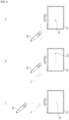
FIGS. 7 and8 are diagrams for explaining a function of sharing a screen between image display apparatuses, in accordance with an embodiment of the present disclosure. -
FIGS. 9 and 10 are flowcharts for explaining operations of image display apparatuses according to the specification of a sink device, in accordance with an embodiment of the present disclosure. -
FIG. 11 is a flowchart illustrating a method of operating a source device, in accordance with another embodiment of the present disclosure. - Description will now be given in detail according to exemplary embodiments disclosed herein, with reference to the accompanying drawings. For the sake of brief description with reference to the drawings, the same or equivalent components may be denoted by the same reference numbers, and description thereof will not be repeated.
- In the following description, a suffix such as "module" and "unit" may be used to refer to elements or components. Use of such a suffix herein is merely intended to facilitate description of the specification, and the suffix itself is not intended to give any special meaning or function.
- In the present disclosure, that which is well known to one of ordinary skill in the relevant art has generally been omitted for the sake of brevity. The accompanying drawings are used to help easily understand the technical idea of the present disclosure and it should be understood that the idea of the present disclosure is not limited by the accompanying drawings. The idea of the present disclosure should be construed to extend to any alterations, equivalents, and substitutes besides the accompanying drawings.
- It will be understood that although the terms "first", "second", etc. may be used herein to describe various elements, these elements should not be limited by these terms. These terms are only used to distinguish one element from another.
-
FIG. 1 is a diagram illustrating an image display system, in accordance with an embodiment of the present disclosure. - Referring to
FIG. 1 , animage display system 10 may include a plurality ofimage display apparatuses 100a to 100d. Theimage display system 10 may include a relay device, i.e., an access point (AP) 20. - An
image display apparatus 100 may be an apparatus that processes and outputs an image. Theimage display apparatus 100 is not particularly limited, such as a TV, a notebook computer, a monitor, etc., as long as it can output a screen corresponding to an image signal. - The
image display apparatus 100 may receive a broadcast signal and signal-process the broadcast signal to output a signal-processed broadcast image. When theimage display apparatus 100 receives a broadcast signal, theimage display apparatus 100 may correspond to a broadcast receiver. - The
image display apparatus 100 may receive a broadcast signal wirelessly through an antenna, or may receive a broadcast signal in a wired manner through a cable. For example, theimage display apparatus 100 may receive a terrestrial broadcast signal, a satellite broadcast signal, a cable broadcast signal, an Internet Protocol Television (IPTV) broadcast signal, etc. - The AP 20 may communicate with the
image display apparatus 100. The AP 20 may be a networking sub-device that allows devices, connected to a local network provided by the AP 20, to transmit and receive data to and from each other, or to connect to a network such as the Internet. - The plurality of
image display apparatuses 100a to 100d may mutually transmit and receive data via a local network provided by the AP 20. The image display apparatuses may transmit and receive data to and from each other using short-range wireless communication such as Wireless Fidelity (Wi-Fi), Bluetooth, Bluetooth Low Energy (BLE), Zigbee, Near Field Communication (NFC), etc. -
FIG. 2 is an internal block diagram of an image display apparatus ofFIG. 1 . - Referring to
FIG. 2 , theimage display apparatus 100 may include abroadcast receiver 105, anexternal device interface 130, anetwork interface 135, astorage 140, auser input interface 150, aninput interface 160, acontroller 170, adisplay 180, anaudio output interface 185, and/or apower supply 190. - The
broadcast receiver 105 may include atuner 110 and ademodulator 120. - Meanwhile, unlike shown in the drawing, the
image display apparatus 100 may include only thebroadcast receiver 105 and theexternal device interface 130, among thebroadcast receiver 105, theexternal device interface 130, and thenetwork interface 135. That is, theimage display apparatus 100 may not include thenetwork interface 135. - The
tuner 110 may select a broadcast signal corresponding to a channel selected by a user or each of all pre-stored channels from among broadcast signals received through an antenna (not shown) or a cable (not shown). Thetuner 110 may convert the selected broadcast signal into an intermediate frequency signal or a baseband video or audio signal. - For example, when the selected broadcast signal is a digital broadcast signal, the
tuner 110 may convert it into a digital IF (DIF) signal, whereas when the selected broadcast signal is an analog broadcast signal, thetuner 110 may convert it into an analog baseband video or audio signal (CVBS/SIF). That is, thetuner 110 may process the digital broadcast signal or the analog broadcast signal. The analog baseband video or audio signal (CVBS/SIF) output from thetuner 110 may be directly input to thecontroller 170. - Meanwhile, the
tuner 110 may sequentially select broadcast signals corresponding to all broadcast channels stored through a channel memory function from among the received broadcast signals, and then may convert them into intermediate frequency signals or baseband video or audio signals. - Meanwhile, the
tuner 110 may include a plurality of tuners to receive broadcast signals of a plurality of channels. Alternatively, thetuner 110 may be configured as a single tuner capable of simultaneously receiving broadcast signals of a plurality of channels. - The
demodulator 120 may receive and demodulate the digital IF (DIF) signal converted by thetuner 110. - The
demodulator 120 may perform demodulation and channel decoding to output a stream signal TS. Here, the stream signal TS may be a signal in which a video signal, an audio signal, and a data signal are multiplexed. - The stream signal output from the
demodulator 120 may be input to thecontroller 170. Thecontroller 170 may perform demultiplexing and video/audio signal processing, and then may output an image and sound through thedisplay 180 and theaudio output interface 185, respectively. - The
external device interface 130 may transmit and receive data to and from an external device connected thereto. To this end, theexternal device interface 130 may include an A/V input and output interface (not shown). - The
external device interface 130 may be connected to an external device such as a Digital Versatile Disc (DVD), a Blu-ray disc, a game console, a camera, a camcorder, a computer (e.g., a laptop computer), or a set-top box in a wired or wireless manner, and may perform input/output operations with the external device. - In addition, the
external device interface 130 may establish a communication network with variousremote control devices 200 as shown inFIG. 1 , so as to receive a control signal related to the operation of theimage display apparatus 100 from theremote control device 200 or transmit data related to the operation of theimage display apparatus 100 to theremote control device 200. - The A/V input and output interface may receive video and audio signals from an external device. For example, the A/V input and output interface may include an Ethernet terminal, a USB terminal, a Composite Video Banking Sync (CVBS) terminal, a component terminal, an S-video terminal (analog), a Digital Visual Interface (DVI) terminal, a High-Definition Multimedia Interface (HDMI) terminal, a Mobile High-definition Link (MHL) terminal, a RGB terminal, a D-SUB terminal, an IEEE 1394 terminal, an SPDIF terminal, a liquid HD terminal, etc. Digital signals input through these terminals may be transmitted to the
controller 170. In this case, analog signals input through the CVBS terminal and the S-video terminal may be converted by an analog-digital converter (not shown) to be transmitted to thecontroller 170. - The
external device interface 130 may include a wireless communication interface (not shown) for short-range wireless communication with another electronic device. The wireless communication interface may allow theexternal device interface 130 to exchange data with a nearby mobile terminal nearby. For example, theexternal device interface 130 may receive device information, information about an application being executed, and an application image from the mobile terminal in a mirroring mode. - The
external device interface 130 may use Bluetooth, Radio Frequency Identification (RFID), infrared Data Association (IrDA), Ultra-Wideband (UWB), ZigBee, or the like to perform short-range wireless communication. - The
network interface 135 may provide an interface for connecting theimage display apparatus 100 to a wired/wireless network including an internet network. - The
network interface 135 may include a communication module (not shown) for connection to a wired/wireless network. For example, thenetwork interface 135 may include a communication module for Wireless LAN (WLAN) (Wi-Fi), Wireless Broadband (WiBro), Worldwide Interoperability for Microwave Access (WiMAX), High Speed Downlink Packet Access (HSDPA), etc. - The
network interface 135 may transmit or receive data with another user or another electronic device through a connected network or another network linked to the connected network. - The
network interface 135 may receive web content or data provided by a content provider or a network operator. That is, thenetwork interface 135 may receive, through a network, content such as movies, advertisements, games, VOD files, and broadcast signals provided by a content provider or a network operator, and information related thereto. - The
network interface 135 may receive update information and update files of a firmware provided by a network operator, and may transmit data over Internet or to a content provider or a network provider. - The
network interface 135 may select and receive, through a network, a desired application from among applications open to the public. - The
storage 140 may store a program for processing and controlling each signal in thecontroller 170, or may store a signal-processed video, audio, or data signal. For example, thestorage 140 may store applications designed to perform various tasks that can be processed by thecontroller 170, and may selectively provide some of the stored applications in response to a request from thecontroller 170. - The program stored in the
storage 140 is not limited to any specific program, so long as it is capable of being executed by thecontroller 170. - The
storage 140 may temporally store a video, audio or data signal received from an external device through theexternal device interface 130. - The
storage 140 may store information about predetermined broadcast channels through a channel memory function such as channel map. - Although
FIG. 2 illustrates that thestorage 140 is provided separately from thecontroller 170, the present disclosure is not limited thereto. Thestorage 140 may be included in thecontroller 170. - The
storage 140 may include at least one of volatile memory (e.g., DRAM, SRAM, SDRAM, etc.) or non-volatile memory (e.g., flash memory, hard disk drive (HDD), solid-state drive (SSD), etc.). In various embodiments of the present disclosure, thestorage 140 and the memory may be used interchangeably. - The
user input interface 150 may deliver a signal input by a user to thecontroller 170 or may deliver a signal from thecontroller 170 to the user. - For example, the
user input interface 150 may transmit/receive a user input signal, such as power on/off, channel selection, or screen setting, to/from theremote control device 200, may transmit a user input signal input through a local key (not shown), such as a power key, a channel key, a volume key, or a setting key, to thecontroller 170, may transmit a user input signal input from a sensor (not shown) configured to sense a user's gesture, or may transmit a signal from thecontroller 170 to the sensor. - The
input interface 160 may be provided on one side of a body of theimage display apparatus 100. For example, theinput interface 160 may include a touch pad, a physical button, etc. - The
input interface 160 may receive various user commands related to the operation of theimage display apparatus 100, and may transmit a control signal corresponding to the received command to thecontroller 170. - The
input interface 160 may include at least one microphone (not shown), and may receive a user's voice through the microphone. - The
controller 170 may include at least one processor, and may control the overall operation of theimage display apparatus 100 using the processor included therein. Here, the processor may be a general processor such as a central processing unit (CPU). Alternatively, the processor may be a dedicated device such as an application-specific integrated circuit (ASIC), or may be any of other hardware-based processors. - The
controller 170 may demultiplex a stream input through thetuner 110, thedemodulator 120, theexternal device interface 130, or thenetwork interface 135, or may process demultiplexed signals to generate and output a signal for video or audio output. - The
display 180 may convert an image signal, a data signal, an on-screen display (OSD) signal or a control signal processed by thecontroller 170, or an image signal, a data signal or a control signal received from theexternal device interface 130 to generate a driving signal. - The
display 100 may include a display panel (not shown) including a plurality of pixels. - The plurality of pixels provided in the display panel may include RGB subpixels. Alternatively, the plurality of pixels provided in the display panel may include RGBWsubpixels. The
display 180 may convert an image signal, a data signal, an OSD signal or a control signal processed by thecontroller 170 to generate a signal for driving the plurality of pixels. - The
display 180 may be implemented as a plasma display panel (PDP) display, a liquid crystal display (LCD) display, an organic light-emitting diode (OLED) display or a flexible display, or may be implemented as a three-dimensional (3D) display. The3D display 180 may be classified as a non-glasses type and a glasses type. - Further, the
display 180 may be configured as a touch screen, and thus may be used not only as an output device but also as an input device. - The
audio output interface 185 may receive an audio signal processed by thecontroller 170 to output sound. - The image signal processed by the
controller 170 may be input to thedisplay 180, allowing an image corresponding to the received image signal to be displayed. In addition, the image signal processed by thecontroller 170 may be input to an external output device through theexternal device interface 130. - The audio signal processed by the
controller 170 may be output in the form of sound through theaudio output interface 185. In addition, the audio signal processed by thecontroller 170 may be input to the external output device through theexternal device interface 130. - Although not illustrated in
FIG. 2 , thecontroller 170 may include a demultiplexer, an image processing unit, and the like. This will be described later with reference toFIG. 3 . - The
controller 170 may control the overall operation of theimage display apparatus 100. For example, thecontroller 170 may control thetuner 110 to tune a broadcast signal corresponding to a channel selected by a user or a pre-stored channel. - In addition, the
controller 170 may control theimage display apparatus 100 in response to a command input by the user through theuser input interface 150 or according to an internal program. - The
controller 170 may control thedisplay 180 to display an image. Here, the image displayed on thedisplay 180 may be a still image or a moving image, and may be a 2D image or a 3D image. - The
controller 170 may control such that a predetermined 2D object is displayed in the image displayed on thedisplay 180. For example, the object may be at least one of a connected web screen (e.g., newspaper, magazine, etc.), an electronic program guide (EPG), various menus, a widget, an icon, a still image, a moving image, and a text. - Meanwhile, the
image display apparatus 100 may further include a photographing unit (not shown). The photographing unit may photograph a user. The photographing unit may be configured as one camera, but is not limited thereto. The photographing unit may be configured as a plurality of cameras. The photographing unit may be embedded in theimage display apparatus 100 at an upper portion of thedisplay 180 or may be separately disposed. Information of an image captured by the photographing unit may be input to thecontroller 170. - The
controller 170 may identify the location of a user based on an image captured by the photographing unit. For example, thecontroller 170 may identify a distance (z-axis coordinate) between the user and theimage display apparatus 100. In addition, thecontroller 170 may determine the x-axis coordinate and the y-axis coordinate in thedisplay 180 that correspond to the location of the user. - The
controller 170 may detect a user's gesture based on an image captured by the photographing unit, each of signals sensed by the sensor, or a combination thereof. - The
power supply 190 may supply corresponding power throughout theimage display apparatus 100. In particular, thepower supply 190 may supply power to thecontroller 170, which can be implemented in the form of a system-on-chip (SOC), thedisplay 180 for displaying an image, and theaudio output interface 185 for audio output. - Specifically, the
power supply 190 may include a converter (not shown) for converting alternating-current (AC) power to direct-current (DC) power, and a DC/DC converter (not shown) for converting the level of DC power. - The
remote control device 200 may transmit a user input to theuser input interface 150. To this end, theremote control device 200 may use Bluetooth, Radio Frequency (RF) communication, Infrared Radiation (IR) communication, Ultra-Wideband (UWB), ZigBee, or the like. In addition, theremote control device 200 may receive a video, audio or data signal output from theuser input interface 150, and may output the received signal in the form of an image or sound. - The
image display apparatus 100 described above may be a digital broadcast receiver capable of receiving a fixed or mobile digital broadcast. - Meanwhile, the block diagram of the
image display apparatus 100 shown inFIG. 2 is merely one example of the present disclosure. Respective components of the block diagram may be combined, added, or omitted depending on the specification of animage display apparatus 100 that is actually implemented. - In other words, two or more components may be combined into a single component, or one component may be subdivided into two or more components as necessary. In addition, the function performed in each block is illustrative only, and a specific operation or configuration thereof does not limit the scope of the present disclosure.
-
FIG. 3 is an internal block diagram of a controller ofFIG. 2 . - Referring to
FIG. 3 , thecontroller 170 according to an embodiment of the present disclosure may include ademultiplexer 310, anaudio processing unit 315, animage processing unit 320, aprocessor 330, anOSD generator 340, amixer 345, aframe rate converter 350, and/or aformatter 360. Thecontroller 170 may further include a data processing unit (not shown). - The
demultiplexer 310 may demultiplex an input stream. For example, thedemultiplexer 310 may demultiplex an MPEG-2 TS into an image signal, an audio signal, and a data signal. Here, the stream signal input to thedemultiplexer 310 may be a stream signal output from thetuner 110, thedemodulator 120, or theexternal device interface 130. - The
audio processing unit 315 may perform audio signal processing on an audio signal demultiplexed by thedemultiplexer 310 or an audio signal directly input from theexternal device interface 130 or thenetwork interface 135. To this end, theaudio processing unit 315 may include various decoders. - The
audio processing unit 315 may include a mixer to mix audio signals decoded by various decoders, e.g., audio signals of various channels. The audio signal mixed by the mixer may be transmitted to theaudio output interface 185. - The
audio processing unit 315 may process the adjustment of bass, treble, volume, or may automatically process a sound filed signal. - The
audio processing unit 315 may adjust at least one of a gain or a phase for each frequency band of an audio signal. - The processed audio signal may be output through the
audio output interface 185 in the form of sound. Theaudio output interface 185 may consist of a digital amplifier (D-Amp) and/or a speaker. This will be described later with reference toFIG. 4 . - Th
image processing unit 320 may perform image processing on the demultiplexed image signal. To this end, theimage processing unit 320 may include avideo decoder 325 and ascaler 335. - The
video decoder 325 may decode the demultiplexed image signal, and thescaler 335 may perform scaling to allow the resolution of the decoded image signal to be displayed on thedisplay 180. - The
video decoder 325 may include decoders of different standards. For example, thevideo decoder 325 may include an MPEG-2 decoder, an H.264 decoder, a 3D video decoder for a color image and a depth image, a decoder for multi-view images, and the like. - The
processor 330 may control the overall operation of theimage display apparatus 100 or thecontroller 170. For example, theprocessor 330 may control thetuner 110 to tune a broadcast corresponding to a channel selected by a user or a pre-stored channel. - In addition, the
processor 330 may control theimage display apparatus 100 according to a user command input through theuser input inface 150 or according to an internal program. - In addition, the
processor 330 may control data transmission with thenetwork interface 135 or theexternal device interface 130. - Further, the
processor 330 may control the operation of thedemultiplexer 310, theimage processing unit 320, and theOSD generator 340 in thecontroller 170. - The
OSD generator 340 may generate an OSD signal autonomously or according to a user input. For example, theOSD generator 340 may generate a signal for displaying various kinds of information in the form of a graphic image or a text on the screen of thedisplay 180, based on a user input signal input through theinput interface 160. - The generated OSD signal may include various data such as a user interface screen of the
image display apparatus 100, various menu screens, widgets, icons, and the like. In addition, the generated OSD signal may include a 2D object or a 3D object. - In addition, the
OSD generator 340 may generate a pointer that can be displayed on thedisplay 180 based on a pointing signal received from theremote control device 200. - The
OSD generator 340 may include a pointing signal processing unit (not shown) to generate a pointer. The pointing signal processing unit (not shown) may be provided separately instead of being provided in theOSD generator 340. - The
mixer 345 may mix an OSD signal generated by theOSD generator 340 and a decoded image signal processed by theimage processing unit 320. The mixed image signal may be provided to theframe rate converter 350. - The frame rate converter (FRC) 350 may convert the frame rate of an input image. Alternatively, the
FRC 350 may output an input image without any frame rate conversion. - The
formatter 360 may arrange a left-eye image frame and a right-eye image frame of the frame rate converted 3D image. Theformatter 360 may output a synchronization signal Vsync to open the left eye glass or right eye glass of a 3D viewing device (not shown). - Meanwhile, the
formatter 360 may change the format of an input image signal to an image signal suitable for being displayed on thedisplay 180. - In addition, the
formatter 360 may change the format of a 3D image signal. For example, theformatter 360 may change the format of a 3D image signal to one of various 3D formats such as a side-by-side format, a top/down format, a frame sequential format, an interlaced format, a checker box format. - Meanwhile, the
formatter 360 may convert a 2D image signal into a 3D image signal. For example, according to a 3D image generation algorithm, theformatter 360 may detect an edge or a selectable object in a 2D image signal, and separate an object defined by the detected edge or the selectable object into a 3D image signal. Here, the generated 3D image signal may be separated into a left-eye image signal L and a right-eye image signal R to be aligned. - Although not shown in the drawing, a 3D processor (not shown) for processing a 3-dimensional (3D) effect signal may be further provided after the
formatter 360. Such a 3D processor may perform brightness, tint, and color adjustment to improve 3D effects. For example, the 3D processor may perform signal processing to make the near clear and the far blurry. Meanwhile, the function of the 3D processor may be integrated into theformatter 360 or theimage processing unit 320. - The data processing unit (not shown) in the
controller 170 may perform data processing of a demultiplexed data signal. For example, when the demultiplexed data signal is an encoded data signal, the data processing unit may decode it. The encoded data signal may be electronic program guide (EPG) information including broadcasting information such as the start time and end time of broadcast programs aired on each channel. - Meanwhile, the block diagram of the
controller 170 shown inFIG. 3 is merely one example of the present disclosure. Respective components of the block diagram may be combined, added, or omitted depending on the specification of acontroller 170 that is actually implemented. - In particular, the
audio processing unit 315, theframe rate converter 350, and theformatter 360 may, instead of being provided in thecontroller 170, be respectively provided separately from thecontroller 170 or may be provided as a single module separately from thecontroller 170. -
FIG. 4 illustrates a control method of a remote control device ofFIG. 2 . - As shown in
FIG. 4 , apointer 205 corresponding to theremote control device 200 may be displayed on thedisplay 180 of theimage display apparatus 100. - Referring to (a) of
FIG. 4 , a user may move theremote control device 200 up and down, left and right, and back and forth, or rotate it. Thepointer 205 displayed on thedisplay 180 of theimage display apparatus 100 may correspond to movement of theremote control device 200. Such aremote control device 200 may be referred to as a spatial remote controller or a 3D pointing device, since theremote control device 200 allows acorresponding pointer 205 to be moved and displayed according to movement in a 3D space as shown in the drawing. - Referring to (b) of
FIG. 4 , when a user moves theremote control device 200 to the left, thepointer 205 displayed on thedisplay 180 of theimage display apparatus 100 may be moved to the left in response to the movement of theremote control device 200. - Information regarding the movement of the
remote control device 200, which is sensed through a sensor of theremote control device 200, may be transmitted to theimage display apparatus 100. Theimage display apparatus 100 may calculate the coordinates of thepointer 205 based on the information regarding the movement of theremote control device 200. Theimage display apparatus 100 may display thepointer 205 to correspond to the calculated coordinates. - Referring to (c) of
FIG. 4 , a user may move theremote control device 200 away from thedisplay 180 while pressing a specific button on theremote control device 200. Then, a selection area in thedisplay 180 corresponding to thepointer 205 may be zoomed in and displayed in an enlarged size. By contrast, when a user moves theremote control device 200 toward thedisplay 180 while pressing a specific button on theremote control device 200, a selection area in thedisplay 180 corresponding to thepointer 205 may be zoomed out and displayed in a reduced size. - Meanwhile, when the
remote control device 200 is moved away from thedisplay 180, a selection area may be zoomed out, and when theremote control device 200 is moved closer to thedisplay 180, a selection area may be zoomed in. - Meanwhile, up and down and left and right movement of the
remote control device 200 may not be recognized while a specific button in theremote control device 200 is pressed. That is, when theremote control device 200 is moved away from or closer to thedisplay 180, up, down, left and right movement of theremote control device 200 may not be recognized, and only forward and backward movement of theremote control device 200 may be recognized. While the specific button in theremote control device 200 is not pressed, only up, down, left and right movement of theremote control device 200 may be recognized, and only thepointer 205 may be moved accordingly. - Meanwhile, the moving speed or moving direction of the
pointer 205 may correspond to the moving speed or moving direction of theremote control device 200. -
FIG. 5 is a flowchart for explaining a function of sharing a screen between image display apparatuses, in accordance with an embodiment of the present disclosure. - Referring to
FIG. 5 , a firstimage display apparatus 100a may be referred to as a Wi-Fi display (WFD) source, a source device, or the like, which provides content. A secondimage display apparatus 100b may be referred to as a WFD sink, a sink device, or the like, which receives and renders content. - In operation S601, the first
image display apparatus 100a and the secondimage display apparatus 100b may discover each other's presence through WFD device discovery. The firstimage display apparatus 100a and the secondimage display apparatus 100b may recognize each other's presence through a probe request frame and a probe response frame, which contain a WFD information element (WFD IE). Here, the WFD IE may include basic information, such as a device type and a device state (or status), to establish an optimal connection between devices. For example, when the secondimage display apparatus 100b receives a probe request frame including a WFD IE, the secondimage display apparatus 100b may transmit a probe response frame including its WFD IE in response to receiving the probe request frame. Meanwhile, when the firstimage display apparatus 100a and the secondimage display apparatus 100b are connected to theAP 20 and operate as Wi-Fi P2P devices, two or more Wi-Fi transceivers may logically operate in one physical device. - In operation S603, the first
image display apparatus 100a and the secondimage display apparatus 100b may discover the service capability of each other. For example, when the firstimage display apparatus 100a transmits a service discovery request frame that includes WFD capability as an information sub-element, the secondimage display apparatus 100b may transmit, in response thereto, a service discovery response frame that includes its WFD capability as an information sub-element. - Meanwhile, the first
image display apparatus 100a or the secondimage display apparatus 100b may select a peer WFD device for WFD connection setup. A peer WFD device for processing WFD connection setup may be selected by a user input, or a peer WFD device for processing WFD connection setup may be automatically selected according to a policy. - In operation S605, the first
image display apparatus 100a and the secondimage display apparatus 100b may select a WFD connection setup method with the selected peer WFD device. The firstimage display apparatus 100a and the secondimage display apparatus 100b may establish a WFD connection using a connectivity scheme of one of Wi-Fi P2P and Tunneled Direct Link Setup (TDLS). The firstimage display apparatus 100a and the secondimage display apparatus 100b may determine a connectivity scheme based on preferred connectivity information and an associated BSSID sub-element delivered along with a WFD IE. - In operation S607, the first
image display apparatus 100a and the secondimage display apparatus 100b may perform WFD capability negotiation. The firstimage display apparatus 100a and the secondimage display apparatus 100b may exchange a message using a Real-Time Streaming Protocol (RTSP) to determine a parameter set defining an audio/video payload during a WFD session. The firstimage display apparatus 100a and the secondimage display apparatus 100b may exchange their apparatus information. For example, by using the RTSP protocol, the firstimage display apparatus 100a may request the secondimage display apparatus 100b to transmit apparatus information. In response to this, the secondimage display apparatus 100b may transmit its apparatus information to the firstimage display apparatus 100a. Here, the apparatus information of the secondimage display apparatus 100b may include image information such as a resolution and a video codec supported by the secondimage display apparatus 100b. The apparatus information of the secondimage display apparatus 100b may include audio information such as a sound field effect, an audio channel and an audio codec supported by the secondimage display apparatus 100b. - In operation S609, during a WFD capability negotiation process, the first
image display apparatus 100a may transmit a necessary request message to thesecond display apparatus 100b by using the RTSP protocol. For example, based on the image information received from the secondimage display apparatus 100b, the firstimage display apparatus 100a may transmit, to the secondimage display apparatus 100b by using the RTSP protocol, a message indicating that an image of content corresponding to a specific resolution is to be delivered. For example, based on the audio information received from the secondimage display apparatus 100b, the firstimage display apparatus 100a may transmit, to the secondimage display apparatus 100b by using the RTSP protocol, a message indicating that audio of content with a specific sound field effect is to be delivered. - In operation S611, based on the request message received from the first
image display apparatus 100a, the secondimage display apparatus 100b may transmit a response message through the RTSP protocol. Meanwhile, the operation S609 and the operation S611 may be included in the operation S607 for WFD capability negotiation. - When the WFD capability negotiation is finished successfully, a WFD session (or a Miracast session) may be established between the first
image display apparatus 100a and the secondimage display apparatus 100b. In operation S613, an image signal and/or an audio signal may be streamed to the secondimage display apparatus 100b from the firstimage display apparatus 100a. -
FIG. 6 is a flowchart illustrating a method of operating a source device, in accordance with an embodiment of the present disclosure. The same description as provided with reference toFIG. 5 will be omitted. - Referring to
FIG. 6 , in operation S601, thesource device 100a may perform communication connection with thesink device 100b. For example, thesource device 100a and thesink device 100b may perform a negotiation procedure for Miracast connection. - In operation S602, the
source device 100a may request thesink device 100b to transmit device information. For example, thesource device 100a may request thesink device 100b to transmit image information and/or audio information. - In operation S603, the
source device 100a may receive the device information from thesink device 100b. For example, thesource device 100a may receive, from thesink device 100b, device information that includes resolution information, video codec information, audio codec information and sound field effect information supported by thesink device 100b, audio channel information of thesink device 100b, operation mode information, manufacturer information, model name information, user input back channel (UIBC) information, etc. - In operation S604, based on the device information of the
sink device 100b, thesource device 100a may determine whether a specification in association with audio signal processing satisfies a predetermined criterion. For example, thesource device 100a may determine whether it is possible for thesink device 100b to process an audio signal to correspond to thesource device 100a. When it is possible for thesink device 100b to process an audio signal in correspondence to thesource device 100a, the predetermined criterion may be satisfied. - In one implementation, the
source device 100a may process an audio signal so that a sound field effect is applied according to a sound equalizer setting corresponding to a genre of content. For example, thesource device 100a may determine a genre of the content provided to thesink device 100 by checking metadata of the content, analyzing an image frame based on an algorithm using machine learning, or the like. In this case, thesource device 100a may determine a genre of the content to determine whether thesink device 100b is capable of processing an audio signal so that a sound filed effect is applied according to a sound equalizer setting corresponding to the genre of the content. - In one implementation, the
source device 100a may process an audio signal so that a predetermined sound effect for stereophonic sound (e.g., Dolby Atmos) is applied using a predetermined audio codec. In this case, thesource device 100a may determine whether thesink device 100b is capable of processing the audio signal so that the predetermined sound effect for stereophonic sound is applied through the predetermined audio codec. - In operation S605, when the specification in association with audio signal processing does not satisfy the predetermined criterion, the
source device 100a may process an audio signal corresponding to first audio data for content to correspond to thesink device 100b. For example, when it is not possible for thesink device 100b to process an audio signal according to a genre of content, thesource device 100a may determine a genre of the content and process the audio signal according to a sound equalizer setting corresponding to the determined genre. For example, when it is not possible for thesink device 100b to process an audio signal by applying a predetermined sound effect for stereophonic sound (e.g., Dolby Atmos), thesource device 100a may process the audio signal by applying a predetermined sound effect. - In one implementation, the
source device 100a may process an audio signal based on audio channel information of thesink device 100b. For example, when an audio signal corresponding to first audio data is an audio signal of channel 5.1, and thesink device 100b includes a speaker of channel 2, thesource device 100a may down-mix the audio signal of channel 5.1 to correspond to channel 2. In addition, thesource device 100a may process the audio signal by applying a sound field effect to correspond to channel 2. - In operation S606, the
source device 100a may generate second audio data corresponding to the processed audio signal. - In operation S607, the
source device 100a may transmit audio data to thesink device 100b. For example, when the specification in association with audio signal processing satisfies the predetermined criterion, thesource device 100a may transmit the first audio data to thesink device 100b. For example, when the specification in association with audio signal processing does not satisfy the predetermined criterion, thesource device 100a may transmit the second audio data to thesink device 100b. - Referring to
FIG. 7 , thesource device 100a and thesink device 100b may perform Miracast connection while thesource device 100a outputs a screen on which predetermined content is displayed. In this case, thesource device 100a may receive device information of thesink device 100b in a negotiation procedure for the Miracast connection. - Referring to
FIG. 8 , based on image information included in the device information of thesink device 100b, thesource device 100a may transmit image data for the predetermined content. For example, thesource device 100a may transmit image data for the predetermined content corresponding to a resolution of thesink device 100b to thesink device 100b. In this case, based on the image data received from thesource device 100a, thesink device 100b may output a screen on which the predetermined content is displayed. - Meanwhile, based on audio information included in the device information of the
sink device 100b, thesource device 100a may transmit audio data for the predetermined content to thesink device 100b. Based on the audio data received from thesource device 100a, thesink device 100b may output audio for the predetermined content. -
FIGS. 9 and 10 are flowcharts for explaining operations of image display apparatuses according to a specification of a sink device, in accordance with an embodiment of the present disclosure. - Referring to
FIG. 9 , in operation S901, thesource device 100a and thesink device 100b may perform Miracast connection. In this case, thesource device 100a may receive device information of thesink device 100b in a negotiation procedure for the Miracast connection. - In operation S902, when it is not possible for the
sink device 100b to process an audio signal to correspond to thesource device 100a, thesource device 100a may process an audio signal corresponding to first audio data for predetermined content in correspondence to thesink device 100b. For example, thesource device 100 may determine a genre of the content and process the audio signal so that a sound field effect is applied according to a sound equalizer setting corresponding to the determined genre. For example, thesource device 100a may process the audio signal so that a predetermined sound effect for stereophonic sound (e.g., Dolby Atmos) is applied using a predetermined audio codec. - In operation S903, the
source device 100a may generate second audio data corresponding to the processed audio signal. - In operation S904, the
source device 100a may transmit the generated second audio data to thesink device 100b. - In operation S905, the
sink device 100b may output audio of the predetermined content based on the second audio data received from thesource device 100a. In this case, thesink device 100b may process the second audio data and output the audio signal as is, which is processed, by thesource device 100a, in such a manner that a sound field effect is applied. - Thus, although processing of the first audio data is not possible due to the specification of the
sink device 100b, thesource device 100a may provide an optimized audio signal to thesink device 100b, allowing thesink device 100b to output audio optimized for the predetermined content. - Meanwhile, referring to
FIG. 10 , in operation S1001, thesource device 100a and thesink device 100b may perform Miracast connection. In this case, thesource device 100a may receive device information of thesink device 100b in a negotiation procedure for the Miracast connection. - In operation S1002, when it is possible for the
sink device 100b to process an audio signal to correspond to thesource device 100a, thesource device 100a may transmit first audio data for predetermined content to thesink device 100b. - In operation S1003, the
sink device 100b may process an audio signal corresponding to the first audio data for the predetermined content. For example, thesink device 100b may determine a genre of the content and process the audio signal so that a sound field effect is applied according to a sound equalizer setting corresponding to the determined genre. For example, thesink device 100b may process the audio signal so that a predetermined sound effect for stereophonic sound (e.g., Dolby Atmos) is applied using a predetermined audio codec. - In operation S1004, the
sink device 100b may output audio of the predetermined content according to the processed audio signal. -
FIG. 11 is a flowchart illustrating a method of operating a source device, in accordance with another embodiment of the present disclosure. The same description as provided with reference toFIG. 5 andFIG. 6 will be omitted. - Referring to
FIG. 11 , in operation S1101, thesource device 100a may perform communication connection with thesink device 100b. For example, thesource device 100a and thesink device 100b may perform a negotiation procedure for Miracast connection. - In operation S1102, the
source device 100a may request thesink device 100b to transmit device information. - In operation S1103, the
source device 100a may receive the device information from thesink device 100b. For example, thesource device 100a may receive, from thesink device 100b, power information for audio output of thesink device 100b. - In operation S1104, the
source device 100a may determine an output gain of thesink device 100b corresponding to preset volume. For example, based on volume information of thesource device 100a, power information for audio output of thesource device 100a and/or power information for audio output of thesink device 100b, thesource device 100a may determine an output gain of thesink device 100b corresponding to the preset volume. Meanwhile, thesource device 100a may include a gain table for the level of volume information of thesource device 100a and power information for audio output of thesink device 100b. In this case, thesource device 100a may determine, based on the gain table, a gain corresponding to the volume information of thesource device 100a and the power information for audio output of thesink device 100b as an output gain of the sink device 110b. - In operation S1105, based on the device information of the
sink device 100b, thesource device 100a may determine whether it is possible for thesink device 100b to process an audio signal to correspond to thesource device 100a. - In operation S1106, when it is not possible for the
sink device 100b to process the audio signal to correspond to thesource device 100a, thesource device 100a may process an audio signal corresponding to first audio data for content in correspondence to thesink device 100b. - In operation S1107, the
source device 100a may generate second audio data corresponding to the processed audio signal. - In operation S1108, the
source device 100a may transmit audio data to thesink device 100b. In this case, thesource device 100a may transmit data for the output gain of the sink device 110b to thesink device 100b. For example, when it is possible for thesink device 100b to process the audio signal to correspond to thesource device 100a, thesource device 100a may transmit the first audio data to thesink device 100b. For example, when it is not possible for thesink device 100b to process the audio signal to correspond to thesource device 100a, thesource device 100a may transmit the second audio data to thesink device 100b. - Meanwhile, in one implementation, the
source device 100a may transmit its volume information and power information for audio output to thesink device 100b. In this case, based on the volume information of thesource device 100a and the power information for audio output of thesource device 100a, thesink device 100b may determine an output gain of thesink device 100b corresponding to preset volume to output audio. - As described above, according to at least one of the embodiments of the present disclosure, when sharing a screen with an external apparatus or
device 100b, it is possible to provide an optimized audio signal to theexternal device 100b based on audio output information of theexternal device 100b. - According to at least one of the embodiments of the present disclosure, when sharing a screen with an external apparatus or
device 100b, it is possible to allow theexternal device 100b to output high-quality audio compared to a specification of theexternal device 100b. - According to at least one of the embodiments of the present disclosure, when sharing a screen with an external apparatus or
device 100b, it is possible to ensure the continuity of settings associated with audio output. - Referring to FIGS. 1 to 16, according to an aspect of the present disclosure, an
image display apparatus 100 includes: a display; a network interface configured to communicate with an external device; and a controller. The controller may be configured to: obtain device information from the external device; based on the obtained device information, determine whether a specification of the external device in association with audio signal processing satisfies a predetermined criterion; based on a determination that the specification of the external device does not satisfy the predetermined criterion, transmit first audio data for predetermined content being displayed through the display; based on a determination that the specification of the external device does not satisfy the predetermined criterion, process an audio signal corresponding to the first audio data according to the specification of the external device; and generate second audio data corresponding to the processed audio signal to transmit the second audio data to the external device. - In some implementations, the device information may include at least one of a sound field effect provided by the external device, an audio codec supported by the external device, and an audio channel of the external device.
- In some implementations, when a predetermined function of sharing a screen being displayed through the display with the external device is used, the controller may be configured to obtain the device information from the external device.
- In some implementations, the predetermined function may be a function of sharing the screen on the external device via Miracast connection.
- In some implementations, the controller may be configured to obtain the device information from the external device in a negotiation procedure for the Miracast connection.
- In some implementations, the controller may be configured to: when audio signal processing in association with a predetermined sound field effect is not enabled by the external device, determine that the specification of the external device does not satisfy the predetermined criterion; and in response to the predetermined sound field effect, process the audio signal according to a preset setting of a sound equalizer.
- In some implementations, the controller may be configured to: when audio signal processing using a predetermined audio codec is not enabled by the external device, determine that the specification of the external device does not satisfy the predetermined criterion; and process the audio signal using the predetermined audio codec.
- In some implementations, the controller may be configured to process the audio signal to correspond to an audio channel of the external device.
- In some implementations, the device information may include power information for audio output of the external device. The controller may be configured to: determine, based on preset volume information and the power information of the external device, an output gain of the external device; and transmit data for the determined output gain to the external device.
- In some implementations, the controller may be configured to transmit preset volume information and power information for audio output of the image display apparatus to the external device.
- The above description should not be construed as restrictive in all aspects but considered as illustrative. The scope of the disclosure should be determined by reasonable interpretation of the appended claims and all changes that come within the equivalent scope of the disclosure are included in the scope of the disclosure.
- Meanwhile, the method of operating the image display apparatus according to the present disclosure may be implemented as processor-readable codes in a processor-readable recording medium. The processor-readable recording medium may be any type of recording device capable of storing data readable by a processor. Examples of the processor-readable recording medium may include a ROM, a RAM, a CD-ROM, a magnetic tape, a floppy disc, and an optical data storage device. Also, the processor-readable recording medium may be implemented as a carrier wave (e.g., data transmission over the Internet). The processor-readable recording medium may be distributed to a computer system connected via a network so that the processor-readable codes may be saved and executed in a distributed manner.
- Although the preferred embodiments of the present disclosure have been illustrated and described, those skilled in the art will appreciate that the present disclosure should not be limited to the above specific embodiments and various modifications thereof are possible without departing from the scope and spirit of the disclosure as disclosed in the accompanying claims and these modifications should not be understood independently of the technical idea of the present disclosure.
Claims (10)
- An image display apparatus (100) comprising:a display (180);a network interface (135) configured to communicate with an external device; anda controller (170),wherein the controller (170) is configured to:obtain device information from the external device;determine, based on the obtained device information, whether a specification of the external device in association with audio signal processing satisfies a predetermined criterion;based on a determination that the specification of the external device does not satisfy the predetermined criterion, transmit first audio data for predetermined content being displayed through the display (180);based on a determination that the specification of the external device does not satisfy the predetermined criterion, process an audio signal corresponding to the first audio data according to the specification of the external device; andgenerate second audio data corresponding to the processed audio signal to transmit the second audio data to the external device.
- The image display apparatus (100) of claim 1, wherein the device information includes at least one of an audio channel of the external device, a sound field effect provided by the external device, and an audio codec supported by the external device.
- The image display apparatus (100) of claim 1 or 2, wherein, when a predetermined function of sharing a screen being displayed through the display (180) with the external device is used, the controller (170) is configured to obtain the device information from the external device.
- The image display apparatus (100) of claim 3, wherein the predetermined function is a function of sharing the screen on the external device via Miracast connection.
- The image display apparatus (100) of claim 4, wherein the controller (170) is configured to obtain the device information from the external device in a negotiation procedure for the Miracast connection.
- The image display apparatus (100) of any one of claims 1 to 5, wherein the controller (170) is configured to:when audio signal processing in association with a predetermined sound field effect is not enabled by the external device, determine that the specification of the external device does not satisfy the predetermined criterion; andin response to the predetermined sound field effect, process the audio signal according to a preset setting of a sound equalizer.
- The image display apparatus (100) of any one of claims 1 to 6, wherein the controller (170) is configured to:when audio signal processing using a predetermined audio codec is not enabled by the external device, determine that the specification of the external device does not satisfy the predetermined criterion; andprocess the audio signal using the predetermined audio codec.
- The image display apparatus (100) of any one of claims 1 to 7, wherein the controller (170) is configured to process the audio signal to correspond to an audio channel of the external device.
- The image display apparatus (100) of any one of claims 1 to 8, wherein the device information includes power information for audio output of the external device, and
wherein the controller (170) is configured to:determine, based on preset volume information and the power information of the external device, an output gain of the external device; andtransmit data for the determined output gain to the external device. - The image display apparatus (100) of any one of claims 1 to 9, wherein the controller (170) is configured to transmit preset volume information and power information for audio output of the image display apparatus (100) to the external device.
Applications Claiming Priority (1)
| Application Number | Priority Date | Filing Date | Title |
|---|---|---|---|
| KR1020230140067A KR20250056385A (en) | 2023-10-19 | 2023-10-19 | Image display apparatus |
Publications (1)
| Publication Number | Publication Date |
|---|---|
| EP4543022A1 true EP4543022A1 (en) | 2025-04-23 |
Family
ID=92043075
Family Applications (1)
| Application Number | Title | Priority Date | Filing Date |
|---|---|---|---|
| EP24190776.5A Pending EP4543022A1 (en) | 2023-10-19 | 2024-07-25 | Image display apparatus |
Country Status (3)
| Country | Link |
|---|---|
| US (1) | US20250130760A1 (en) |
| EP (1) | EP4543022A1 (en) |
| KR (1) | KR20250056385A (en) |
Citations (2)
| Publication number | Priority date | Publication date | Assignee | Title |
|---|---|---|---|---|
| US20130234913A1 (en) * | 2012-03-11 | 2013-09-12 | Samsung Electronics Co., Ltd. | Method and apparatus for providing an enhanced wi-fi display session in a wi-fi display network, and system thereof |
| US20140347433A1 (en) * | 2013-05-23 | 2014-11-27 | Qualcomm Incorporated | Establishing and controlling audio and voice back channels of a wi-fi display connection |
Family Cites Families (5)
| Publication number | Priority date | Publication date | Assignee | Title |
|---|---|---|---|---|
| EP1847806A3 (en) * | 2004-03-19 | 2009-01-21 | Pioneer Corporation | Portable information processor |
| KR102509071B1 (en) * | 2018-08-29 | 2023-03-10 | 삼성전자주식회사 | Display device and method of controlling external terminal thereof |
| KR102796734B1 (en) * | 2019-05-28 | 2025-04-16 | 삼성전자주식회사 | Electronic device, method, and computer readable medium for providing screen sharing service through external electronic device |
| KR102874344B1 (en) * | 2019-12-02 | 2025-10-22 | 삼성전자주식회사 | Electronic apparatus and method for controlling thereof |
| WO2021194068A1 (en) * | 2020-03-24 | 2021-09-30 | 삼성전자 주식회사 | Electronic device and method for operating same |
-
2023
- 2023-10-19 KR KR1020230140067A patent/KR20250056385A/en active Pending
-
2024
- 2024-07-25 EP EP24190776.5A patent/EP4543022A1/en active Pending
- 2024-07-30 US US18/788,775 patent/US20250130760A1/en active Pending
Patent Citations (2)
| Publication number | Priority date | Publication date | Assignee | Title |
|---|---|---|---|---|
| US20130234913A1 (en) * | 2012-03-11 | 2013-09-12 | Samsung Electronics Co., Ltd. | Method and apparatus for providing an enhanced wi-fi display session in a wi-fi display network, and system thereof |
| US20140347433A1 (en) * | 2013-05-23 | 2014-11-27 | Qualcomm Incorporated | Establishing and controlling audio and voice back channels of a wi-fi display connection |
Non-Patent Citations (1)
| Title |
|---|
| WI-FI ALLIANCE: "Wi-Fi Display Technical Specification, Version 2.1", 31 July 2017 (2017-07-31), XP055767970, Retrieved from the Internet <URL:https://www.wi-fi.org/downloads-registered-guest/Wi-Fi_Display_Technical_Specification_v2.1_0.pdf/34726> [retrieved on 20210122] * |
Also Published As
| Publication number | Publication date |
|---|---|
| US20250130760A1 (en) | 2025-04-24 |
| KR20250056385A (en) | 2025-04-28 |
Similar Documents
| Publication | Publication Date | Title |
|---|---|---|
| US11665397B2 (en) | Image display apparatus and method thereof | |
| EP4543022A1 (en) | Image display apparatus | |
| US12137270B2 (en) | Broadcast receiving apparatus and operating method thereof | |
| US20130070063A1 (en) | Image display apparatus and method for operating the same | |
| KR20230168344A (en) | Transceiver and Image display apparatus including the same | |
| US11899854B2 (en) | Image display device and method of operating the same | |
| JP7580500B2 (en) | Broadcast receiving device and its operating method | |
| US20250390266A1 (en) | Image display device | |
| US12598347B2 (en) | Signal processing device and image display apparatus including the same | |
| US12219199B2 (en) | Image display device and operation method thereof | |
| KR101668245B1 (en) | Image Display Device Controllable by Remote Controller and Operation Controlling Method for the Same | |
| EP4054178B1 (en) | Broadcast reception device and operating method therefor | |
| KR20260048632A (en) | Image display device and method of operation thereof | |
| KR20260052071A (en) | Signal processing device and image display device including the same | |
| KR20110088952A (en) | An image display apparatus capable of displaying a 3D object including a thumbnail image and a method of controlling the same | |
| KR20220163644A (en) | Signal processing device and method thereof | |
| KR20250002307A (en) | Video display device and its operating method | |
| KR20250033788A (en) | Transformer and image display apparatus including the same | |
| KR20110076324A (en) | Image display device and control method | |
| KR20110107668A (en) | An image display device providing a channel editing window including a 3D object and a method of operating the same | |
| KR20110110611A (en) | Image display device and its operation method |
Legal Events
| Date | Code | Title | Description |
|---|---|---|---|
| PUAI | Public reference made under article 153(3) epc to a published international application that has entered the european phase |
Free format text: ORIGINAL CODE: 0009012 |
|
| STAA | Information on the status of an ep patent application or granted ep patent |
Free format text: STATUS: REQUEST FOR EXAMINATION WAS MADE |
|
| 17P | Request for examination filed |
Effective date: 20240825 |
|
| AK | Designated contracting states |
Kind code of ref document: A1 Designated state(s): AL AT BE BG CH CY CZ DE DK EE ES FI FR GB GR HR HU IE IS IT LI LT LU LV MC ME MK MT NL NO PL PT RO RS SE SI SK SM TR |