EP4542856A1 - Distortion compensation device, distortion compensation method, and transmission device - Google Patents
Distortion compensation device, distortion compensation method, and transmission device Download PDFInfo
- Publication number
- EP4542856A1 EP4542856A1 EP22954915.9A EP22954915A EP4542856A1 EP 4542856 A1 EP4542856 A1 EP 4542856A1 EP 22954915 A EP22954915 A EP 22954915A EP 4542856 A1 EP4542856 A1 EP 4542856A1
- Authority
- EP
- European Patent Office
- Prior art keywords
- signal
- operation status
- amplification target
- distortion compensation
- target signal
- Prior art date
- Legal status (The legal status is an assumption and is not a legal conclusion. Google has not performed a legal analysis and makes no representation as to the accuracy of the status listed.)
- Pending
Links
Images





Classifications
-
- H—ELECTRICITY
- H03—ELECTRONIC CIRCUITRY
- H03F—AMPLIFIERS
- H03F1/00—Details of amplifiers with only discharge tubes, only semiconductor devices or only unspecified devices as amplifying elements
- H03F1/32—Modifications of amplifiers to reduce non-linear distortion
- H03F1/3241—Modifications of amplifiers to reduce non-linear distortion using predistortion circuits
- H03F1/3247—Modifications of amplifiers to reduce non-linear distortion using predistortion circuits using feedback acting on predistortion circuits
-
- H—ELECTRICITY
- H03—ELECTRONIC CIRCUITRY
- H03F—AMPLIFIERS
- H03F1/00—Details of amplifiers with only discharge tubes, only semiconductor devices or only unspecified devices as amplifying elements
- H03F1/32—Modifications of amplifiers to reduce non-linear distortion
-
- H—ELECTRICITY
- H03—ELECTRONIC CIRCUITRY
- H03F—AMPLIFIERS
- H03F1/00—Details of amplifiers with only discharge tubes, only semiconductor devices or only unspecified devices as amplifying elements
- H03F1/32—Modifications of amplifiers to reduce non-linear distortion
- H03F1/3241—Modifications of amplifiers to reduce non-linear distortion using predistortion circuits
- H03F1/3258—Modifications of amplifiers to reduce non-linear distortion using predistortion circuits based on polynomial terms
-
- H—ELECTRICITY
- H03—ELECTRONIC CIRCUITRY
- H03F—AMPLIFIERS
- H03F3/00—Amplifiers with only discharge tubes or only semiconductor devices as amplifying elements
- H03F3/189—High-frequency amplifiers, e.g. radio frequency amplifiers
-
- H—ELECTRICITY
- H03—ELECTRONIC CIRCUITRY
- H03F—AMPLIFIERS
- H03F3/00—Amplifiers with only discharge tubes or only semiconductor devices as amplifying elements
- H03F3/20—Power amplifiers, e.g. Class B amplifiers, Class C amplifiers
- H03F3/24—Power amplifiers, e.g. Class B amplifiers, Class C amplifiers of transmitter output stages
-
- H—ELECTRICITY
- H04—ELECTRIC COMMUNICATION TECHNIQUE
- H04L—TRANSMISSION OF DIGITAL INFORMATION, e.g. TELEGRAPHIC COMMUNICATION
- H04L27/00—Modulated-carrier systems
- H04L27/32—Carrier systems characterised by combinations of two or more of the types covered by groups H04L27/02, H04L27/10, H04L27/18 or H04L27/26
- H04L27/34—Amplitude- and phase-modulated carrier systems, e.g. quadrature-amplitude modulated carrier systems
- H04L27/36—Modulator circuits; Transmitter circuits
- H04L27/366—Arrangements for compensating undesirable properties of the transmission path between the modulator and the demodulator
- H04L27/367—Arrangements for compensating undesirable properties of the transmission path between the modulator and the demodulator using predistortion
- H04L27/368—Arrangements for compensating undesirable properties of the transmission path between the modulator and the demodulator using predistortion adaptive predistortion
-
- H—ELECTRICITY
- H03—ELECTRONIC CIRCUITRY
- H03F—AMPLIFIERS
- H03F2200/00—Indexing scheme relating to amplifiers
- H03F2200/336—A I/Q, i.e. phase quadrature, modulator or demodulator being used in an amplifying circuit
-
- H—ELECTRICITY
- H03—ELECTRONIC CIRCUITRY
- H03F—AMPLIFIERS
- H03F2200/00—Indexing scheme relating to amplifiers
- H03F2200/451—Indexing scheme relating to amplifiers the amplifier being a radio frequency amplifier
-
- H—ELECTRICITY
- H03—ELECTRONIC CIRCUITRY
- H03F—AMPLIFIERS
- H03F2201/00—Indexing scheme relating to details of amplifiers with only discharge tubes, only semiconductor devices or only unspecified devices as amplifying elements covered by H03F1/00
- H03F2201/32—Indexing scheme relating to modifications of amplifiers to reduce non-linear distortion
- H03F2201/3203—Indexing scheme relating to modifications of amplifiers to reduce non-linear distortion the amplifier comprising means for back off control in order to reduce distortion
-
- H—ELECTRICITY
- H03—ELECTRONIC CIRCUITRY
- H03F—AMPLIFIERS
- H03F2201/00—Indexing scheme relating to details of amplifiers with only discharge tubes, only semiconductor devices or only unspecified devices as amplifying elements covered by H03F1/00
- H03F2201/32—Indexing scheme relating to modifications of amplifiers to reduce non-linear distortion
- H03F2201/3233—Adaptive predistortion using lookup table, e.g. memory, RAM, ROM, LUT, to generate the predistortion
Definitions
- the present disclosure relates to a distortion compensation device, a distortion compensation method, and a transmission device.
- Non-Patent Literature 1 discloses a distortion compensation device for compensating distortion generated in a transmission signal after power amplification by a power amplifier.
- the distortion compensation device includes a distortion compensation unit that gives a transmission signal to be power-amplified to a neural network (hereinafter, referred to as a "learning model") and acquires, from the learning model, a predistortion signal for compensating distortion generated in the transmission signal after power amplification by the power amplifier.
- the distortion compensation unit outputs the predistortion signal to the power amplifier as the transmission signal.
- Non-Patent Literature 1 Slim Boumaiza, and Farouk Mkadem, "Wideband RF Power Amplifier Predistortion using Real-Valued Time-Delay Neural Networks", European Microwave Conference (EuMC), 2009 .
- distortion generated in a transmission signal after power amplification by the power amplifier changes.
- Examples of the operation status of the power amplifier include an ambient temperature of the power amplifier, a carrier frequency of the transmission signal, and a bias voltage of the power amplifier.
- an operation status of the power amplifier at the time of training of the learning model may be different from an operation status of the power amplifier when the distortion compensation unit acquires the predistortion signal from the learning model.
- the distortion compensation unit when there is a difference in the operation status of the power amplifier, there is a difference in the distortion generated in the transmission signal after power amplification by the power amplifier. For this reason, even when the distortion compensation unit outputs, as the transmission signal, the predistortion signal acquired from the learning model to the power amplifier, there is a problem that the distortion generated in the transmission signal after power amplification by the power amplifier may not be compensated.
- the present disclosure has been made in order to solve the problem as described above, and an object of the present disclosure is to obtain a distortion compensation device capable of compensating distortion generated in a signal after power amplification by a power amplifier even when an operation status of the power amplifier changes.
- the distortion compensation device includes: an amplification target signal acquiring unit to acquire an amplification target signal which is a signal to which power amplification by a power amplifier is performed; an operation status signal acquiring unit to acquire an operation status signal indicating an operation status of the power amplifier; and a distortion compensation unit to estimate a signal in which distortion is added to the amplification target signal acquired by the amplification target signal acquiring unit as a predistortion signal for performing compensation of distortion generated in the amplification target signal after the power amplification by the power amplifier on a basis of the amplification target signal acquired by the amplification target signal acquiring unit and the operation status signal acquired by the operation status signal acquiring unit, and to output the predistortion signal to the power amplifier.
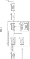
- FIG. 1 is a configuration diagram illustrating a transmission device including a distortion compensation device 2 according to a first embodiment.
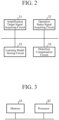
- FIG. 2 is a hardware configuration diagram illustrating hardware of the distortion compensation device 2 according to the first embodiment.
- the transmission device illustrated in FIG. 1 includes a signal generating unit 1, the distortion compensation device 2, a digital-to-analog converter (hereinafter, referred to as "DAC") 3, a power amplifier 4, and a transmission antenna 5.
- DAC digital-to-analog converter
- the signal generating unit 1 generates an amplification target signal which is a signal to be power-amplified by the power amplifier 4.
- the amplification target signal is, for example, a radio frequency (RF) transmission signal.
- the amplification target signal may be an IF baseband signal.
- the signal generating unit 1 outputs the amplification target signal to the distortion compensation device 2.
- the distortion compensation device 2 includes an amplification target signal acquiring unit 21, an operation status signal acquiring unit 22, a learning model storing unit 23, and a distortion compensation unit 25.
- the distortion compensation device 2 acquires the amplification target signal from the signal generating unit 1.
- the distortion compensation device 2 adds distortion capable of compensating distortion generated in the amplification target signal after power amplification by the power amplifier 4 to the amplification target signal.
- the distortion compensation device 2 outputs a predistortion signal, which is an amplification target signal after distortion addition, to the power amplifier 4 via the DAC 3.
- the DAC 3 converts the predistortion signal output from the distortion compensation device 2 from a digital signal to an analog signal.
- the DAC 3 outputs the analog predistortion signal to the power amplifier 4.
- the power amplifier 4 amplifies power of the analog predistortion signal output from the distortion compensation device 2.
- the power amplifier 4 outputs, as a transmission signal, the predistortion signal after power amplification to the transmission antenna 5.
- the transmission antenna 5 emits a radio wave related to the transmission signal output from the power amplifier 4 into space.
- the amplification target signal acquiring unit 21 is implemented by, for example, an amplification target signal acquiring circuit 31 illustrated in FIG. 2 .
- the amplification target signal acquiring unit 21 acquires the amplification target signal from the signal generating unit 1.
- the amplification target signal acquiring unit 21 outputs the amplification target signal to the distortion compensation unit 25.
- the operation status signal acquiring unit 22 is implemented by, for example, an operation status signal acquiring circuit 32 illustrated in FIG. 2 .
- the operation status signal acquiring unit 22 acquires an operation status signal indicating an operation status of the power amplifier 4.
- the operation status signal acquiring unit 22 outputs the operation status signal to the distortion compensation unit 25.
- the operation status signal is a stationary signal having a smaller temporal change in signal value than the amplification target signal.
- the operation status signal is, for example, temperature information indicating an ambient temperature of the power amplifier 4, frequency information indicating a carrier frequency of the amplification target signal acquired by the amplification target signal acquiring unit 21, bias voltage information indicating a bias voltage of the power amplifier 4, or backoff information indicating backoff of the power amplifier 4.
- the learning model storing unit 23 is implemented by, for example, a learning model storing circuit 33 illustrated in FIG. 2 .
- the learning model storing unit 23 stores a learning model 24.
- the distortion compensation device 2 illustrated in FIG. 1 includes the learning model storing unit 23.
- the learning model storing unit 23 may be disposed outside the distortion compensation device 2.
- the learning model 24 is implemented by, for example, a neural network.
- the amplification target signal acquired by the amplification target signal acquiring unit 21 the operation status signal acquired by the operation status signal acquiring unit 22, and the predistortion signal capable of compensating distortion generated in the amplification target signal after power amplification by the power amplifier 4 are given as training data.
- the learning model 24 is a trained model in which the predistortion signal included in the training data has been learned.
- the distortion compensation unit 25 is implemented by, for example, a distortion compensation circuit 35 illustrated in FIG. 2 .
- the distortion compensation unit 25 estimates a signal in which distortion is added to the amplification target signal acquired by the amplification target signal acquiring unit 21 as the predistortion signal for compensating distortion generated in the amplification target signal after power amplification by the power amplifier 4 on the basis of the amplification target signal acquired by the amplification target signal acquiring unit 21 and the operation status signal acquired by the operation status signal acquiring unit 22.
- the distortion compensation unit 25 gives the amplification target signal acquired by the amplification target signal acquiring unit 21 and the operation status signal acquired by the operation status signal acquiring unit 22 to the learning model 24.
- the distortion compensation unit 25 acquires, from the learning model 24, a signal in which distortion is added to the amplification target signal acquired by the amplification target signal acquiring unit 21 as the predistortion signal for compensating distortion generated in the amplification target signal after power amplification by the power amplifier 4.
- the distortion compensation unit 25 outputs the predistortion signal to the power amplifier 4 via the DAC 3.
- the distortion compensation unit 25 estimates the predistortion signal for compensating distortion generated in the amplification target signal after power amplification by the power amplifier 4 using the learning model 24.
- the distortion compensation unit 25 may estimate the predistortion signal for compensating distortion generated in the amplification target signal after power amplification by the power amplifier 4 using, for example, a rule base.
- a rule base a rule for determining predistortion signals corresponding to the amplification target signal acquired by the amplification target signal acquiring unit 21 and the operation status signal acquired by the operation status signal acquiring unit 22 is described.
- each of the amplification target signal acquiring unit 21, the operation status signal acquiring unit 22, the learning model storing unit 23, and the distortion compensation unit 25, which are constituent elements of the distortion compensation device 2 is implemented by dedicated hardware as illustrated in FIG. 2 . That is, it is assumed that the distortion compensation device 2 is implemented by the amplification target signal acquiring circuit 31, the operation status signal acquiring circuit 32, the learning model storing circuit 33, and the distortion compensation circuit 35.
- a nonvolatile or volatile semiconductor memory such as a random access memory (RAM), a read only memory (ROM), a flash memory, an erasable programmable read only memory (EPROM), or an electrically erasable programmable read only memory (EEPROM), a magnetic disk, a flexible disk, an optical disc, a compact disc, a mini disc, or a digital versatile disc (DVD) corresponds.
- RAM random access memory
- ROM read only memory
- EPROM erasable programmable read only memory
- EEPROM electrically erasable programmable read only memory
- a single circuit a composite circuit, a programmed processor, a parallel programmed processor, an application specific integrated circuit (ASIC), a field-programmable gate array (FPGA), or a combination thereof corresponds.
- ASIC application specific integrated circuit
- FPGA field-programmable gate array
- the constituent elements of the distortion compensation device 2 are not limited to those implemented by dedicated hardware, and the distortion compensation device 2 may be implemented by software, firmware, or a combination of software and firmware.
- the computer means hardware for executing a program.
- a central processing unit CPU
- a central processing device for example, a central processing device, a processing device, an arithmetic device, a microprocessor, a microcomputer, a processor, or a digital signal processor (DSP) corresponds.
- DSP digital signal processor
- FIG. 3 is a hardware configuration diagram of a computer in a case where the distortion compensation device 2 is implemented by software, firmware, or the like.
- the learning model storing unit 23 is constituted on a memory 41 of the computer.
- a program for causing the computer to execute a processing procedure performed in each of the amplification target signal acquiring unit 21, the operation status signal acquiring unit 22, and the distortion compensation unit 25 is stored in the memory 41.
- a processor 42 of the computer executes the program stored in the memory 41.
- FIG. 2 illustrates an example in which each of the constituent elements of the distortion compensation device 2 is implemented by dedicated hardware
- FIG. 3 illustrates an example in which the distortion compensation device 2 is implemented by software, firmware, or the like.
- this is merely an example, and some of the constituent elements of the distortion compensation device 2 may be implemented by dedicated hardware, and the remaining constituent elements may be implemented by software, firmware, or the like.
- the signal generating unit 1 generates an amplification target signal S which is a signal to be power-amplified.
- the amplification target signal S includes, for example, an I signal which is an in-phase signal and a Q signal which is a quadrature signal.
- I IN (t) the I signal at time (t) generated by the signal generating unit 1
- Q IN (t) the Q signal at time (t)
- the signal generating unit 1 outputs the amplification target signal S to the distortion compensation device 2.
- the signal generating unit 1 generates the amplification target signal S including the I signal and the Q signal.
- the amplification target signal S may be any signal that can be amplified by the power amplifier 4, and may be a signal not including the I signal and the Q signal.
- FIG. 4 is a flowchart illustrating a distortion compensation method which is a processing procedure performed by the distortion compensation device 2.
- the amplification target signal acquiring unit 21 of the distortion compensation device 2 acquires the amplification target signal S from the signal generating unit 1 (step ST1 in FIG. 4 ).
- the amplification target signal acquiring unit 21 outputs the amplification target signal S to the distortion compensation unit 25.
- the operation status signal acquiring unit 22 acquires an operation status signal OC indicating an operation status of the power amplifier 4 (step ST2 in FIG. 4 ).
- the operation status signal acquiring unit 22 outputs the operation status signal OC to the distortion compensation unit 25.
- the operation status signal acquiring unit 22 acquires the operation status signal OC from a temperature sensor that observes the ambient temperature of the power amplifier 4.
- the operation status signal acquiring unit 22 acquires the operation status signal OC from a control device that controls the transmission device.
- the operation status signal acquiring unit 22 acquires one operation status signal OC and outputs the one operation status signal OC to the distortion compensation unit 25.
- the operation status signal acquiring unit 22 may obtain two or more operation status signals OC and output the two or more operation status signals OC to the distortion compensation unit 25.
- the distortion compensation unit 25 acquires the amplification target signal S from the amplification target signal acquiring unit 21, and acquires the operation status signal OC from the operation status signal acquiring unit 22.
- the amplification target signal S includes I IN (t) and Q IN (t).
- the distortion compensation unit 25 gives each of I IN (t), Q IN (t), and the operation status signal OC to the learning model 24.
- the distortion compensation unit 25 acquires, from the learning model 24, a predistortion signal for compensating distortion generated in an amplification target signal S' after power amplification by the power amplifier 4 (step ST3 in FIG. 4 ).
- the predistortion signal is a signal in which distortion is added to the amplification target signal S in order to eliminate distortion generated in the amplification target signal S' after power amplification by the power amplifier 4.
- the distortion added to the amplification target signal S is distortion having a characteristic opposite to the distortion generated in the amplification target signal S' after power amplification by the power amplifier 4.
- the predistortion signal output from the learning model 24 includes I OUT (t) and Q OUT (t).
- the distortion compensation unit 25 outputs the predistortion signal including I OUT (t) and Q OUT (t) to the power amplifier 4 via the DAC 3 (step ST4 in FIG. 4 ).
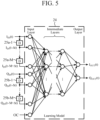
- FIG. 5 is an explanatory diagram illustrating configuration examples of the distortion compensation unit 25 and the learning model 24.
- each of the first delayers 25a-m and the second delayers 25b-m is denoted as "D".
- D a sampling interval of the distortion compensation unit 25
- I IN (t) at time (t) is given to any one of a plurality of input layers of the learning model 24.
- a first delayer 25a-1 delays I IN (t) at time (t) by one sampling time ⁇ t.
- I IN (t- ⁇ t) which is an output signal of the first delayer 25a-1, is obtained by delaying a signal given before one sampling time by ⁇ t, and is given to any one of the plurality of input layers.
- I IN (t- ⁇ t) is given to a first delayer 25a-2.
- I IN (t-m• ⁇ t) which is an output signal of the first delayer 25a-m, is obtained by delaying a signal given before one sampling time by ⁇ t, and is given to any one of the plurality of input layers.
- Q IN (t) at time (t) is given to any one of the plurality of input layers of the learning model 24.
- a second delayer 25b-1 delays Q IN (t) at time (t) by one sampling time ⁇ t.
- Q IN (t- ⁇ t) which is an output signal of the second delayer 25b-1, is obtained by delaying a signal given before one sampling time by ⁇ t, and is given to any one of the plurality of input layers.
- Q IN (t- ⁇ t) is given to a second delayer 25b-2.
- Q IN (t-m• ⁇ t) which is an output signal of the second delayer 25b-m, is obtained by delaying a signal given before one sampling time by ⁇ t, and is given to any one of the plurality of input layers.
- the operation status signal OC is given to an input layer other than an input layer to which I IN (t), I IN (t-m• ⁇ t), Q IN (t), or Q IN (t-m• ⁇ t) is given.
- the operation status signal OC for example, an operation status signal OC indicating temperature information, an operation status signal OC indicating frequency information, an operation status signal OC indicating bias information, or an operation status signal OC indicating backoff information is given to an input layer.
- a signal given to an input layer of the learning model 24 is propagated to each of a plurality of intermediate layers in the learning model 24.
- Weight addition of the plurality of signals propagated to each of the intermediate layers is performed on the basis of a weighting factor determined by learning of the predistortion signal included in the training data.
- the signal subjected to the weight addition in each of the intermediate layers is propagated to each of two output layers.
- Weight addition of the plurality of signals propagated to each of the output layers is performed on the basis of a weighting factor determined by learning of the predistortion signal included in the training data.
- the signal subjected to weight addition in each of the output layers is an amplification target signal after distortion addition.
- the amplification target signal after distortion addition is a predistortion signal including I OUT (t) and Q OUT (t).
- the distortion compensation unit 25 can acquire the predistortion signal corresponding to a temporal change of the amplification target signal S from the learning model 24.
- the input layer of the learning model 24 is not limited to one to which a time-series signal is given, and may be one to which only I IN (t) and Q IN (t) are given.
- the DAC 3 acquires the predistortion signal, which is an amplification target signal after distortion addition, from the distortion compensation device 2.
- the DAC 3 converts the predistortion signal output from a digital signal to an analog signal.
- the DAC 3 outputs the analog predistortion signal to the power amplifier 4.
- the power amplifier 4 acquires the analog predistortion signal from the distortion compensation device 2.
- the power amplifier 4 amplifies power of the analog predistortion signal, and outputs the predistortion signal after power amplification to the transmission antenna 5.
- the predistortion signal is an amplification target signal to which distortion is added in order to compensate distortion generated in a signal after power amplification by the power amplifier 4. Therefore, the transmission signal, which is a signal after power amplification by the power amplifier 4, is a signal in which little distortion is generated.
- the power amplifier 4 outputs the transmission signal after power amplification to the transmission antenna 5.
- the transmission antenna 5 emits a radio wave related to the transmission signal output from the power amplifier 4 into space.
- the distortion compensation device 2 includes the amplification target signal acquiring unit 21 that acquires an amplification target signal which is a signal to be power-amplified by the power amplifier 4 and the operation status signal acquiring unit 22 that acquires an operation status signal indicating an operation status of the power amplifier 4.
- the distortion compensation device 2 includes the distortion compensation unit 25 that estimates a signal in which distortion is added to the amplification target signal acquired by the amplification target signal acquiring unit 21 as a predistortion signal for compensating distortion generated in the amplification target signal after power amplification by the power amplifier 4 on the basis of the amplification target signal acquired by the amplification target signal acquiring unit 21 and the operation status signal acquired by the operation status signal acquiring unit 22, and outputs the predistortion signal to the power amplifier 4. Therefore, even when an operation status of the power amplifier 4 changes, the distortion compensation device 2 can compensate distortion generated in a signal after power amplification by the power amplifier 4.
- a distortion compensation device 2 including a learning processing unit 26 that gives training data to a learning model 24 and causes the learning model 24 to learn a predistortion signal included in the training data will be described.
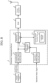
- FIG. 6 is a configuration diagram illustrating a transmission device including the distortion compensation device 2 according to the second embodiment.
- the same reference numerals as in FIG. 1 indicate the same or corresponding parts, and therefore description thereof is omitted.
- FIG. 7 is a hardware configuration diagram illustrating hardware of the distortion compensation device 2 according to the second embodiment.
- the same reference numerals as in FIG. 2 indicate the same or corresponding parts, and therefore description thereof is omitted.
- the transmission device illustrated in FIG. 6 includes a signal generating unit 1, the distortion compensation device 2, a DAC 3, a power amplifier 4, a transmission antenna 5, and an analog-to-digital converter (hereinafter, referred to as "ADC") 6.
- ADC analog-to-digital converter
- the ADC 6 converts an amplification target signal after power amplification by the power amplifier 4 from an analog signal to a digital signal.
- the ADC 6 outputs the digital amplification target signal to the distortion compensation device 2.
- the distortion compensation device 2 illustrated in FIG. 6 includes an amplification target signal acquiring unit 21, an operation status signal acquiring unit 22, a learning model storing unit 23, a distortion compensation unit 25, and a learning processing unit 26.
- the learning processing unit 26 is implemented by, for example, a learning processing circuit 36 illustrated in FIG. 7 .
- the learning processing unit 26 acquires training data to be given to the learning model 24.
- the training data acquired by the learning processing unit 26 includes the digital amplification target signal output from the ADC 6, an operation status signal acquired by the operation status signal acquiring unit 22, and a predistortion signal output from the distortion compensation unit 25.
- the digital amplification target signal output from the ADC 6 corresponds to an amplification target signal after power amplification by the power amplifier 4.
- the predistortion signal included in the training data is a signal used as a teacher signal.
- the learning processing unit 26 gives the training data to the learning model 24 and causes the learning model 24 to learn the predistortion signal included in the training data.
- each of the amplification target signal acquiring unit 21, the operation status signal acquiring unit 22, the learning model storing unit 23, the distortion compensation unit 25, and the learning processing unit 26, which are constituent elements of the distortion compensation device 2 is implemented by dedicated hardware as illustrated in FIG. 7 . That is, it is assumed that the distortion compensation device 2 is implemented by the amplification target signal acquiring circuit 31, the operation status signal acquiring circuit 32, the learning model storing circuit 33, the distortion compensation circuit 35, and the learning processing circuit 36.
- the operation status signal acquiring circuit 32, the distortion compensation circuit 35, and the learning processing circuit 36 for example, a single circuit, a composite circuit, a programmed processor, a parallel programmed processor, an ASIC, a FPGA, or a combination thereof corresponds.
- the constituent elements of the distortion compensation device 2 are not limited to those implemented by dedicated hardware, and the distortion compensation device 2 may be implemented by software, firmware, or a combination of software and firmware.
- the learning model storing unit 23 is constituted on a memory 41 illustrated in FIG. 3 .
- a program for causing a computer to execute a processing procedure performed in each of the amplification target signal acquiring unit 21, the operation status signal acquiring unit 22, the distortion compensation unit 25, and the learning processing unit 26 is stored in the memory 41.
- a processor 42 illustrated in FIG. 3 executes the program stored in the memory 41.
- FIG. 7 illustrates an example in which each of the constituent elements of the distortion compensation device 2 is implemented by dedicated hardware
- FIG. 3 illustrates an example in which the distortion compensation device 2 is implemented by software, firmware, or the like.
- this is merely an example, and some of the constituent elements of the distortion compensation device 2 may be implemented by dedicated hardware, and the remaining constituent elements may be implemented by software, firmware, or the like.
- FIG. 9 is a hardware configuration diagram illustrating hardware of the distortion compensation device 2 according to the third embodiment.
- the same reference numerals as in FIGS. 2 and 7 indicate the same or corresponding parts, and therefore description thereof is omitted.
- the learning model storing unit 23 is constituted on a memory 41 illustrated in FIG. 3 .
- a program for causing a computer to execute a processing procedure performed in each of the amplification target signal acquiring unit 21, the operation status signal acquiring unit 22, the signal value adjusting unit 27, and the distortion compensation unit 25 is stored in the memory 41.
- a processor 42 illustrated in FIG. 3 executes the program stored in the memory 41.
- the signal value adjusting unit 27 acquires the amplification target signal S from the amplification target signal acquiring unit 21, and acquires the operation status signal OC from the operation status signal acquiring unit 22.
- the signal value adjusting unit 27 adjusts a signal value of the operation status signal OC in such a manner that a signal change width of the operation status signal OC is equal to a signal change width of the amplification target signal S.
- the signal value adjusting unit 27 adjusts the signal value of the operation status signal OC to "1" in such a manner that the signal value is equal to the upper limit value "1" of the signal value of the amplification target signal S.
- the signal value adjusting unit 27 adjusts the signal value of the operation status signal OC to "0" in such a manner that the signal value is equal to the median value "0" of the signal value of the amplification target signal S.
- the signal value adjusting unit 27 outputs the operation status signal OC' after signal value adjustment to the distortion compensation unit 25.
- the operation status signal OC is frequency information indicating a carrier frequency of the amplification target signal.
- the operation status signal OC may be temperature information indicating an ambient temperature of the power amplifier 4, bias voltage information indicating a bias voltage of the power amplifier 4, or backoff information indicating backoff of the power amplifier 4.
- the signal value adjusting unit 27 adjusts the signal value of the operation status signal OC similarly to the frequency information indicating a carrier frequency.
- the distortion compensation unit 25 acquires the amplification target signal S from the amplification target signal acquiring unit 21, and acquires the operation status signal OC' after signal value adjustment from the signal value adjusting unit 27.
- the amplification target signal includes I IN (t) and Q IN (t).
- the distortion compensation unit 25 gives each of I IN (t), Q IN (t), and the operation status signal OC' to the trained learning model 24.
- an upper limit of a weight for the amplification target signal S in a neural network is the same as an upper limit of a weight for the operation status signal OC' in the neural network by the operation status signal OC' after signal value adjustment being given to the learning model 24. Therefore, biased learning in which the amplification target signal S is emphasized more than the operation status signal OC is prevented. In addition, biased learning in which the operation status signal OC is emphasized more than the amplification target signal S is prevented. That is, the amplification target signal S and the operation status signal OC' are learned with a similar weight. As a result, predistortion signal learning accuracy by the learning model 24 is improved.
- the distortion compensation unit 25 can acquire a predistortion signal with high distortion compensation accuracy.
- the distortion compensation device 2 illustrated in FIG. 8 includes the signal value adjusting unit 27 that adjusts a signal value of an operation status signal acquired by the operation status signal acquiring unit 22 in such a manner that a signal change width of the operation status signal is equal to a signal change width of an amplification target signal acquired by the amplification target signal acquiring unit 21, and outputs the operation status signal after signal value adjustment to the distortion compensation unit 25. Therefore, even when an operation status of the power amplifier 4 changes, the distortion compensation device 2 illustrated in FIG. 8 can compensate distortion generated in a signal after power amplification by the power amplifier 4, and can compensate distortion with higher accuracy than the distortion compensation device 2 illustrated in FIG. 1 .
- Each of the transmission device illustrated in FIG. 1 and the transmission device illustrated in FIG. 8 includes the signal generating unit 1, the distortion compensation device 2, the DAC 3, the power amplifier 4, and the transmission antenna 5.
- the transmission device illustrated in FIG. 6 includes the signal generating unit 1, the distortion compensation device 2, the DAC 3, the power amplifier 4, the transmission antenna 5, and the ADC 6.
- FIG. 11 is a configuration diagram illustrating an example of a transmission device including the distortion compensation device 2.
- the signal generating unit 1 generates an IF baseband signal as an amplification target signal.
- the quadrature modulator 51 performs quadrature modulation on a baseband signal after distortion addition, which is a predistortion signal output from the distortion compensation device 2, using a carrier signal.
- the quadrature modulator 51 outputs a transmission signal, which is a baseband signal after quadrature modulation, to the DAC 3.
- the frequency converter 52 converts a frequency of the analog transmission signal output from the DAC 3 to, for example, RF.
- the frequency converter 52 outputs the transmission signal having a frequency of RF to the power amplifier 4.
- the directional coupler 53 divides the transmission signal after power amplification by the power amplifier 4 into two.
- the directional coupler 53 outputs one of the two transmission signals after division to the transmission antenna 5 and outputs the other transmission signal to the frequency converter 54.
- the frequency converter 54 converts a frequency of the transmission signal output from the directional coupler 53 to, for example, IF.
- the frequency converter 54 outputs the transmission signal having a frequency of IF to the automatic gain controller 55.
- the automatic gain controller 55 controls a gain of the transmission signal output from the frequency converter 54.
- the automatic gain controller 55 outputs the transmission signal after gain control to the ADC 6.
- the quadrature demodulator 56 performs quadrature demodulation on the digital transmission signal output from the ADC 6 using a carrier signal.
- the quadrature demodulator 56 outputs a baseband signal, which is the transmission signal after quadrature demodulation, to the distortion compensation device 2.
- the present disclosure is suitable for a distortion compensation device, a distortion compensation method, and a transmission device.
Landscapes
- Engineering & Computer Science (AREA)
- Power Engineering (AREA)
- Physics & Mathematics (AREA)
- Nonlinear Science (AREA)
- Algebra (AREA)
- General Physics & Mathematics (AREA)
- Mathematical Analysis (AREA)
- Mathematical Optimization (AREA)
- Pure & Applied Mathematics (AREA)
- Signal Processing (AREA)
- Computer Networks & Wireless Communication (AREA)
- Amplifiers (AREA)
- Transmitters (AREA)
Abstract
Description
- The present disclosure relates to a distortion compensation device, a distortion compensation method, and a transmission device.
- There is a transmission device including a power amplifier that amplifies power of a transmission signal. A non-linear characteristic of the power amplifier may generate distortion in an amplification target signal after power amplification by the power amplifier. For example, Non-Patent
Literature 1 discloses a distortion compensation device for compensating distortion generated in a transmission signal after power amplification by a power amplifier. The distortion compensation device includes a distortion compensation unit that gives a transmission signal to be power-amplified to a neural network (hereinafter, referred to as a "learning model") and acquires, from the learning model, a predistortion signal for compensating distortion generated in the transmission signal after power amplification by the power amplifier. The distortion compensation unit outputs the predistortion signal to the power amplifier as the transmission signal. - Non-Patent Literature 1: Slim Boumaiza, and Farouk Mkadem, "Wideband RF Power Amplifier Predistortion using Real-Valued Time-Delay Neural Networks", European Microwave Conference (EuMC), 2009.
- By change of an operation status of a power amplifier, distortion generated in a transmission signal after power amplification by the power amplifier changes. Examples of the operation status of the power amplifier include an ambient temperature of the power amplifier, a carrier frequency of the transmission signal, and a bias voltage of the power amplifier.
- In the distortion compensation device disclosed in
Non-Patent Literature 1, an operation status of the power amplifier at the time of training of the learning model may be different from an operation status of the power amplifier when the distortion compensation unit acquires the predistortion signal from the learning model. As described above, when there is a difference in the operation status of the power amplifier, there is a difference in the distortion generated in the transmission signal after power amplification by the power amplifier. For this reason, even when the distortion compensation unit outputs, as the transmission signal, the predistortion signal acquired from the learning model to the power amplifier, there is a problem that the distortion generated in the transmission signal after power amplification by the power amplifier may not be compensated. - The present disclosure has been made in order to solve the problem as described above, and an object of the present disclosure is to obtain a distortion compensation device capable of compensating distortion generated in a signal after power amplification by a power amplifier even when an operation status of the power amplifier changes.
- The distortion compensation device according to the present disclosure includes: an amplification target signal acquiring unit to acquire an amplification target signal which is a signal to which power amplification by a power amplifier is performed; an operation status signal acquiring unit to acquire an operation status signal indicating an operation status of the power amplifier; and a distortion compensation unit to estimate a signal in which distortion is added to the amplification target signal acquired by the amplification target signal acquiring unit as a predistortion signal for performing compensation of distortion generated in the amplification target signal after the power amplification by the power amplifier on a basis of the amplification target signal acquired by the amplification target signal acquiring unit and the operation status signal acquired by the operation status signal acquiring unit, and to output the predistortion signal to the power amplifier.
- According to the present disclosure, even when an operation status of the power amplifier changes, distortion generated in a signal after power amplification by the power amplifier can be compensated.
-
-
FIG. 1 is a configuration diagram illustrating a transmission device including adistortion compensation device 2 according to a first embodiment. -
FIG. 2 is a hardware configuration diagram illustrating hardware of thedistortion compensation device 2 according to the first embodiment. -
FIG. 3 is a hardware configuration diagram of a computer in a case where thedistortion compensation device 2 is implemented by software, firmware, or the like. -
FIG. 4 is a flowchart illustrating a distortion compensation method which is a processing procedure performed by thedistortion compensation device 2. -
FIG. 5 is an explanatory diagram illustrating configuration examples of adistortion compensation unit 25 and alearning model 24. -
FIG. 6 is a configuration diagram illustrating a transmission device including adistortion compensation device 2 according to a second embodiment. -
FIG. 7 is a hardware configuration diagram illustrating hardware of thedistortion compensation device 2 according to the second embodiment. -
FIG. 8 is a configuration diagram illustrating a transmission device including adistortion compensation device 2 according to a third embodiment. -
FIG. 9 is a hardware configuration diagram illustrating hardware of thedistortion compensation device 2 according to the third embodiment. -
FIG. 10 is an explanatory diagram illustrating details of signal value adjustment performed by a signalvalue adjusting unit 27. -
FIG. 11 is a configuration diagram illustrating an example of a transmission device including thedistortion compensation device 2. - Hereinafter, in order to describe the present disclosure in more detail, embodiments for carrying out the present disclosure will be described with reference to the attached drawings.
-
FIG. 1 is a configuration diagram illustrating a transmission device including adistortion compensation device 2 according to a first embodiment. -
FIG. 2 is a hardware configuration diagram illustrating hardware of thedistortion compensation device 2 according to the first embodiment. - The transmission device illustrated in
FIG. 1 includes asignal generating unit 1, thedistortion compensation device 2, a digital-to-analog converter (hereinafter, referred to as "DAC") 3, apower amplifier 4, and a transmission antenna 5. - The signal generating
unit 1 generates an amplification target signal which is a signal to be power-amplified by thepower amplifier 4. The amplification target signal is, for example, a radio frequency (RF) transmission signal. - When a frequency converter that converts an intermediate frequency (IF) baseband signal to an RF transmission signal is disposed at a preceding stage of the
power amplifier 4, the amplification target signal may be an IF baseband signal. - The signal generating
unit 1 outputs the amplification target signal to thedistortion compensation device 2. - The
distortion compensation device 2 includes an amplification targetsignal acquiring unit 21, an operation statussignal acquiring unit 22, a learningmodel storing unit 23, and adistortion compensation unit 25. - The
distortion compensation device 2 acquires the amplification target signal from thesignal generating unit 1. - The
distortion compensation device 2 adds distortion capable of compensating distortion generated in the amplification target signal after power amplification by thepower amplifier 4 to the amplification target signal. - The
distortion compensation device 2 outputs a predistortion signal, which is an amplification target signal after distortion addition, to thepower amplifier 4 via the DAC 3. - The DAC 3 converts the predistortion signal output from the
distortion compensation device 2 from a digital signal to an analog signal. - The DAC 3 outputs the analog predistortion signal to the
power amplifier 4. - The
power amplifier 4 amplifies power of the analog predistortion signal output from thedistortion compensation device 2. - The power amplifier 4 outputs, as a transmission signal, the predistortion signal after power amplification to the transmission antenna 5.
- The transmission antenna 5 emits a radio wave related to the transmission signal output from the
power amplifier 4 into space. - The amplification target
signal acquiring unit 21 is implemented by, for example, an amplification targetsignal acquiring circuit 31 illustrated inFIG. 2 . - The amplification target
signal acquiring unit 21 acquires the amplification target signal from thesignal generating unit 1. - The amplification target
signal acquiring unit 21 outputs the amplification target signal to thedistortion compensation unit 25. - The operation status
signal acquiring unit 22 is implemented by, for example, an operation statussignal acquiring circuit 32 illustrated inFIG. 2 . - The operation status
signal acquiring unit 22 acquires an operation status signal indicating an operation status of thepower amplifier 4. - The operation status
signal acquiring unit 22 outputs the operation status signal to thedistortion compensation unit 25. The operation status signal is a stationary signal having a smaller temporal change in signal value than the amplification target signal. - The operation status signal is, for example, temperature information indicating an ambient temperature of the
power amplifier 4, frequency information indicating a carrier frequency of the amplification target signal acquired by the amplification targetsignal acquiring unit 21, bias voltage information indicating a bias voltage of thepower amplifier 4, or backoff information indicating backoff of thepower amplifier 4. - When the ambient temperature of the
power amplifier 4 changes, distortion generated in the amplification target signal after power amplification by thepower amplifier 4 changes. When the carrier frequency of the amplification target signal changes, the distortion generated in the amplification target signal after power amplification by thepower amplifier 4 changes. When the bias voltage of thepower amplifier 4 changes, the distortion generated in the amplification target signal after power amplification by thepower amplifier 4 changes. When the backoff of thepower amplifier 4 changes, the distortion generated in the amplification target signal after power amplification by thepower amplifier 4 changes. - The learning
model storing unit 23 is implemented by, for example, a learningmodel storing circuit 33 illustrated inFIG. 2 . - The learning
model storing unit 23 stores alearning model 24. - The
distortion compensation device 2 illustrated inFIG. 1 includes the learningmodel storing unit 23. However, this is merely an example, and the learningmodel storing unit 23 may be disposed outside thedistortion compensation device 2. - The
learning model 24 is implemented by, for example, a neural network. - To the
learning model 24, at the time of training, the amplification target signal acquired by the amplification targetsignal acquiring unit 21, the operation status signal acquired by the operation statussignal acquiring unit 22, and the predistortion signal capable of compensating distortion generated in the amplification target signal after power amplification by thepower amplifier 4 are given as training data. - The
learning model 24 is a trained model in which the predistortion signal included in the training data has been learned. - The
distortion compensation unit 25 is implemented by, for example, adistortion compensation circuit 35 illustrated inFIG. 2 . - The
distortion compensation unit 25 estimates a signal in which distortion is added to the amplification target signal acquired by the amplification targetsignal acquiring unit 21 as the predistortion signal for compensating distortion generated in the amplification target signal after power amplification by thepower amplifier 4 on the basis of the amplification target signal acquired by the amplification targetsignal acquiring unit 21 and the operation status signal acquired by the operation statussignal acquiring unit 22. - Specifically, the
distortion compensation unit 25 gives the amplification target signal acquired by the amplification targetsignal acquiring unit 21 and the operation status signal acquired by the operation statussignal acquiring unit 22 to thelearning model 24. - The
distortion compensation unit 25 acquires, from thelearning model 24, a signal in which distortion is added to the amplification target signal acquired by the amplification targetsignal acquiring unit 21 as the predistortion signal for compensating distortion generated in the amplification target signal after power amplification by thepower amplifier 4. - The
distortion compensation unit 25 outputs the predistortion signal to thepower amplifier 4 via the DAC 3. - In the
distortion compensation device 2 illustrated inFIG. 1 , thedistortion compensation unit 25 estimates the predistortion signal for compensating distortion generated in the amplification target signal after power amplification by thepower amplifier 4 using thelearning model 24. However, this is merely an example, and thedistortion compensation unit 25 may estimate the predistortion signal for compensating distortion generated in the amplification target signal after power amplification by thepower amplifier 4 using, for example, a rule base. In the rule base, a rule for determining predistortion signals corresponding to the amplification target signal acquired by the amplification targetsignal acquiring unit 21 and the operation status signal acquired by the operation statussignal acquiring unit 22 is described. - In
FIG. 1 , it is assumed that each of the amplification targetsignal acquiring unit 21, the operation statussignal acquiring unit 22, the learningmodel storing unit 23, and thedistortion compensation unit 25, which are constituent elements of thedistortion compensation device 2, is implemented by dedicated hardware as illustrated inFIG. 2 . That is, it is assumed that thedistortion compensation device 2 is implemented by the amplification targetsignal acquiring circuit 31, the operation statussignal acquiring circuit 32, the learningmodel storing circuit 33, and thedistortion compensation circuit 35. - To the learning
model storing circuit 33, a nonvolatile or volatile semiconductor memory such as a random access memory (RAM), a read only memory (ROM), a flash memory, an erasable programmable read only memory (EPROM), or an electrically erasable programmable read only memory (EEPROM), a magnetic disk, a flexible disk, an optical disc, a compact disc, a mini disc, or a digital versatile disc (DVD) corresponds. - To each of the amplification target
signal acquiring circuit 31, the operation statussignal acquiring circuit 32, and thedistortion compensation circuit 35, a single circuit, a composite circuit, a programmed processor, a parallel programmed processor, an application specific integrated circuit (ASIC), a field-programmable gate array (FPGA), or a combination thereof corresponds. - The constituent elements of the
distortion compensation device 2 are not limited to those implemented by dedicated hardware, and thedistortion compensation device 2 may be implemented by software, firmware, or a combination of software and firmware. - Software or firmware is stored as a program in a memory of a computer. The computer means hardware for executing a program. To the computer, for example, a central processing unit (CPU), a central processing device, a processing device, an arithmetic device, a microprocessor, a microcomputer, a processor, or a digital signal processor (DSP) corresponds.
-
FIG. 3 is a hardware configuration diagram of a computer in a case where thedistortion compensation device 2 is implemented by software, firmware, or the like. - In a case where the
distortion compensation device 2 is implemented by software, firmware, or the like, the learningmodel storing unit 23 is constituted on amemory 41 of the computer. A program for causing the computer to execute a processing procedure performed in each of the amplification targetsignal acquiring unit 21, the operation statussignal acquiring unit 22, and thedistortion compensation unit 25 is stored in thememory 41. Aprocessor 42 of the computer executes the program stored in thememory 41. -
FIG. 2 illustrates an example in which each of the constituent elements of thedistortion compensation device 2 is implemented by dedicated hardware, andFIG. 3 illustrates an example in which thedistortion compensation device 2 is implemented by software, firmware, or the like. However, this is merely an example, and some of the constituent elements of thedistortion compensation device 2 may be implemented by dedicated hardware, and the remaining constituent elements may be implemented by software, firmware, or the like. - Next, an operation of the
distortion compensation device 2 illustrated inFIG. 1 will be described. - The
signal generating unit 1 generates an amplification target signal S which is a signal to be power-amplified. The amplification target signal S includes, for example, an I signal which is an in-phase signal and a Q signal which is a quadrature signal. - Hereinafter, the I signal at time (t) generated by the
signal generating unit 1 is represented by IIN(t), and the Q signal at time (t) is represented by QIN(t). - The
signal generating unit 1 outputs the amplification target signal S to thedistortion compensation device 2. - In the
distortion compensation device 2 illustrated inFIG. 1 , thesignal generating unit 1 generates the amplification target signal S including the I signal and the Q signal. However, the amplification target signal S may be any signal that can be amplified by thepower amplifier 4, and may be a signal not including the I signal and the Q signal. -
FIG. 4 is a flowchart illustrating a distortion compensation method which is a processing procedure performed by thedistortion compensation device 2. - The amplification target
signal acquiring unit 21 of thedistortion compensation device 2 acquires the amplification target signal S from the signal generating unit 1 (step ST1 inFIG. 4 ). - The amplification target
signal acquiring unit 21 outputs the amplification target signal S to thedistortion compensation unit 25. - The operation status
signal acquiring unit 22 acquires an operation status signal OC indicating an operation status of the power amplifier 4 (step ST2 inFIG. 4 ). - The operation status
signal acquiring unit 22 outputs the operation status signal OC to thedistortion compensation unit 25. - When the operation status signal OC is, for example, temperature information indicating an ambient temperature of the
power amplifier 4, the operation statussignal acquiring unit 22 acquires the operation status signal OC from a temperature sensor that observes the ambient temperature of thepower amplifier 4. - When the operation status signal OC is, for example, frequency information indicating a carrier frequency of the amplification target signal, the operation status
signal acquiring unit 22 acquires the operation status signal OC from a control device that controls the transmission device. - In the
distortion compensation device 2 illustrated inFIG. 1 , the operation statussignal acquiring unit 22 acquires one operation status signal OC and outputs the one operation status signal OC to thedistortion compensation unit 25. However, this is merely an example, and the operation statussignal acquiring unit 22 may obtain two or more operation status signals OC and output the two or more operation status signals OC to thedistortion compensation unit 25. - The
distortion compensation unit 25 acquires the amplification target signal S from the amplification targetsignal acquiring unit 21, and acquires the operation status signal OC from the operation statussignal acquiring unit 22. In thedistortion compensation device 2 illustrated inFIG. 1 , the amplification target signal S includes IIN(t) and QIN(t). - The
distortion compensation unit 25 gives each of IIN(t), QIN(t), and the operation status signal OC to thelearning model 24. - The
distortion compensation unit 25 acquires, from thelearning model 24, a predistortion signal for compensating distortion generated in an amplification target signal S' after power amplification by the power amplifier 4 (step ST3 inFIG. 4 ). - The predistortion signal is a signal in which distortion is added to the amplification target signal S in order to eliminate distortion generated in the amplification target signal S' after power amplification by the
power amplifier 4. Generally, the distortion added to the amplification target signal S is distortion having a characteristic opposite to the distortion generated in the amplification target signal S' after power amplification by thepower amplifier 4. - The predistortion signal output from the
learning model 24 includes IOUT(t) and QOUT(t). - The
distortion compensation unit 25 outputs the predistortion signal including IOUT(t) and QOUT(t) to thepower amplifier 4 via the DAC 3 (step ST4 inFIG. 4 ). -
FIG. 5 is an explanatory diagram illustrating configuration examples of thedistortion compensation unit 25 and thelearning model 24. - In
FIG. 5 , thedistortion compensation unit 25 includes Mfirst delayers 25a-m and Msecond delayers 25b-m. m = 1, ···, M, and M is an integer equal to or more than 2. InFIG. 5 , each of thefirst delayers 25a-m and thesecond delayers 25b-m is denoted as "D". Here, it is assumed that a sampling interval of thedistortion compensation unit 25 is Δt. - IIN(t) at time (t) is given to any one of a plurality of input layers of the
learning model 24. Afirst delayer 25a-1 delays IIN(t) at time (t) by one sampling time Δt. - IIN(t-Δt), which is an output signal of the
first delayer 25a-1, is obtained by delaying a signal given before one sampling time by Δt, and is given to any one of the plurality of input layers. In addition, IIN(t-Δt) is given to afirst delayer 25a-2. - A
first delayer 25a-m (m=2, ···, M) delays IIN(t-(m-1)•Δt), which is an output signal of afirst delayer 25a-(m-1), by one sampling time Δt. - IIN(t-m•Δt), which is an output signal of the
first delayer 25a-m, is obtained by delaying a signal given before one sampling time by Δt, and is given to any one of the plurality of input layers. In addition, IIN(t-m•Δt) is given to afirst delayer 25a-(m+1). Note that, when m = M, IIN(t-m•Δt) is not given to thefirst delayer 25a-(m+1). - QIN(t) at time (t) is given to any one of the plurality of input layers of the
learning model 24. Asecond delayer 25b-1 delays QIN(t) at time (t) by one sampling time Δt. - QIN(t-Δt), which is an output signal of the
second delayer 25b-1, is obtained by delaying a signal given before one sampling time by Δt, and is given to any one of the plurality of input layers. In addition, QIN(t-Δt) is given to asecond delayer 25b-2. - A
second delayer 25b-m (m=2, ···, M) delays QIN(t-(m-1)•Δt), which is an output signal of asecond delayer 25b-(m-1), by one sampling time Δt. - QIN(t-m•Δt), which is an output signal of the
second delayer 25b-m, is obtained by delaying a signal given before one sampling time by Δt, and is given to any one of the plurality of input layers. In addition, QIN(t-m•Δt) is given to asecond delayer 25b-(m+1). Note that, when m = M, QIN(t-m•Δt) is not given to thesecond delayer 25b-(m+1). - Among the plurality of input layers of the
learning model 24, the operation status signal OC is given to an input layer other than an input layer to which IIN(t), IIN(t-m•Δt), QIN(t), or QIN(t-m•Δt) is given. As the operation status signal OC, for example, an operation status signal OC indicating temperature information, an operation status signal OC indicating frequency information, an operation status signal OC indicating bias information, or an operation status signal OC indicating backoff information is given to an input layer. - A signal given to an input layer of the
learning model 24 is propagated to each of a plurality of intermediate layers in thelearning model 24. Weight addition of the plurality of signals propagated to each of the intermediate layers is performed on the basis of a weighting factor determined by learning of the predistortion signal included in the training data. - The signal subjected to the weight addition in each of the intermediate layers is propagated to each of two output layers. Weight addition of the plurality of signals propagated to each of the output layers is performed on the basis of a weighting factor determined by learning of the predistortion signal included in the training data.
- The signal subjected to weight addition in each of the output layers is an amplification target signal after distortion addition. The amplification target signal after distortion addition is a predistortion signal including IOUT(t) and QOUT(t).
- To an input layer of the
learning model 24 illustrated inFIG. 5 , not only IIN(t) and QIN(t) at a current time t but also IIN(t-m•Δt) and QIN(t-m•Δt) (m = 1, ···, M) are given. Therefore, learning of the predistortion signal is performed in consideration of a change in a time-series signal including a current signal and a past signal. Therefore, thedistortion compensation unit 25 can acquire the predistortion signal corresponding to a temporal change of the amplification target signal S from thelearning model 24. - Note that the input layer of the
learning model 24 is not limited to one to which a time-series signal is given, and may be one to which only IIN(t) and QIN(t) are given. - The DAC 3 acquires the predistortion signal, which is an amplification target signal after distortion addition, from the
distortion compensation device 2. - The DAC 3 converts the predistortion signal output from a digital signal to an analog signal.
- The DAC 3 outputs the analog predistortion signal to the
power amplifier 4. - The
power amplifier 4 acquires the analog predistortion signal from thedistortion compensation device 2. - The
power amplifier 4 amplifies power of the analog predistortion signal, and outputs the predistortion signal after power amplification to the transmission antenna 5. - The predistortion signal is an amplification target signal to which distortion is added in order to compensate distortion generated in a signal after power amplification by the
power amplifier 4. Therefore, the transmission signal, which is a signal after power amplification by thepower amplifier 4, is a signal in which little distortion is generated. - The
power amplifier 4 outputs the transmission signal after power amplification to the transmission antenna 5. - The transmission antenna 5 emits a radio wave related to the transmission signal output from the
power amplifier 4 into space. - In the first embodiment described above, the
distortion compensation device 2 includes the amplification targetsignal acquiring unit 21 that acquires an amplification target signal which is a signal to be power-amplified by thepower amplifier 4 and the operation statussignal acquiring unit 22 that acquires an operation status signal indicating an operation status of thepower amplifier 4. In addition, thedistortion compensation device 2 includes thedistortion compensation unit 25 that estimates a signal in which distortion is added to the amplification target signal acquired by the amplification targetsignal acquiring unit 21 as a predistortion signal for compensating distortion generated in the amplification target signal after power amplification by thepower amplifier 4 on the basis of the amplification target signal acquired by the amplification targetsignal acquiring unit 21 and the operation status signal acquired by the operation statussignal acquiring unit 22, and outputs the predistortion signal to thepower amplifier 4. Therefore, even when an operation status of thepower amplifier 4 changes, thedistortion compensation device 2 can compensate distortion generated in a signal after power amplification by thepower amplifier 4. - In a second embodiment, a
distortion compensation device 2 including alearning processing unit 26 that gives training data to alearning model 24 and causes thelearning model 24 to learn a predistortion signal included in the training data will be described. -
FIG. 6 is a configuration diagram illustrating a transmission device including thedistortion compensation device 2 according to the second embodiment. InFIG. 6 , the same reference numerals as inFIG. 1 indicate the same or corresponding parts, and therefore description thereof is omitted. -
FIG. 7 is a hardware configuration diagram illustrating hardware of thedistortion compensation device 2 according to the second embodiment. InFIG. 7 , the same reference numerals as inFIG. 2 indicate the same or corresponding parts, and therefore description thereof is omitted. - The transmission device illustrated in
FIG. 6 includes asignal generating unit 1, thedistortion compensation device 2, a DAC 3, apower amplifier 4, a transmission antenna 5, and an analog-to-digital converter (hereinafter, referred to as "ADC") 6. - The ADC 6 converts an amplification target signal after power amplification by the
power amplifier 4 from an analog signal to a digital signal. - The ADC 6 outputs the digital amplification target signal to the
distortion compensation device 2. - The
distortion compensation device 2 illustrated inFIG. 6 includes an amplification targetsignal acquiring unit 21, an operation statussignal acquiring unit 22, a learningmodel storing unit 23, adistortion compensation unit 25, and alearning processing unit 26. - The
learning processing unit 26 is implemented by, for example, alearning processing circuit 36 illustrated inFIG. 7 . - The
learning processing unit 26 acquires training data to be given to thelearning model 24. - The training data acquired by the
learning processing unit 26 includes the digital amplification target signal output from the ADC 6, an operation status signal acquired by the operation statussignal acquiring unit 22, and a predistortion signal output from thedistortion compensation unit 25. The digital amplification target signal output from the ADC 6 corresponds to an amplification target signal after power amplification by thepower amplifier 4. The predistortion signal included in the training data is a signal used as a teacher signal. - The
learning processing unit 26 gives the training data to thelearning model 24 and causes thelearning model 24 to learn the predistortion signal included in the training data. - In
FIG. 6 , it is assumed that each of the amplification targetsignal acquiring unit 21, the operation statussignal acquiring unit 22, the learningmodel storing unit 23, thedistortion compensation unit 25, and thelearning processing unit 26, which are constituent elements of thedistortion compensation device 2, is implemented by dedicated hardware as illustrated inFIG. 7 . That is, it is assumed that thedistortion compensation device 2 is implemented by the amplification targetsignal acquiring circuit 31, the operation statussignal acquiring circuit 32, the learningmodel storing circuit 33, thedistortion compensation circuit 35, and thelearning processing circuit 36. - To each of the amplification target
signal acquiring circuit 31, the operation statussignal acquiring circuit 32, thedistortion compensation circuit 35, and thelearning processing circuit 36, for example, a single circuit, a composite circuit, a programmed processor, a parallel programmed processor, an ASIC, a FPGA, or a combination thereof corresponds. - The constituent elements of the
distortion compensation device 2 are not limited to those implemented by dedicated hardware, and thedistortion compensation device 2 may be implemented by software, firmware, or a combination of software and firmware. - In a case where the
distortion compensation device 2 is implemented by software, firmware, or the like, the learningmodel storing unit 23 is constituted on amemory 41 illustrated inFIG. 3 . A program for causing a computer to execute a processing procedure performed in each of the amplification targetsignal acquiring unit 21, the operation statussignal acquiring unit 22, thedistortion compensation unit 25, and thelearning processing unit 26 is stored in thememory 41. Aprocessor 42 illustrated inFIG. 3 executes the program stored in thememory 41. -
FIG. 7 illustrates an example in which each of the constituent elements of thedistortion compensation device 2 is implemented by dedicated hardware, andFIG. 3 illustrates an example in which thedistortion compensation device 2 is implemented by software, firmware, or the like. However, this is merely an example, and some of the constituent elements of thedistortion compensation device 2 may be implemented by dedicated hardware, and the remaining constituent elements may be implemented by software, firmware, or the like. - Next, an operation of the
distortion compensation device 2 illustrated inFIG. 6 will be described. Components other than thelearning processing unit 26 are similar to those of thedistortion compensation device 2 illustrated inFIG. 1 , and therefore an operation of thelearning processing unit 26 will be mainly described here. - Most of power of the amplification target signal after power amplification by the
power amplifier 4 is output to the transmission antenna 5, and a part of the power of the amplification target signal is output to the ADC 6. - The ADC 6 converts an amplification target signal after power amplification by the
power amplifier 4 from an analog signal to a digital signal. - The ADC 6 outputs the digital amplification target signal to the
distortion compensation device 2. - The
learning processing unit 26 acquires training data to be given to thelearning model 24. - That is, the
learning processing unit 26 acquires, as the training data, the digital amplification target signal output from the ADC 6, the operation status signal OC output from the operation statussignal acquiring unit 22, and the predistortion signal output from thedistortion compensation unit 25. - The
learning processing unit 26 gives the training data to thelearning model 24 and causes thelearning model 24 to learn the predistortion signal included in the training data. - When the amplification target signal S acquired by the amplification target
signal acquiring unit 21 and the operation status signal OC acquired by the operation statussignal acquiring unit 22 are given to the trainedlearning model 24, the trainedlearning model 24 outputs a predistortion signal corresponding to each of the amplification target signal S and the operation status signal OC. - The
distortion compensation unit 25 acquires the amplification target signal S from the amplification targetsignal acquiring unit 21, and acquires the operation status signal OC from the operation statussignal acquiring unit 22. The amplification target signal S includes IIN(t) and QIN(t). - The
distortion compensation unit 25 gives each of IIN(t), QIN(t), and the operation status signal OC to the trainedlearning model 24. - The
distortion compensation unit 25 acquires, from thelearning model 24, a predistortion signal for compensating distortion generated in an amplification target signal S' after power amplification by thepower amplifier 4. - In the second embodiment described above, the
distortion compensation device 2 includes thelearning processing unit 26 that acquires, as training data, an amplification target signal after power amplification by thepower amplifier 4, an operation status signal acquired by the operation statussignal acquiring unit 22, and a predistortion signal output from thedistortion compensation unit 25, gives the training data to thelearning model 24, and causes thelearning model 24 to learn the predistortion signal. Therefore, even when an operation status of thepower amplifier 4 changes, thedistortion compensation device 2 can compensate distortion generated in a signal after power amplification by thepower amplifier 4, and can cause thelearning model 24 to learn the predistortion signal. - In a third embodiment, a
distortion compensation device 2 including a signalvalue adjusting unit 27 that adjusts a signal value of an operation status signal OC will be described. -
FIG. 8 is a configuration diagram illustrating a transmission device including thedistortion compensation device 2 according to the third embodiment. InFIG. 8 , the same reference numerals as inFIGS. 1 and6 indicate the same or corresponding parts, and therefore description thereof is omitted. -
FIG. 9 is a hardware configuration diagram illustrating hardware of thedistortion compensation device 2 according to the third embodiment. InFIG. 9 , the same reference numerals as inFIGS. 2 and7 indicate the same or corresponding parts, and therefore description thereof is omitted. - The signal
value adjusting unit 27 is implemented by, for example, a signalvalue adjusting circuit 37 illustrated inFIG. 9 . - The signal
value adjusting unit 27 adjusts a signal value of an operation status signal OC acquired by an operation statussignal acquiring unit 22 in such a manner that a signal change width of the operation status signal OC is equal to a signal change width of an amplification target signal S acquired by an amplification targetsignal acquiring unit 21. - The signal
value adjusting unit 27 outputs an operation status signal OC' after signal value adjustment to adistortion compensation unit 25. - In the
distortion compensation device 2 illustrated inFIG. 8 , the signalvalue adjusting unit 27 is applied to thedistortion compensation device 2 illustrated inFIG. 1 . However, this is merely an example, and the signalvalue adjusting unit 27 may be applied to thedistortion compensation device 2 illustrated inFIG. 6 . - In
FIG. 8 , it is assumed that each of the amplification targetsignal acquiring unit 21, the operation statussignal acquiring unit 22, a learningmodel storing unit 23, the signalvalue adjusting unit 27, and thedistortion compensation unit 25, which are constituent elements of thedistortion compensation device 2, is implemented by dedicated hardware as illustrated inFIG. 9 . That is, it is assumed that thedistortion compensation device 2 is implemented by an amplification targetsignal acquiring circuit 31, an operation statussignal acquiring circuit 32, a learningmodel storing circuit 33, the signalvalue adjusting circuit 37, and adistortion compensation circuit 35. - To each of the amplification target
signal acquiring circuit 31, the operation statussignal acquiring circuit 32, the signalvalue adjusting circuit 37, and thedistortion compensation circuit 35, for example, a single circuit, a composite circuit, a programmed processor, a parallel programmed processor, an ASIC, an FPGA, or a combination thereof corresponds. - The constituent elements of the
distortion compensation device 2 are not limited to those implemented by dedicated hardware, and thedistortion compensation device 2 may be implemented by software, firmware, or a combination of software and firmware. - In a case where the
distortion compensation device 2 is implemented by software, firmware, or the like, the learningmodel storing unit 23 is constituted on amemory 41 illustrated inFIG. 3 . A program for causing a computer to execute a processing procedure performed in each of the amplification targetsignal acquiring unit 21, the operation statussignal acquiring unit 22, the signalvalue adjusting unit 27, and thedistortion compensation unit 25 is stored in thememory 41. Aprocessor 42 illustrated inFIG. 3 executes the program stored in thememory 41. -
FIG. 9 illustrates an example in which each of the constituent elements of thedistortion compensation device 2 is implemented by dedicated hardware, andFIG. 3 illustrates an example in which thedistortion compensation device 2 is implemented by software, firmware, or the like. However, this is merely an example, and some of the constituent elements of thedistortion compensation device 2 may be implemented by dedicated hardware, and the remaining constituent elements may be implemented by software, firmware, or the like. - Next, an operation of the
distortion compensation device 2 illustrated inFIG. 8 will be described. Components other than the signalvalue adjusting unit 27 are similar to those of thedistortion compensation device 2 illustrated inFIG. 1 , and therefore an operation of the signalvalue adjusting unit 27 will be mainly described here. - The signal
value adjusting unit 27 acquires the amplification target signal S from the amplification targetsignal acquiring unit 21, and acquires the operation status signal OC from the operation statussignal acquiring unit 22. - The signal
value adjusting unit 27 adjusts a signal value of the operation status signal OC in such a manner that a signal change width of the operation status signal OC is equal to a signal change width of the amplification target signal S. - For example, in a case where the operation status signal OC is frequency information indicating a carrier frequency of the amplification target signal S and the signal change width of the carrier frequency is 1.0 [GHz] to 3.0 [GHz] as illustrated in
FIG. 10 , when an upper limit value of the signal value of the amplification target signal S is "1" and a lower limit value of the signal value of the amplification target signal S is "-1", the signalvalue adjusting unit 27 adjusts the signal value of the operation status signal OC as follows. -
FIG. 10 is an explanatory diagram illustrating details of signal value adjustment performed by the signalvalue adjusting unit 27. - When the signal value of the operation status signal OC acquired from the operation status
signal acquiring unit 22 is, for example, "3.0" as the upper limit value, the signalvalue adjusting unit 27 adjusts the signal value of the operation status signal OC to "1" in such a manner that the signal value is equal to the upper limit value "1" of the signal value of the amplification target signal S. - When the signal value of the operation status signal OC acquired from the operation status
signal acquiring unit 22 is, for example, "1.0" as the lower limit value, the signalvalue adjusting unit 27 adjusts the signal value of the operation status signal OC to "-1" in such a manner that the signal value is equal to the lower limit value "-1" of the signal value of the amplification target signal S. - When the signal value of the operation status signal OC acquired from the operation status
signal acquiring unit 22 is, for example, "2.0" as a median value, the signalvalue adjusting unit 27 adjusts the signal value of the operation status signal OC to "0" in such a manner that the signal value is equal to the median value "0" of the signal value of the amplification target signal S. - The signal
value adjusting unit 27 outputs the operation status signal OC' after signal value adjustment to thedistortion compensation unit 25. - Here, an example is illustrated in which the operation status signal OC is frequency information indicating a carrier frequency of the amplification target signal. However, this is merely an example, and the operation status signal OC may be temperature information indicating an ambient temperature of the
power amplifier 4, bias voltage information indicating a bias voltage of thepower amplifier 4, or backoff information indicating backoff of thepower amplifier 4. Also in this case, the signalvalue adjusting unit 27 adjusts the signal value of the operation status signal OC similarly to the frequency information indicating a carrier frequency. - The
distortion compensation unit 25 acquires the amplification target signal S from the amplification targetsignal acquiring unit 21, and acquires the operation status signal OC' after signal value adjustment from the signalvalue adjusting unit 27. The amplification target signal includes IIN(t) and QIN(t). - The
distortion compensation unit 25 gives each of IIN(t), QIN(t), and the operation status signal OC' to the trainedlearning model 24. - In the
learning model 24, at the time of training, an upper limit of a weight for the amplification target signal S in a neural network is the same as an upper limit of a weight for the operation status signal OC' in the neural network by the operation status signal OC' after signal value adjustment being given to thelearning model 24. Therefore, biased learning in which the amplification target signal S is emphasized more than the operation status signal OC is prevented. In addition, biased learning in which the operation status signal OC is emphasized more than the amplification target signal S is prevented. That is, the amplification target signal S and the operation status signal OC' are learned with a similar weight. As a result, predistortion signal learning accuracy by thelearning model 24 is improved. - In addition, even when the
distortion compensation unit 25 acquires the predistortion signal from thelearning model 24, thedistortion compensation unit 25 can acquire a predistortion signal with high distortion compensation accuracy. - In the third embodiment described above, the
distortion compensation device 2 illustrated inFIG. 8 includes the signalvalue adjusting unit 27 that adjusts a signal value of an operation status signal acquired by the operation statussignal acquiring unit 22 in such a manner that a signal change width of the operation status signal is equal to a signal change width of an amplification target signal acquired by the amplification targetsignal acquiring unit 21, and outputs the operation status signal after signal value adjustment to thedistortion compensation unit 25. Therefore, even when an operation status of thepower amplifier 4 changes, thedistortion compensation device 2 illustrated inFIG. 8 can compensate distortion generated in a signal after power amplification by thepower amplifier 4, and can compensate distortion with higher accuracy than thedistortion compensation device 2 illustrated inFIG. 1 . - Each of the transmission device illustrated in
FIG. 1 and the transmission device illustrated inFIG. 8 includes thesignal generating unit 1, thedistortion compensation device 2, the DAC 3, thepower amplifier 4, and the transmission antenna 5. The transmission device illustrated inFIG. 6 includes thesignal generating unit 1, thedistortion compensation device 2, the DAC 3, thepower amplifier 4, the transmission antenna 5, and the ADC 6. - However, these are merely examples, and the transmission device may include the
signal generating unit 1, thedistortion compensation device 2, aquadrature modulator 51, the DAC 3, afrequency converter 52, thepower amplifier 4, adirectional coupler 53, the transmission antenna 5, afrequency converter 54, anautomatic gain controller 55, the ADC 6, and aquadrature demodulator 56 as illustrated inFIG. 11 . -
FIG. 11 is a configuration diagram illustrating an example of a transmission device including thedistortion compensation device 2. - In
FIG. 11 , for convenience of description, it is assumed that thesignal generating unit 1 generates an IF baseband signal as an amplification target signal. - The
quadrature modulator 51 performs quadrature modulation on a baseband signal after distortion addition, which is a predistortion signal output from thedistortion compensation device 2, using a carrier signal. - The
quadrature modulator 51 outputs a transmission signal, which is a baseband signal after quadrature modulation, to the DAC 3. - The
frequency converter 52 converts a frequency of the analog transmission signal output from the DAC 3 to, for example, RF. - The
frequency converter 52 outputs the transmission signal having a frequency of RF to thepower amplifier 4. - The
directional coupler 53 divides the transmission signal after power amplification by thepower amplifier 4 into two. - The
directional coupler 53 outputs one of the two transmission signals after division to the transmission antenna 5 and outputs the other transmission signal to thefrequency converter 54. - The
frequency converter 54 converts a frequency of the transmission signal output from thedirectional coupler 53 to, for example, IF. - The
frequency converter 54 outputs the transmission signal having a frequency of IF to theautomatic gain controller 55. - The
automatic gain controller 55 controls a gain of the transmission signal output from thefrequency converter 54. - The
automatic gain controller 55 outputs the transmission signal after gain control to the ADC 6. - The
quadrature demodulator 56 performs quadrature demodulation on the digital transmission signal output from the ADC 6 using a carrier signal. - The
quadrature demodulator 56 outputs a baseband signal, which is the transmission signal after quadrature demodulation, to thedistortion compensation device 2. - Note that the present disclosure can freely combine the embodiments to each other, modify any constituent element in each of the embodiments, or omit any constituent element in each of the embodiments.
- The present disclosure is suitable for a distortion compensation device, a distortion compensation method, and a transmission device.
- 1: signal generating unit, 2: distortion compensation device, 3: DAC, 4: power amplifier, 5: transmission antenna, 6: ADC, 21: amplification target signal acquiring unit, 22: operation status signal acquiring unit, 23: learning model storing unit, 24: learning model, 25: distortion compensation unit, 25a-1 to 25a-M: first delayer, 25b-1 to 25b-M: second delayer, 26: learning processing unit, 27: signal value adjusting unit, 31: amplification target signal acquiring circuit, 32: operation status signal acquiring circuit, 33: learning model storing circuit, 35: distortion compensation circuit, 36: learning processing circuit, 37: signal value adjusting circuit, 41: memory, 42: processor, 51: quadrature modulator, 52: frequency converter, 53: directional coupler, 54: frequency converter, 55: automatic gain controller, 56: quadrature demodulator
Claims (7)
- A distortion compensation device comprising:an amplification target signal acquiring unit to acquire an amplification target signal which is a signal to which power amplification by a power amplifier is performed,an operation status signal acquiring unit to acquire an operation status signal indicating an operation status of the power amplifier; anda distortion compensation unit to estimate a signal in which distortion is added to the amplification target signal acquired by the amplification target signal acquiring unit as a predistortion signal for performing compensation of distortion generated in the amplification target signal after the power amplification by the power amplifier on a basis of the amplification target signal acquired by the amplification target signal acquiring unit and the operation status signal acquired by the operation status signal acquiring unit, and to output the predistortion signal to the power amplifier.
- The distortion compensation device according to claim 1, wherein
the distortion compensation unit is configured to give the amplification target signal acquired by the amplification target signal acquiring unit and the operation status signal acquired by the operation status signal acquiring unit to a learning model, and acquire, from the learning model, a signal in which distortion is added to the amplification target signal acquired by the amplification target signal acquiring unit as the predistortion signal for performing compensation of the distortion generated in the amplification target signal after the power amplification by the power amplifier. - The distortion compensation device according to claim 2, further comprising a learning processing unit to acquire, as training data, the amplification target signal after the power amplification by the power amplifier, the operation status signal acquired by the operation status signal acquiring unit, and the predistortion signal output from the distortion compensation unit, to give the training data to the learning model, and to cause the learning model to learn the predistortion signal.
- The distortion compensation device according to claim 1, further comprising a signal value adjusting unit to perform adjustment of a signal value of the operation status signal acquired by the operation status signal acquiring unit in such a manner that a signal change width of the operation status signal is equal to a signal change width of the amplification target signal acquired by the amplification target signal acquiring unit, and to output the operation status signal after the adjustment to the distortion compensation unit.
- The distortion compensation device according to claim 1, wherein
the operation status signal acquiring unit is configured to acquire, as the operation status signal, temperature information indicating an ambient temperature of the power amplifier, frequency information indicating a carrier frequency of the amplification target signal acquired by the amplification target signal acquiring unit, bias voltage information indicating a bias voltage of the power amplifier, or backoff information indicating backoff of the power amplifier. - A distortion compensation method comprising:acquiring, by an amplification target signal acquiring unit, an amplification target signal which is a signal to which power amplification by a power amplifier is performed;acquiring, by an operation status signal acquiring unit, an operation status signal indicating an operation status of the power amplifier; andestimating, by a distortion compensation unit, a signal in which distortion is added to the amplification target signal acquired by the amplification target signal acquiring unit as a predistortion signal for performing compensation of distortion generated in the amplification target signal after the power amplification by the power amplifier on a basis of the amplification target signal acquired by the amplification target signal acquiring unit and the operation status signal acquired by the operation status signal acquiring unit, and outputting, by the distortion compensation unit, the predistortion signal to the power amplifier.
- A transmission device comprising:a power amplifier to amplify power of an amplification target signal which is a signal to which power amplification is performed; anda distortion compensation device to perform compensation of distortion generated in the amplification target signal after the power amplification by the power amplifier, whereinthe distortion compensation device comprises:an amplification target signal acquiring unit to acquire the amplification target signal which is a signal to be power-amplified by the power amplifier;an operation status signal acquiring unit to acquire an operation status signal indicating an operation status of the power amplifier; anda distortion compensation unit to estimate a signal in which distortion is added to the amplification target signal acquired by the amplification target signal acquiring unit as a predistortion signal for performing compensation of distortion generated in the amplification target signal after the power amplification by the power amplifier on a basis of the amplification target signal acquired by the amplification target signal acquiring unit and the operation status signal acquired by the operation status signal acquiring unit, and to output the predistortion signal to the power amplifier.
Applications Claiming Priority (1)
| Application Number | Priority Date | Filing Date | Title |
|---|---|---|---|
| PCT/JP2022/030351 WO2024033993A1 (en) | 2022-08-09 | 2022-08-09 | Distortion compensation device, distortion compensation method, and transmission device |
Publications (2)
| Publication Number | Publication Date |
|---|---|
| EP4542856A1 true EP4542856A1 (en) | 2025-04-23 |
| EP4542856A4 EP4542856A4 (en) | 2025-06-18 |
Family
ID=89851179
Family Applications (1)
| Application Number | Title | Priority Date | Filing Date |
|---|---|---|---|
| EP22954915.9A Pending EP4542856A4 (en) | 2022-08-09 | 2022-08-09 | DISTORTION COMPENSATION DEVICE, DISTORTION COMPENSATION METHOD AND TRANSMISSION DEVICE |
Country Status (5)
| Country | Link |
|---|---|
| US (1) | US20250183855A1 (en) |
| EP (1) | EP4542856A4 (en) |
| JP (1) | JP7450801B1 (en) |
| CN (1) | CN119605077A (en) |
| WO (1) | WO2024033993A1 (en) |
Families Citing this family (1)
| Publication number | Priority date | Publication date | Assignee | Title |
|---|---|---|---|---|
| WO2026028483A1 (en) * | 2024-07-31 | 2026-02-05 | 三菱電機株式会社 | Modeling device, modeling method, and program |
Family Cites Families (7)
| Publication number | Priority date | Publication date | Assignee | Title |
|---|---|---|---|---|
| IT1313906B1 (en) * | 1999-06-15 | 2002-09-26 | Cit Alcatel | ADAPTIVE DIGITAL PRECORRECTION OF NON-LINEARITY INTRODUCED BY POWER AMPLICATORS. |
| JP2005079935A (en) * | 2003-09-01 | 2005-03-24 | Rikogaku Shinkokai | Adaptive predistortion type distortion compensation power amplifier |
| JP5049562B2 (en) * | 2006-11-17 | 2012-10-17 | 株式会社日立国際電気 | Power amplifier |
| JP2011176689A (en) * | 2010-02-25 | 2011-09-08 | Fujitsu Ltd | Calculating apparatus, distortion correcting apparatus, amplifying apparatus, and calculating method |
| US20190068429A1 (en) * | 2017-08-28 | 2019-02-28 | Qualcomm Incorporated | Method and apparatus with common digital pre-distortion component for multiple transmit chains |
| EP3474444A1 (en) * | 2017-10-19 | 2019-04-24 | Koninklijke Philips N.V. | Pre-distortion control loop for rf power amplifiers |
| US11431300B2 (en) * | 2020-06-12 | 2022-08-30 | Nokia Technologies Oy | Machine learning based digital pre-distortion for power amplifiers |
-
2022
- 2022-08-09 WO PCT/JP2022/030351 patent/WO2024033993A1/en not_active Ceased
- 2022-08-09 JP JP2023506478A patent/JP7450801B1/en active Active
- 2022-08-09 EP EP22954915.9A patent/EP4542856A4/en active Pending
- 2022-08-09 CN CN202280098638.6A patent/CN119605077A/en active Pending
-
2025
- 2025-02-04 US US19/045,457 patent/US20250183855A1/en active Pending
Also Published As
| Publication number | Publication date |
|---|---|
| WO2024033993A1 (en) | 2024-02-15 |
| JP7450801B1 (en) | 2024-03-15 |
| JPWO2024033993A1 (en) | 2024-02-15 |
| US20250183855A1 (en) | 2025-06-05 |
| CN119605077A (en) | 2025-03-11 |
| EP4542856A4 (en) | 2025-06-18 |
Similar Documents
| Publication | Publication Date | Title |
|---|---|---|
| US10862517B2 (en) | Digital compensator | |
| US11632085B2 (en) | Distortion compensation device and distortion compensation method | |
| US9214969B2 (en) | Scalable digital predistortion system | |
| US8451055B2 (en) | Distortion compensating apparatus, transmitting apparatus, and distortion compensating method | |
| US20160087657A1 (en) | Adaptively Controlled Pre-Distortion Circuits for RF Power Amplifiers | |
| JP4701024B2 (en) | Amplifier with predistortion distortion compensation | |
| US20250183855A1 (en) | Distortion compensation device, distortion compensation method, and transmission device | |
| RU2006129635A (en) | DEVICE AND METHOD FOR PREVENTING AND AUTO CALIBRATION OF AMPLIFIER | |
| EP3111555B1 (en) | Amplifier system and method | |
| JP2011176689A (en) | Calculating apparatus, distortion correcting apparatus, amplifying apparatus, and calculating method | |
| JP3994308B2 (en) | Predistortion type distortion compensation circuit | |
| US7279972B2 (en) | Predistortion control apparatus | |
| JP5593724B2 (en) | AMPLIFIER, WIRELESS TRANSMITTER INCLUDING THE SAME, AND GAIN ADJUSTMENT METHOD FOR AMPLIFIER | |
| JP2009194432A (en) | Amplifier circuit, wireless communication apparatus and computer program having the same | |
| JP5049562B2 (en) | Power amplifier | |
| US9189005B2 (en) | Transmission power control circuit and transmission device, transmission power control method, program | |
| US12603613B2 (en) | Amplitude and phase control device, amplitude and phase control method, amplification device, and radio transmitter | |
| US9548703B2 (en) | Distortion compensation apparatus, transmission apparatus, and distortion compensation method | |
| US8390377B2 (en) | Distortion compensating circuit and radio base station | |
| US8699976B2 (en) | Transmitter with hybrid closed loop power control | |
| US9559638B2 (en) | Distortion compensation apparatus and distortion compensation method | |
| JP4769583B2 (en) | Distortion compensation amplifier | |
| US20100311351A1 (en) | Transmitting device and method for determining target predistortion setting value | |
| JP2014107806A (en) | Amplification device, distortion compensation method and distortion compensation program | |
| CN105519062B (en) | A signal processing device and method |
Legal Events
| Date | Code | Title | Description |
|---|---|---|---|
| STAA | Information on the status of an ep patent application or granted ep patent |
Free format text: STATUS: THE INTERNATIONAL PUBLICATION HAS BEEN MADE |
|
| PUAI | Public reference made under article 153(3) epc to a published international application that has entered the european phase |
Free format text: ORIGINAL CODE: 0009012 |
|
| STAA | Information on the status of an ep patent application or granted ep patent |
Free format text: STATUS: REQUEST FOR EXAMINATION WAS MADE |
|
| 17P | Request for examination filed |
Effective date: 20250103 |
|
| AK | Designated contracting states |
Kind code of ref document: A1 Designated state(s): AL AT BE BG CH CY CZ DE DK EE ES FI FR GB GR HR HU IE IS IT LI LT LU LV MC MK MT NL NO PL PT RO RS SE SI SK SM TR |
|
| A4 | Supplementary search report drawn up and despatched |
Effective date: 20250520 |
|
| RIC1 | Information provided on ipc code assigned before grant |
Ipc: H03F 3/24 20060101ALI20250514BHEP Ipc: H03F 3/189 20060101ALI20250514BHEP Ipc: H04L 27/36 20060101ALI20250514BHEP Ipc: H03F 1/32 20060101AFI20250514BHEP |
|
| DAV | Request for validation of the european patent (deleted) | ||
| DAX | Request for extension of the european patent (deleted) | ||
| GRAP | Despatch of communication of intention to grant a patent |
Free format text: ORIGINAL CODE: EPIDOSNIGR1 |
|
| STAA | Information on the status of an ep patent application or granted ep patent |
Free format text: STATUS: GRANT OF PATENT IS INTENDED |
|
| INTG | Intention to grant announced |
Effective date: 20260205 |