EP4542847A1 - Aircraft engine start using multiple common motor controllers - Google Patents
Aircraft engine start using multiple common motor controllers Download PDFInfo
- Publication number
- EP4542847A1 EP4542847A1 EP24207626.3A EP24207626A EP4542847A1 EP 4542847 A1 EP4542847 A1 EP 4542847A1 EP 24207626 A EP24207626 A EP 24207626A EP 4542847 A1 EP4542847 A1 EP 4542847A1
- Authority
- EP
- European Patent Office
- Prior art keywords
- vfsg
- exciter
- motor controller
- mode
- engine start
- Prior art date
- Legal status (The legal status is an assumption and is not a legal conclusion. Google has not performed a legal analysis and makes no representation as to the accuracy of the status listed.)
- Pending
Links
Images




Classifications
-
- H—ELECTRICITY
- H02—GENERATION; CONVERSION OR DISTRIBUTION OF ELECTRIC POWER
- H02P—CONTROL OR REGULATION OF ELECTRIC MOTORS, ELECTRIC GENERATORS OR DYNAMO-ELECTRIC CONVERTERS; CONTROLLING TRANSFORMERS, REACTORS OR CHOKE COILS
- H02P9/00—Arrangements for controlling electric generators for the purpose of obtaining a desired output
- H02P9/14—Arrangements for controlling electric generators for the purpose of obtaining a desired output by variation of field
- H02P9/26—Arrangements for controlling electric generators for the purpose of obtaining a desired output by variation of field using discharge tubes or semiconductor devices
- H02P9/30—Arrangements for controlling electric generators for the purpose of obtaining a desired output by variation of field using discharge tubes or semiconductor devices using semiconductor devices
-
- F—MECHANICAL ENGINEERING; LIGHTING; HEATING; WEAPONS; BLASTING
- F02—COMBUSTION ENGINES; HOT-GAS OR COMBUSTION-PRODUCT ENGINE PLANTS
- F02C—GAS-TURBINE PLANTS; AIR INTAKES FOR JET-PROPULSION PLANTS; CONTROLLING FUEL SUPPLY IN AIR-BREATHING JET-PROPULSION PLANTS
- F02C7/00—Features, components parts, details or accessories, not provided for in, or of interest apart form groups F02C1/00 - F02C6/00; Air intakes for jet-propulsion plants
- F02C7/26—Starting; Ignition
-
- B—PERFORMING OPERATIONS; TRANSPORTING
- B64—AIRCRAFT; AVIATION; COSMONAUTICS
- B64D—EQUIPMENT FOR FITTING IN OR TO AIRCRAFT; FLIGHT SUITS; PARACHUTES; ARRANGEMENT OR MOUNTING OF POWER PLANTS OR PROPULSION TRANSMISSIONS IN AIRCRAFT
- B64D33/00—Arrangement in aircraft of power plant parts or auxiliaries not otherwise provided for
-
- H—ELECTRICITY
- H02—GENERATION; CONVERSION OR DISTRIBUTION OF ELECTRIC POWER
- H02P—CONTROL OR REGULATION OF ELECTRIC MOTORS, ELECTRIC GENERATORS OR DYNAMO-ELECTRIC CONVERTERS; CONTROLLING TRANSFORMERS, REACTORS OR CHOKE COILS
- H02P5/00—Arrangements specially adapted for regulating or controlling the speed or torque of two or more electric motors
- H02P5/74—Arrangements specially adapted for regulating or controlling the speed or torque of two or more electric motors controlling two or more AC dynamo-electric motors
-
- H—ELECTRICITY
- H02—GENERATION; CONVERSION OR DISTRIBUTION OF ELECTRIC POWER
- H02P—CONTROL OR REGULATION OF ELECTRIC MOTORS, ELECTRIC GENERATORS OR DYNAMO-ELECTRIC CONVERTERS; CONTROLLING TRANSFORMERS, REACTORS OR CHOKE COILS
- H02P9/00—Arrangements for controlling electric generators for the purpose of obtaining a desired output
- H02P9/08—Control of generator circuit during starting or stopping of driving means, e.g. for initiating excitation
-
- F—MECHANICAL ENGINEERING; LIGHTING; HEATING; WEAPONS; BLASTING
- F05—INDEXING SCHEMES RELATING TO ENGINES OR PUMPS IN VARIOUS SUBCLASSES OF CLASSES F01-F04
- F05D—INDEXING SCHEME FOR ASPECTS RELATING TO NON-POSITIVE-DISPLACEMENT MACHINES OR ENGINES, GAS-TURBINES OR JET-PROPULSION PLANTS
- F05D2260/00—Function
- F05D2260/85—Starting
-
- H—ELECTRICITY
- H02—GENERATION; CONVERSION OR DISTRIBUTION OF ELECTRIC POWER
- H02P—CONTROL OR REGULATION OF ELECTRIC MOTORS, ELECTRIC GENERATORS OR DYNAMO-ELECTRIC CONVERTERS; CONTROLLING TRANSFORMERS, REACTORS OR CHOKE COILS
- H02P2101/00—Special adaptation of control arrangements for generators
-
- H—ELECTRICITY
- H02—GENERATION; CONVERSION OR DISTRIBUTION OF ELECTRIC POWER
- H02P—CONTROL OR REGULATION OF ELECTRIC MOTORS, ELECTRIC GENERATORS OR DYNAMO-ELECTRIC CONVERTERS; CONTROLLING TRANSFORMERS, REACTORS OR CHOKE COILS
- H02P2101/00—Special adaptation of control arrangements for generators
- H02P2101/30—Special adaptation of control arrangements for generators for aircraft
Definitions
- the subject matter disclosed herein generally relates to engine start systems for gas turbine engines and, more particularly, to engine start systems used on aircraft.
- Vehicles such as aircraft, employ starter/generators for both starting the aircraft engine and generating electrical power for aircraft electrical systems subsequent to starting.
- a controller commonly cooperates with the starter/generator to convert power flowing to the starter/generator.
- start mode the controller generally converts external power into a form suitable for rotating the gas turbine engine rotor using the starter/generator.
- the controller then causes the starter/generator to be fed power in a form so that the starter/generator operates in a manner so that it generates power. This operation is referred to as a generate mode herein.
- VFSG variable frequency starter generator
- a typical VFSG includes a three-phase start exciter to enable excitation at zero to low speeds.
- three phase AC power is applied to the VFSG exciter coils to energize the main field.
- the exciter coils are directly hooked up to the 235Vrms aircraft AC bus, which results in the VFSG getting 235 V ACL-N voltage at a frequency ranging from 360 Hz to 800 Hz. While this can work well for starting, when in the generate mode, providing three phase power to the exciter coils can result in the back EMF increasing.
- the engine start system includes: a first variable frequency start generator (VFSG) that includes a first exciter and a first stator; a second VFSG that includes a second exciter and a second stator; a first motor controller and a second motor controller; and a switching system.
- the switching system is configured to: operatively connect the first motor controller to the first stator or the second exciter; and operatively connect the second motor controller to the first exciter or the second stator.
- the switching system is configured such that: the first motor controller is operatively connected to the second exciter based on a first switch configuration of the switching system; the second motor controller is operatively connected to the second stator based on the first switch configuration; and the first VFSG generates power.
- the first motor controller provides a first controlled voltage and frequency to the second exciter based on at least one of: the power generated by the first VFSG; and other power generated by a power source different from the first VFSG; and the second motor controller provides a second controlled voltage and frequency to the second stator based on the power generated by the first VFSG.
- the switching system in a second mode of operation of the engine start system, is configured such that: the first motor controller is coupled to the first stator based on a second switch configuration of the switching system; the second motor controller is coupled to the first exciter based on the second switch configuration; the second VFSG generates second power; the second motor controller provides a third controlled voltage and frequency to the first exciter based on the second power generated by the second VFSG; and the first motor controller provides a fourth controlled voltage and frequency to the first VFSG based on the second power generated by the second VFSG.
- the switching system in the first mode of operation of the engine start system, is configured such that: the first exciter is electrically coupled to first generator control circuitry of the engine start system; and the first VFSG generates the power based on a DC excitation of the first exciter by the first generator control circuitry.
- the switching system in a second mode of operation of the engine start system, is configured such that: the first exciter is electrically coupled to first generator control circuitry of the engine start system; the first VFSG generates the power based on a DC excitation of the first exciter by the first generator control circuitry; the second exciter is electrically coupled to second generator control circuitry of the engine start system; and the second VFSG generates second power based on a DC excitation of the second exciter by the second generator control circuitry.
- the first controlled voltage and frequency and the second controlled voltage and frequency are each a three-phase controlled voltage and frequency.
- a first configuration of the switching system is associated with the first mode.
- the switching system is configured to: operatively connect the first motor controller to the first VFSG or the second VFSG; and operatively connect the second motor controller to the first VFSG or the second VFSG.
- the first exciter and the second exciter are each a three-phase exciter, and where in the first mode of operation of the engine start system, the switching system is configured such that: the first exciter is in a direct current (DC) excitation mode; and the second exciter is in a three-phase excitation mode.
- DC direct current
- a method of controlling an engine start system of an aircraft including a first VFSG and a second VFSG.
- the method includes, in a first mode of operation of the engine start system: operatively connecting a first motor controller to an exciter of the engine start system, based on a first switch configuration associated with the first mode of operation, where: the first motor controller is included in the engine start system; and the exciter is included in the second VFSG.
- the method includes: operatively connecting a second motor controller to a stator of the second VFSG based on the first switch configuration; and generating, by the first VFSG, power.
- the method includes providing, by the first motor controller, a first controlled voltage and frequency to the exciter included in the second VFSG, based on at least one of: the power generated by the first VFSG; and other power generated by a power source different from the first VFSG.
- the method includes providing, by the second motor controller, a second controlled voltage and frequency to the stator of the second VFSG based on the power generated by the first VFSG, where the first mode of operation is associated with starting at least one gas turbine engine of the aircraft.
- a second mode of operation of the engine start system operatively connecting the second motor controller to an exciter included in the first VFSG, based on a second switch configuration associated with the second mode of operation; operatively connecting the first motor controller to a stator of the first VFSG based on the second switch configuration; generating, by the second VFSG, second power; providing, by the second motor controller, a third controlled voltage and frequency to the exciter included in the first VFSG, based on the second power generated by the second VFSG; and providing, by the first motor controller, a fourth controlled voltage and frequency to the first VFSG based on the second power generated by the second VFSG, where the second mode of operation is associated with starting the at least one gas turbine engine of the aircraft.
- the method further includes: electrically coupling the exciter to first generator control circuitry of the engine start system based on the first switching configuration; and controlling, by the first generator control circuitry, a DC excitation of the first exciter, where the first VFSG generates the power based on the DC excitation of the exciter.
- the method further includes, in a second mode of operation of the engine start system: electrically coupling the exciter to first generator control circuitry of the engine start system based on a second switching configuration associated with the second mode of operation; controlling, by the first generator control circuitry, a DC excitation of the exciter, where the first VFSG generates the power based on the DC excitation of the exciter; electrically coupling an exciter included in the first VFSG to second generator control circuitry of the engine start system based on the second switch configuration; and controlling, by the second generator control circuitry, a DC excitation of the exciter included in the first VFSG, where the second VFSG generates second power based on the DC excitation of the exciter included in the first VFSG.
- the first controlled voltage and frequency and the second controlled voltage and frequency are each a three-phase controlled voltage.
- the method further includes controlling switching circuitry based on the first mode and the first switching configuration, where operatively connecting the first motor controller and the exciter, operatively connecting the second motor controller to the second VFSG, or both is based on controlling the switching circuitry.
- an aircraft electrical architecture including: a VFSG; an exciter; and at least one gas turbine engine.
- the VFSG is operable to generate power in a first mode of operation associated with the aircraft electrical architecture.
- the VFSG is operable to generate a force associated with rotating a shaft included in the at least one gas turbine engine in a second mode of operation associated with the aircraft electrical architecture, based on second power provided by an auxiliary power source associated with the aircraft electrical architecture.
- the auxiliary power source includes at least one of: a second VFSG included in the aircraft electrical architecture; and a power generator different from the second VFSG.
- the second VFSG is operable to generate a second force associated with rotating the shaft in the first mode of operation, based on the power generated by the first VFSG or third power provided by a second auxiliary power source external to the aircraft electrical architecture; and the second VFSG is operable to generate the second power in the second mode of operation.
- the aircraft electrical architecture further includes a motor controller, where in the first mode of operation: the motor controller is operable to provide a controlled voltage and frequency to the exciter based on the power generated by the VFSG, where the exciter is included in the second VFSG; and the second VFSG generates a second force associated with rotating the shaft in the first mode, based on the controlled voltage.
- the aircraft electrical architecture further includes a motor controller, where in the second mode of operation: the motor controller is operable to provide a controlled voltage and frequency to the exciter based on the second power provided by the auxiliary power source; and the second VFSG generates a second force associated with rotating the shaft in the second mode, based on the controlled voltage.
- the aircraft electrical architecture further includes: a motor controller; and a starter switching system configured to operatively connect the motor controller to the exciter or a second exciter, where the exciter is included in a second VFSG of the aircraft electrical architecture, and the second exciter is included in the first VFSG.
- an electrical system architecture that supports performing an engine start using multiple motor controllers, and the engine start techniques provide improved control of a start sequence to the VFSG.
- FIG. 1A is a schematic illustration of an aircraft that can incorporate various embodiments of the present invention.
- a vehicle e.g., an aircraft 100
- the aircraft 100 includes the starter/generator arrangement 101, a gas turbine engine 102 (also referred to herein as a turbine engine or a turbine), and an electrical system 104.
- gas turbine engine 102 also referred to herein as a turbine engine or a turbine
- electrical system 104 an electrical system 104.
- the electrical system 104 includes a power bus 106, a power source 108, and an electrical load 20.
- the power bus 106 electrically connects the starter/generator arrangement 101 to the power source 108 and the VFSG 110. It is also contemplated that the power bus 106 communicates from the power source 108 to the VFSG 110 during the start mode.
- the power source 108 can be either DC or AC. In the event it is AC it can provide differing voltage values. To that end, the power source 108 can be a battery in one embodiment and a generator in another.
- the controller 115 includes one or more circuits that can convert input power (e.g., from the power source or a permanent magnet generator (PMG) that is part of the VFSG 110) into a form that is useful to operate the VFSG 110 in both start and generate modes.
- input power e.g., from the power source or a permanent magnet generator (PMG) that is part of the VFSG 110
- PMG permanent magnet generator
- the gas turbine engine 102 includes a fan section 56, a compressor section 55, a combustor section 57, and a turbine section 58.
- the fan is supported for rotation about a rotation axis R and is operatively associated with the turbine section 58 by a shaft 59.
- the starter/generator arrangement 101 generally includes a VFSG 110, a controller 115 and an output shaft 117 (also referred to herein as a rotor 117).
- the excitation controller provides three phase current to the field coils/windings of the VFSG 110. This causes the shaft 117 to rotate and, thus, causes the turbine shaft 59 to begin rotating so that it can start.
- the gas turbine engine 102 Once the gas turbine engine 102 is operating, it produces rotational energy that can then be provided back to the VFSG 110 so that it can generate electricity to be provided to other parts of the aircraft (e.g., the running the VFSG can serve to generate electrical power due to rotational energy).
- the gas turbine engine 102 includes an accessory gearbox 103.
- the accessory gearbox 103 mechanically connects the VFSG 110 and the gas turbine engine 102.
- the accessory gearbox 103 communicates rotational energy to the VFSG 110.
- the VFSG 110 converts the rotational energy into the electrical power.
- the gear box 103 receives rotational energy from the VFSG 110 via the output shaft 117 and provides it to the gas turbine engine 102 to start the gas turbine engine 102.
- FIG. 1B is a simplified block diagram of an engine start system 105 of the aircraft 100 that can incorporate various embodiments of the present invention.
- the engine start system 105 is supportive of startup modes and a generate modes described herein.
- the engine start system 105 includes VFSGs 110 and a switching system 132 (also referred to herein as a starter switching system).
- the VFSGs 110 are mechanically coupled to accessory gearbox 103.
- Components of the switching system 132 may be referred to as switchgear herein.
- the engine start system 105 may include other components of the aircraft 100, which are not illustrated herein for purposes of not obstructing from other aspects of the present invention.
- Each of the VFSGs 110 includes an exciter 120.
- Each VFSG may be coupled to a controller 115.
- VFSG 110-a includes controller 115-a and exciter 120-a
- VFSG 110-b includes controller 115-b and exciter 120-b.
- the controllers 115 may also be referred to herein as common motor start controllers (CMSCs), common motor controllers, or motor controllers.
- CMSCs common motor start controllers
- the exciters 120 may also be referred to herein as excitation circuitry or VFSG exciters.
- the switching system 132 is capable of operatively connecting the controller 115-a to the exciter 120-a or the exciter 120-b, and further, operatively connecting the controller 115-b to the exciter 120-a or the exciter 120-b.
- the switching system 132 includes multiple relay devices and switching devices, example aspects of which are later described herein with reference to FIGS. 3 through 5 .
- FIG. 2 shows a simplified example 200 of a VFSG 110 (e.g., VFSG 110-b) described herein.
- the VFSG 110 is connected to controller 115.
- the controller 115 can be any controller disclosed herein and can operate to provide current to various portions of the exciter field winding(s) during both start and generate modes.
- VFSG 110 includes a rotor portion 224 and stator portion 232.
- the rotor portion 224 includes a permanent magnet portion 226, an exciter rotor portion 228 and a main field rotor portion 230.
- the stator portion 232 includes a PMG stator coils 234, exciter stator portion 236, and main field stator windings 238.
- the controller 115 can receive power from aircraft power 240.
- the aircraft power 240 can be AC or DC.
- aircraft power 240 can be provided by another VFSG 110 (e.g., VFSG 110-a), a battery on the aircraft, power from a ground cart connected to the aircraft, or an auxiliary power unit (APU).
- another VFSG 110 e.g., VFSG 110-a
- AVG auxiliary start generator
- the controller 115 is configured such that the controller 115 is capable of providing three phase power to the exciter stator portion 236. While the exciter stator portion 236 is illustrated as having a three winding, the exciter stator portion 236 can operate in the generate mode in which only one phase is powered. Operating in the generate mode in which only one phase is powered causes a rotating magnetic field that interacts with three-phase coils in the exciter rotor portion 228. The interaction will induce AC voltage in the exciter rotor windings. This induced AC voltage is then rectified to DC (on the rotor 117), which is then applied to the rotor winding of the main machine.
- the separate motor controller 280 applies appropriate high voltage/current on the V(A), V(B), V(C) stator terminals of the main machine.
- the interaction between the main stator rotating magnetic field produced by the three-phase AC voltages applied by the motor controller 280, and the DC magnetic field on the main rotor causes the rotor 117 to rotate. This rotation can be used to get the gas turbine engine 102 of FIG. 1A to begin rotation and then, eventually, started.
- the controller 115 can operate the VFSG 110 in the generate mode.
- the turbine engine 102 (via rotor 117) provides mechanical energy to rotor portion 224, causing permanent magnet portion 226, exciter rotor portion 228, and main field rotor portion 230 to rotate.
- the rotation of permanent magnet portion 226 generates an alternating current (AC) voltage in PMG stator coils 234, labeled Van1, Vbn1, and Vcn1.
- the outputs of PMG stator coils 234 are provided to controller 115, which rectifies the AC input and provides a DC excitation current to exciter stator portion 236. These output voltages may collectively be referred to ⁇ VPMG out.'
- the PMG portions 226/234 can be referred to as a PMG herein.
- the exciter rotor portion 228 Based on the magnitude of the excitation current provided to exciter stator portion 236, the exciter rotor portion 228 generates an AC output that is rectified and provided to main field rotor portion 230 to couple the exciter stator current to the main field rotor current by rotation.
- the main field stator windings 238 In response to the rotating field established by main field rotor portion 230, and in particular, coil 231, the main field stator windings 238 generate a variable frequency (based on the speed of the rotor 117) main AC voltages labeled Van3, Vbn3, and Vcn3.
- the main AC voltages Van3, Vbn3, and Vcn3 may then be provided as an output in which they are labeled AC output voltages V(A), V(B), and V(C).
- exciter rotor portion 228, the PMG stator coils 234, exciter stator portion 236, main field stator windings 238, can be referred to as an exciter 120.
- an exciter 120 e.g., exciter 120-a, exciter 120-b
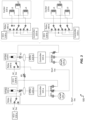
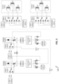
- FIG. 3 is an example schematic illustration of the engine start system 105 including components of the aircraft 100 in accordance with one or more embodiments of the present invention.
- Fig. 3 illustrates an example configuration of the engine start system 105 in accordance with one or more embodiments of the present invention.
- the engine start system 105 includes relay devices 140 (also referred to herein as relays or relay switches), switching devices K1 through K9, autotransformer rectifier units (ATRU) 125 (also referred to herein as autotransformer/rectifier circuitry), generator control units (GCUs) 130 (also referred to herein as generator control circuitry), exciters 120, and alternating current motor pumps (ACMPs) 145.
- relay devices 140 also referred to herein as relays or relay switches
- switching devices K1 through K9 switching devices K1 through K9
- autotransformer rectifier units (ATRU) 125 also referred to herein as autotransformer/rectifier circuitry
- generator control units (GCUs) 130 also referred to herein as generator control circuitry
- exciters 120 and alternating current motor pumps (ACMPs) 145.
- ACMPs alternating current motor pumps
- the controllers 115 are capable of controlling the start function of a VFSG 110 and regulating torque during the start sequence.
- the controller 115-a and controller 115-b are each capable of controlling the start function of VFSG 110-b (as will be described with reference to FIG. 3 ) or the start function of VFSG 110-a (as will be described with reference to FIG. 4 ).
- the controllers 115 are capable of additional functions associated with the aircraft 100 once the turbine engine 102 has been started.
- the relay devices 140 are single pole, double throw (SPDT) relays.
- switching devices K1 through K9 also referred to herein as contactors
- the ACMPs 145 and switching devices K1 through K9 may be implemented by switching system 132 described herein.
- a master controller (not illustrated) associated with the engine start system 105 may control and coordinate the switching of switchgear (e.g., including relay devices and switching devices K1 through K9) of the engine start system 105, example aspects of which are later described herein.
- the ATRUs 125 are capable of converting an AC input to a DC output.
- the ATRUs 125 are capable of converting AC power generated by the VFSGs 110 to DC power.
- the ATRUs 125 may be implemented in a power converter architecture of the engine start system 105.
- the GCUs 130 control respective VFSGs 110.
- GCU 130-a is a dedicated controller capable of controlling VFSG 110-a.
- Each GCU 130 is capable of providing voltage regulation and fault current limiting while a corresponding VFSG 110 is in generate mode.
- the GCUs 130 support the main engine start function of the aircraft 100.
- the ACMPs 145 are capable of providing hydraulic power (hydraulic pressure) in association with controlling VFSGs 110, engine thrust reversers, primary flight controls, landing gear, flaps/slats, and the like of the aircraft 100.
- VFSG 110-a is in a generate mode and VFSG 110-b is in a start mode.
- VFSG 110-a provides power (e.g., aircraft power 240) to the aircraft 100.
- the excitation of each exciter 120 is tied to one of available controllers 115 (e.g., controller 115-a or controller 115-b) providing the ability to vary the voltage and frequency to the exciter 120.
- controllers 115 e.g., controller 115-a or controller 115-b
- the excitation of exciter 120-a is tied to controller 115-a.
- the exciters 120 are three-phase exciters and each include inductors L1, L2, and L3.
- Relay device 140 and relay device 140-b are respectively implemented between two channels of the engine start system 105.
- the first channel is associated with VFSG 110-a
- the second channel is associated with VFSG 110-b.
- the systems and techniques described herein support changing the states of the relay devices 140 and switching devices K in association with providing start power from one side (e.g., the first channel) of the engine start system 105 to another side (e.g., the second channel) of the engine start system 105.
- Each relay device 140 is capable of coupling an exciter 120 to a motor controller 115 or a GCU 130.
- relay device 140 is capable of electrically coupling exciter 120-a to controller 115-b or GCU 130-a
- relay device 140-b is capable of electrically coupling exciter 120-b to controller 115-a or GCU 130-b.
- the systems and techniques described herein include using an auxiliary power source (not illustrated) for providing start power, in place of one of the VFSGs 110.
- the auxiliary power source is capable of providing start power to VFSG 110-b.
- the auxiliary power source may be an APU generator included in the aircraft 100.
- the auxiliary power source may be a battery on the aircraft 100 or a ground cart connected to the aircraft 100.
- the auxiliary power source is coupled to an AC bus (e.g., included at power bus 106) and is capable of providing power to the AC bus.
- the engine start system 105 can provide the power to either of the VFSGs 110 to start a corresponding turbine engine 102.
- a master controller included in the aircraft 100 controls and coordinates the switching devices K1 through K9 and relay devices 140.
- the master controller is capable of providing a start sequence to the associated controllers (e.g., GCU 130, a bus power control unit (BPCU) (not illustrated), motor controller 115) to close the specified switching devices K and relay devices to perform the start sequence.
- the BPCU controls bus configuration and engine health monitoring, provides control of the standby system, provides load management, and may serve as the electrical power system communication gateway with other systems of the aircraft 100.
- VFSG 110-a is in generate mode and VFSG 110-b is in start mode.
- the associated controllers close switching device K1, switching device K4, switching device K8, and switching device K9, and the remaining switching devices K2, K3, K5, K6, and K7 are in an open state.
- the associated controllers configure relay device 140-a such that exciter 120-a is coupled to GCU 130-a, and further, configure relay device 140-b such that exciter 120-b is coupled to controller 115-a.
- controller 115-a provides a three-phase controlled voltage and frequency to the exciter 120-b (e.g., via switching device K4) (at 'Start Exc').
- controller 115-b provides a three-phase controlled voltage and frequency to the three-phase main stator (e.g., stator portion 232 of FIG. 2 ) of VFSG 110-b, via switching device K8.
- the engine start system 105 supports providing a three-phase controlled voltage and frequency to the three-phase main stator of VFSG 110-b, via switching device K1, switching device K9, ATRU 125-b, controller 115-b, and switching device K8.
- the engine start system 105 may return the associated controllers to performing other suitable functions (e.g., functions different from the start sequence), and the engine start system 105 may return the switching devices K (e.g., switching device K1, switching device K4, switching device K8, and switching device K9) and the relay devices 140 to positions associated with a generate mode described herein (e.g., as described with reference to FIG. 5 ).
- the master controller may provide control signals associated with returning the associated controllers to performing the other functions and/or returning the contactors and relay devices to the positions associated with the generate mode.
- one phase of the corresponding three-phase exciter 120-a is shorted (e.g., at PMG stator coils 234 and/or exciter stator portion 236 of FIG. 2 ) to allow for normal 2-wire DC excitation to be provided by the corresponding GCU 130-a.
- An example in which both VFSGs 110 are in the generate mode is later described with reference to FIG. 5 .
- the VFSG 110-a is generating power traditionally as the VFSG 110-a is online and the GCU 130-a is providing control.
- starting the VFSG 110-a may be accomplished by starting the APU, which would allow for the APU generator to be the main power source for starting the VFSG 110-a.
- the APU generator may be started from an external power source.
- FIG. 4 illustrates a configuration of the engine start system 105 according to an example mode associated with starting the VFSG 110-b.
- VFSG 110-b is in a generate mode and VFSG 110-a is in a start mode.
- Aspects of the generate mode of VFSG 110-b and the start mode of VFSG 110-a are the same or similar to the example aspects described with reference to the generate mode of VFSG 110-a and the start mode of VFSG 110-b, and repeated descriptions are omitted for brevity.
- VFSG 110-b is in generate mode and VFSG 110-a is in start mode.
- the associated controllers close switching device K2, switching device K5, switching device K7, and switching device K9, and the remaining switching devices K1, K3, K4, K6, and K8 are in an open state.
- the associated controllers configure relay device 140 such that exciter 120-a is coupled to controller 115-b, and further, configure relay device 140-b such that exciter 120-b is coupled to GCU 130-b.
- controller 115-b provides a three-phase controlled voltage and frequency to the exciter 120-a (e.g., via switching device K7) (at 'Start Exc').
- controller 115-a provides a three-phase controlled voltage and frequency to the three-phase main stator of VFSG 110-a, via switching device K5. That is, for example, the engine start system 105 supports providing a three-phase controlled voltage and frequency to the three-phase main stator of VFSG 110-a, via switching device K2, switching device K9, ATRU 125-a, controller 115-a, and switching device K5.
- the engine start system 105 may return the associated controllers to performing other suitable functions (e.g., functions different from the start sequence), the engine start system 105 may return the switching devices K (e.g., switching device K1, switching device K4, switching device K8, and switching device K9) and the relay devices 140 to positions associated with a generate mode described herein (e.g., as described with reference to FIG. 5 ).
- the switching devices K e.g., switching device K1, switching device K4, switching device K8, and switching device K9
- the relay devices 140 e.g., switching device K1
- the relay devices 140 may return the switching devices K (e.g., switching device K1, switching device K4, switching device K8, and switching device K9) and the relay devices 140 to positions associated with a generate mode described herein (e.g., as described with reference to FIG. 5 ).
- the switching devices K e.g., switching device K1, switching device K4, switching device K8, and switching device K9
- the relay devices 140 e.g., switching device K
- FIG. 5 illustrates an example configuration of the engine start system 105 in accordance with one or more embodiments of the present invention.
- FIG. 5 illustrates an example in which VFSG 110-a and VFSG 110-b are both in generate mode.
- FIG. 5 illustrates an example of a mode of operation of the engine start system 105 to which the engine start system 105 may default or return when not in an engine start mode described with reference to FIGS. 3 and 4 .
- the associated controllers close switching device K1, switching device K2, switching device K3, and switching device K6, and the remaining connectors K4, K5, K7, K8, and K9 are in an open state.
- the associated controllers configure relay device 140 such that exciter 120-a is coupled to GCU 130-a, and further, configure relay device 140-b such that exciter 120-b is coupled to GCU 130-b.
- ACMP 145-a and ACMP 145-b may provide hydraulic power (hydraulic pressure) to other components (e.g., engine thrust reversers, primary flight controls, landing gear, flaps/slats, and the like) of the aircraft 100 based on power respectively generated by VFSG 110-a and VFSG 110-b.
- other components e.g., engine thrust reversers, primary flight controls, landing gear, flaps/slats, and the like
- the systems and techniques described herein provide several technical improvements compared to other engine start techniques.
- the example aspects of engine start system 105 as described herein provide for improved VFSG start performance and efficiency, increased start torque capability through field strengthening, and extended constant torque region through field weakening.
- the example aspects of engine start system 105 enable higher impedances in the main machine, which supports optimization (e.g., weight reduction) of the main machine of generator design.
- the example aspects of engine start system 105 enable optimization of the generator design through control of excitation frequency associated with engine startup.
- aspects of the engine start system 105 support improved design of an excitation system for various target frequencies (e.g., a fixed frequency, a narrow frequency range, and the like) because of the controller 115 capabilities for setting the excitation frequency.
- aspects of the engine start system 105 support reduced size and weight of an exciter, as the engine start system 105 supports increasing the excitation frequency to the high end of the frequency spectrum.
- engine start system 105 may be implemented with existing technology (e.g., motor controllers and system interconnects), which supports efficient integration into existing aircraft systems.
- existing technology e.g., motor controllers and system interconnects
- the example aspects of the engine start system 105 as described herein may be advantageously implemented without increasing the complexity of the GCU.
- some systems utilize a three phase exciter drive for excitation control in the controller (e.g., Integrated Converter Controller (ICC)).
- ICC Integrated Converter Controller
- three phase excitation is used during start mode and DC excitation is used for generate mode, such that several switches are idle during generate mode.
- Such systems implement output filters to accommodate the change in modes, which increases the complexity of the GCU.
- the techniques described herein enable to the use of existing or traditional GCUs with a DC excitation system.
- FIG. 6 is a schematic illustration 600 of a three-phase start exciter implemented in some other systems. Aspects of the exciter are described herein for illustrating shortcomings and drawbacks of the exciter of other systems compared to the systems and techniques described herein.
- the motor controller is injecting currents into the machine.
- the voltage (Va, Vb and Vc) is maintained to be greater than the back EMF (E) and the voltage drop due to Rph and Lph.
- E back EMF
- the back EMF will increase with speed because the excitation source is a fixed voltage, and at the time of the start the excitation source will be a fixed frequency.
- the exciter is a wound rotor induction machine running at negative slip.
- increasing torque capability over the speed range is achieved by increasing VDC or reducing Lph, because the Back-EMF (E) is uncontrolled and not linear.
- E Back-EMF
- the slip of the machine changes such that the back EMF increases as the speed increases.
- the variable input frequency associated with the back EMF creates the non-linear behavior in the excitation system.
- the back EMF of the system changes not only with excitation frequency, but also as the speed of the unit increases. Accordingly, other approaches size the exciter for the low excitation frequency and low speed to produce enough break away torque at zero speed.
- Some compromises include a larger exciter due to sizing for low excitation frequency.
- Some compromises include a motor controller which utilizes field weakening techniques, at the cost of additional input power.
- the additional input power is not available, then such approaches include one or both of following actions in order to achieve the start torque requirements: the main machine size is increased in order to lower the commutating reactance of the machine, or the bus voltage to the motor controller is increased.
- the operations may be performed in a different order than the order shown, or the operations may be performed in different orders or at different times. Certain operations may also be left out of the method, one or more operations may be repeated, or other operations may be added to the methods.
- first and second may be used to reference various components regardless of importance and/or order and are used to distinguish a component from another without limiting the components.
- a first VFSG and a second VFSG may indicate devices different from each other regardless of the order or importance of the devices.
- a first component may be denoted a second component, and vice versa without departing from the scope of the present invention.
- a first voltage (or frequency) may be denoted a second voltage (or frequency), and vice versa without departing from the scope of the present invention.
Landscapes
- Engineering & Computer Science (AREA)
- Power Engineering (AREA)
- Chemical & Material Sciences (AREA)
- Combustion & Propulsion (AREA)
- Aviation & Aerospace Engineering (AREA)
- Mechanical Engineering (AREA)
- General Engineering & Computer Science (AREA)
- Control Of Eletrric Generators (AREA)
Abstract
An engine start system for an aircraft includes a first variable frequency start generator (VFSG) (110-a) including a first exciter (120-a) and a first stator, a second VFSG (110-b) including a second exciter (120-b) and a second stator, a first motor controller (115-a) and a second motor controller (115-b), and a switching system (132). The switching system is configured to operatively connect the first motor controller to the first stator or the second exciter and operatively connect the second motor controller to the first exciter or the second stator. In a first mode of operation, the first motor controller is operatively connected to the second exciter, the second motor controller is operatively connected to the second stator, the first VFSG generates power, the first motor controller provides a first controlled voltage and frequency to the second exciter, and the second motor controller provides a second controlled voltage and frequency to the second stator.
Description
- The subject matter disclosed herein generally relates to engine start systems for gas turbine engines and, more particularly, to engine start systems used on aircraft.
- Vehicles, such as aircraft, employ starter/generators for both starting the aircraft engine and generating electrical power for aircraft electrical systems subsequent to starting. A controller commonly cooperates with the starter/generator to convert power flowing to the starter/generator. For example, during engine starting (start mode) the controller generally converts external power into a form suitable for rotating the gas turbine engine rotor using the starter/generator. Once the gas turbine engine has started, the controller then causes the starter/generator to be fed power in a form so that the starter/generator operates in a manner so that it generates power. This operation is referred to as a generate mode herein.
- One example of a starter/generator is a variable frequency starter generator (VFSG). Some VFSG systems are capable of operating in both the two above referred start and generate mode. A typical VFSG includes a three-phase start exciter to enable excitation at zero to low speeds. During start mode, three phase AC power is applied to the VFSG exciter coils to energize the main field. In such a case, the exciter coils are directly hooked up to the 235Vrms aircraft AC bus, which results in the VFSG getting 235 VACL-N voltage at a frequency ranging from 360 Hz to 800 Hz. While this can work well for starting, when in the generate mode, providing three phase power to the exciter coils can result in the back EMF increasing.
- Techniques for providing excitation power (e.g., current/voltage) to a VFSG are desired which address drawbacks associated with other approaches.
- An engine start system for an aircraft is disclosed. The engine start system includes: a first variable frequency start generator (VFSG) that includes a first exciter and a first stator; a second VFSG that includes a second exciter and a second stator; a first motor controller and a second motor controller; and a switching system. The switching system is configured to: operatively connect the first motor controller to the first stator or the second exciter; and operatively connect the second motor controller to the first exciter or the second stator. In a first mode of operation of the engine start system, the switching system is configured such that: the first motor controller is operatively connected to the second exciter based on a first switch configuration of the switching system; the second motor controller is operatively connected to the second stator based on the first switch configuration; and the first VFSG generates power. In the first mode of operation of the engine start system, the first motor controller provides a first controlled voltage and frequency to the second exciter based on at least one of: the power generated by the first VFSG; and other power generated by a power source different from the first VFSG; and the second motor controller provides a second controlled voltage and frequency to the second stator based on the power generated by the first VFSG.
- In some embodiments, in a second mode of operation of the engine start system, the switching system is configured such that: the first motor controller is coupled to the first stator based on a second switch configuration of the switching system; the second motor controller is coupled to the first exciter based on the second switch configuration; the second VFSG generates second power; the second motor controller provides a third controlled voltage and frequency to the first exciter based on the second power generated by the second VFSG; and the first motor controller provides a fourth controlled voltage and frequency to the first VFSG based on the second power generated by the second VFSG.
- In any one or combination of the foregoing embodiments, in the first mode of operation of the engine start system, the switching system is configured such that: the first exciter is electrically coupled to first generator control circuitry of the engine start system; and the first VFSG generates the power based on a DC excitation of the first exciter by the first generator control circuitry.
- In any one or combination of the foregoing embodiments, in a second mode of operation of the engine start system, the switching system is configured such that: the first exciter is electrically coupled to first generator control circuitry of the engine start system; the first VFSG generates the power based on a DC excitation of the first exciter by the first generator control circuitry; the second exciter is electrically coupled to second generator control circuitry of the engine start system; and the second VFSG generates second power based on a DC excitation of the second exciter by the second generator control circuitry.
- In any one or combination of the foregoing embodiments, the first controlled voltage and frequency and the second controlled voltage and frequency are each a three-phase controlled voltage and frequency.
- In any one or combination of the foregoing embodiments, a first configuration of the switching system is associated with the first mode.
- In any one or combination of the foregoing embodiments, the switching system is configured to: operatively connect the first motor controller to the first VFSG or the second VFSG; and operatively connect the second motor controller to the first VFSG or the second VFSG.
- In any one or combination of the foregoing embodiments, the first exciter and the second exciter are each a three-phase exciter, and where in the first mode of operation of the engine start system, the switching system is configured such that: the first exciter is in a direct current (DC) excitation mode; and the second exciter is in a three-phase excitation mode.
- Also disclosed is a method of controlling an engine start system of an aircraft including a first VFSG and a second VFSG. The method includes, in a first mode of operation of the engine start system: operatively connecting a first motor controller to an exciter of the engine start system, based on a first switch configuration associated with the first mode of operation, where: the first motor controller is included in the engine start system; and the exciter is included in the second VFSG. The method includes: operatively connecting a second motor controller to a stator of the second VFSG based on the first switch configuration; and generating, by the first VFSG, power. The method includes providing, by the first motor controller, a first controlled voltage and frequency to the exciter included in the second VFSG, based on at least one of: the power generated by the first VFSG; and other power generated by a power source different from the first VFSG. The method includes providing, by the second motor controller, a second controlled voltage and frequency to the stator of the second VFSG based on the power generated by the first VFSG, where the first mode of operation is associated with starting at least one gas turbine engine of the aircraft.
- In some embodiments, in a second mode of operation of the engine start system: operatively connecting the second motor controller to an exciter included in the first VFSG, based on a second switch configuration associated with the second mode of operation; operatively connecting the first motor controller to a stator of the first VFSG based on the second switch configuration; generating, by the second VFSG, second power; providing, by the second motor controller, a third controlled voltage and frequency to the exciter included in the first VFSG, based on the second power generated by the second VFSG; and providing, by the first motor controller, a fourth controlled voltage and frequency to the first VFSG based on the second power generated by the second VFSG, where the second mode of operation is associated with starting the at least one gas turbine engine of the aircraft.
- In any one or combination of the foregoing embodiments, the method further includes: electrically coupling the exciter to first generator control circuitry of the engine start system based on the first switching configuration; and controlling, by the first generator control circuitry, a DC excitation of the first exciter, where the first VFSG generates the power based on the DC excitation of the exciter.
- In any one or combination of the foregoing embodiments, the method further includes, in a second mode of operation of the engine start system: electrically coupling the exciter to first generator control circuitry of the engine start system based on a second switching configuration associated with the second mode of operation; controlling, by the first generator control circuitry, a DC excitation of the exciter, where the first VFSG generates the power based on the DC excitation of the exciter; electrically coupling an exciter included in the first VFSG to second generator control circuitry of the engine start system based on the second switch configuration; and controlling, by the second generator control circuitry, a DC excitation of the exciter included in the first VFSG, where the second VFSG generates second power based on the DC excitation of the exciter included in the first VFSG.
- In any one or combination of the foregoing embodiments, the first controlled voltage and frequency and the second controlled voltage and frequency are each a three-phase controlled voltage.
- In any one or combination of the foregoing embodiments, the method further includes controlling switching circuitry based on the first mode and the first switching configuration, where operatively connecting the first motor controller and the exciter, operatively connecting the second motor controller to the second VFSG, or both is based on controlling the switching circuitry.
- Also disclosed is an aircraft electrical architecture including: a VFSG; an exciter; and at least one gas turbine engine. The VFSG is operable to generate power in a first mode of operation associated with the aircraft electrical architecture. The VFSG is operable to generate a force associated with rotating a shaft included in the at least one gas turbine engine in a second mode of operation associated with the aircraft electrical architecture, based on second power provided by an auxiliary power source associated with the aircraft electrical architecture.
- In any one or combination of the foregoing embodiments, the auxiliary power source includes at least one of: a second VFSG included in the aircraft electrical architecture; and a power generator different from the second VFSG.
- In any one or combination of the foregoing embodiments: the second VFSG is operable to generate a second force associated with rotating the shaft in the first mode of operation, based on the power generated by the first VFSG or third power provided by a second auxiliary power source external to the aircraft electrical architecture; and the second VFSG is operable to generate the second power in the second mode of operation.
- In any one or combination of the foregoing embodiments, the aircraft electrical architecture further includes a motor controller, where in the first mode of operation: the motor controller is operable to provide a controlled voltage and frequency to the exciter based on the power generated by the VFSG, where the exciter is included in the second VFSG; and the second VFSG generates a second force associated with rotating the shaft in the first mode, based on the controlled voltage.
- In any one or combination of the foregoing embodiments, the aircraft electrical architecture further includes a motor controller, where in the second mode of operation: the motor controller is operable to provide a controlled voltage and frequency to the exciter based on the second power provided by the auxiliary power source; and the second VFSG generates a second force associated with rotating the shaft in the second mode, based on the controlled voltage.
- In any one or combination of the foregoing embodiments, the aircraft electrical architecture further includes: a motor controller; and a starter switching system configured to operatively connect the motor controller to the exciter or a second exciter, where the exciter is included in a second VFSG of the aircraft electrical architecture, and the second exciter is included in the first VFSG.
- The following descriptions should not be considered limiting in any way. With reference to the accompanying drawings, like elements are numbered alike:
-
FIG. 1A is a schematic illustration of an aircraft that can incorporate various embodiments of the present invention. -
FIG. 1B is a simplified block diagram of an engine start system that can incorporate various embodiments of the present invention. -
FIG. 2 shows a simplified example of a VFSG described herein. -
FIG. 3 illustrates a configuration of an engine start system in accordance with one or more embodiments of the present invention. -
FIG. 4 illustrates a configuration of an engine start system according to an example mode in accordance with one or more embodiments of the present invention. -
FIG. 5 illustrates an example configuration of the engine start system in accordance with one or more embodiments of the present invention. -
FIG. 6 is a schematic illustration of a three-phase start exciter implemented in some other systems. - A detailed description of one or more embodiments of the disclosed apparatus and method are presented herein by way of exemplification and not limitation with reference to the Figures.
- According to one or more embodiments of the present invention, an electrical system architecture is provided that supports performing an engine start using multiple motor controllers, and the engine start techniques provide improved control of a start sequence to the VFSG.
-
FIG. 1A is a schematic illustration of an aircraft that can incorporate various embodiments of the present invention. Referring toFIG. 1A , a vehicle, e.g., anaircraft 100, is shown. Theaircraft 100 includes the starter/generator arrangement 101, a gas turbine engine 102 (also referred to herein as a turbine engine or a turbine), and anelectrical system 104. - The
electrical system 104 includes apower bus 106, apower source 108, and an electrical load 20. Thepower bus 106 electrically connects the starter/generator arrangement 101 to thepower source 108 and theVFSG 110. It is also contemplated that thepower bus 106 communicates from thepower source 108 to theVFSG 110 during the start mode. Thepower source 108 can be either DC or AC. In the event it is AC it can provide differing voltage values. To that end, thepower source 108 can be a battery in one embodiment and a generator in another. - Further details of the
VFSG 110 are described below but in general, thecontroller 115 includes one or more circuits that can convert input power (e.g., from the power source or a permanent magnet generator (PMG) that is part of the VFSG 110) into a form that is useful to operate theVFSG 110 in both start and generate modes. - The
gas turbine engine 102 includes afan section 56, acompressor section 55, acombustor section 57, and aturbine section 58. The fan is supported for rotation about a rotation axis R and is operatively associated with theturbine section 58 by ashaft 59. Although a particular gas turbine engine arrangement is shown and described herein it is to be understood and appreciated that gas turbines having other arrangements can also benefit from the present invention. - The starter/
generator arrangement 101 generally includes aVFSG 110, acontroller 115 and an output shaft 117 (also referred to herein as a rotor 117). During start up, the excitation controller provides three phase current to the field coils/windings of theVFSG 110. This causes theshaft 117 to rotate and, thus, causes theturbine shaft 59 to begin rotating so that it can start. Once thegas turbine engine 102 is operating, it produces rotational energy that can then be provided back to theVFSG 110 so that it can generate electricity to be provided to other parts of the aircraft (e.g., the running the VFSG can serve to generate electrical power due to rotational energy). - In the illustrated example the
gas turbine engine 102 includes anaccessory gearbox 103. Theaccessory gearbox 103 mechanically connects theVFSG 110 and thegas turbine engine 102. Subsequent to starting, e.g., when theVFSG 110 is in the generate mode, theaccessory gearbox 103 communicates rotational energy to theVFSG 110. As noted above, theVFSG 110 converts the rotational energy into the electrical power. Further, during startup, thegear box 103 receives rotational energy from theVFSG 110 via theoutput shaft 117 and provides it to thegas turbine engine 102 to start thegas turbine engine 102. -
FIG. 1B is a simplified block diagram of anengine start system 105 of theaircraft 100 that can incorporate various embodiments of the present invention. Theengine start system 105 is supportive of startup modes and a generate modes described herein. Theengine start system 105 includesVFSGs 110 and a switching system 132 (also referred to herein as a starter switching system). TheVFSGs 110 are mechanically coupled toaccessory gearbox 103. Components of theswitching system 132 may be referred to as switchgear herein. Theengine start system 105 may include other components of theaircraft 100, which are not illustrated herein for purposes of not obstructing from other aspects of the present invention. - Each of the
VFSGs 110 includes anexciter 120. Each VFSG may be coupled to acontroller 115. For example, VFSG 110-a includes controller 115-a and exciter 120-a, and VFSG 110-b includes controller 115-b and exciter 120-b. Thecontrollers 115 may also be referred to herein as common motor start controllers (CMSCs), common motor controllers, or motor controllers. Theexciters 120 may also be referred to herein as excitation circuitry or VFSG exciters. In one or more embodiments, theswitching system 132 is capable of operatively connecting the controller 115-a to the exciter 120-a or the exciter 120-b, and further, operatively connecting the controller 115-b to the exciter 120-a or the exciter 120-b. - Aspects supportive of starting the
gas turbine engines 102 of theaircraft 100 based on different modes of theVFSGs 110 and different switch configurations of theswitching system 132 are later described herein with reference to theFIGS. 3 through 5 . In one or more embodiments, theswitching system 132 includes multiple relay devices and switching devices, example aspects of which are later described herein with reference toFIGS. 3 through 5 . -
FIG. 2 shows a simplified example 200 of a VFSG 110 (e.g., VFSG 110-b) described herein. TheVFSG 110 is connected tocontroller 115. Thecontroller 115 can be any controller disclosed herein and can operate to provide current to various portions of the exciter field winding(s) during both start and generate modes. -
VFSG 110 includes arotor portion 224 andstator portion 232. Therotor portion 224 includes apermanent magnet portion 226, anexciter rotor portion 228 and a mainfield rotor portion 230. Thestator portion 232 includes a PMG stator coils 234,exciter stator portion 236, and main field stator windings 238. - As shown, the
controller 115 can receive power fromaircraft power 240. Theaircraft power 240 can be AC or DC. For example,aircraft power 240 can be provided by another VFSG 110 (e.g., VFSG 110-a), a battery on the aircraft, power from a ground cart connected to the aircraft, or an auxiliary power unit (APU). In some cases, another VFSG 110 (e.g., VFSG 110-a) providing power may be referred to as an auxiliary start generator (ASG). - During start up, the
controller 115 is configured such that thecontroller 115 is capable of providing three phase power to theexciter stator portion 236. While theexciter stator portion 236 is illustrated as having a three winding, theexciter stator portion 236 can operate in the generate mode in which only one phase is powered. Operating in the generate mode in which only one phase is powered causes a rotating magnetic field that interacts with three-phase coils in theexciter rotor portion 228. The interaction will induce AC voltage in the exciter rotor windings. This induced AC voltage is then rectified to DC (on the rotor 117), which is then applied to the rotor winding of the main machine. Concurrently, theseparate motor controller 280 applies appropriate high voltage/current on the V(A), V(B), V(C) stator terminals of the main machine. The interaction between the main stator rotating magnetic field produced by the three-phase AC voltages applied by themotor controller 280, and the DC magnetic field on the main rotor causes therotor 117 to rotate. This rotation can be used to get thegas turbine engine 102 ofFIG. 1A to begin rotation and then, eventually, started. - After the
gas turbine engine 102 has reached an operation speed, thecontroller 115 can operate theVFSG 110 in the generate mode. In the generate mode, the turbine engine 102 (via rotor 117) provides mechanical energy torotor portion 224, causingpermanent magnet portion 226,exciter rotor portion 228, and mainfield rotor portion 230 to rotate. The rotation ofpermanent magnet portion 226 generates an alternating current (AC) voltage in PMG stator coils 234, labeled Van1, Vbn1, and Vcn1. The outputs of PMG stator coils 234 are provided tocontroller 115, which rectifies the AC input and provides a DC excitation current toexciter stator portion 236. These output voltages may collectively be referred to `VPMG out.' For convenience, thePMG portions 226/234 can be referred to as a PMG herein. - Based on the magnitude of the excitation current provided to
exciter stator portion 236, theexciter rotor portion 228 generates an AC output that is rectified and provided to mainfield rotor portion 230 to couple the exciter stator current to the main field rotor current by rotation. In response to the rotating field established by mainfield rotor portion 230, and in particular,coil 231, the main field stator windings 238 generate a variable frequency (based on the speed of the rotor 117) main AC voltages labeled Van3, Vbn3, and Vcn3. The main AC voltages Van3, Vbn3, and Vcn3 may then be provided as an output in which they are labeled AC output voltages V(A), V(B), and V(C). For convenience,exciter rotor portion 228, the PMG stator coils 234,exciter stator portion 236, main field stator windings 238, can be referred to as anexciter 120. For example, aspects of theexciter rotor portion 228, the PMG stator coils 234,exciter stator portion 236, main field stator windings 238 may be implemented by an exciter 120 (e.g., exciter 120-a, exciter 120-b) as described herein with reference toFIGS. 1B ,3 ,4 , and5 . -
FIG. 3 is an example schematic illustration of theengine start system 105 including components of theaircraft 100 in accordance with one or more embodiments of the present invention.Fig. 3 illustrates an example configuration of theengine start system 105 in accordance with one or more embodiments of the present invention. - Referring to
FIG. 3 , theengine start system 105 includes relay devices 140 (also referred to herein as relays or relay switches), switching devices K1 through K9, autotransformer rectifier units (ATRU) 125 (also referred to herein as autotransformer/rectifier circuitry), generator control units (GCUs) 130 (also referred to herein as generator control circuitry),exciters 120, and alternating current motor pumps (ACMPs) 145. - In some aspects, the
controllers 115 are capable of controlling the start function of aVFSG 110 and regulating torque during the start sequence. In an example, the controller 115-a and controller 115-b are each capable of controlling the start function of VFSG 110-b (as will be described with reference toFIG. 3 ) or the start function of VFSG 110-a (as will be described with reference toFIG. 4 ). Thecontrollers 115 are capable of additional functions associated with theaircraft 100 once theturbine engine 102 has been started. - In one or more embodiments, the
relay devices 140 are single pole, double throw (SPDT) relays. In one or more embodiments, switching devices K1 through K9 (also referred to herein as contactors) are mechanical switches. TheACMPs 145 and switching devices K1 through K9 may be implemented by switchingsystem 132 described herein. A master controller (not illustrated) associated with theengine start system 105 may control and coordinate the switching of switchgear (e.g., including relay devices and switching devices K1 through K9) of theengine start system 105, example aspects of which are later described herein. - The
ATRUs 125 are capable of converting an AC input to a DC output. For example, theATRUs 125 are capable of converting AC power generated by theVFSGs 110 to DC power. TheATRUs 125 may be implemented in a power converter architecture of theengine start system 105. - The
GCUs 130 controlrespective VFSGs 110. In an example, GCU 130-a is a dedicated controller capable of controlling VFSG 110-a. EachGCU 130 is capable of providing voltage regulation and fault current limiting while acorresponding VFSG 110 is in generate mode. TheGCUs 130 support the main engine start function of theaircraft 100. - The
ACMPs 145 are capable of providing hydraulic power (hydraulic pressure) in association with controllingVFSGs 110, engine thrust reversers, primary flight controls, landing gear, flaps/slats, and the like of theaircraft 100. - An example of an engine start mode in accordance with one or more embodiments of the present invention is now described with reference to
FIG. 3 . In the example, VFSG 110-a is in a generate mode and VFSG 110-b is in a start mode. According to example aspects of the engine start mode described with reference toFIG. 3 , VFSG 110-a provides power (e.g., aircraft power 240) to theaircraft 100. - In one or more embodiments, the excitation of each
exciter 120 is tied to one of available controllers 115 (e.g., controller 115-a or controller 115-b) providing the ability to vary the voltage and frequency to theexciter 120. Referring to the example ofFIG. 3 , the excitation of exciter 120-a is tied to controller 115-a. In one or more embodiments, theexciters 120 are three-phase exciters and each include inductors L1, L2, and L3. -
Relay device 140 and relay device 140-b are respectively implemented between two channels of theengine start system 105. In an example, the first channel is associated with VFSG 110-a, and the second channel is associated with VFSG 110-b. The systems and techniques described herein support changing the states of therelay devices 140 and switching devices K in association with providing start power from one side (e.g., the first channel) of theengine start system 105 to another side (e.g., the second channel) of theengine start system 105. Eachrelay device 140 is capable of coupling anexciter 120 to amotor controller 115 or aGCU 130. For example,relay device 140 is capable of electrically coupling exciter 120-a to controller 115-b or GCU 130-a, and relay device 140-b is capable of electrically coupling exciter 120-b to controller 115-a or GCU 130-b. - Additionally, or alternatively, during ground operations, the systems and techniques described herein include using an auxiliary power source (not illustrated) for providing start power, in place of one of the
VFSGs 110. For example, with reference to the example ofFIG. 3 , the auxiliary power source is capable of providing start power to VFSG 110-b. In one or more embodiments, the auxiliary power source may be an APU generator included in theaircraft 100. In one or more embodiments, the auxiliary power source may be a battery on theaircraft 100 or a ground cart connected to theaircraft 100. In an example, the auxiliary power source is coupled to an AC bus (e.g., included at power bus 106) and is capable of providing power to the AC bus. Theengine start system 105 can provide the power to either of theVFSGs 110 to start a correspondingturbine engine 102. - A master controller (not illustrated) included in the
aircraft 100 controls and coordinates the switching devices K1 through K9 andrelay devices 140. The master controller is capable of providing a start sequence to the associated controllers (e.g.,GCU 130, a bus power control unit (BPCU) (not illustrated), motor controller 115) to close the specified switching devices K and relay devices to perform the start sequence. The BPCU controls bus configuration and engine health monitoring, provides control of the standby system, provides load management, and may serve as the electrical power system communication gateway with other systems of theaircraft 100. - In the example of
FIG. 3 , VFSG 110-a is in generate mode and VFSG 110-b is in start mode. The associated controllers close switching device K1, switching device K4, switching device K8, and switching device K9, and the remaining switching devices K2, K3, K5, K6, and K7 are in an open state. The associated controllers configure relay device 140-a such that exciter 120-a is coupled to GCU 130-a, and further, configure relay device 140-b such that exciter 120-b is coupled to controller 115-a. - Accordingly, for example, controller 115-a provides a three-phase controlled voltage and frequency to the exciter 120-b (e.g., via switching device K4) (at 'Start Exc'). In the example, controller 115-b provides a three-phase controlled voltage and frequency to the three-phase main stator (e.g.,
stator portion 232 ofFIG. 2 ) of VFSG 110-b, via switching device K8. That is, for example, theengine start system 105 supports providing a three-phase controlled voltage and frequency to the three-phase main stator of VFSG 110-b, via switching device K1, switching device K9, ATRU 125-b, controller 115-b, and switching device K8. - Once the start sequence has been completed, the
engine start system 105 may return the associated controllers to performing other suitable functions (e.g., functions different from the start sequence), and theengine start system 105 may return the switching devices K (e.g., switching device K1, switching device K4, switching device K8, and switching device K9) and therelay devices 140 to positions associated with a generate mode described herein (e.g., as described with reference toFIG. 5 ). For example, the master controller may provide control signals associated with returning the associated controllers to performing the other functions and/or returning the contactors and relay devices to the positions associated with the generate mode. - In one or more embodiments, for the VFSG 110-a in generate mode, one phase of the corresponding three-phase exciter 120-a is shorted (e.g., at PMG stator coils 234 and/or
exciter stator portion 236 ofFIG. 2 ) to allow for normal 2-wire DC excitation to be provided by the corresponding GCU 130-a. An example in which bothVFSGs 110 are in the generate mode is later described with reference toFIG. 5 . - As described with reference to
FIG. 3 , the VFSG 110-a is generating power traditionally as the VFSG 110-a is online and the GCU 130-a is providing control. In one or more embodiments, starting the VFSG 110-a may be accomplished by starting the APU, which would allow for the APU generator to be the main power source for starting the VFSG 110-a. In some examples, the APU generator may be started from an external power source. -
FIG. 4 illustrates a configuration of theengine start system 105 according to an example mode associated with starting the VFSG 110-b. - For example, with reference to
FIG. 4 , VFSG 110-b is in a generate mode and VFSG 110-a is in a start mode. Aspects of the generate mode of VFSG 110-b and the start mode of VFSG 110-a are the same or similar to the example aspects described with reference to the generate mode of VFSG 110-a and the start mode of VFSG 110-b, and repeated descriptions are omitted for brevity. - An example of an engine start mode in accordance with one or more embodiments of the present invention is now described with reference to
FIG. 4 . In the example ofFIG. 4 , VFSG 110-b is in generate mode and VFSG 110-a is in start mode. The associated controllers close switching device K2, switching device K5, switching device K7, and switching device K9, and the remaining switching devices K1, K3, K4, K6, and K8 are in an open state. The associated controllers configurerelay device 140 such that exciter 120-a is coupled to controller 115-b, and further, configure relay device 140-b such that exciter 120-b is coupled to GCU 130-b. - Accordingly, for example, controller 115-b provides a three-phase controlled voltage and frequency to the exciter 120-a (e.g., via switching device K7) (at 'Start Exc'). In the example, controller 115-a provides a three-phase controlled voltage and frequency to the three-phase main stator of VFSG 110-a, via switching device K5. That is, for example, the
engine start system 105 supports providing a three-phase controlled voltage and frequency to the three-phase main stator of VFSG 110-a, via switching device K2, switching device K9, ATRU 125-a, controller 115-a, and switching device K5. - Once the start sequence has been completed, the
engine start system 105 may return the associated controllers to performing other suitable functions (e.g., functions different from the start sequence), theengine start system 105 may return the switching devices K (e.g., switching device K1, switching device K4, switching device K8, and switching device K9) and therelay devices 140 to positions associated with a generate mode described herein (e.g., as described with reference toFIG. 5 ). In one or more embodiments, for the VFSG 110-b in generate mode, one phase of the corresponding three-phase exciter 120-b is shorted to allow for normal 2-wire DC excitation to be provided by the corresponding GCU 130-b. -
FIG. 5 illustrates an example configuration of theengine start system 105 in accordance with one or more embodiments of the present invention.FIG. 5 illustrates an example in which VFSG 110-a and VFSG 110-b are both in generate mode. - In some cases,
FIG. 5 illustrates an example of a mode of operation of theengine start system 105 to which theengine start system 105 may default or return when not in an engine start mode described with reference toFIGS. 3 and4 . Referring toFIG. 5 , the associated controllers close switching device K1, switching device K2, switching device K3, and switching device K6, and the remaining connectors K4, K5, K7, K8, and K9 are in an open state. The associated controllers configurerelay device 140 such that exciter 120-a is coupled to GCU 130-a, and further, configure relay device 140-b such that exciter 120-b is coupled to GCU 130-b. - In an example, ACMP 145-a and ACMP 145-b may provide hydraulic power (hydraulic pressure) to other components (e.g., engine thrust reversers, primary flight controls, landing gear, flaps/slats, and the like) of the
aircraft 100 based on power respectively generated by VFSG 110-a and VFSG 110-b. - The systems and techniques described herein provide several technical improvements compared to other engine start techniques. The example aspects of
engine start system 105 as described herein provide for improved VFSG start performance and efficiency, increased start torque capability through field strengthening, and extended constant torque region through field weakening. The example aspects ofengine start system 105 enable higher impedances in the main machine, which supports optimization (e.g., weight reduction) of the main machine of generator design. The example aspects ofengine start system 105 enable optimization of the generator design through control of excitation frequency associated with engine startup. - Aspects of the
engine start system 105 support improved design of an excitation system for various target frequencies (e.g., a fixed frequency, a narrow frequency range, and the like) because of thecontroller 115 capabilities for setting the excitation frequency. Aspects of theengine start system 105 support reduced size and weight of an exciter, as theengine start system 105 supports increasing the excitation frequency to the high end of the frequency spectrum. - The example aspects of
engine start system 105 may be implemented with existing technology (e.g., motor controllers and system interconnects), which supports efficient integration into existing aircraft systems. - The example aspects of the
engine start system 105 as described herein may be advantageously implemented without increasing the complexity of the GCU. For example, some systems utilize a three phase exciter drive for excitation control in the controller (e.g., Integrated Converter Controller (ICC)). In such systems, three phase excitation is used during start mode and DC excitation is used for generate mode, such that several switches are idle during generate mode. Such systems implement output filters to accommodate the change in modes, which increases the complexity of the GCU. In contrast, the techniques described herein enable to the use of existing or traditional GCUs with a DC excitation system. -
FIG. 6 is aschematic illustration 600 of a three-phase start exciter implemented in some other systems. Aspects of the exciter are described herein for illustrating shortcomings and drawbacks of the exciter of other systems compared to the systems and techniques described herein. - In some other techniques which incorporate a VFSG for producing the force associated with starting a turbine engine, during start the motor controller is injecting currents into the machine. In order to maintain torque, the voltage (Va, Vb and Vc) is maintained to be greater than the back EMF (E) and the voltage drop due to Rph and Lph. In some VFSG systems, the back EMF will increase with speed because the excitation source is a fixed voltage, and at the time of the start the excitation source will be a fixed frequency.
- The exciter is a wound rotor induction machine running at negative slip. In the system illustrated at
FIG. 6 , increasing torque capability over the speed range is achieved by increasing VDC or reducing Lph, because the Back-EMF (E) is uncontrolled and not linear. Because the input voltage to the exciter is fixed, the slip of the machine changes such that the back EMF increases as the speed increases. The variable input frequency associated with the back EMF creates the non-linear behavior in the excitation system. As a result, the back EMF of the system changes not only with excitation frequency, but also as the speed of the unit increases. Accordingly, other approaches size the exciter for the low excitation frequency and low speed to produce enough break away torque at zero speed. However, when the machine is excited at high frequency, this leads to extremely high back EMFs as the speed increases. As a result of the high back EMFs, the motor controller cannot overcome impedance of the machine and the back EMF, resulting is degraded torque capability as speed increases - Such architectures associated with other approaches force multiple compromises. Some compromises include a larger exciter due to sizing for low excitation frequency. Some compromises include a motor controller which utilizes field weakening techniques, at the cost of additional input power. However, if the additional input power is not available, then such approaches include one or both of following actions in order to achieve the start torque requirements: the main machine size is increased in order to lower the commutating reactance of the machine, or the bus voltage to the motor controller is increased.
- In the descriptions of the methods herein, the operations may be performed in a different order than the order shown, or the operations may be performed in different orders or at different times. Certain operations may also be left out of the method, one or more operations may be repeated, or other operations may be added to the methods.
- The term "about" is intended to include the degree of error associated with measurement of the particular quantity based upon the equipment available at the time of filing the application.
- The terminology used herein is for the purpose of describing particular embodiments only and is not intended to be limiting of the present invention. As used herein, the singular forms "a", "an" and "the" are intended to include the plural forms as well, unless the context clearly indicates otherwise. It will be further understood that the terms "comprises" and/or "comprising," when used in this specification, specify the presence of stated features, integers, steps, operations, elements, and/or components, but do not preclude the presence or addition of one or more other features, integers, steps, operations, element components, and/or groups thereof.
- As used herein, the terms "first" and "second" may be used to reference various components regardless of importance and/or order and are used to distinguish a component from another without limiting the components. For example, a first VFSG and a second VFSG may indicate devices different from each other regardless of the order or importance of the devices. For example, a first component may be denoted a second component, and vice versa without departing from the scope of the present invention. A first voltage (or frequency) may be denoted a second voltage (or frequency), and vice versa without departing from the scope of the present invention.
- While the present invention has been described with reference to an exemplary embodiment or embodiments, it will be understood by those skilled in the art that various changes may be without departing from the scope of the invention as defined by the claims.
Claims (15)
- An engine start system comprising:a first variable frequency start generator, VFSG, (110-a) that includes a first exciter (120-a) and a first stator;a second VFSG (110-b) that includes a second exciter (120-b) and a second stator;a first motor controller (115-a) and a second motor controller (115-b); anda switching system (132) configured to:operatively connect the first motor controller to the first stator or the second exciter; andoperatively connect the second motor controller to the first exciter or the second stator,wherein in a first mode of operation of the engine start system, the switching system is configured such that:the first motor controller is operatively connected to the second exciter based on a first switch configuration of the switching system;the second motor controller is operatively connected to the second stator based on the first switch configuration;the first VFSG generates power;the first motor controller provides a first controlled voltage and frequency to the second exciter based on at least one of:the power generated by the first VFSG; andother power generated by a power source different from the first VFSG; andthe second motor controller provides a second controlled voltage and frequency to the second stator based on the power generated by the first VFSG.
- The engine start system of claim 1, wherein in a second mode of operation of the engine start system, the switching system is configured such that:the first motor controller (115-a) is coupled to the first stator based on a second switch configuration of the switching system;the second motor controller (115-b) is coupled to the first exciter based on the second switch configuration;the second VFSG (110-b) generates second power;the second motor controller provides a third controlled voltage and frequency to the first exciter based on the second power generated by the second VFSG; andthe first motor controller provides a fourth controlled voltage and frequency to the first VFSG (110-a) based on the second power generated by the second VFSG.
- The engine start system of claim 1 or 2, wherein in the first mode of operation of the engine start system, the switching system is configured such that:the first exciter is electrically coupled to first generator control circuitry of the engine start system; andthe first VFSG generates the power based on a DC excitation of the first exciter by the first generator control circuitry.
- The engine start system of claim 1, wherein in a second mode of operation of the engine start system, the switching system is configured such that:the first exciter is electrically coupled to first generator control circuitry of the engine start system;the first VFSG generates the power based on a DC excitation of the first exciter by the first generator control circuitry;the second exciter is electrically coupled to second generator control circuitry of the engine start system; andthe second VFSG generates second power based on a DC excitation of the second exciter by the second generator control circuitry.
- The engine start system of any preceding claim, wherein the first controlled voltage and frequency and the second controlled voltage and frequency are each a three-phase controlled voltage and frequency.
- The engine start system of any preceding claim, a first configuration of the switching system (132) is associated with the first mode.
- The engine start system of any preceding claim, wherein the switching system (132) is configured to:operatively connect the first motor controller to the first VFSG or the second VFSG; andoperatively connect the second motor controller to the first VFSG or the second VFSG.
- The engine start system of any preceding claim, wherein the first exciter (120-a) and the second exciter (120-b) are each a three-phase exciter, and wherein in the first mode of operation of the engine start system, the switching system is configured such that:the first exciter is in a direct current, DC, excitation mode; andthe second exciter is in a three-phase excitation mode.
- A method of controlling an engine start system of an aircraft comprising a first variable frequency start generator, VFSG, (110-a) and a second VFSG (110-b), the method comprising, in a first mode of operation of the engine start system:
operatively connecting a first motor controller (115-a) to an exciter (120-a) of the engine start system, based on a first switch configuration associated with the first mode of operation, wherein:the first motor controller is included in the engine start system; andthe exciter is included in the second VFSG;operatively connecting a second motor controller (115-b) to a stator of the second VFSG based on the first switch configuration;generating, by the first VFSG, power;providing, by the first motor controller, a first controlled voltage and frequency to the exciter included in the second VFSG, based on at least one of:the power generated by the first VFSG; andother power generated by a power source different from the first VFSG; andproviding, by the second motor controller, a second controlled voltage and frequency to the stator of the second VFSG based on the power generated by the first VFSG,wherein the first mode of operation is associated with starting at least one gas turbine engine of the aircraft. - The method of claim 9, further comprising, in a second mode of operation of the engine start system:operatively connecting the second motor controller to an exciter included in the first VFSG, based on a second switch configuration associated with the second mode of operation;operatively connecting the first motor controller to a stator of the first VFSG based on the second switch configuration;generating, by the second VFSG, second power;providing, by the second motor controller, a third controlled voltage and frequency to the exciter included in the first VFSG, based on the second power generated by the second VFSG; andproviding, by the first motor controller, a fourth controlled voltage and frequency to the first VFSG based on the second power generated by the second VFSG,wherein the second mode of operation is associated with starting the at least one gas turbine engine of the aircraft.
- The method of claim 9 or 10, further comprising:electrically coupling the exciter to first generator control circuitry of the engine start system based on the first switching configuration; andcontrolling, by the first generator control circuitry, a DC excitation of the first exciter, wherein the first VFSG generates the power based on the DC excitation of the exciter.
- The method of claim 9, 10 or 11, further comprising, in a second mode of operation of the engine start system:electrically coupling the exciter to first generator control circuitry of the engine start system based on a second switching configuration associated with the second mode of operation;controlling, by the first generator control circuitry, a DC excitation of the exciter, wherein the first VFSG generates the power based on the DC excitation of the exciter;electrically coupling an exciter included in the first VFSG to second generator control circuitry of the engine start system based on the second switch configuration; andcontrolling, by the second generator control circuitry, a DC excitation of the exciter included in the first VFSG, wherein the second VFSG generates second power based on the DC excitation of the exciter included in the first VFSG.
- The method of any of claims 9 to 12, further comprising:controlling switching circuitry based on the first mode and the first switching configuration,wherein operatively connecting the first motor controller and the exciter, operatively connecting the second motor controller to the second VFSG, or both is based on controlling the switching circuitry.
- An aircraft electrical architecture comprising:a variable frequency start generator, VFSG, (110-a);an exciter (120-a); andat least one gas turbine engine (102),wherein:the VFSG is operable to generate power in a first mode of operation associated with the aircraft electrical architecture; andthe VFSG is operable to generate a force associated with rotating a shaft included in the at least one gas turbine engine in a second mode of operation associated with the aircraft electrical architecture, based on second power provided by an auxiliary power source associated with the aircraft electrical architecture.
- The aircraft electrical architecture of claim 14, wherein:the auxiliary power source comprises at least one of:a second VFSG (110-b) comprised in the aircraft electrical architecture; anda power generator different from the second VFSG; and optionally wherein:the second VFSG is operable to generate a second force associated with rotating the shaft in the first mode of operation, based on the power generated by the first VFSG or third power provided by a second auxiliary power source external to the aircraft electrical architecture; andthe second VFSG is operable to generate the second power in the second mode of operation; and further optionally further comprising a motor controller (115-a), wherein in the first mode of operation:the motor controller is operable to provide a controlled voltage and frequency to the exciter based on the power generated by the VFSG, wherein the exciter is included in the second VFSG; andthe second VFSG generates a second force associated with rotating the shaft in the first mode, based on the controlled voltage; and/orfurther comprising a motor controller, wherein in the second mode of operation:the motor controller is operable to provide a controlled voltage and frequency to the exciter based on the second power provided by the auxiliary power source; andthe second VFSG generates a second force associated with rotating the shaft in the second mode, based on the controlled voltage; and further optionallyfurther comprising:a motor controller; anda starter switching system (132) configured to operatively connect the motor controller to the exciter or a second exciter,wherein the exciter is included in a second VFSG of the aircraft electrical architecture, and the second exciter is included in the first VFSG.
Applications Claiming Priority (1)
| Application Number | Priority Date | Filing Date | Title |
|---|---|---|---|
| US18/491,383 US12428998B2 (en) | 2023-10-20 | 2023-10-20 | Aircraft engine start using multiple common motor controllers |
Publications (1)
| Publication Number | Publication Date |
|---|---|
| EP4542847A1 true EP4542847A1 (en) | 2025-04-23 |
Family
ID=93211685
Family Applications (1)
| Application Number | Title | Priority Date | Filing Date |
|---|---|---|---|
| EP24207626.3A Pending EP4542847A1 (en) | 2023-10-20 | 2024-10-18 | Aircraft engine start using multiple common motor controllers |
Country Status (2)
| Country | Link |
|---|---|
| US (1) | US12428998B2 (en) |
| EP (1) | EP4542847A1 (en) |
Citations (2)
| Publication number | Priority date | Publication date | Assignee | Title |
|---|---|---|---|---|
| EP2801719A1 (en) * | 2013-05-09 | 2014-11-12 | Rolls-Royce plc | Aircraft electrical system |
| EP3197043A1 (en) * | 2015-12-14 | 2017-07-26 | Rolls-Royce North American Technologies, Inc. | Multiple generator synchronous electrical power distribution system |
Family Cites Families (12)
| Publication number | Priority date | Publication date | Assignee | Title |
|---|---|---|---|---|
| US4743777A (en) * | 1986-03-07 | 1988-05-10 | Westinghouse Electric Corp. | Starter generator system with two stator exciter windings |
| US5097195A (en) * | 1989-11-27 | 1992-03-17 | Sundstrand Corporation | AC exciter for VSCF starter/generator |
| US5387859A (en) * | 1993-03-25 | 1995-02-07 | Alliedsignal Inc. | Stepped waveform VSCF system with engine start capability |
| US5594322A (en) * | 1993-05-12 | 1997-01-14 | Sundstrand Corporation | Starter/generator system with variable-frequency exciter control |
| US7479746B2 (en) * | 2004-03-23 | 2009-01-20 | Hamilton Sundstrand Corporation | Power converter for an electric engine start system |
| US7513119B2 (en) | 2005-02-03 | 2009-04-07 | The Boeing Company | Systems and methods for starting aircraft engines |
| US7508086B2 (en) * | 2006-03-24 | 2009-03-24 | General Electric Company | Aircraft engine starter/generator and controller |
| US7514806B2 (en) * | 2007-06-05 | 2009-04-07 | Honeywell International Inc. | Engine start system with quadrature AC excitation |
| US8018086B2 (en) | 2009-05-18 | 2011-09-13 | Hamilton Sundstrand Corporation | Hybrid constant/variable frequency starter drive |
| US8148834B2 (en) * | 2009-05-19 | 2012-04-03 | General Electric Company | Aircraft engine starting/generating system and method of control |
| FR2952130B1 (en) | 2009-10-30 | 2018-09-07 | Safran Electrical & Power | TURBOMACHINE GENERATOR STARTER AND METHOD FOR CONTROLLING THE SAME. |
| US8928293B1 (en) * | 2013-08-02 | 2015-01-06 | Hamilton Sundstrand Corporation | Systems for wound field synchronous machines with zero speed rotor position detection during start for motoring and improved transient response for generation |
-
2023
- 2023-10-20 US US18/491,383 patent/US12428998B2/en active Active
-
2024
- 2024-10-18 EP EP24207626.3A patent/EP4542847A1/en active Pending
Patent Citations (2)
| Publication number | Priority date | Publication date | Assignee | Title |
|---|---|---|---|---|
| EP2801719A1 (en) * | 2013-05-09 | 2014-11-12 | Rolls-Royce plc | Aircraft electrical system |
| EP3197043A1 (en) * | 2015-12-14 | 2017-07-26 | Rolls-Royce North American Technologies, Inc. | Multiple generator synchronous electrical power distribution system |
Also Published As
| Publication number | Publication date |
|---|---|
| US20250129749A1 (en) | 2025-04-24 |
| US12428998B2 (en) | 2025-09-30 |
Similar Documents
| Publication | Publication Date | Title |
|---|---|---|
| US5309081A (en) | Power conversion system with dual permanent magnet generator having prime mover start capability | |
| EP3375981A1 (en) | Variable speed ac bus powered tail cone boundary layer ingestion thruster | |
| EP2801719B1 (en) | Aircraft electrical system | |
| US7514806B2 (en) | Engine start system with quadrature AC excitation | |
| US6844707B1 (en) | AC/DC brushless starter-generator | |
| US20230417180A1 (en) | Hybrid propulsion turbomachine and aircraft comprising such a turbomachine | |
| JP6043322B2 (en) | Constant frequency starter / generator for aircraft engine | |
| Zhang et al. | Overview and development of variable frequency AC generators for more electric aircraft generation system | |
| JP5955960B2 (en) | Equipment for supplying power to ground aircraft | |
| US9573539B2 (en) | Electric system architecture for more-electric engine accessories | |
| US20050046398A1 (en) | Control apparatus for a starter/generator system | |
| JP2002051592A (en) | Synchronous generator with auxiliary power winding and variable frequency power source and method of using same | |
| US20100141028A1 (en) | More electric engine with regulated permanent magnet machines | |
| CN103460585B (en) | The electric energy of airborne vehicle | |
| US8097968B2 (en) | Position-controlled start from the AC line using a synchronous machine | |
| US7227338B2 (en) | Fixed frequency electrical generation system with induction coupler and use thereof in an aircraft | |
| US7268522B1 (en) | Excitation control for wound field synchronous dynamoelectric machines | |
| CN112003517A (en) | A two-stage brushless electric excitation starter-generating system topology and its control strategy | |
| US8324747B2 (en) | Starting method for brushless wound field starter-generator without rotating diode rectifier | |
| WO2008014308A2 (en) | System and method for propelling a large land-based vehicle using a dual function brushless dynamoelectric machine | |
| EP2071692B1 (en) | Motor drive architecture for high frequency AC bus | |
| US12428998B2 (en) | Aircraft engine start using multiple common motor controllers | |
| EP4401301A1 (en) | Starter/generator arrangements for gas turbine engines | |
| EP4401302A1 (en) | Starter/generator arrangements for gas turbine engines | |
| JP3203947B2 (en) | Turbocharger control device with rotating electric machine |
Legal Events
| Date | Code | Title | Description |
|---|---|---|---|
| PUAI | Public reference made under article 153(3) epc to a published international application that has entered the european phase |
Free format text: ORIGINAL CODE: 0009012 |
|
| STAA | Information on the status of an ep patent application or granted ep patent |
Free format text: STATUS: THE APPLICATION HAS BEEN PUBLISHED |
|
| AK | Designated contracting states |
Kind code of ref document: A1 Designated state(s): AL AT BE BG CH CY CZ DE DK EE ES FI FR GB GR HR HU IE IS IT LI LT LU LV MC ME MK MT NL NO PL PT RO RS SE SI SK SM TR |
|
| STAA | Information on the status of an ep patent application or granted ep patent |
Free format text: STATUS: REQUEST FOR EXAMINATION WAS MADE |
|
| 17P | Request for examination filed |
Effective date: 20251023 |