EP4542830A1 - Drive apparatus - Google Patents
Drive apparatus Download PDFInfo
- Publication number
- EP4542830A1 EP4542830A1 EP24205598.6A EP24205598A EP4542830A1 EP 4542830 A1 EP4542830 A1 EP 4542830A1 EP 24205598 A EP24205598 A EP 24205598A EP 4542830 A1 EP4542830 A1 EP 4542830A1
- Authority
- EP
- European Patent Office
- Prior art keywords
- chamber
- electric unit
- motor
- gear
- drive apparatus
- Prior art date
- Legal status (The legal status is an assumption and is not a legal conclusion. Google has not performed a legal analysis and makes no representation as to the accuracy of the status listed.)
- Pending
Links
Images


Classifications
-
- H—ELECTRICITY
- H02—GENERATION; CONVERSION OR DISTRIBUTION OF ELECTRIC POWER
- H02K—DYNAMO-ELECTRIC MACHINES
- H02K9/00—Arrangements for cooling or ventilating
- H02K9/19—Arrangements for cooling or ventilating for machines with closed casing and closed-circuit cooling using a liquid cooling medium, e.g. oil
- H02K9/193—Arrangements for cooling or ventilating for machines with closed casing and closed-circuit cooling using a liquid cooling medium, e.g. oil with provision for replenishing the cooling medium; with means for preventing leakage of the cooling medium
-
- B—PERFORMING OPERATIONS; TRANSPORTING
- B60—VEHICLES IN GENERAL
- B60K—ARRANGEMENT OR MOUNTING OF PROPULSION UNITS OR OF TRANSMISSIONS IN VEHICLES; ARRANGEMENT OR MOUNTING OF PLURAL DIVERSE PRIME-MOVERS IN VEHICLES; AUXILIARY DRIVES FOR VEHICLES; INSTRUMENTATION OR DASHBOARDS FOR VEHICLES; ARRANGEMENTS IN CONNECTION WITH COOLING, AIR INTAKE, GAS EXHAUST OR FUEL SUPPLY OF PROPULSION UNITS IN VEHICLES
- B60K11/00—Arrangement in connection with cooling of propulsion units
- B60K11/02—Arrangement in connection with cooling of propulsion units with liquid cooling
-
- H—ELECTRICITY
- H02—GENERATION; CONVERSION OR DISTRIBUTION OF ELECTRIC POWER
- H02K—DYNAMO-ELECTRIC MACHINES
- H02K5/00—Casings; Enclosures; Supports
- H02K5/04—Casings or enclosures characterised by the shape, form or construction thereof
- H02K5/20—Casings or enclosures characterised by the shape, form or construction thereof with channels or ducts for flow of cooling medium
-
- F—MECHANICAL ENGINEERING; LIGHTING; HEATING; WEAPONS; BLASTING
- F01—MACHINES OR ENGINES IN GENERAL; ENGINE PLANTS IN GENERAL; STEAM ENGINES
- F01P—COOLING OF MACHINES OR ENGINES IN GENERAL; COOLING OF INTERNAL-COMBUSTION ENGINES
- F01P7/00—Controlling of coolant flow
- F01P7/14—Controlling of coolant flow the coolant being liquid
-
- F—MECHANICAL ENGINEERING; LIGHTING; HEATING; WEAPONS; BLASTING
- F16—ENGINEERING ELEMENTS AND UNITS; GENERAL MEASURES FOR PRODUCING AND MAINTAINING EFFECTIVE FUNCTIONING OF MACHINES OR INSTALLATIONS; THERMAL INSULATION IN GENERAL
- F16H—GEARING
- F16H57/00—General details of gearing
- F16H57/02—Gearboxes; Mounting gearing therein
-
- F—MECHANICAL ENGINEERING; LIGHTING; HEATING; WEAPONS; BLASTING
- F16—ENGINEERING ELEMENTS AND UNITS; GENERAL MEASURES FOR PRODUCING AND MAINTAINING EFFECTIVE FUNCTIONING OF MACHINES OR INSTALLATIONS; THERMAL INSULATION IN GENERAL
- F16H—GEARING
- F16H57/00—General details of gearing
- F16H57/04—Features relating to lubrication or cooling or heating
- F16H57/0467—Elements of gearings to be lubricated, cooled or heated
- F16H57/0476—Electric machines and gearing, i.e. joint lubrication or cooling or heating thereof
-
- H—ELECTRICITY
- H02—GENERATION; CONVERSION OR DISTRIBUTION OF ELECTRIC POWER
- H02K—DYNAMO-ELECTRIC MACHINES
- H02K1/00—Details of the magnetic circuit
- H02K1/06—Details of the magnetic circuit characterised by the shape, form or construction
- H02K1/22—Rotating parts of the magnetic circuit
- H02K1/32—Rotating parts of the magnetic circuit with channels or ducts for flow of cooling medium
-
- H—ELECTRICITY
- H02—GENERATION; CONVERSION OR DISTRIBUTION OF ELECTRIC POWER
- H02K—DYNAMO-ELECTRIC MACHINES
- H02K5/00—Casings; Enclosures; Supports
- H02K5/04—Casings or enclosures characterised by the shape, form or construction thereof
- H02K5/20—Casings or enclosures characterised by the shape, form or construction thereof with channels or ducts for flow of cooling medium
- H02K5/203—Casings or enclosures characterised by the shape, form or construction thereof with channels or ducts for flow of cooling medium specially adapted for liquids, e.g. cooling jackets
-
- B—PERFORMING OPERATIONS; TRANSPORTING
- B60—VEHICLES IN GENERAL
- B60K—ARRANGEMENT OR MOUNTING OF PROPULSION UNITS OR OF TRANSMISSIONS IN VEHICLES; ARRANGEMENT OR MOUNTING OF PLURAL DIVERSE PRIME-MOVERS IN VEHICLES; AUXILIARY DRIVES FOR VEHICLES; INSTRUMENTATION OR DASHBOARDS FOR VEHICLES; ARRANGEMENTS IN CONNECTION WITH COOLING, AIR INTAKE, GAS EXHAUST OR FUEL SUPPLY OF PROPULSION UNITS IN VEHICLES
- B60K1/00—Arrangement or mounting of electrical propulsion units
- B60K2001/001—Arrangement or mounting of electrical propulsion units one motor mounted on a propulsion axle for rotating right and left wheels of this axle
-
- B—PERFORMING OPERATIONS; TRANSPORTING
- B60—VEHICLES IN GENERAL
- B60K—ARRANGEMENT OR MOUNTING OF PROPULSION UNITS OR OF TRANSMISSIONS IN VEHICLES; ARRANGEMENT OR MOUNTING OF PLURAL DIVERSE PRIME-MOVERS IN VEHICLES; AUXILIARY DRIVES FOR VEHICLES; INSTRUMENTATION OR DASHBOARDS FOR VEHICLES; ARRANGEMENTS IN CONNECTION WITH COOLING, AIR INTAKE, GAS EXHAUST OR FUEL SUPPLY OF PROPULSION UNITS IN VEHICLES
- B60K1/00—Arrangement or mounting of electrical propulsion units
- B60K2001/003—Arrangement or mounting of electrical propulsion units with means for cooling the electrical propulsion units
-
- B—PERFORMING OPERATIONS; TRANSPORTING
- B60—VEHICLES IN GENERAL
- B60K—ARRANGEMENT OR MOUNTING OF PROPULSION UNITS OR OF TRANSMISSIONS IN VEHICLES; ARRANGEMENT OR MOUNTING OF PLURAL DIVERSE PRIME-MOVERS IN VEHICLES; AUXILIARY DRIVES FOR VEHICLES; INSTRUMENTATION OR DASHBOARDS FOR VEHICLES; ARRANGEMENTS IN CONNECTION WITH COOLING, AIR INTAKE, GAS EXHAUST OR FUEL SUPPLY OF PROPULSION UNITS IN VEHICLES
- B60K1/00—Arrangement or mounting of electrical propulsion units
- B60K2001/003—Arrangement or mounting of electrical propulsion units with means for cooling the electrical propulsion units
- B60K2001/006—Arrangement or mounting of electrical propulsion units with means for cooling the electrical propulsion units the electric motors
-
- B—PERFORMING OPERATIONS; TRANSPORTING
- B60—VEHICLES IN GENERAL
- B60Y—INDEXING SCHEME RELATING TO ASPECTS CROSS-CUTTING VEHICLE TECHNOLOGY
- B60Y2200/00—Type of vehicle
- B60Y2200/90—Vehicles comprising electric prime movers
- B60Y2200/91—Electric vehicles
-
- B—PERFORMING OPERATIONS; TRANSPORTING
- B60—VEHICLES IN GENERAL
- B60Y—INDEXING SCHEME RELATING TO ASPECTS CROSS-CUTTING VEHICLE TECHNOLOGY
- B60Y2306/00—Other features of vehicle sub-units
- B60Y2306/05—Cooling
-
- F—MECHANICAL ENGINEERING; LIGHTING; HEATING; WEAPONS; BLASTING
- F01—MACHINES OR ENGINES IN GENERAL; ENGINE PLANTS IN GENERAL; STEAM ENGINES
- F01P—COOLING OF MACHINES OR ENGINES IN GENERAL; COOLING OF INTERNAL-COMBUSTION ENGINES
- F01P2050/00—Applications
- F01P2050/22—Motor-cars
-
- F—MECHANICAL ENGINEERING; LIGHTING; HEATING; WEAPONS; BLASTING
- F01—MACHINES OR ENGINES IN GENERAL; ENGINE PLANTS IN GENERAL; STEAM ENGINES
- F01P—COOLING OF MACHINES OR ENGINES IN GENERAL; COOLING OF INTERNAL-COMBUSTION ENGINES
- F01P2050/00—Applications
- F01P2050/24—Hybrid vehicles
-
- F—MECHANICAL ENGINEERING; LIGHTING; HEATING; WEAPONS; BLASTING
- F16—ENGINEERING ELEMENTS AND UNITS; GENERAL MEASURES FOR PRODUCING AND MAINTAINING EFFECTIVE FUNCTIONING OF MACHINES OR INSTALLATIONS; THERMAL INSULATION IN GENERAL
- F16H—GEARING
- F16H57/00—General details of gearing
- F16H57/02—Gearboxes; Mounting gearing therein
- F16H2057/02034—Gearboxes combined or connected with electric machines
-
- F—MECHANICAL ENGINEERING; LIGHTING; HEATING; WEAPONS; BLASTING
- F16—ENGINEERING ELEMENTS AND UNITS; GENERAL MEASURES FOR PRODUCING AND MAINTAINING EFFECTIVE FUNCTIONING OF MACHINES OR INSTALLATIONS; THERMAL INSULATION IN GENERAL
- F16H—GEARING
- F16H57/00—General details of gearing
- F16H57/04—Features relating to lubrication or cooling or heating
- F16H57/0412—Cooling or heating; Control of temperature
- F16H57/0415—Air cooling or ventilation; Heat exchangers; Thermal insulations
-
- F—MECHANICAL ENGINEERING; LIGHTING; HEATING; WEAPONS; BLASTING
- F16—ENGINEERING ELEMENTS AND UNITS; GENERAL MEASURES FOR PRODUCING AND MAINTAINING EFFECTIVE FUNCTIONING OF MACHINES OR INSTALLATIONS; THERMAL INSULATION IN GENERAL
- F16H—GEARING
- F16H57/00—General details of gearing
- F16H57/04—Features relating to lubrication or cooling or heating
- F16H57/0434—Features relating to lubrication or cooling or heating relating to lubrication supply, e.g. pumps; Pressure control
- F16H57/0436—Pumps
-
- H—ELECTRICITY
- H02—GENERATION; CONVERSION OR DISTRIBUTION OF ELECTRIC POWER
- H02K—DYNAMO-ELECTRIC MACHINES
- H02K7/00—Arrangements for handling mechanical energy structurally associated with dynamo-electric machines, e.g. structural association with mechanical driving motors or auxiliary dynamo-electric machines
- H02K7/10—Structural association with clutches, brakes, gears, pulleys or mechanical starters
- H02K7/116—Structural association with clutches, brakes, gears, pulleys or mechanical starters with gears
-
- H—ELECTRICITY
- H02—GENERATION; CONVERSION OR DISTRIBUTION OF ELECTRIC POWER
- H02K—DYNAMO-ELECTRIC MACHINES
- H02K9/00—Arrangements for cooling or ventilating
- H02K9/19—Arrangements for cooling or ventilating for machines with closed casing and closed-circuit cooling using a liquid cooling medium, e.g. oil
Definitions
- the present disclosure relates to a drive apparatus.
- An integrated drive apparatus including a motor chamber, a gear chamber, and an electric unit chamber has been known.
- a technology of mounting an oil cooler on the integrated drive apparatus has also been known.
- Japanese Unexamined Patent Application Publication No. 2020-68637 discloses a related technology.
- the physical size of the drive apparatus is desired to be downsized.
- the physical size of the drive apparatus may increase due to the oil cooler.
- a drive apparatus includes: a casing; a motor; a gear unit; an electric unit; a first route; a second route; and a heat exchanger.
- the casing includes: a motor chamber; a gear chamber; and an electric unit chamber.
- the electric unit chamber has at least a part positioned to be closer to one axial-direction side than the gear chamber.
- the motor is housed in the motor chamber and includes a motor shaft.
- the motor shaft has one end on the one axial-direction side positioned in the gear chamber.
- the gear unit is housed in the gear chamber and configured to be mechanically connected to the one end of the motor shaft.
- the electric unit is housed in the electric unit chamber and configured to be electrically connected to the motor.
- the first route is configured to supply a first heat medium configured to cool the motor to the motor.
- the second route is configured to supply a second heat medium configured to cool the electric unit to the electric unit.
- the heat exchanger is included on the first route and on the second route.
- the heat exchanger is configured to exchange heat between the first heat medium and the second heat medium.
- the heat exchanger has at least a part that overlaps with the gear chamber in the axial direction and that overlaps with the electric unit chamber in a radial direction perpendicular to the axial direction.
- At least a part of the heat exchanger overlaps with the gear chamber in the axial direction of the motor shaft. As a result, the increase in the width of the drive apparatus in the axial direction due to the heat exchanger can be reduced. In the configuration described above, at least a part of the heat exchanger overlaps with the electric unit chamber in the radial direction perpendicular to the axial direction. As a result, the increase in the width of the drive apparatus in the radial direction due to the heat exchanger can be reduced. It becomes possible to downsize the physical size of the drive apparatus.
- At least a part of the electric unit chamber may be positioned to be positioned on the one axial-direction side relative to the heat exchanger.
- the increase in the width of the drive apparatus in the axial direction due to the heat exchanger can be reduced.
- At least the part of the electric unit chamber may overlap with the gear chamber in the radial direction.
- the protruding amount of the electric unit chamber to the one axial-direction side can be reduced. It becomes possible to downsize the physical size of the drive apparatus.
- At least the part of the electric unit chamber may overlap with the motor chamber in the axial direction.
- the protruding amount of the electric unit chamber in the radial direction perpendicular to the axial direction can be reduced. It becomes possible to downsize the physical size of the drive apparatus.
- At least a part of the heat exchanger and at least a part of the first route may be positioned on the one axial-direction side with respect to the gear chamber.
- At least the part of the first route may be configured by a pipe member.
- the first route may extend into the electric unit chamber from the outside of the casing by passing through a wall surface that defines the electric unit chamber of the casing.
- the first route that reaches one end of the motor shaft via the wall surface of the gear chamber and the inside of the electric unit chamber can be configured.
- a part of the electric unit chamber may be positioned on an extension line of the motor shaft toward the one axial-direction side.
- the one end of the motor shaft may be supported by a separating wall between the gear chamber and the electric unit chamber.
- a flow passage may be provided in an axial center of the motor shaft.
- the first route may be configured to extend through the inside of the electric unit chamber and pass through the separating wall.
- the first route may be configured to be connected to the flow passage at the one end.
- the heat medium can be supplied from the one end of the motor shaft.
- the drive apparatus may further include a pump configured to send out the first heat medium accumulated in the gear chamber to the first route.
- the pump may be positioned on the one axial-direction side or the other axial-direction side with respect to the gear chamber.
- the heat exchanger may be disposed in a section that connects the pump and the one end of the motor shaft to each other.
- the motor chamber and the gear chamber may be connected to each other by a communication hole configured such that the first heat medium flows through the communication hole.
- the electric unit chamber may be isolated from the motor chamber and the gear chamber in a liquid-tight manner.
- the casing may include: a motor case including the motor chamber; a gear case configured to define at least a part of the gear chamber; and an electric unit case configured to define at least a part of the electric unit chamber.
- the gear case and the electric unit case may be fastened to the motor case by a plurality of fastening members.
- the gear case and the electric unit case can be assembled independently of each other.
- the ease of constructing the drive apparatus can be enhanced.
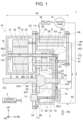
- FIG. 1 is a sectional view showing a schematic configuration of a drive apparatus 1 of an example of the present disclosure.
- the drive apparatus 1 is an integrated apparatus in which a motor, a gear unit, and an electric power conversion unit for controlling the motor are stored in a same casing.
- Directions FR, RH, UP indicate orientations of the drive apparatus 1 with respect to a vehicle when the drive apparatus 1 is mounted on a vehicle (battery electric vehicle).
- the direction FR indicates the front side in the front-rear direction of the vehicle.
- the direction RH indicates the right side in the left-right direction (or the width direction) of the vehicle.
- the direction UP indicates the upper side in the up-down direction of the vehicle.
- a plurality of axes (a motor shaft 43, a countershaft 52, and drive shafts 57L and 57R) are shown in a developed manner so as to be positioned on the same plane.
- the drive apparatus 1 is controlled by a control apparatus 2.
- the control apparatus 2 includes a CPU, a RAM, a ROM, an input-output interface, and the like.
- the control apparatus 2 is connected to the electric power conversion unit 21 and the like by a signal line (not shown).
- the drive apparatus 1 includes a casing 10.
- the casing 10 includes a first case 11, a motor case 13, and a lid portion 15.
- the first case 11 and the motor case 13 may be castings.
- the first case 11 includes a first flange 11f that extends along an outer peripheral edge of the first case 11.
- the motor case 13 includes a motor case flange 13f that extends along an outer peripheral edge of the motor case 13.
- the first case 11 is fastened to the motor case 13 by a plurality of bolts 60.
- the first case 11 includes an opening portion AP.
- the lid portion 15 is fastened to the first case 11 by the plurality of bolts 60 so as to close the opening portion AP.
- the motor case 13 includes a motor chamber 31.
- a motor 40 is stored in the motor chamber 31.
- the motor case 13 houses the motor 40.
- the motor 40 includes a stator 41, a rotor 42, and the motor shaft 43.
- the stator 41 has a cylindrical shape.
- the rotor 42 is rotatably disposed in the stator 41.
- the motor shaft 43 includes a central axis CA.
- the motor case 13 includes a facing surface 13s that faces the first case 11.
- a motor shaft hole MH and a drive shaft hole DH1 are formed in the facing surface 13s.
- the motor shaft 43 passes through the motor shaft hole MH.
- a left-side drive shaft 57L passes through the drive shaft hole DH1.
- the first case 11 includes a box-like shape of which one surface is open.
- the first case 11 is fastened to the facing surface 13s such that an opening surface is closed by the facing surface 13s.
- a gear chamber SP1 is defined between the motor case 13 and the first case 11.
- a gear unit 50 is stored in the gear chamber SP1.
- the first case 11 houses the gear unit 50.
- the gear unit 50 includes a shaft gear 51, the countershaft 52, a first counter gear 53, a second counter gear 54, a ring gear 55, and a differential gear 56.
- the shaft gear 51 is attached to the motor shaft 43.
- the first counter gear 53 and the second counter gear 54 are attached to the countershaft 52.
- the first counter gear 53 is engaged with the shaft gear 51.
- the second counter gear 54 is engaged with the ring gear 55.
- the ring gear 55 is attached to the differential gear 56.
- the pair of drive shafts 57L and 57R extend from the differential gear 56 in the vehicle width direction.
- the drive shaft 57R passes through a drive shaft hole DH2 formed in the first case 11.
- An accumulation portion 58 is included below the gear chamber SP1. Oil 61 is accumulated in the accumulation portion 58. A part of the gear unit 50 is immersed in the oil 61 accumulated in the accumulation portion 58.
- FIG. 2 shows a perspective view of the drive apparatus 1.
- a state in which the lid portion 15 and the electric power conversion unit 21 are removed is shown.
- the position of one end 43e of the motor shaft 43 is indicated by dotted lines.
- an electric unit chamber SP2 including the opening portion AP is included in the first case 11.
- the opening portion AP can be closed by fastening the lid portion 15 by the bolts 60.
- the electric unit chamber SP2 is isolated from the motor chamber 31 and the gear chamber SP1 in a liquid-tight manner.
- the electric power conversion unit 21 is stored in the electric unit chamber SP2.
- the electric power conversion unit 21 is a section for controlling generated electric power and electric power to be supplied to the motor 40.
- One example of parts included in the electric power conversion unit 21 includes an inverter, converter, and the like.
- the side on which the shaft gear 51 is disposed in the axial direction of the central axis CA of the motor shaft 43 is defined as one axial-direction side AD1.
- the opposite side is defined as the other axial-direction side AD2.
- a direction perpendicular to the central axis CA is defined as a radial direction RD.
- the drive apparatus 1 includes an oil cooling system and a water cooling system. First, the oil cooling system is described.
- the oil cooling system includes a strainer 71, an oil pump 72, an oil cooler 73, an oil passage 74, and an axial-center flow passage 75.
- oil is one example of a first heat medium
- water is one example of a second heat medium.
- the axial-center flow passage 75 is a flow passage formed on an axial line of the motor shaft 43 having a hollow shape (cylindrical shape).
- the motor shaft 43 includes the one end 43e on the one axial-direction side AD1.
- the one end 43e is positioned in the gear chamber SP1.
- An inflow port to the axial-center flow passage 75 is formed in the one end 43e.
- the one end 43e is supported by a bearing 59.
- the bearing 59 is fixed to a separating wall 11b between the gear chamber SP1 and the electric unit chamber SP2.
- the oil passage 74 is a route that supplies oil to the motor 40.
- the oil passage 74 may be various structures.
- the oil passage 74 may be a pipe member or a tunnel formed in a wall surface.
- at least a part of the oil passage 74 is configured by a pipe member.
- the oil passage 74 connects a discharge port of the oil pump 72 and an inflow port of the oil cooler 73 to each other and connects a discharge port of the oil cooler 73 and the one end 43e of the motor shaft 43 to each other.
- the oil cooler 73 is disposed in a section that connects the oil pump 72 and the one end 43e of the motor shaft 43 to each other.
- the oil accumulated in the gear chamber SP1 can be supplied to the axial-center flow passage 75 of the motor shaft 43 by the oil passage 74.
- the strainer 71 is disposed in the accumulation portion 58.
- the strainer 71 is connected to the suction port of the oil pump 72.
- the oil pump 72 is positioned on the other axial-direction side AD2 with respect to the gear chamber SP1.
- the oil pump 72 sucks the oil 61 in the accumulation portion 58 via the strainer 71.
- the oil pump 72 sends out the sucked oil to the oil cooler 73 via the oil passage 74.
- the oil cooler 73 is one example of a heat exchanger that cools the oil by exchanging heat with the coolant.
- the oil cooler 73 is positioned on the one axial-direction side AD1 with respect to the gear chamber SP1. In other words, the oil cooler 73 and the oil pump 72 face each other via the gear chamber SP1.
- the oil cooler 73 overlaps with the gear chamber SP1 in the axial direction of the central axis CA.
- the oil cooler 73 overlaps with the electric unit chamber SP2 in the radial direction RD.
- the oil passage 74 and a water passage 83 are disposed to face each other in the oil cooler 73. In other words, the oil cooler 73 is included on the oil passage 74 and the water passage 83.
- the oil passage 74 is one example of a first route.
- the water passage 83 is one example of a second route.
- the discharge port of the oil cooler 73 and the one end 43e of the motor shaft 43 are connected to each other by the oil passage 74.
- the oil passage 74 that connects the oil cooler 73 and the one end 43e to each other is positioned on the one axial-direction side AD1 with respect to the gear chamber SP1.
- a part of the electric unit chamber SP2 is positioned on an extension line of the motor shaft 43 toward the one axial-direction side AD1 (see a region A1).
- the oil passage 74 extends into the electric unit chamber SP2 from the outside of the casing 10 through a wall surface 1 1w that defines the electric unit chamber SP2 (see a region A2).
- the oil passage 74 extends through the electric unit chamber SP2 and passes through the separating wall 11b (see a region A3).
- An end portion of the oil passage 74 is connected to the axial-center flow passage 75 on the one end 43e of the motor shaft 43.
- axial-center flow passage 75 a plurality of discharge holes (not shown) that passes therethrough in the radial direction are provided.
- the oil flows through the axial-center flow passage 75 to the other axial-direction side AD2.
- the oil is caused to flow out from the discharge holes and the end portion of the axial-center flow passage 75 on the other axial-direction side AD2 to be supplied to the rotor 42, the stator 41, and the like.
- the oil supplied to the motor 40 by the axial-center flow passage 75 flows down to the lower side in the motor chamber 31.
- the oil that has flowed down returns to the accumulation portion 58 in the gear chamber SP1 via a communication hole 16 provided in a partition wall between the motor chamber 31 and the gear chamber SP1.
- the water cooling system includes a water pump 81, a radiator 82, and a water passage 83.
- the water passage 83 is a route that supplies the coolant to the electric power conversion unit 21.
- the water passage 83 is a route that circulates to the water pump 81 from the water pump 81 via the radiator 82, the electric power conversion unit 21, and the oil cooler 73.
- the oil cooler 73 overlaps with the gear chamber SP1 in the axial direction of the central axis CA.
- the oil cooler 73 can be placed within a range of the gear chamber SP1 when seen from the axial direction of the central axis CA. Therefore, a case in which at least a part of the oil cooler 73 protrudes from the casing 10 in the radial direction RD does not occur.
- the increase in the width of the drive apparatus 1 in the radial direction RD due to the oil cooler 73 can be reduced. It becomes possible to downsize the physical size of the drive apparatus 1.
- the oil cooler 73 overlaps with the electric unit chamber SP2 in the radial direction RD.
- a part of the electric unit chamber SP2 is positioned to be closer to the one axial-direction side AD1 than the oil cooler 73 by a distance DIS.
- the oil cooler 73 can be placed within a range of the electric unit chamber SP2 when seen from the radial direction RD.
- the oil cooler 73 can be housed within a range in which the electric unit chamber SP2 protrudes. Therefore, a case in which at least a part of the oil cooler 73 protrudes to the one axial-direction side AD1 from the casing 10 does not occur.
- the increase in the width of the drive apparatus 1 in the axial direction of the central axis CA due to the oil cooler 73 can be reduced. It becomes possible to downsize the physical size of the drive apparatus 1.
- the piping resistance of the oil passage 74 becomes greater as the distance from the discharge port of the oil cooler 73 to the inflow port (one end 43e) of the axial-center flow passage 75 becomes longer.
- both of the oil cooler 73 and the one end 43e are disposed on the one axial-direction side AD1 with respect to the gear chamber SP1.
- the distance from the discharge port of the oil cooler 73 to the one end 43e can be shortened as compared to a case in which the oil cooler 73 is disposed on the other axial-direction side AD2 with respect to the gear chamber SP1.
- the piping resistance of the oil passage 74 can be reduced. Therefore, it becomes possible to increase the oil flow rate while maintaining the capacity of the oil pump 72 and downsize the oil pump 72 while maintaining the oil flow rate.
- a space is formed by a dimension difference between the motor 40 and the gear unit 50 in a region on the side opposite from the gear unit 50 with respect to the motor shaft 43.
- a part of the electric unit chamber SP2 is disposed in the space.
- at least a part of the electric unit chamber SP2 overlaps with the gear chamber SP1 in the radial direction RD perpendicular to the central axis CA.
- the space around the motor shaft 43 can be effectively used. Therefore, the protruding amount of the electric unit chamber SP2 on the one axial-direction side AD1 can be reduced. It becomes possible to downsize the physical size of the drive apparatus 1.
- At least a part of the electric unit chamber SP2 overlaps with the motor chamber 31 in the axial direction of the central axis CA.
- the space around the motor shaft 43 can also be effectively used by the above. Therefore, the protruding amount of the electric unit chamber SP2 in the radial direction RD can be reduced.
- Example 2 is different from Example 1 regarding a disposing aspect of the oil pump 72. Sections in common between Example 1 and Example 2 are denoted by the same reference characters and description thereof is omitted.
- FIG. 3 shows a schematic configuration of a drive apparatus 201 of Example 2.
- FIG. 3 is a sectional view similar to FIG. 1 .
- the oil pump 72 is positioned on the one axial-direction side AD1 with respect to the gear chamber SP1. In other words, both of the oil pump 72 and the oil cooler 73 are disposed on the same direction side with respect to the gear chamber SP1.
- the oil pump 72 and the oil cooler 73 overlap with the gear chamber SP1 in the axial direction of the central axis CA.
- the oil pump 72 and the oil cooler 73 overlap with the electric unit chamber SP2 in the radial direction RD.
- the oil passage 74 connects the discharge port of the oil pump 72 and the inflow port of the oil cooler 73 to each other and connects the discharge port of the oil cooler 73 and the one end 43e of the motor shaft 43 to each other.
- Example 3 is different from Example 1 regarding a routing aspect of the oil passage 74. Sections in common between Example 1 and Example 3 are denoted by the same reference characters and description thereof is omitted.
- FIG. 4 shows a schematic configuration of a drive apparatus 301 of Example 3. FIG. 4 is a sectional view similar to FIG. 1 .
- the motor shaft 43 includes another end 43e2 on the other axial-direction side AD2.
- An inflow port to the axial-center flow passage 75 is formed in the other end 43e2.
- the oil pump 72 is positioned on the one axial-direction side AD1 with respect to the gear chamber SP1.
- both of the oil pump 72 and the oil cooler 73 are disposed on the same direction side with respect to the gear chamber SP1.
- the oil pump 72 and the oil cooler 73 overlap with the gear chamber SP1 in the axial direction of the central axis CA.
- the oil pump 72 and the oil cooler 73 overlap with the electric unit chamber SP2 in the radial direction RD.
- the oil passage 74 connects the discharge port of the oil pump 72 and the inflow port of the oil cooler 73 to each other and connects the discharge port of the oil cooler 73 and the other end 43e2 of the motor shaft 43 to each other.
- the oil flows through the axial-center flow passage 75 to the one axial-direction side AD1.
- Example 4 is different from Example 1 regarding an aspect of the casing. Sections in common between Example 1 and Example 4 are denoted by the same reference characters and description thereof is omitted.
- FIG. 5 shows a schematic configuration of a drive apparatus 401 of Example 4. FIG. 5 is a sectional view similar to FIG. 1 . In FIG. 5 , elements specific to Example 4 are distinguished by being denoted by reference characters in the 400s.
- a casing 410 includes a first case 411, a second case 412, and the motor case 13.
- the first case 411 is fastened to the facing surface 13s of the motor case 13 by the plurality of bolts 60.
- the gear chamber SP1 is defined between the motor case 13 and the first case 411.
- the second case 412 includes a box-like shape of which one surface is open.
- the second case 412 is fastened to the facing surface 13s and an upper surface 411u of the first case 411 by the plurality of bolts 60.
- the electric unit chamber SP2 is defined between the second case 412 and each of the motor case 13 and the first case 411. Therefore, a part of the electric unit chamber SP2 can be positioned on the extension line of the motor shaft 43 toward the one axial-direction side AD1 as a result of assembling the second case 412 on the first case 411 (see the region A1).
- the vehicle on which the drive apparatus of the present specification is mounted is not limited to the battery electric vehicle.
- the drive apparatus of the present specification can be mounted on a hybrid electric vehicle or a plug-in hybrid electric vehicle, for example.
- the drive apparatus of the present specification may store a planetary gear mechanism or store a plurality of motors in the casing.
- the drive apparatus of the present specification can also be applied to a vehicle that uses an electric motor in at least a part of the traveling such as a fuel cell electric vehicle, for example.
Landscapes
- Engineering & Computer Science (AREA)
- General Engineering & Computer Science (AREA)
- Power Engineering (AREA)
- Mechanical Engineering (AREA)
- Chemical & Material Sciences (AREA)
- Combustion & Propulsion (AREA)
- Transportation (AREA)
- General Details Of Gearings (AREA)
- Connection Of Motors, Electrical Generators, Mechanical Devices, And The Like (AREA)
- Motor Or Generator Cooling System (AREA)
Abstract
A drive apparatus (1) includes: a casing (10), an electric motor (40) comprising a central motor shaft (43), a gear unit (50), an electric unit (21), a first coolant route (74), a second coolant route (83) and a heat exchanger (73). The casing (10) includes a motor chamber (31), a gear chamber (SP1) and an electric unit chamber (SP2). The electric unit chamber (SP2) comprises a portion extending further to an one axial-direction side (AD1) of the motor shaft axis than the gear chamber (SP1). Said motor shaft (43) is retained at on one end (43e) in said one axial-direction side (AD1) and inside said gear chamber (SP1). The heat exchanger (73) does not extend further than said gear chamber (SP1) or said electric unit chamber (SP2) in order to enable a very compact drive apparatus (1).
Description
- The present disclosure relates to a drive apparatus.
- An integrated drive apparatus including a motor chamber, a gear chamber, and an electric unit chamber has been known. A technology of mounting an oil cooler on the integrated drive apparatus has also been known.
Japanese Unexamined Patent Application Publication No. 2020-68637 - In integrated drive apparatuses, the physical size of the drive apparatus is desired to be downsized. However, depending on an aspect of mounting an oil cooler on the drive apparatus, there is a concern that the physical size of the drive apparatus may increase due to the oil cooler.
- A drive apparatus according to a first aspect of the present disclosure includes: a casing; a motor; a gear unit; an electric unit; a first route; a second route; and a heat exchanger. The casing includes: a motor chamber; a gear chamber; and an electric unit chamber. The electric unit chamber has at least a part positioned to be closer to one axial-direction side than the gear chamber. The motor is housed in the motor chamber and includes a motor shaft. The motor shaft has one end on the one axial-direction side positioned in the gear chamber. The gear unit is housed in the gear chamber and configured to be mechanically connected to the one end of the motor shaft. The electric unit is housed in the electric unit chamber and configured to be electrically connected to the motor. The first route is configured to supply a first heat medium configured to cool the motor to the motor. The second route is configured to supply a second heat medium configured to cool the electric unit to the electric unit. The heat exchanger is included on the first route and on the second route. The heat exchanger is configured to exchange heat between the first heat medium and the second heat medium. The heat exchanger has at least a part that overlaps with the gear chamber in the axial direction and that overlaps with the electric unit chamber in a radial direction perpendicular to the axial direction.
- In the configuration described above, at least a part of the heat exchanger overlaps with the gear chamber in the axial direction of the motor shaft. As a result, the increase in the width of the drive apparatus in the axial direction due to the heat exchanger can be reduced. In the configuration described above, at least a part of the heat exchanger overlaps with the electric unit chamber in the radial direction perpendicular to the axial direction. As a result, the increase in the width of the drive apparatus in the radial direction due to the heat exchanger can be reduced. It becomes possible to downsize the physical size of the drive apparatus.
- In the drive apparatus according to the first aspect of the present disclosure, at least a part of the electric unit chamber may be positioned to be positioned on the one axial-direction side relative to the heat exchanger.
- According to the configuration described above, the increase in the width of the drive apparatus in the axial direction due to the heat exchanger can be reduced.
- In the drive apparatus according to the first aspect of the present disclosure, at least the part of the electric unit chamber may overlap with the gear chamber in the radial direction.
- According to the configuration described above, the protruding amount of the electric unit chamber to the one axial-direction side can be reduced. It becomes possible to downsize the physical size of the drive apparatus.
- In the drive apparatus according to the first aspect of the present disclosure, at least the part of the electric unit chamber may overlap with the motor chamber in the axial direction.
- According to the configuration described above, the protruding amount of the electric unit chamber in the radial direction perpendicular to the axial direction can be reduced. It becomes possible to downsize the physical size of the drive apparatus.
- In the drive apparatus according to the first aspect of the present disclosure, at least a part of the heat exchanger and at least a part of the first route may be positioned on the one axial-direction side with respect to the gear chamber.
- In the drive apparatus according to the first aspect of the present disclosure, at least the part of the first route may be configured by a pipe member.
- In the drive apparatus according to the first aspect of the present disclosure, the first route may extend into the electric unit chamber from the outside of the casing by passing through a wall surface that defines the electric unit chamber of the casing.
- According to the configuration described above, the first route that reaches one end of the motor shaft via the wall surface of the gear chamber and the inside of the electric unit chamber can be configured.
- In the drive apparatus according to the first aspect of the present disclosure, a part of the electric unit chamber may be positioned on an extension line of the motor shaft toward the one axial-direction side. The one end of the motor shaft may be supported by a separating wall between the gear chamber and the electric unit chamber. A flow passage may be provided in an axial center of the motor shaft. The first route may be configured to extend through the inside of the electric unit chamber and pass through the separating wall. The first route may be configured to be connected to the flow passage at the one end.
- According to the configuration described above, the heat medium can be supplied from the one end of the motor shaft.
- In the drive apparatus according to the first aspect of the present disclosure, the drive apparatus may further include a pump configured to send out the first heat medium accumulated in the gear chamber to the first route. The pump may be positioned on the one axial-direction side or the other axial-direction side with respect to the gear chamber. Within the first route, the heat exchanger may be disposed in a section that connects the pump and the one end of the motor shaft to each other.
- In the drive apparatus according to the first aspect of the present disclosure, the motor chamber and the gear chamber may be connected to each other by a communication hole configured such that the first heat medium flows through the communication hole. The electric unit chamber may be isolated from the motor chamber and the gear chamber in a liquid-tight manner.
- In the drive apparatus according to the first aspect of the present disclosure, the casing may include: a motor case including the motor chamber; a gear case configured to define at least a part of the gear chamber; and an electric unit case configured to define at least a part of the electric unit chamber. The gear case and the electric unit case may be fastened to the motor case by a plurality of fastening members.
- According to the configuration described above, the gear case and the electric unit case can be assembled independently of each other. The ease of constructing the drive apparatus can be enhanced.
- Features, advantages, and technical and industrial significance of exemplary embodiments of the invention will be described below with reference to the accompanying drawings, in which like signs denote like elements, and wherein:
-
FIG. 1 is a sectional view showing a schematic configuration of a drive apparatus; -
FIG. 2 is a perspective view of the drive apparatus; -
FIG. 3 is a sectional view showing a schematic configuration of the drive apparatus; -
FIG. 4 is a sectional view showing a schematic configuration of the drive apparatus; and -
FIG. 5 is a sectional view showing a schematic configuration of the drive apparatus. -
FIG. 1 is a sectional view showing a schematic configuration of adrive apparatus 1 of an example of the present disclosure. Thedrive apparatus 1 is an integrated apparatus in which a motor, a gear unit, and an electric power conversion unit for controlling the motor are stored in a same casing. Directions FR, RH, UP indicate orientations of thedrive apparatus 1 with respect to a vehicle when thedrive apparatus 1 is mounted on a vehicle (battery electric vehicle). The direction FR indicates the front side in the front-rear direction of the vehicle. The direction RH indicates the right side in the left-right direction (or the width direction) of the vehicle. The direction UP indicates the upper side in the up-down direction of the vehicle. The same applies to other drawings. InFIG. 1 , a plurality of axes (amotor shaft 43, acountershaft 52, and driveshafts - The
drive apparatus 1 is controlled by acontrol apparatus 2. Thecontrol apparatus 2 includes a CPU, a RAM, a ROM, an input-output interface, and the like. Thecontrol apparatus 2 is connected to the electricpower conversion unit 21 and the like by a signal line (not shown). - The
drive apparatus 1 includes acasing 10. Thecasing 10 includes afirst case 11, amotor case 13, and alid portion 15. Thefirst case 11 and themotor case 13 may be castings. - The
first case 11 includes afirst flange 11f that extends along an outer peripheral edge of thefirst case 11. Themotor case 13 includes amotor case flange 13f that extends along an outer peripheral edge of themotor case 13. Thefirst case 11 is fastened to themotor case 13 by a plurality ofbolts 60. Thefirst case 11 includes an opening portion AP. Thelid portion 15 is fastened to thefirst case 11 by the plurality ofbolts 60 so as to close the opening portion AP. - The
motor case 13 includes amotor chamber 31. Amotor 40 is stored in themotor chamber 31. In other words, themotor case 13 houses themotor 40. Themotor 40 includes astator 41, arotor 42, and themotor shaft 43. Thestator 41 has a cylindrical shape. Therotor 42 is rotatably disposed in thestator 41. Themotor shaft 43 includes a central axis CA. - The
motor case 13 includes a facingsurface 13s that faces thefirst case 11. A motor shaft hole MH and a drive shaft hole DH1 are formed in the facingsurface 13s. Themotor shaft 43 passes through the motor shaft hole MH. A left-side drive shaft 57L passes through the drive shaft hole DH1. - The
first case 11 includes a box-like shape of which one surface is open. Thefirst case 11 is fastened to the facingsurface 13s such that an opening surface is closed by the facingsurface 13s. As a result, a gear chamber SP1 is defined between themotor case 13 and thefirst case 11. Agear unit 50 is stored in the gear chamber SP1. In other words, thefirst case 11 houses thegear unit 50. - The
gear unit 50 includes ashaft gear 51, thecountershaft 52, afirst counter gear 53, asecond counter gear 54, aring gear 55, and adifferential gear 56. Theshaft gear 51 is attached to themotor shaft 43. As a result, thegear unit 50 and themotor 40 are mechanically connected to each other. Thefirst counter gear 53 and thesecond counter gear 54 are attached to thecountershaft 52. Thefirst counter gear 53 is engaged with theshaft gear 51. Thesecond counter gear 54 is engaged with thering gear 55. Thering gear 55 is attached to thedifferential gear 56. The pair ofdrive shafts differential gear 56 in the vehicle width direction. Thedrive shaft 57R passes through a drive shaft hole DH2 formed in thefirst case 11. Anaccumulation portion 58 is included below the gear chamber SP1.Oil 61 is accumulated in theaccumulation portion 58. A part of thegear unit 50 is immersed in theoil 61 accumulated in theaccumulation portion 58. -
FIG. 2 shows a perspective view of thedrive apparatus 1. InFIG. 2 , a state in which thelid portion 15 and the electricpower conversion unit 21 are removed is shown. The position of oneend 43e of themotor shaft 43 is indicated by dotted lines. As shown inFIG. 1 andFIG. 2 , an electric unit chamber SP2 including the opening portion AP is included in thefirst case 11. The opening portion AP can be closed by fastening thelid portion 15 by thebolts 60. In other words, the electric unit chamber SP2 is isolated from themotor chamber 31 and the gear chamber SP1 in a liquid-tight manner. The electricpower conversion unit 21 is stored in the electric unit chamber SP2. The electricpower conversion unit 21 is a section for controlling generated electric power and electric power to be supplied to themotor 40. One example of parts included in the electricpower conversion unit 21 includes an inverter, converter, and the like. - The side on which the
shaft gear 51 is disposed in the axial direction of the central axis CA of themotor shaft 43 is defined as one axial-direction side AD1. The opposite side is defined as the other axial-direction side AD2. A direction perpendicular to the central axis CA is defined as a radial direction RD. - The
drive apparatus 1 includes an oil cooling system and a water cooling system. First, the oil cooling system is described. The oil cooling system includes astrainer 71, anoil pump 72, anoil cooler 73, anoil passage 74, and an axial-center flow passage 75. In other words, in the present embodiment, oil is one example of a first heat medium, and water is one example of a second heat medium. - The axial-
center flow passage 75 is a flow passage formed on an axial line of themotor shaft 43 having a hollow shape (cylindrical shape). Themotor shaft 43 includes the oneend 43e on the one axial-direction side AD1. The oneend 43e is positioned in the gear chamber SP1. An inflow port to the axial-center flow passage 75 is formed in the oneend 43e. The oneend 43e is supported by abearing 59. Thebearing 59 is fixed to a separatingwall 11b between the gear chamber SP1 and the electric unit chamber SP2. - The
oil passage 74 is a route that supplies oil to themotor 40. Theoil passage 74 may be various structures. For example, theoil passage 74 may be a pipe member or a tunnel formed in a wall surface. In the present example, at least a part of theoil passage 74 is configured by a pipe member. - The
oil passage 74 connects a discharge port of theoil pump 72 and an inflow port of theoil cooler 73 to each other and connects a discharge port of theoil cooler 73 and the oneend 43e of themotor shaft 43 to each other. In other words, within theoil passage 74, theoil cooler 73 is disposed in a section that connects theoil pump 72 and the oneend 43e of themotor shaft 43 to each other. The oil accumulated in the gear chamber SP1 can be supplied to the axial-center flow passage 75 of themotor shaft 43 by theoil passage 74. - The
strainer 71 is disposed in theaccumulation portion 58. Thestrainer 71 is connected to the suction port of theoil pump 72. Theoil pump 72 is positioned on the other axial-direction side AD2 with respect to the gear chamber SP1. Theoil pump 72 sucks theoil 61 in theaccumulation portion 58 via thestrainer 71. Then, theoil pump 72 sends out the sucked oil to theoil cooler 73 via theoil passage 74. - The
oil cooler 73 is one example of a heat exchanger that cools the oil by exchanging heat with the coolant. Theoil cooler 73 is positioned on the one axial-direction side AD1 with respect to the gear chamber SP1. In other words, theoil cooler 73 and theoil pump 72 face each other via the gear chamber SP1. Theoil cooler 73 overlaps with the gear chamber SP1 in the axial direction of the central axis CA. Theoil cooler 73 overlaps with the electric unit chamber SP2 in the radial direction RD. Theoil passage 74 and awater passage 83 are disposed to face each other in theoil cooler 73. In other words, theoil cooler 73 is included on theoil passage 74 and thewater passage 83. In the present embodiment, theoil passage 74 is one example of a first route. Thewater passage 83 is one example of a second route. - The discharge port of the
oil cooler 73 and the oneend 43e of themotor shaft 43 are connected to each other by theoil passage 74. Theoil passage 74 that connects theoil cooler 73 and the oneend 43e to each other is positioned on the one axial-direction side AD1 with respect to the gear chamber SP1. Specifically, a part of the electric unit chamber SP2 is positioned on an extension line of themotor shaft 43 toward the one axial-direction side AD1 (see a region A1). Theoil passage 74 extends into the electric unit chamber SP2 from the outside of thecasing 10 through awall surface 1 1w that defines the electric unit chamber SP2 (see a region A2). Theoil passage 74 extends through the electric unit chamber SP2 and passes through the separatingwall 11b (see a region A3). An end portion of theoil passage 74 is connected to the axial-center flow passage 75 on the oneend 43e of themotor shaft 43. - In the axial-
center flow passage 75, a plurality of discharge holes (not shown) that passes therethrough in the radial direction are provided. The oil flows through the axial-center flow passage 75 to the other axial-direction side AD2. The oil is caused to flow out from the discharge holes and the end portion of the axial-center flow passage 75 on the other axial-direction side AD2 to be supplied to therotor 42, thestator 41, and the like. The oil supplied to themotor 40 by the axial-center flow passage 75 flows down to the lower side in themotor chamber 31. The oil that has flowed down returns to theaccumulation portion 58 in the gear chamber SP1 via acommunication hole 16 provided in a partition wall between themotor chamber 31 and the gear chamber SP1. - Next, the water cooling system is described. The water cooling system includes a
water pump 81, aradiator 82, and awater passage 83. Thewater passage 83 is a route that supplies the coolant to the electricpower conversion unit 21. Thewater passage 83 is a route that circulates to thewater pump 81 from thewater pump 81 via theradiator 82, the electricpower conversion unit 21, and theoil cooler 73. By the coolant that circulates through thewater passage 83, the electricpower conversion unit 21 can be cooled, and the oil can be cooled in theoil cooler 73. - In the
drive apparatus 1 of the present example, theoil cooler 73 overlaps with the gear chamber SP1 in the axial direction of the central axis CA. As a result, theoil cooler 73 can be placed within a range of the gear chamber SP1 when seen from the axial direction of the central axis CA. Therefore, a case in which at least a part of theoil cooler 73 protrudes from thecasing 10 in the radial direction RD does not occur. As a result, the increase in the width of thedrive apparatus 1 in the radial direction RD due to theoil cooler 73 can be reduced. It becomes possible to downsize the physical size of thedrive apparatus 1. - In the
drive apparatus 1 of the present example, theoil cooler 73 overlaps with the electric unit chamber SP2 in the radial direction RD. A part of the electric unit chamber SP2 is positioned to be closer to the one axial-direction side AD1 than theoil cooler 73 by a distance DIS. As a result, theoil cooler 73 can be placed within a range of the electric unit chamber SP2 when seen from the radial direction RD. In other words, theoil cooler 73 can be housed within a range in which the electric unit chamber SP2 protrudes. Therefore, a case in which at least a part of theoil cooler 73 protrudes to the one axial-direction side AD1 from thecasing 10 does not occur. As a result, the increase in the width of thedrive apparatus 1 in the axial direction of the central axis CA due to theoil cooler 73 can be reduced. It becomes possible to downsize the physical size of thedrive apparatus 1. - The piping resistance of the
oil passage 74 becomes greater as the distance from the discharge port of theoil cooler 73 to the inflow port (oneend 43e) of the axial-center flow passage 75 becomes longer. Thus, in the technology of the present example, both of theoil cooler 73 and the oneend 43e are disposed on the one axial-direction side AD1 with respect to the gear chamber SP1. As a result, the distance from the discharge port of theoil cooler 73 to the oneend 43e can be shortened as compared to a case in which theoil cooler 73 is disposed on the other axial-direction side AD2 with respect to the gear chamber SP1. The piping resistance of theoil passage 74 can be reduced. Therefore, it becomes possible to increase the oil flow rate while maintaining the capacity of theoil pump 72 and downsize theoil pump 72 while maintaining the oil flow rate. - As shown in
FIG. 1 , a space is formed by a dimension difference between themotor 40 and thegear unit 50 in a region on the side opposite from thegear unit 50 with respect to themotor shaft 43. A part of the electric unit chamber SP2 is disposed in the space. In other words, at least a part of the electric unit chamber SP2 overlaps with the gear chamber SP1 in the radial direction RD perpendicular to the central axis CA. As a result, the space around themotor shaft 43 can be effectively used. Therefore, the protruding amount of the electric unit chamber SP2 on the one axial-direction side AD1 can be reduced. It becomes possible to downsize the physical size of thedrive apparatus 1. - At least a part of the electric unit chamber SP2 overlaps with the
motor chamber 31 in the axial direction of the central axis CA. The space around themotor shaft 43 can also be effectively used by the above. Therefore, the protruding amount of the electric unit chamber SP2 in the radial direction RD can be reduced. - Example 2 is different from Example 1 regarding a disposing aspect of the
oil pump 72. Sections in common between Example 1 and Example 2 are denoted by the same reference characters and description thereof is omitted. -
FIG. 3 shows a schematic configuration of adrive apparatus 201 of Example 2.FIG. 3 is a sectional view similar toFIG. 1 . Theoil pump 72 is positioned on the one axial-direction side AD1 with respect to the gear chamber SP1. In other words, both of theoil pump 72 and theoil cooler 73 are disposed on the same direction side with respect to the gear chamber SP1. Theoil pump 72 and theoil cooler 73 overlap with the gear chamber SP1 in the axial direction of the central axis CA. Theoil pump 72 and theoil cooler 73 overlap with the electric unit chamber SP2 in the radial direction RD. Theoil passage 74 connects the discharge port of theoil pump 72 and the inflow port of theoil cooler 73 to each other and connects the discharge port of theoil cooler 73 and the oneend 43e of themotor shaft 43 to each other. - A case in which at least a part of the
oil cooler 73 protrudes from thecasing 10 in the radial direction RD or to the one axial-direction side AD1 does not occur in thedrive apparatus 201 of Example 2 as well. It becomes possible to reduce the increase in the physical size of thedrive apparatus 1 due to theoil cooler 73. - Example 3 is different from Example 1 regarding a routing aspect of the
oil passage 74. Sections in common between Example 1 and Example 3 are denoted by the same reference characters and description thereof is omitted.FIG. 4 shows a schematic configuration of adrive apparatus 301 of Example 3.FIG. 4 is a sectional view similar toFIG. 1 . - In the
drive apparatus 301 of Example 3, themotor shaft 43 includes another end 43e2 on the other axial-direction side AD2. An inflow port to the axial-center flow passage 75 is formed in the other end 43e2. Theoil pump 72 is positioned on the one axial-direction side AD1 with respect to the gear chamber SP1. In other words, both of theoil pump 72 and theoil cooler 73 are disposed on the same direction side with respect to the gear chamber SP1. Theoil pump 72 and theoil cooler 73 overlap with the gear chamber SP1 in the axial direction of the central axis CA. Theoil pump 72 and theoil cooler 73 overlap with the electric unit chamber SP2 in the radial direction RD. Theoil passage 74 connects the discharge port of theoil pump 72 and the inflow port of theoil cooler 73 to each other and connects the discharge port of theoil cooler 73 and the other end 43e2 of themotor shaft 43 to each other. The oil flows through the axial-center flow passage 75 to the one axial-direction side AD1. - It becomes possible to reduce the increase in the physical size of the
drive apparatus 301 due to theoil cooler 73 in thedrive apparatus 301 of Example 3 as well. - Example 4 is different from Example 1 regarding an aspect of the casing. Sections in common between Example 1 and Example 4 are denoted by the same reference characters and description thereof is omitted.
FIG. 5 shows a schematic configuration of adrive apparatus 401 of Example 4.FIG. 5 is a sectional view similar toFIG. 1 . InFIG. 5 , elements specific to Example 4 are distinguished by being denoted by reference characters in the 400s. - A
casing 410 includes afirst case 411, asecond case 412, and themotor case 13. Thefirst case 411 is fastened to the facingsurface 13s of themotor case 13 by the plurality ofbolts 60. The gear chamber SP1 is defined between themotor case 13 and thefirst case 411. - The
second case 412 includes a box-like shape of which one surface is open. Thesecond case 412 is fastened to the facingsurface 13s and anupper surface 411u of thefirst case 411 by the plurality ofbolts 60. As a result, the electric unit chamber SP2 is defined between thesecond case 412 and each of themotor case 13 and thefirst case 411. Therefore, a part of the electric unit chamber SP2 can be positioned on the extension line of themotor shaft 43 toward the one axial-direction side AD1 as a result of assembling thesecond case 412 on the first case 411 (see the region A1). - It becomes possible to attach the electric
power conversion unit 21 in a state in which only thesecond case 412 is removed from themotor case 13 by separately configuring thefirst case 411 that houses thegear unit 50 and thesecond case 412 that houses the electricpower conversion unit 21. As a result, there are no interferences from thesecond case 412 when the electricpower conversion unit 21 is attached. Therefore, the direction of access of a tool to a contact portion between the electricpower conversion unit 21 and the facingsurface 13s can be enlarged (see a dotted arrow Y1). The ease of assembly of the electricpower conversion unit 21 can be enhanced. - The embodiments have been described in detail above, but those are merely exemplifications and do not limit the scope of claims. The technology described in the scope of claims includes those obtained by variously modifying and changing the specific examples exemplified above. The technical elements described in the present specification or the drawings exhibit a technical utility by itself or various combinations, and are not limited to the combinations described in the claims as originally filed. The technology exemplified in the present specification or the drawings achieves a plurality of objects at the same time, and has a technical utility as a result of achievement of one of those objects itself.
- The vehicle on which the drive apparatus of the present specification is mounted is not limited to the battery electric vehicle. The drive apparatus of the present specification can be mounted on a hybrid electric vehicle or a plug-in hybrid electric vehicle, for example. In this case, the drive apparatus of the present specification may store a planetary gear mechanism or store a plurality of motors in the casing. The drive apparatus of the present specification can also be applied to a vehicle that uses an electric motor in at least a part of the traveling such as a fuel cell electric vehicle, for example.
Claims (11)
- A drive apparatus (1; 201; 301; 401), comprising:a casing (10;410) including:a motor chamber (31);a gear chamber (SP1); andan electric unit chamber (SP2), the electric unit chamber (SP2) having at least a part positioned to be closer to one axial-direction side than the gear chamber (SP1);a motor (40) housed in the motor chamber (31) and including a motor shaft (43), the motor shaft (43) having one end on the one axial-direction side positioned in the gear chamber (SP1);a gear unit (50) housed in the gear chamber (SP1) and configured to be mechanically connected to the one end of the motor shaft (43);an electric unit (21) housed in the electric unit chamber (SP2) and configured to be electrically connected to the motor (40);a first route (74) configured to supply a first heat medium configured to cool the motor (40) to the motor (40);a second route (83) configured to supply a second heat medium configured to cool the electric unit (21) to the electric unit (21); anda heat exchanger (73) configured to:be included on the first route (74) and on the second route (83);exchange heat between the first heat medium and the second heat medium; andhave at least a part that overlaps with the gear chamber (SP1) in the axial direction and that overlaps with the electric unit chamber (SP2) in a radial direction perpendicular to the axial direction.
- The drive apparatus (1; 201; 301; 401) according to claim 1, wherein at least a part of the electric unit chamber (SP2) is positioned to be positioned on the one axial-direction side relative to the heat exchanger (73).
- The drive apparatus (1; 201; 301; 401) according to claim 2, wherein at least the part of the electric unit chamber (SP2) overlaps with the gear chamber (SP1) in the radial direction.
- The drive apparatus (1; 201; 301; 401) according to claim 3, wherein at least the part of the electric unit chamber (SP2) overlaps with the motor chamber (31) in the axial direction.
- The drive apparatus (1; 201; 301; 401) according to claim 1, wherein at least a part of the heat exchanger (73) and at least a part of the first route (74) are positioned on the one axial-direction side with respect to the gear chamber (SP1).
- The drive apparatus (1; 201; 301; 401) according to claim 5, wherein at least the part of the first route (74) is configured by a pipe member.
- The drive apparatus (1; 201; 301; 401) according to claim 5, wherein the first route (74) extends into the electric unit chamber (SP2) from an outside of the casing (10;410) by passing through a wall surface that defines the electric unit chamber (SP2) of the casing (10;410).
- The drive apparatus (1; 201; 301; 401) according to claim 7, wherein:a part of the electric unit chamber (SP2) is positioned on an extension line of the motor shaft (43) toward the one axial-direction side;the one end of the motor shaft (43) is supported by a separating wall between the gear chamber (SP1) and the electric unit chamber (SP2);a flow passage (75) is provided in an axial center of the motor shaft (43);the first route (74) is configured to extend through an inside of the electric unit chamber (SP2) and pass through the separating wall; andthe first route (74) is configured to be connected to the flow passage at the one end.
- The drive apparatus (1; 201; 301; 401) according to claim 8, further comprising a pump (72) configured to send out the first heat medium accumulated in the gear chamber (SP1) to the first route (74), wherein:the pump (72) is positioned on the one axial-direction side or the other axial-direction side with respect to the gear chamber (SP1); andwithin the first route (74), the heat exchanger (73) is disposed in a section that connects the pump (72) and the one end of the motor shaft (43) to each other.
- The drive apparatus (1; 201; 301; 401) according to claim 1, wherein:the motor chamber (31) and the gear chamber (SP1) are connected to each other by a communication hole configured such that the first heat medium flows through the communication hole; andthe electric unit chamber (SP2) is isolated from the motor chamber (31) and the gear chamber (SP1) in a liquid-tight manner.
- The drive apparatus (1; 201; 301; 401) according to claim 1, wherein:the casing (10;410) includes:a motor case including the motor chamber (31);a gear case configured to define at least a part of the gear chamber (SP1); andan electric unit case configured to define at least a part of the electric unit chamber (SP2); andthe gear case and the electric unit case are fastened to the motor case by a plurality of fastening members.
Applications Claiming Priority (1)
| Application Number | Priority Date | Filing Date | Title |
|---|---|---|---|
| JP2023180984A JP2025070560A (en) | 2023-10-20 | 2023-10-20 | Drive unit |
Publications (1)
| Publication Number | Publication Date |
|---|---|
| EP4542830A1 true EP4542830A1 (en) | 2025-04-23 |
Family
ID=93061579
Family Applications (1)
| Application Number | Title | Priority Date | Filing Date |
|---|---|---|---|
| EP24205598.6A Pending EP4542830A1 (en) | 2023-10-20 | 2024-10-09 | Drive apparatus |
Country Status (5)
| Country | Link |
|---|---|
| US (1) | US20250132631A1 (en) |
| EP (1) | EP4542830A1 (en) |
| JP (1) | JP2025070560A (en) |
| KR (1) | KR20250057636A (en) |
| CN (1) | CN119865003A (en) |
Families Citing this family (1)
| Publication number | Priority date | Publication date | Assignee | Title |
|---|---|---|---|---|
| JP2025070559A (en) * | 2023-10-20 | 2025-05-02 | トヨタ自動車株式会社 | Drive unit |
Citations (5)
| Publication number | Priority date | Publication date | Assignee | Title |
|---|---|---|---|---|
| JP2020068637A (en) | 2018-10-26 | 2020-04-30 | 日本電産株式会社 | Cooling system |
| DE102020104186A1 (en) * | 2019-03-22 | 2020-09-24 | Nidec Corporation | DRIVE DEVICE AND OIL CHANGE PROCEDURE |
| DE112020006745T5 (en) * | 2020-02-19 | 2022-12-22 | Nidec Corporation | ENGINE UNIT |
| DE102022208717A1 (en) * | 2021-08-24 | 2023-03-02 | Nidec Corporation | drive device |
| EP4254744A1 (en) * | 2021-03-31 | 2023-10-04 | BYD Company Limited | Motor system and vehicle having same |
Family Cites Families (2)
| Publication number | Priority date | Publication date | Assignee | Title |
|---|---|---|---|---|
| WO2022270211A1 (en) * | 2021-06-24 | 2022-12-29 | ジヤトコ株式会社 | Unit |
| CN113691192B (en) * | 2021-07-07 | 2024-09-17 | 华为数字能源技术有限公司 | A powertrain, coolant flow estimation method and electric vehicle |
-
2023
- 2023-10-20 JP JP2023180984A patent/JP2025070560A/en active Pending
-
2024
- 2024-10-07 KR KR1020240135509A patent/KR20250057636A/en active Pending
- 2024-10-08 US US18/909,054 patent/US20250132631A1/en active Granted
- 2024-10-09 EP EP24205598.6A patent/EP4542830A1/en active Pending
- 2024-10-10 CN CN202411405293.1A patent/CN119865003A/en active Pending
Patent Citations (5)
| Publication number | Priority date | Publication date | Assignee | Title |
|---|---|---|---|---|
| JP2020068637A (en) | 2018-10-26 | 2020-04-30 | 日本電産株式会社 | Cooling system |
| DE102020104186A1 (en) * | 2019-03-22 | 2020-09-24 | Nidec Corporation | DRIVE DEVICE AND OIL CHANGE PROCEDURE |
| DE112020006745T5 (en) * | 2020-02-19 | 2022-12-22 | Nidec Corporation | ENGINE UNIT |
| EP4254744A1 (en) * | 2021-03-31 | 2023-10-04 | BYD Company Limited | Motor system and vehicle having same |
| DE102022208717A1 (en) * | 2021-08-24 | 2023-03-02 | Nidec Corporation | drive device |
Also Published As
| Publication number | Publication date |
|---|---|
| JP2025070560A (en) | 2025-05-02 |
| CN119865003A (en) | 2025-04-22 |
| US20250132631A1 (en) | 2025-04-24 |
| KR20250057636A (en) | 2025-04-29 |
Similar Documents
| Publication | Publication Date | Title |
|---|---|---|
| JP7613542B2 (en) | Motor Unit | |
| CN114901499B (en) | Driving device | |
| CN111817499B (en) | Drive device | |
| CN115133721B (en) | Drive device | |
| CN113193679B (en) | Motor unit | |
| US12132352B2 (en) | Stator cooling structure | |
| EP4542830A1 (en) | Drive apparatus | |
| CN109565226B (en) | drive | |
| JP2000303949A (en) | Hydraulic pump with built-in motor | |
| EP4484195A1 (en) | Cooling module | |
| EP4495399B1 (en) | Cooling module | |
| CN113678303A (en) | Cooling device and housing | |
| CN112787456B (en) | Vehicle, motor and shell structure | |
| EP4546618A1 (en) | Drive device | |
| JP7447623B2 (en) | motor unit | |
| EP4583376A1 (en) | Motor unit | |
| EP4583377A1 (en) | Motor unit | |
| US12549060B2 (en) | Coolant flow passage structure in rotating machine | |
| EP4575271A1 (en) | Vehicle drive device | |
| JP2025117306A (en) | Motor | |
| JPH10336967A (en) | Composite machine comprising prime mover, generator and pump unit | |
| WO2024142456A1 (en) | Drive device | |
| CN116733949A (en) | Oil cooler | |
| CN118269539A (en) | Thermal management water side integrated box, thermal management system and automobile | |
| WO2024004436A1 (en) | Drive device |
Legal Events
| Date | Code | Title | Description |
|---|---|---|---|
| PUAI | Public reference made under article 153(3) epc to a published international application that has entered the european phase |
Free format text: ORIGINAL CODE: 0009012 |
|
| STAA | Information on the status of an ep patent application or granted ep patent |
Free format text: STATUS: REQUEST FOR EXAMINATION WAS MADE |
|
| 17P | Request for examination filed |
Effective date: 20241025 |
|
| AK | Designated contracting states |
Kind code of ref document: A1 Designated state(s): AL AT BE BG CH CY CZ DE DK EE ES FI FR GB GR HR HU IE IS IT LI LT LU LV MC ME MK MT NL NO PL PT RO RS SE SI SK SM TR |