EP4542803A1 - Method, device and system for determining a fault in a double-circuit line - Google Patents

Method, device and system for determining a fault in a double-circuit line Download PDF

Info

Publication number
EP4542803A1
EP4542803A1 EP23204584.9A EP23204584A EP4542803A1 EP 4542803 A1 EP4542803 A1 EP 4542803A1 EP 23204584 A EP23204584 A EP 23204584A EP 4542803 A1 EP4542803 A1 EP 4542803A1
Authority
EP
European Patent Office
Prior art keywords
line
fault
angle
monitored
power
Prior art date
Legal status (The legal status is an assumption and is not a legal conclusion. Google has not performed a legal analysis and makes no representation as to the accuracy of the status listed.)
Pending
Application number
EP23204584.9A
Other languages
German (de)
French (fr)
Inventor
Obbalareddi Demudu NAIDU
Neethu GEORGE
Current Assignee (The listed assignees may be inaccurate. Google has not performed a legal analysis and makes no representation or warranty as to the accuracy of the list.)
Hitachi Energy Ltd
Original Assignee
Hitachi Energy Ltd
Priority date (The priority date is an assumption and is not a legal conclusion. Google has not performed a legal analysis and makes no representation as to the accuracy of the date listed.)
Filing date
Publication date
Application filed by Hitachi Energy Ltd filed Critical Hitachi Energy Ltd
Priority to EP23204584.9A priority Critical patent/EP4542803A1/en
Priority to PCT/EP2024/077162 priority patent/WO2025082720A1/en
Publication of EP4542803A1 publication Critical patent/EP4542803A1/en
Pending legal-status Critical Current

Links

Images

Classifications

    • HELECTRICITY
    • H02GENERATION; CONVERSION OR DISTRIBUTION OF ELECTRIC POWER
    • H02HEMERGENCY PROTECTIVE CIRCUIT ARRANGEMENTS
    • H02H3/00Emergency protective circuit arrangements for automatic disconnection directly responsive to an undesired change from normal electric working condition with or without subsequent reconnection ; integrated protection
    • H02H3/42Emergency protective circuit arrangements for automatic disconnection directly responsive to an undesired change from normal electric working condition with or without subsequent reconnection ; integrated protection responsive to product of voltage and current
    • H02H3/425Emergency protective circuit arrangements for automatic disconnection directly responsive to an undesired change from normal electric working condition with or without subsequent reconnection ; integrated protection responsive to product of voltage and current using phase sequence analysing arrangements
    • GPHYSICS
    • G01MEASURING; TESTING
    • G01RMEASURING ELECTRIC VARIABLES; MEASURING MAGNETIC VARIABLES
    • G01R31/00Arrangements for testing electric properties; Arrangements for locating electric faults; Arrangements for electrical testing characterised by what is being tested not provided for elsewhere
    • G01R31/08Locating faults in cables, transmission lines, or networks
    • GPHYSICS
    • G01MEASURING; TESTING
    • G01RMEASURING ELECTRIC VARIABLES; MEASURING MAGNETIC VARIABLES
    • G01R31/00Arrangements for testing electric properties; Arrangements for locating electric faults; Arrangements for electrical testing characterised by what is being tested not provided for elsewhere
    • G01R31/08Locating faults in cables, transmission lines, or networks
    • G01R31/081Locating faults in cables, transmission lines, or networks according to type of conductors
    • G01R31/085Locating faults in cables, transmission lines, or networks according to type of conductors in power transmission or distribution lines, e.g. overhead
    • HELECTRICITY
    • H02GENERATION; CONVERSION OR DISTRIBUTION OF ELECTRIC POWER
    • H02HEMERGENCY PROTECTIVE CIRCUIT ARRANGEMENTS
    • H02H7/00Emergency protective circuit arrangements specially adapted for specific types of electric machines or apparatus or for sectionalised protection of cable or line systems, and effecting automatic switching in the event of an undesired change from normal working conditions
    • H02H7/26Sectionalised protection of cable or line systems, e.g. for disconnecting a section on which a short-circuit, earth fault, or arc discharge has occured
    • H02H7/267Sectionalised protection of cable or line systems, e.g. for disconnecting a section on which a short-circuit, earth fault, or arc discharge has occured for parallel lines and wires

Definitions

  • the present disclosure relates to a method, device and system for determining a fault in a double-circuit line.
  • the present disclosure relates to secure distance protection and accurate fault location for double-circuit lines connected to conventional and/or renewable energy sources.
  • Double-circuit lines are widely used on transmission systems due to their significant efficiency, reliability, economic and environmental advantages over single-circuit lines. For example, currently, more than 50% of the transmission line circuit length in India is constituted of 400 kV and 765 kV lines [1], of which a majority are double circuit lines. However, due to the mutual coupling effects between the two circuits, the transient signals induced on the two circuits due to a fault on one circuit are quite different from those encountered on a single-circuit line. This makes the protection of these lines more complicated.
  • Figs. 1 and 2 show exemplary double-circuit line system configurations and the particular problems associated therewith.
  • the stepped arrows downwards each indicate the location of the fault, V x and I x denote voltages and currents, respectively.
  • Figs. 1 and 2 show a double-circuit line which connects an inverter-based renewable (IBR) to the grid.
  • Fig. 1A and 1B indicate two fault scenarios.
  • the current on line 2 flows out of the IBR into the fault through the remote end.
  • the current IL1 seen by relay R is purely controlled in nature.
  • the traditional phasor-based distance element [11] will malfunction, whereas distance protection methods proposed for IBR-connected lines in recent literature [9], [10] will work reliably.
  • a second fault scenario as seen in Fig. 1B .
  • the current on line 2 is such that the current from the strong remote grid feeds into the fault through the local end.
  • the current IL1 seen by relay R consists of a significant component from the stronger remote grid. It is not as controlled in nature as in the case of first fault scenario.
  • the traditional distance element [11] works reliably, whereas new distance protection methods proposed for relays seeing controlled IBR currents will see limitations.
  • Fig. 2 shows a double-circuit line with a generation mix of IBR and a strong synchronous generator-based grid at both ends.
  • the nature of the current IL 1 seen by relay R depends on the penetration of the IBR at the local end at the time of fault. This in turn can depend on the time of day, weather, and many other environmental and technical factors.
  • the current IL 1 seen by relay R can be controlled or non-controlled in nature. This again creates a scenario, where, depending on various environmental and technical factors, the nature of the relay current varies, and the performance of traditional and proposed distance protection methods [9], [10] varies.
  • the recently proposed modified distance protection methods [9], [10] are not reliable. This is because they are based on the assumption that the remote end is connected to traditional generators only and has no penetration of IBR.
  • the invention proposes a generic, single-ended, local measurement-based method for protection and fault location on double-circuit lines connected to IBRs at either or both ends.
  • the method may rely on local voltage measurement and current measurements from both lines as an input (which can be sampled values obtained through process bus at digital substations based on IEC 61850).
  • the method also incorporates the effect of mutual coupling in double-circuit lines.
  • the disclosure also relates to a corresponding device and system.
  • the disclosure provides a generic, single-ended, local measurement-based method for protection of double-circuit lines connected to IBRs at either or both ends or conventional sources.
  • the disclosure considers the impact of mutual coupling effects in double-circuit lines which can potentially cause underreach or overreach in existing distance protection methods [11].
  • the proposed method is very minimally impacted by the magnitude of fault resistance. It provides much better fault resistance coverage when compared to existing and proposed distance protection methods.
  • the present disclosure relates to a method for determining a fault in a double-circuit line comprising a first line and a second line.
  • the method comprises calculating a first angle of a power at a beginning of a monitored line length of the first line, calculating a second angle of a power at an end of the monitored line length of the first line, performing an operation with the first angle and the second angle to calculate a first fault factor, and determining whether the fault is on the first or second line based on a polarity of the first fault factor.
  • the operation is a multiplication, a division, a logical operation or performed using a truth table.
  • the fault is determined to be on the first line in case the first fault factor is of a first polarity, and the fault is determined to be on the second line in case the sign of the first fault factor is of a second polarity.
  • the polarity comprises a sign of the first fault factor.
  • the method further comprises acquiring local voltage and current measurements of the first and second line, wherein the calculation of the first angle and the second angle are performed using the local voltage and current measurements of the first and second line.
  • the method further comprises calculating a fault angle over the complete monitored line length of the line having the fault, wherein the location of the fault is determined based on a zero crossing of the fault angle.
  • the method further comprises acquiring local voltage and current measurements of the first and second line, calculating a first bus voltage at the end of the monitored line length of the first line based on the local voltage and current measurements of the first line, calculating a second bus voltage at an end of a monitored line length of the second line based on the local voltage and current measurements of the second line and determining whether the fault is inside or outside of the monitored line length based on the first and second bus voltage.
  • the fault is determined to be outside of the monitored line length in case a difference between a norm of the first bus voltage and a norm of the second bus voltage is equal or less than a predetermined threshold and the fault is determined to be inside of the monitored line length in case a difference between a norm of the first bus voltage and a norm of the second bus voltage is higher than the predetermined threshold.
  • the monitored line length of the first line and the second line are equal.
  • the method further comprises calculating a third angle of a power at a beginning of a monitored line length of the second line, calculating a fourth angle of a power at an end of the monitored line length of the second line, multiplying the third angle and the fourth angle to calculate a second fault factor, and determining whether the fault is on the first or second line based on the sign of the second fault factor.
  • the fault is determined to be on the second line in case the second fault factor is negative and the fault is determined to be on the first line in case the second fault factor is positive.
  • the method further comprises acquiring local voltage and current measurements of the first and second line, wherein the calculation of the third angle and the fourth angle are performed using the local voltage and current measurements of the first and second line.
  • the power is calculated as a sum of a positive sequence power, a negative sequence power and a zero sequence power of the first and/or the second line.
  • the disclosure further relates to a device for determining a fault in a double circuit line comprising a first line and a second line, wherein the device is connected to the first line and the second line and comprises a processor configured to calculate a first angle of a power at a beginning of a monitored line length of the first line, calculate a second angle of a power at an end of the monitored line length of the first line, performing an operation with the first angle and the second angle to calculate a first fault factor, and determine whether the fault is on the first or second line based on the first fault factor.
  • the operation is multiplication, a division, a logical operation or performed using a truth table.
  • the processor is configured to determine the fault to be on the first line in case the first fault factor is of a first polarity, and to determine the fault to be on the second line in case the sign of the first fault factor is of a second polarity.
  • the polarity comprises a sign of the first fault factor.
  • the processor is configured to determine the fault to be on the first line in case the sign of the first fault factor is negative, and to determine the fault to be on the second line in case the sign of the first fault factor is positive.
  • the processor is further configured to acquire local voltage and current measurements of the first and second line, and to perform the calculation of the first angle and the second angle using the local voltage and current measurements of the first and second line.
  • the processor is configured to calculate a fault angle over the complete monitored line length of the line having the fault, and to determine the location of the fault based on a zero crossing of the fault angle.
  • the processor is configured to acquire local voltage and current measurements of the first and second line, calculate a first bus voltage at the end of the monitored line length of the first line based on the local voltage and current measurements of the first line, calculate a second bus voltage at an end of a monitored line length of the second line based on the local voltage and current measurements of the second line and determine whether the fault is inside or outside of the monitored line length based on the first and second bus voltage.
  • the processor is configured to determine the fault to be outside of the monitored line length in case a difference between a norm of the first bus voltage and a norm of the second bus voltage is equal or less than a predetermined threshold and to determine the fault to be inside of the monitored line length in case a difference between a norm of the first bus voltage and a norm of the second bus voltage is higher than the predetermined threshold.
  • the monitored line length of the first line and the second line are equal.
  • the processor is configured to calculate a third angle of a power at a beginning of a monitored line length of the second line, calculate a fourth angle of a power at an end of the monitored line length of the second line, multiply the third angle and the fourth angle to calculate a second fault factor, and determine whether the fault is on the first or second line based on the sign of the second fault factor.
  • the processor is configured to determine the fault to be on the second line in case the second fault factor is negative and to determine the fault to be on the first line in case the second fault factor is positive.
  • the processor is configured to acquire local voltage and current measurements of the first and second line, and to perform the calculation of the third angle and the fourth angle using the local voltage and current measurements of the first and second line.
  • the disclosure also relates to a system for determining a fault in a double circuit line comprising a first line and a second line and the device as described above.
  • first/second line L1/L2
  • line 1/line 2 denote the same and may be used interchangeably.
  • a voltage is denoted by the symbol “V” while a current is denoted by the symbol “1”.
  • Fig. 3 shows a flow chart of a high-level design of an embodiment of the present disclosure.
  • the proposed method identifies whether a fault is in the pre-determined zone of protection of the line being protected in a double-circuit line 2 using local voltage and current measurements from both the lines.
  • the method includes acquiring S1 local voltage and current measurements from line 1 and/or 2, performing S2 a protection algorithm and identifying S3 a fault line and fault zone, determining a fault location, and acquiring a trip decision.
  • Fig. 4 shows a double circuit transmission line test system to further describe the principle of the present disclosure. The following refers to an embodiment of the present disclosure.
  • the fault is on line 2 at F at a distance x from terminal P ( x is expressed as a fraction of the total line length).
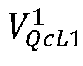
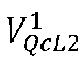
  • V QcL 1 1 ⁇ V QcL 2 1 > ⁇ the faulty line, the zone and the location of the fault are identified.
  • Step 3 The total power S F (x) in the fault path is expressed as function of the unknown fault location x on the line.
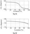
  • Step 4 If the angle of S F (x) is plotted for various locations on the line being protected, it will produce a plot similar to the one in Fig. 5A , when there is actually a fault on the line. The angle will cross zero at the actual fault location. For locations on the line before the fault point the angle will have a positive value and for locations on the line after the fault point the angle will have a negative value. If the fault is on line 1, the plot of the angle will not have a zero crossing as exemplarily shown in Fig. 5B .
  • ⁇ ⁇ SF L 2 ⁇ S F 0 ⁇ S F z b
  • Fig. 5A shows a diagram of the total fault path power angle ⁇ S F over the location on the line in percentage of the total line length assuming that the fault is on line 2. As can be seen by the zero crossing, the fault can be determined to be at 60% of the total protected line length of line 2.
  • Fig. 5B shows a diagram of the total fault path power angle ⁇ S F over the location on the line in percentage of the total line length assuming that the fault is on line 1. No zero crossing can be observed.
  • V Qc 1 x I QL 1 c 1 x V Qc 1 x I QL 2 c 1 x A L 1 1 1 1 ⁇ x B L 1 1 1 ⁇ x 0 0 C L 1 1 1 ⁇ x D L 1 1 1 1 ⁇ x 0 0 0 0 A L 2 1 1 1 ⁇ x B L 2 1 1 1 ⁇ x 0 0 C L 2 1 1 ⁇ x D L 2 1 1 1 ⁇ x V FL 1 c 1 x I FQL 1 c 1 x V FL 2 c 1 x I FQL 2 c 1 x I FQL 2 c 1 x I FQL 2 c 1 x x
  • I FQL 2 c 1 x A L 1 0 1 ⁇ x V FL 1 c 1 x B L 1 1 1 ⁇ x I FQL 1 c 1 x ⁇ A L 2 1 1 ⁇ x V FL 2 c 1 x B L 2 1 1 ⁇ x
  • V FL 1 c 1 x A L 1 1 x V P 1 + B L 1 1 x I PL 1 1 from equation (1)
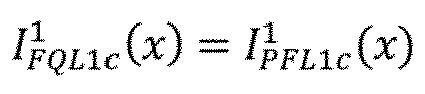
  • I FQL 1 c 1 x I PFL 1 c 1 x since there is no fault assumed in line 1 and V FL 2 c 1 x is calculated in equation (2).
  • I Fc 1 x The total positive sequence fault path current on the faulty line 2, I Fc 1 x , can be written as a function of x as below.
  • I Fc 1 x I PFL 2 c 1 x + I FQL 2 c 1 x
  • the negative sequence fault point voltage V FL 2 c 2 and the negative sequence fault path current I Fc 2 can be calculated similar to the positive sequence derivations, by replacing all positive sequence quantities with negative sequence quantities.
  • the negative sequence networks for both the lines are also decoupled.
  • the zero sequence fault point voltage on the faulty line (here, line 2), V FL 2 c 0 , can be calculated as follows.
  • V FL 1 c 0 x I PFL 1 c 0 x V FL 2 c 0 x I PFL 2 c 0 x A L 1 0 x B L 1 0 x A m 0 x B m 0 x C L 1 0 x D L 1 0 x C m 0 x D m 0 x A m 0 x B m 0 x A L 2 0 x B L 2 0 x C m 0 x D m 0 x C L 2 0 x D L 2 0 x V P 0 I PL 1 0 V P 0 I PL 2 0
  • Equation (9) is solved to obtain the zero-sequence fault point voltage on the faulty line 2, V FL 2 c 0 , in terms of the fault location x using only the local measurements.
  • V FL 2 c 0 x A m 0 x V P 0 + B m 0 x I PL 1 0 + A L 2 0 x V P 0 + B L 2 0 x I PL 2 0
  • I PFL 2 c 0 C m 0 x V P 0 + D m 0 x I PL 1 0 + C L 2 0 x V P 0 + D L 2 0 x I PL 2 0
  • I FQL 2 c 0 x A L 1 0 1 ⁇ x ⁇ A m 0 1 ⁇ x V FL 1 c 0 x + B L 1 0 1 ⁇ x ⁇ B m 0 1 ⁇ x I FQL 1 c 0 x + A m 0 1 ⁇ x ⁇ A L 2 0 1 ⁇ x V FL 2 c 0 x B L 2 0 1 ⁇ x ⁇ B m 0 1 ⁇ x
  • the total zero sequence fault path current I Fc 0 x on the faulty line 2 can be written as a function of x .
  • I Fc 0 x I PFL 2 c 0 x + I FQL 2 c 0 x
  • ⁇ ⁇ SF L 2 ⁇ S F 0 ⁇ S F z b
  • ⁇ ⁇ SF L 2 is negative, the fault is determined to be on line 2.
  • ⁇ ⁇ SF L 2 is positive, the fault is determined to be on line 1.
  • Fig. 8 shows a plot of ⁇ S F ( x ) assuming a fault on line 2 for an Ag fault at 75% of the line length from Bus P, with a high Rf 50 ⁇ . It can be seen that the plot passes through zero at the accurate fault location with minimal deviation.
  • the fault location can be identified through any numerical method, e.g., a bisection method. In this case, the fault location is identified to be at 74.9% of the line length which means that the error is only 0.1%.
  • Fig. 9 is a further flow chart of an embodiment according to the present disclosure. For detailed explanations and calculations, reference is made to the above.
  • a first step of the fault detection it is determined whether an external fault is existent by calculating whether the difference between the positive bus voltages V QcL 1 1 ⁇ V QcL 2 1 is higher or lower than a predetermined threshold C. In case the difference is smaller than the threshold 6, the fault is determined to be an external fault ("no"). In case the difference is higher than the threshold 6, it is proceeded with determining the faulty line.
  • the fault is determined to be on line 2.
  • the fault location can be determined using the zero crossing as described above.
  • the fault is determined to be on line 1.
  • the fault location can be determined using the zero crossing as described above.
  • An embodiment of the present disclosure as shown in the flowchart of Fig. 10 relates to a method for determining a fault in a double-circuit line 2 comprising a first line L1 and a second line L2.
  • the method comprises calculating M1 a first angle of a power at a beginning of a monitored line length of the first line L1, calculating M2 a second angle of a power at an end of the monitored line length of the first line L1, multiplying M3 the first angle and the second angle to calculate a first fault factor, and determining M4 whether the fault is on the first or second line L2 based on a polarity of the first fault factor.
  • the multiplication step M3 may also be another mathematical operation such as a division, any other logical operation or may be performed using a truth table
  • the line numbering line 1 and line 2 is not to be seen as restricting and can be inverted as necessary.
  • the second angle of a power at an end of the monitored line length may be ⁇ S F ( z b )
  • z b is the location on the monitored line length as described above with 0 ⁇ z b ⁇ 1.
  • the beginning of the line length may be a bus connecting the energy source (e.g., IBR) or another element to the line.
  • the end of the line length may be a bus connecting the line to a grid, an energy source or another element.
  • the monitored line length may be 100% of the line length (i.e., the actual line length from bus to bus) or a part thereof.
  • the beginning of the monitored line length may be at 20% of the (actual) line length, preferably at 10% and more preferably at 0%
  • the end of the monitored line length may be at 80% of the (actual) line length, preferably at 90%, more preferably at 95% and more preferably at 100%. Combinations thereof may also be possible.
  • a preferred monitored line length may be 0-80% of the actual line length. It is thus understood that the term "beginning/end of the line length" as used herein may also refer to "beginning/end of the monitored line length" which may not necessarily coincide as outlined above.
  • the polarity comprises a sign of the first fault factor.
  • the fault is determined to be on the first line L1 in case the sign of the first fault factor is negative, and the fault is determined to be on the second line L2 in case the sign of the first fault factor is positive.
  • the method further comprises acquiring local voltage and current measurements of the first and second line L2, wherein the calculation of the first angle and the second angle are performed using the local voltage and current measurements of the first and second line L2.
  • the method further comprises calculating a fault angle over the complete monitored line length of the line having the fault, wherein the location of the fault is determined based on a zero crossing of the fault angle.
  • the fault angle is ⁇ S F ( x ) , wherein 0 ⁇ x ⁇ z b .
  • the method further comprises acquiring local voltage and current measurements of the first and second line L2, calculating a first bus voltage at the end of the monitored line length of the first line L1 based on the local voltage and current measurements of the first line L1, calculating a second bus voltage at an end of a monitored line length of the second line L2 based on the local voltage and current measurements of the second line L2 and determining whether the fault is inside or outside of the monitored line length based on the first and second bus voltage.
  • the buses may be P and/or Q.
  • the first bus voltage may be V QcL 1 1
  • the second bus voltage may be V QcL 2 1 .
  • the fault is determined to be outside of the monitored line length in case a difference between a norm of the first bus voltage and a norm of the second bus voltage is equal or less than a predetermined threshold and the fault is determined to be inside of the monitored line length in case a difference between a norm of the first bus voltage and a norm of the second bus voltage is higher than the predetermined threshold.
  • the norm may be V QcL 1 1 ⁇ V QcL 2 1 and the threshold may be C.
  • the monitored line length of the first line L1 and the second line L2 are equal.
  • the method further comprises calculating a third angle of a power at a beginning of a monitored line length of the second line L2, calculating a fourth angle of a power at an end of the monitored line length of the second line L2, multiplying the third angle and the fourth angle to calculate a second fault factor, and determining whether the fault is on the first or second line L2 based on the sign of the second fault factor.
  • the fault is determined to be on the second line L2 in case the second fault factor is negative and the fault is determined to be on the first line L1 in case the second fault factor is positive.
  • the method further comprises acquiring local voltage and current measurements of the first and second line L2, wherein the calculation of the third angle and the fourth angle are performed using the local voltage and current measurements of the first and second line L2.
  • the power is calculated as a sum of a positive sequence power, a negative sequence power and a zero sequence power of the first and/or the second line L2.
  • An embodiment of the present disclosure further relates to a device 1 for determining a fault in a double circuit line 2 comprising a first line L1 and a second line L2, wherein the device 1 is connected to the first line L1 and the second line L2.
  • the device 1 is configured to perform the method as described herein.
  • a configuration of the device is shown in Fig. 11 .
  • the device 1 comprises a processor 10 configured to calculate a first angle of a power at a beginning of a monitored line length of the first line L1, calculate a second angle of a power at an end of the monitored line length of the first line L1, multiply the first angle and the second angle to calculate a first fault factor, and determine whether the fault is on the first or second line L2 based on the first fault factor.
  • the processor 10 is configured to determine the fault to be on the first line L1 in case the first fault factor is of a first polarity, and to determine the fault to be on the second line L2 in case the sign of the first fault factor is of a second polarity.
  • the polarity comprises a sign of the first fault factor.
  • the processor 10 is configured to determine the fault to be on the first line L1 in case the sign of the first fault factor is negative, and to determine the fault to be on the second line L2 in case the sign of the first fault factor is positive.
  • the processor 10 is further configured to acquire local voltage and current measurements of the first and second line L2, and to perform the calculation of the first angle and the second angle using the local voltage and current measurements of the first and second line L2.
  • the processor 10 is configured to calculate a fault angle over the complete monitored line length of the line having the fault, and to determine the location of the fault based on a zero crossing of the fault angle.
  • the processor 10 is configured to acquire local voltage and current measurements of the first and second line L2, calculate a first bus voltage at the end of the monitored line length of the first line L1 based on the local voltage and current measurements of the first line L1, calculate a second bus voltage at an end of a monitored line length of the second line L2 based on the local voltage and current measurements of the second line L2 and determine whether the fault is inside or outside of the monitored line length based on the first and second bus voltage.
  • the processor 10 is configured to determine the fault to be outside of the monitored line length in case a difference between a norm of the first bus voltage and a norm of the second bus voltage is equal or less than a predetermined threshold and to determine the fault to be inside of the monitored line length in case a difference between a norm of the first bus voltage and a norm of the second bus voltage is higher than the predetermined threshold.
  • the monitored line length of the first line L1 and the second line L2 are equal.
  • the processor 10 is configured to calculate a third angle of a power at a beginning of a monitored line length of the second line L2, calculate a fourth angle of a power at an end of the monitored line length of the second line L2, multiply the third angle and the fourth angle to calculate a second fault factor, and determine whether the fault is on the first or second line L2 based on the sign of the second fault factor.
  • the processor 10 is configured to determine the fault to be on the second line L2 in case the second fault factor is negative and to determine the fault to be on the first line L1 in case the second fault factor is positive.
  • the processor 10 is configured to acquire local voltage and current measurements of the first and second line L2, and to perform the calculation of the third angle and the fourth angle using the local voltage and current measurements of the first and second line L2.
  • the processor 10 is configured to calculate the poweras a sum of a positive sequence power, a negative sequence power and a zero sequence power of the first and/or the second line L2.
  • the disclosure also relates to a system for determining a fault in a double circuit line 2 comprising a first line L1 and a second line L2 and the device 1 as described above.
  • the proposed method, device and system are very minimally impacted by magnitude of fault resistance. They provide much better fault resistance coverage when compared to existing and proposed distance protection methods, devices and systems.
  • the present disclosure additionally provides accurate fault location.
  • any reference to an element herein using a designation such as "first,” “second,” and so forth does not generally limit the quantity or order of those elements. Rather, these designations can be used herein as a convenient means of distinguishing between two or more elements or instances of an element. Thus, a reference to first and second elements does not mean that only two elements can be employed, or that the first element must precede the second element in some manner.

Landscapes

  • Physics & Mathematics (AREA)
  • General Physics & Mathematics (AREA)
  • Locating Faults (AREA)

Abstract

The present disclosure relates to a method for determining a fault in a double-circuit line comprising a first line and a second line. The method comprises calculating a first angle of a power at a beginning of a monitored line length of the first line, calculating a second angle of a power at an end of the monitored line length of the first line, performing an operation with the first angle and the second angle to calculate a first fault factor, and determining whether the fault is on the first or second line based on a polarity of the first fault factor. The disclosure further relates to a corresponding device and system.

Description

  • The present disclosure relates to a method, device and system for determining a fault in a double-circuit line. In particular, the present disclosure relates to secure distance protection and accurate fault location for double-circuit lines connected to conventional and/or renewable energy sources.
  • Double-circuit lines are widely used on transmission systems due to their significant efficiency, reliability, economic and environmental advantages over single-circuit lines. For example, currently, more than 50% of the transmission line circuit length in India is constituted of 400 kV and 765 kV lines [1], of which a majority are double circuit lines. However, due to the mutual coupling effects between the two circuits, the transient signals induced on the two circuits due to a fault on one circuit are quite different from those encountered on a single-circuit line. This makes the protection of these lines more complicated.
  • Currently, the most commonly used protection techniques for double-circuit transmission lines are a separate current differential protection for each line together with a distance protection technique as backup [2]. The former one is a unit protection which is dependent on communication between the two terminals. A non-unit protection based only on local measurements, like distance protection, is further critical and necessary. However, distance protection faces several challenges when applied to lines in systems integrated with inverter-based renewable energy resources (IBR) [3]. Integration of utility-scale renewable plants at transmission levels is increasing exponentially and hence, single-ended protection (using only local measurements) of double circuit lines in transmission systems with renewable energy resources is a problem and need of the hour.
  • Several local measurement-based protection methods have been proposed for transmission lines connected to IBRs in recent literature. Various approaches, including fixed zone setting based, adaptive zone setting based, communication assisted, modified control-based and neural network-based solutions, have been explored.
  • Improved distance relaying techniques have been proposed in [4], [5] by calculating faulted section impedance to compensate for the effect of fault resistance in the presence of remote infeed. However, these either ignore the equivalent source impedance of each end of a protected line or consider them to be homogeneous to the line impedance. This is however not true for IBR-connected systems. Improved communication assisted tripping schemes are proposed in [6], [7] for the lines emanating from IBR. However, they have latency issues associated with protection decisions and there is no solution in case of communication failure. A control-based solution is provided in [8], which regulates the fault current angle from IBR imitating the characteristics of a synchronous generator. However, it is difficult to be generalised for different renewable plants with various control schemes.
  • Apparent impedance correction methods by estimation of the non-homogeneity angle introduced by IBRs is presented in [9], [10]. These methods are developed for terminals at which IBRs are connected, with the assumption that the remote end is connected to traditional generators only. These are not generic, i.e., not applicable for lines connected to traditional generator-based grid or for lines with IBRs connected at both ends. Additionally, these methods do not address the problem of mutual coupling in double-circuit lines.
  • Generic distance protection methods which can be applied to lines connected to IBRs at either or both ends are also recently proposed in the literature. The method proposed in [13] uses a time-domain based approach which requires measurements at high sampling frequency. Retrofitting such solutions into existing installation base is challenging. Furthermore, this method as well as the source independent method proposed in [14] does not consider the mutual coupling effects in double-circuit lines.
  • Figs. 1 and 2 show exemplary double-circuit line system configurations and the particular problems associated therewith. The stepped arrows downwards each indicate the location of the fault, Vx and Ix denote voltages and currents, respectively.
  • Figs. 1 and 2 show a double-circuit line which connects an inverter-based renewable (IBR) to the grid. Fig. 1A and 1B indicate two fault scenarios. For the first fault scenario in Fig. 1A the current on line 2 flows out of the IBR into the fault through the remote end. Thus, the current IL1 seen by relay R is purely controlled in nature. In this case the traditional phasor-based distance element [11] will malfunction, whereas distance protection methods proposed for IBR-connected lines in recent literature [9], [10] will work reliably.
  • Now, consider a second fault scenario as seen in Fig. 1B. The current on line 2 is such that the current from the strong remote grid feeds into the fault through the local end. Thus, the current IL1 seen by relay R consists of a significant component from the stronger remote grid. It is not as controlled in nature as in the case of first fault scenario. In this case, the traditional distance element [11] works reliably, whereas new distance protection methods proposed for relays seeing controlled IBR currents will see limitations.
  • So, for the same system, for different fault scenarios, the performance of traditional and the proposed distance protection methods varies.
  • Fig. 2 shows a double-circuit line with a generation mix of IBR and a strong synchronous generator-based grid at both ends. In this system, the nature of the current IL1 seen by relay R depends on the penetration of the IBR at the local end at the time of fault. This in turn can depend on the time of day, weather, and many other environmental and technical factors. Thus, the current IL1 seen by relay R can be controlled or non-controlled in nature. This again creates a scenario, where, depending on various environmental and technical factors, the nature of the relay current varies, and the performance of traditional and proposed distance protection methods [9], [10] varies. It is also to be noted that when both the IBRs in Fig. 2 are feeding into the fault, the recently proposed modified distance protection methods [9], [10] are not reliable. This is because they are based on the assumption that the remote end is connected to traditional generators only and has no penetration of IBR.
  • It can be concluded from the above that the traditional distance protection method as well as the modified methods proposed in recent literature face limitation when applied to double-circuit lines connected to IBRs of configurations as shown in Figs. 1 and 2.
  • In addition to this, the modified distance protection methods proposed in recent literature for lines connected to IBRs do not address the issue of mutual coupling in double-circuit lines.
  • With increased penetration of utility-scale renewable plants at transmission level and majority of EHV lines at transmission levels being double-circuit lines, there is a need for a generic, reliable, local-measurement based line protection method for double-circuit lines connected to IBRs at either or both ends.
  • Single-ended fault location function also faces challenges when applied to lines connected to IBRs [12].
  • Hence, there is also a need for a generic, accurate, local-measurement based fault location method for double-circuit lines connected to IBRs at either or both ends.
  • The present disclosure has been made in view of the above problems.
  • The invention proposes a generic, single-ended, local measurement-based method for protection and fault location on double-circuit lines connected to IBRs at either or both ends. The method may rely on local voltage measurement and current measurements from both lines as an input (which can be sampled values obtained through process bus at digital substations based on IEC 61850). The method also incorporates the effect of mutual coupling in double-circuit lines. The disclosure also relates to a corresponding device and system.
  • The disclosure provides a generic, single-ended, local measurement-based method for protection of double-circuit lines connected to IBRs at either or both ends or conventional sources.
  • Moreover, it can provide secure and dependable protection for 100% of the line, thus eliminating the need for transfer schemes which are popularly utilised in existing distance protection in the field.
  • The disclosure considers the impact of mutual coupling effects in double-circuit lines which can potentially cause underreach or overreach in existing distance protection methods [11].
  • The proposed method is very minimally impacted by the magnitude of fault resistance. It provides much better fault resistance coverage when compared to existing and proposed distance protection methods.
  • It additionally provides accurate fault location, in particular accurate to less than 1% of the total line length.
  • The invention is specified by the independent claims. Preferred embodiments are defined in the dependent claims. In the following description, although numerous features may be designated as optional, it is nevertheless acknowledged that all features comprised in the independent claims are not to be read as optional.
  • The present disclosure relates to a method for determining a fault in a double-circuit line comprising a first line and a second line. The method comprises calculating a first angle of a power at a beginning of a monitored line length of the first line, calculating a second angle of a power at an end of the monitored line length of the first line, performing an operation with the first angle and the second angle to calculate a first fault factor, and determining whether the fault is on the first or second line based on a polarity of the first fault factor.
  • Various embodiments may preferably implement the following features.
  • Preferably, the operation is a multiplication, a division, a logical operation or performed using a truth table.
  • Preferably, the fault is determined to be on the first line in case the first fault factor is of a first polarity, and the fault is determined to be on the second line in case the sign of the first fault factor is of a second polarity.
  • Preferably, the polarity comprises a sign of the first fault factor.
  • Preferably, the fault is determined to be on the first line in case the sign of the first fault factor is negative, and the fault is determined to be on the second line in case the sign of the first fault factor is positive.
  • Preferably, the method further comprises acquiring local voltage and current measurements of the first and second line, wherein the calculation of the first angle and the second angle are performed using the local voltage and current measurements of the first and second line.
  • Preferably, the method further comprises calculating a fault angle over the complete monitored line length of the line having the fault, wherein the location of the fault is determined based on a zero crossing of the fault angle.
  • Preferably, the method further comprises acquiring local voltage and current measurements of the first and second line, calculating a first bus voltage at the end of the monitored line length of the first line based on the local voltage and current measurements of the first line, calculating a second bus voltage at an end of a monitored line length of the second line based on the local voltage and current measurements of the second line and determining whether the fault is inside or outside of the monitored line length based on the first and second bus voltage.
  • Preferably, the fault is determined to be outside of the monitored line length in case a difference between a norm of the first bus voltage and a norm of the second bus voltage is equal or less than a predetermined threshold and the fault is determined to be inside of the monitored line length in case a difference between a norm of the first bus voltage and a norm of the second bus voltage is higher than the predetermined threshold.
  • Preferably, the monitored line length of the first line and the second line are equal.
  • Preferably, the method further comprises calculating a third angle of a power at a beginning of a monitored line length of the second line, calculating a fourth angle of a power at an end of the monitored line length of the second line, multiplying the third angle and the fourth angle to calculate a second fault factor, and determining whether the fault is on the first or second line based on the sign of the second fault factor.
  • Preferably, the fault is determined to be on the second line in case the second fault factor is negative and the fault is determined to be on the first line in case the second fault factor is positive.
  • Preferably, the method further comprises acquiring local voltage and current measurements of the first and second line, wherein the calculation of the third angle and the fourth angle are performed using the local voltage and current measurements of the first and second line.
  • Preferably, the power is calculated as a sum of a positive sequence power, a negative sequence power and a zero sequence power of the first and/or the second line.
  • The disclosure further relates to a device for determining a fault in a double circuit line comprising a first line and a second line, wherein the device is connected to the first line and the second line and comprises a processor configured to calculate a first angle of a power at a beginning of a monitored line length of the first line, calculate a second angle of a power at an end of the monitored line length of the first line, performing an operation with the first angle and the second angle to calculate a first fault factor, and determine whether the fault is on the first or second line based on the first fault factor.
  • Various embodiments may preferably implement the following features.
  • Preferably, the operation is multiplication, a division, a logical operation or performed using a truth table.
  • Preferably, the processor is configured to determine the fault to be on the first line in case the first fault factor is of a first polarity, and to determine the fault to be on the second line in case the sign of the first fault factor is of a second polarity.
  • Preferably, the polarity comprises a sign of the first fault factor.
  • Preferably, the processor is configured to determine the fault to be on the first line in case the sign of the first fault factor is negative, and to determine the fault to be on the second line in case the sign of the first fault factor is positive.
  • Preferably, the processor is further configured to acquire local voltage and current measurements of the first and second line, and to perform the calculation of the first angle and the second angle using the local voltage and current measurements of the first and second line.
  • Preferably, the processor is configured to calculate a fault angle over the complete monitored line length of the line having the fault, and to determine the location of the fault based on a zero crossing of the fault angle.
  • Preferably, the processor is configured to acquire local voltage and current measurements of the first and second line, calculate a first bus voltage at the end of the monitored line length of the first line based on the local voltage and current measurements of the first line, calculate a second bus voltage at an end of a monitored line length of the second line based on the local voltage and current measurements of the second line and determine whether the fault is inside or outside of the monitored line length based on the first and second bus voltage.
  • Preferably, the processor is configured to determine the fault to be outside of the monitored line length in case a difference between a norm of the first bus voltage and a norm of the second bus voltage is equal or less than a predetermined threshold and to determine the fault to be inside of the monitored line length in case a difference between a norm of the first bus voltage and a norm of the second bus voltage is higher than the predetermined threshold.
  • Preferably, the monitored line length of the first line and the second line are equal.
  • Preferably, the processor is configured to calculate a third angle of a power at a beginning of a monitored line length of the second line, calculate a fourth angle of a power at an end of the monitored line length of the second line, multiply the third angle and the fourth angle to calculate a second fault factor, and determine whether the fault is on the first or second line based on the sign of the second fault factor.
  • Preferably, the processor is configured to determine the fault to be on the second line in case the second fault factor is negative and to determine the fault to be on the first line in case the second fault factor is positive.
  • Preferably, the processor is configured to acquire local voltage and current measurements of the first and second line, and to perform the calculation of the third angle and the fourth angle using the local voltage and current measurements of the first and second line.
  • Preferably, the processor is configured to calculate the power as a sum of a positive sequence power, a negative sequence power and a zero sequence power of the first and/or the second line.
  • The disclosure also relates to a system for determining a fault in a double circuit line comprising a first line and a second line and the device as described above.
  • Other aspects, features, and advantages will be apparent from the summary above, as well as from the description that follows, including the figures and the claims.
    • Figs. 1 and 2 show exemplary double-circuit line system configurations.
    • Fig. 3 shows a flow chart of a high-level design of an embodiment of the present disclosure.
    • Fig. 4 shows a double circuit transmission line test system according to an embodiment of the present disclosure.
    • Figs. 5A and 5B are plots of an angle of the total fault path power over the line length according to an embodiment of the present disclosure.
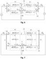
    • Fig. 6 is a positive sequence equivalent network after a fault according to an embodiment of the present disclosure.
    • Fig. 7 is a zero sequence equivalent network after a fault according to an embodiment of the present disclosure.
    • Fig. 8 is a plot of an angle of the total fault path power over the line length according to an embodiment of the present disclosure.
    • Fig. 9 is a flowchart of a method according to an embodiment of the present disclosure.
    • Fig. 10 is a flowchart of a method according to an embodiment of the present disclosure.
    • Fig. 11 shows a configuration according to an embodiment of the present disclosure.
  • In the following, the terms "first/second line", "L1/L2" and "line 1/line 2" denote the same and may be used interchangeably. Moreover, a voltage is denoted by the symbol "V" while a current is denoted by the symbol "1".
  • Fig. 3 shows a flow chart of a high-level design of an embodiment of the present disclosure. In this embodiment, the proposed method identifies whether a fault is in the pre-determined zone of protection of the line being protected in a double-circuit line 2 using local voltage and current measurements from both the lines. In particular, the method includes acquiring S1 local voltage and current measurements from line 1 and/or 2, performing S2 a protection algorithm and identifying S3 a fault line and fault zone, determining a fault location, and acquiring a trip decision.
  • Fig. 4 shows a double circuit transmission line test system to further describe the principle of the present disclosure. The following refers to an embodiment of the present disclosure.
  • In the example of Fig. 4, the fault is on line 2 at F at a distance x from terminal P (x is expressed as a fraction of the total line length).
  • The total power across the fault path (F to ground through RF) for a fault on a transmission line can be calculated as follows. S F = V F I F
    Figure imgb0001
  • Where, VF is the fault point voltage at F and IF is the fault path current flowing through the fault resistance RF .
  • This can be written as a sum of the individual positive, negative and zero sequence components: S F = V F 1 I F 1 + V F 2 I F 2 + V F 0 I F 0
    Figure imgb0002
  • The superscripts 1, 2 and 0 denote positive, negative and zero sequences. Since the fault path resistance RF for a fault on a transmission line is majorly resistive in nature, the angle of the total power SF will be very close to zero. This property can be used to identify if there is a fault in a protected zone of a transmission line. The basic steps according to an embodiment are listed below.
  • Step 1: Firstly, after fault event detection, it is classified if the fault is within the terminals P and Q in Fig. 4 or external to it (i.e., bus faults and faults behind P or beyond Q). This is done by calculating the voltage at remote Bus Q from local Bus P, through line 1 and line 2 and comparing them.
  • In particular, a positive Bus Q voltage from Bus P through line 1, V QcL 1 1
    Figure imgb0003
    , is calculated: V QcL 1 1 = A L 1 1 V P 1 + B L 1 1 I PL 1 1
    Figure imgb0004
  • Moreover, the positive Bus Q voltage from Bus P through line 2, V QcL 2 1
    Figure imgb0005
    , is calculated: V QcL 2 1 = A L 2 1 V P 1 + B L 2 1 I PL 2 1
    Figure imgb0006
    where A L 1 1 = D L 1 1 = cosh γ 1 L , B L 1 1 = Z c 1 sinh γ 1 L , D L 1 1 = 1 z c 1 sinh γ 1 L
    Figure imgb0007
    Z c 1 = r 1 + j ωl 1 j ωc 1 , γ 1 = r 1 + j ωl 1 j ωc 1
    Figure imgb0008
    and r 1, l 1 and c 1 are positive sequence resistance, inductance and capacitance per unit length of the line.
  • Subscripts L1 and L2 denote line 1 and line 2, respectively. Superscript 1 denotes a positive sequence component.
  • If the fault is behind Bus P or beyond Bus Q, both these calculated voltages will be almost equal and in particular, a difference will be less than a pre-set threshold, i.e., V QcL 1 1 V QcL 2 1 <
    Figure imgb0009
    .
  • If V QcL 1 1 V QcL 2 1 >
    Figure imgb0010
    , the faulty line, the zone and the location of the fault are identified.
  • Otherwise, the fault is identified to be an external fault.
  • Step 2: If the fault is determined to be between Bus P and Q, assuming that the fault is on line 2, the sequence components of fault point voltage (VF ) and current (IF) are expressed as a function of the unknown fault location x on the line: V F 1 x , V F 2 x , V F 0 x , I F 1 x , I F 2 x , I F 0 x
    Figure imgb0011
    .
  • The superscripts 1, 2 and 0 denote positive, negative and zero sequences, respectively.
  • Step 3: The total power SF(x) in the fault path is expressed as function of the unknown fault location x on the line. S F x = S F 1 x + S F 2 x + S F 0 x = V F 1 x I F 1 x + V F 2 x I F 2 x + V F 0 x I F 0 x
    Figure imgb0012
  • Step 4: If the angle of SF(x) is plotted for various locations on the line being protected, it will produce a plot similar to the one in Fig. 5A, when there is actually a fault on the line. The angle will cross zero at the actual fault location. For locations on the line before the fault point the angle will have a positive value and for locations on the line after the fault point the angle will have a negative value. If the fault is on line 1, the plot of the angle will not have a zero crossing as exemplarily shown in Fig. 5B.
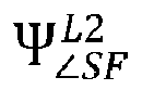
  • To identify if the fault is on line 2 (since in this example, derivations are made on the assumption that the fault is on line 2) a factor Ψ SF L 2
    Figure imgb0013
    is calculated as below: ψ SF L 2 = S F 0 S F z b
    Figure imgb0014
  • Where, ∠SF (0) is the angle of the total fault path power calculated assuming that the fault is the local terminal (i.e., substituting x = 0 in equation 5) and ∠SF (zb ) is the angle of the total fault path power calculated assuming that the fault is the boundary of the zone of protection (i.e., substituting x = zb in equation 5). The zone of boundary can be set to cover the full line length (zb =1) or a particular percentage of the line, e.g., 80% (zb =0.8).
  • As can be seen from Fig. 5, if the fault is on the protected zone of the line 2, Ψ SF L 2
    Figure imgb0015
    will be negative. If the fault is on the other line, i.e., line 1, Ψ SF L 2
    Figure imgb0016
    will be positive. Thus, if Ψ SF L 2
    Figure imgb0017
    • is negative, the fault is determined to be on line 2, and
    • Ψ SF L 2
      Figure imgb0018
      is positive, the fault is determined to be on line 1.
  • The factor Ψ SF L 2
    Figure imgb0019
    may also be calculated by a division, a logical operation or using a truth table.
  • Fig. 5A shows a diagram of the total fault path power angle ∠SF over the location on the line in percentage of the total line length assuming that the fault is on line 2. As can be seen by the zero crossing, the fault can be determined to be at 60% of the total protected line length of line 2.
  • Fig. 5B shows a diagram of the total fault path power angle ∠SF over the location on the line in percentage of the total line length assuming that the fault is on line 1. No zero crossing can be observed.
  • In an embodiment, if faults on line 1 and 2 are assumed, two factors Ψ SF L 1
    Figure imgb0020
    and Ψ SF L 2
    Figure imgb0021
    for lines 1 and 2, respectively, may be obtained. A decision may be made as below.
    Ψ SF L 1
    Figure imgb0022
    Ψ SF L 2
    Figure imgb0023
    Decision
    negative positive Fault on line 1
    positive negative Fault on line 2
  • A more detailed derivation of ∠SF (x) to calculate Ψ SF L 2
    Figure imgb0024
    assuming a fault on line 2 is described below.
  • A similar derivation can be carried out assuming the fault is on line 1 to calculate Ψ SF L 1
    Figure imgb0025
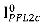
    .
  • The positive sequence network derivations will be described referring to Fig. 6.
  • First, a positive sequence fault point voltage V FL 2 c 1
    Figure imgb0026
    on the faulty line 2 is calculated.
  • For the positive sequence network P1 between terminal P and fault bus F (see Fig.6), the following relations can be formed: V FL 1 c 1 x I PFL 1 c 1 x V FL 2 c 1 x I PFL 2 c 1 x = A L 1 1 x B L 1 1 x 0 0 C L 1 1 x D L 1 1 x 0 0 0 0 A L 2 1 x B L 2 1 x 0 0 C L 2 1 x D L 2 1 x V P 1 I PL 1 1 V P 1 I PL 2 1
    Figure imgb0027
    where A L 1 1 x = D L 1 1 x = cosh γ 1 xL , B L 1 1 x = Z c 1 sinh γ 1 xL , C L 1 1 x = 1 z c 1 sinh γ 1 xL
    Figure imgb0028
    Z c 1 = r 1 + j ωl 1 j ωc 1 , γ 1 = r 1 + j ωl 1 j ωc 1
    Figure imgb0029
    and r 1, l 1 and c 1 are positive sequence resistance, inductance, and capacitance, respectively, per unit length of the line.
  • Solving equation (1) above results in the positive-sequence fault point voltage V FL 2 c 1
    Figure imgb0030
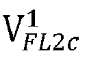
    on the faulty line 2 in terms of the fault location x using only the local measurements. V FL 2 c 1 x = A L 2 1 x V P 1 + B L 2 1 x I PL 2 1
    Figure imgb0031
  • Next, the positive sequence fault path current I Fc 1
    Figure imgb0032
    on the faulty line is calculated.
  • The fault current fed from the local terminal P, I PFL 2 c 1
    Figure imgb0033
    , can be obtained from the second row of equation (1) above. I PFL 2 c 1 x = C L 2 1 x V P 1 + D L 2 1 x I PL 2 1
    Figure imgb0034
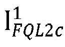
  • Now, to obtain a positive-sequence component of the fault current fed from the remote terminal Q, I FQL 2 c 1
    Figure imgb0035
    , the port equations for port P2 in a positive-sequence equivalent network in Fig. 6 can be written as follows. V Qc 1 x I QL 1 c 1 x V Qc 1 x I QL 2 c 1 x = A L 1 1 1 x B L 1 1 1 x 0 0 C L 1 1 1 x D L 1 1 1 x 0 0 0 0 A L 2 1 1 x B L 2 1 1 x 0 0 C L 2 1 1 x D L 2 1 1 x V FL 1 c 1 x I FQL 1 c 1 x V FL 2 c 1 x I FQL 2 c 1 x
    Figure imgb0036
  • After equating V Qc 1 x
    Figure imgb0037
    calculated from the first and third rows in equation (4), the following expression for I FQL 2 c 1
    Figure imgb0038
    can be derived. I FQL 2 c 1 x = A L 1 0 1 x V FL 1 c 1 x B L 1 1 1 x I FQL 1 c 1 x A L 2 1 1 x V FL 2 c 1 x B L 2 1 1 x
    Figure imgb0039
    where V FL 1 c 1 x = A L 1 1 x V P 1 + B L 1 1 x I PL 1 1
    Figure imgb0040
    from equation (1), I FQL 1 c 1 x = I PFL 1 c 1 x
    Figure imgb0041
    since there is no fault assumed in line 1 and V FL 2 c 1 x
    Figure imgb0042
    is calculated in equation (2).
  • The total positive sequence fault path current on the faulty line 2, I Fc 1 x
    Figure imgb0043
    , can be written as a function of x as below. I Fc 1 x = I PFL 2 c 1 x + I FQL 2 c 1 x
    Figure imgb0044
  • Next, the positive sequence fault path power S F 1 x
    Figure imgb0045
    is calculated.
  • Using the calculated positive sequence fault point voltage V FL 2 c 1
    Figure imgb0046
    and the fault path current I Fc 1
    Figure imgb0047
    , the total positive sequence fault path power can be calculated as S F 1 x = V FL 2 c 1 x I Fc 1 x
    Figure imgb0048
  • Next, the negative sequence network derivations will be described.
  • The negative sequence fault point voltage V FL 2 c 2
    Figure imgb0049
    and the negative sequence fault path current I Fc 2
    Figure imgb0050
    can be calculated similar to the positive sequence derivations, by replacing all positive sequence quantities with negative sequence quantities. The negative sequence networks for both the lines are also decoupled.
  • Using the calculated negative sequence fault point voltage V FL 2 c 2
    Figure imgb0051
    and the fault path current I Fc 2 ,
    Figure imgb0052
    , the total negative sequence fault path power can be calculated as S F 2 x = F FL 2 c 2 x I Fc 2 x
    Figure imgb0053
  • Next, the zero sequence network derivations will be described with reference to Fig. 7.
  • The zero sequence fault point voltage on the faulty line (here, line 2), V FL 2 c 0
    Figure imgb0054
    , can be calculated as follows.
  • Zero sequence networks of both the lines are not decoupled since the sum of zero-sequence currents flowing through a circuit is non-zero. Hence, the equations for P1 for the zero-sequence network shown in Fig. 7 can be written as below. V FL 1 c 0 x I PFL 1 c 0 x V FL 2 c 0 x I PFL 2 c 0 x = A L 1 0 x B L 1 0 x A m 0 x B m 0 x C L 1 0 x D L 1 0 x C m 0 x D m 0 x A m 0 x B m 0 x A L 2 0 x B L 2 0 x C m 0 x D m 0 x C L 2 0 x D L 2 0 x V P 0 I PL 1 0 V P 0 I PL 2 0
    Figure imgb0055
  • Equation (9) is solved to obtain the zero-sequence fault point voltage on the faulty line 2, V FL 2 c 0
    Figure imgb0056
    , in terms of the fault location x using only the local measurements. V FL 2 c 0 x = A m 0 x V P 0 + B m 0 x I PL 1 0 + A L 2 0 x V P 0 + B L 2 0 x I PL 2 0
    Figure imgb0057
  • Next, the zero sequence fault path current I Fc 0
    Figure imgb0058
    on the faulty line is calculated.
  • The zero-sequence component of the fault current fed from the local terminal P, I PFL 2 c 0
    Figure imgb0059
    can be obtained from the last row of equation (9). I PFL 2 c 0 x = C m 0 x V P 0 + D m 0 x I PL 1 0 + C L 2 0 x V P 0 + D L 2 0 x I PL 2 0
    Figure imgb0060
  • Now, to obtain the zero-sequence component of the fault current fed from the remote terminal Q, I FQL 2 c 0
    Figure imgb0061
    the port equations for port P2 in the zero-sequence equivalent network in Fig. 7 can be written as follows. V Qc 0 x I QL 1 c 0 x V Qc 0 x I QL 2 c 0 x = A L 1 0 1 x B L 1 0 1 x A m 0 1 x B m 0 1 x C L 1 0 1 x D L 1 0 1 x C m 0 1 x D m 0 1 x A m 0 1 x B m 0 1 x A L 2 0 1 x B L 2 0 1 x C m 0 1 x D m 0 1 x C L 2 0 1 x D L 2 0 1 x V FL 1 c 0 x I FQL 1 c 0 x V FL 2 c 0 x I FQL 2 c 0 x
    Figure imgb0062
  • After equating V Qc 0 x
    Figure imgb0063
    calculated from the first and third rows in equation (12), the following expression shown below can be derived for I FQL 2 c 0
    Figure imgb0064
    . I FQL 2 c 0 x = A L 1 0 1 x A m 0 1 x V FL 1 c 0 x + B L 1 0 1 x B m 0 1 x I FQL 1 c 0 x + A m 0 1 x A L 2 0 1 x V FL 2 c 0 x B L 2 0 1 x B m 0 1 x
    Figure imgb0065
  • The total zero sequence fault path current I Fc 0 x
    Figure imgb0066
    on the faulty line 2 can be written as a function of x. I Fc 0 x = I PFL 2 c 0 x + I FQL 2 c 0 x
    Figure imgb0067
  • Next, the zero sequence fault path power S F 0 x
    Figure imgb0068
    is calculated.
  • Using the calculated zero sequence fault point voltage V FL 2 c 0
    Figure imgb0069
    and fault path current I Fc 0
    Figure imgb0070
    , the total zero sequence fault path power can be calculated as: S F 0 x = V FL 2 c 0 x I Fc 0 x
    Figure imgb0071
  • Now, the logic for the trip decision, i.e., whether to operate a circuit breaker or similar grid element, will be described.
  • In order to identify whether the fault is on line 2, a factor Ψ SF L 2
    Figure imgb0072
    is calculated as shown below, ψ SF L 2 = S F 0 S F z b
    Figure imgb0073
    where ∠SF (0) is the angle of the total fault path power calculated assuming that the fault is at the local terminal (i.e., x = 0) and ∠SF (zb ) is the angle of total fault path power calculated assuming that the fault is the boundary of the zone of protection (x = zb). As described above, zone of protection can be sent to cover the full line length (zb =1) or a particular percentage of the line, e.g., 80% (zb =0.8). Ψ SF L 2
    Figure imgb0074
    is negative, the fault is determined to be on line 2. Ψ SF L 2
    Figure imgb0075
    is positive, the fault is determined to be on line 1.
  • Next, the identification of the fault location will be described.
  • In addition to protection, the method as disclosed herein also provides the fault location as an output. Fig. 8 shows a plot of ∠SF (x) assuming a fault on line 2 for an Ag fault at 75% of the line length from Bus P, with a high Rf 50Ω. It can be seen that the plot passes through zero at the accurate fault location with minimal deviation. Thus, the fault location can be identified through any numerical method, e.g., a bisection method. In this case, the fault location is identified to be at 74.9% of the line length which means that the error is only 0.1%.
  • The above calculations have mainly been described with reference to line 2. However, the calculations are equally applicable to line 1.
  • Fig. 9 is a further flow chart of an embodiment according to the present disclosure. For detailed explanations and calculations, reference is made to the above.
  • In a first step of the fault detection, it is determined whether an external fault is existent by calculating whether the difference between the positive bus voltages V QcL 1 1 V QcL 2 1
    Figure imgb0076
    is higher or lower than a predetermined threshold C. In case the difference is smaller than the threshold 6, the fault is determined to be an external fault ("no"). In case the difference is higher than the threshold 6, it is proceeded with determining the faulty line.
  • In particular, Ψ SF L 2 < 0
    Figure imgb0077
    and Ψ SF L 1 > 0
    Figure imgb0078
    , the fault is determined to be on line 2. The fault location can be determined using the zero crossing as described above.
  • If Ψ SF L 1 < 0
    Figure imgb0079
    and Ψ SF L 2 > 0
    Figure imgb0080
    , the fault is determined to be on line 1. The fault location can be determined using the zero crossing as described above.
  • An embodiment of the present disclosure as shown in the flowchart of Fig. 10 relates to a method for determining a fault in a double-circuit line 2 comprising a first line L1 and a second line L2. The method comprises calculating M1 a first angle of a power at a beginning of a monitored line length of the first line L1, calculating M2 a second angle of a power at an end of the monitored line length of the first line L1, multiplying M3 the first angle and the second angle to calculate a first fault factor, and determining M4 whether the fault is on the first or second line L2 based on a polarity of the first fault factor.
  • The multiplication step M3 may also be another mathematical operation such as a division, any other logical operation or may be performed using a truth table
  • The line numbering line 1 and line 2 is not to be seen as restricting and can be inverted as necessary.
  • For this embodiment, the first angle of a power at a beginning of a monitored line length (x = 0) may be ∠SF (0), and the second angle of a power at an end of the monitored line length may be ∠SF (zb ), wherein zb is the location on the monitored line length as described above with 0 < zb ≤ 1.
  • The first fault factor of the first line L1 may thus be Ψ SF L 1 = S F 0 S F z b
    Figure imgb0081
    .
  • The beginning of the line length may be a bus connecting the energy source (e.g., IBR) or another element to the line. Similarly, the end of the line length may be a bus connecting the line to a grid, an energy source or another element. The monitored line length may be 100% of the line length (i.e., the actual line length from bus to bus) or a part thereof. For example, the beginning of the monitored line length may be at 20% of the (actual) line length, preferably at 10% and more preferably at 0%, and the end of the monitored line length may be at 80% of the (actual) line length, preferably at 90%, more preferably at 95% and more preferably at 100%. Combinations thereof may also be possible. A preferred monitored line length may be 0-80% of the actual line length. It is thus understood that the term "beginning/end of the line length" as used herein may also refer to "beginning/end of the monitored line length" which may not necessarily coincide as outlined above.
  • In an embodiment, the fault is determined to be on the first line L1 in case the first fault factor is of a first polarity, and the fault is determined to be on the second line L2 in case the sign of the first fault factor is of a second polarity.
  • In an embodiment, the polarity comprises a sign of the first fault factor.
  • In an embodiment, the fault is determined to be on the first line L1 in case the sign of the first fault factor is negative, and the fault is determined to be on the second line L2 in case the sign of the first fault factor is positive.
  • In an embodiment, the method further comprises acquiring local voltage and current measurements of the first and second line L2, wherein the calculation of the first angle and the second angle are performed using the local voltage and current measurements of the first and second line L2.
  • In an embodiment, the method further comprises calculating a fault angle over the complete monitored line length of the line having the fault, wherein the location of the fault is determined based on a zero crossing of the fault angle.
  • Therein, the fault angle is ∠SF (x), wherein 0 ≤ xzb.
  • In an embodiment, the method further comprises acquiring local voltage and current measurements of the first and second line L2, calculating a first bus voltage at the end of the monitored line length of the first line L1 based on the local voltage and current measurements of the first line L1, calculating a second bus voltage at an end of a monitored line length of the second line L2 based on the local voltage and current measurements of the second line L2 and determining whether the fault is inside or outside of the monitored line length based on the first and second bus voltage.
  • The buses may be P and/or Q. The first bus voltage may be V QcL 1 1
    Figure imgb0082
    , and the second bus voltage may be V QcL 2 1
    Figure imgb0083
    .
  • In an embodiment, the fault is determined to be outside of the monitored line length in case a difference between a norm of the first bus voltage and a norm of the second bus voltage is equal or less than a predetermined threshold and the fault is determined to be inside of the monitored line length in case a difference between a norm of the first bus voltage and a norm of the second bus voltage is higher than the predetermined threshold.
  • The norm may be V QcL 1 1 V QcL 2 1
    Figure imgb0084
    and the threshold may be C.
  • In an embodiment, the monitored line length of the first line L1 and the second line L2 are equal.
  • In an embodiment, the method further comprises calculating a third angle of a power at a beginning of a monitored line length of the second line L2, calculating a fourth angle of a power at an end of the monitored line length of the second line L2, multiplying the third angle and the fourth angle to calculate a second fault factor, and determining whether the fault is on the first or second line L2 based on the sign of the second fault factor.
  • For this embodiment, the third angle of a power at a beginning of a monitored line length of the second line L2 (x = 0) may be ∠SF (0), and the second angle of a power at an end of the monitored line length of the second line L2 may be ∠SF (zb ), wherein zb is the location on the monitored line length as described above with 0 < zb ≤ 1.
  • The first fault factor of the second line L2 may thus be Ψ SF L 2 = S F 0 S F z b
    Figure imgb0085
    .
  • In an embodiment, the fault is determined to be on the second line L2 in case the second fault factor is negative and the fault is determined to be on the first line L1 in case the second fault factor is positive.
  • In an embodiment, the method further comprises acquiring local voltage and current measurements of the first and second line L2, wherein the calculation of the third angle and the fourth angle are performed using the local voltage and current measurements of the first and second line L2.
  • In an embodiment, the power is calculated as a sum of a positive sequence power, a negative sequence power and a zero sequence power of the first and/or the second line L2.
  • An embodiment of the present disclosure further relates to a device 1 for determining a fault in a double circuit line 2 comprising a first line L1 and a second line L2, wherein the device 1 is connected to the first line L1 and the second line L2. The device 1 is configured to perform the method as described herein. A configuration of the device is shown in Fig. 11.
  • The device 1 comprises a processor 10 configured to calculate a first angle of a power at a beginning of a monitored line length of the first line L1, calculate a second angle of a power at an end of the monitored line length of the first line L1, multiply the first angle and the second angle to calculate a first fault factor, and determine whether the fault is on the first or second line L2 based on the first fault factor.
  • In an embodiment, the processor 10 is configured to determine the fault to be on the first line L1 in case the first fault factor is of a first polarity, and to determine the fault to be on the second line L2 in case the sign of the first fault factor is of a second polarity.
  • In an embodiment, the polarity comprises a sign of the first fault factor.
  • In an embodiment, the processor 10 is configured to determine the fault to be on the first line L1 in case the sign of the first fault factor is negative, and to determine the fault to be on the second line L2 in case the sign of the first fault factor is positive.
  • In an embodiment, the processor 10 is further configured to acquire local voltage and current measurements of the first and second line L2, and to perform the calculation of the first angle and the second angle using the local voltage and current measurements of the first and second line L2.
  • In an embodiment, the processor 10 is configured to calculate a fault angle over the complete monitored line length of the line having the fault, and to determine the location of the fault based on a zero crossing of the fault angle.
  • In an embodiment, the processor 10 is configured to acquire local voltage and current measurements of the first and second line L2, calculate a first bus voltage at the end of the monitored line length of the first line L1 based on the local voltage and current measurements of the first line L1, calculate a second bus voltage at an end of a monitored line length of the second line L2 based on the local voltage and current measurements of the second line L2 and determine whether the fault is inside or outside of the monitored line length based on the first and second bus voltage.
  • In an embodiment, the processor 10 is configured to determine the fault to be outside of the monitored line length in case a difference between a norm of the first bus voltage and a norm of the second bus voltage is equal or less than a predetermined threshold and to determine the fault to be inside of the monitored line length in case a difference between a norm of the first bus voltage and a norm of the second bus voltage is higher than the predetermined threshold.
  • In an embodiment, the monitored line length of the first line L1 and the second line L2 are equal.
  • In an embodiment, the processor 10 is configured to calculate a third angle of a power at a beginning of a monitored line length of the second line L2, calculate a fourth angle of a power at an end of the monitored line length of the second line L2, multiply the third angle and the fourth angle to calculate a second fault factor, and determine whether the fault is on the first or second line L2 based on the sign of the second fault factor.
  • In an embodiment, the processor 10 is configured to determine the fault to be on the second line L2 in case the second fault factor is negative and to determine the fault to be on the first line L1 in case the second fault factor is positive.
  • In an embodiment, the processor 10 is configured to acquire local voltage and current measurements of the first and second line L2, and to perform the calculation of the third angle and the fourth angle using the local voltage and current measurements of the first and second line L2.
  • In an embodiment, the processor 10 is configured to calculate the poweras a sum of a positive sequence power, a negative sequence power and a zero sequence power of the first and/or the second line L2.
  • The disclosure also relates to a system for determining a fault in a double circuit line 2 comprising a first line L1 and a second line L2 and the device 1 as described above.
  • According to the present disclosure, a generic, single-ended, local measurement-based method for protection of double-circuit lines connected to IBRs at either or both ends or conventional sources is presented.
  • It can provide secure and dependable protection for 100% of the line, thus eliminating the need for transfer schemes which are popularly utilised in existing distance protection in the field.
  • It also takes care of the impact of mutual coupling effect in double-circuit lines which can potentially cause underreach or overreach in existing distance protection methods [11].
  • The proposed method, device and system are very minimally impacted by magnitude of fault resistance. They provide much better fault resistance coverage when compared to existing and proposed distance protection methods, devices and systems.
  • The present disclosure additionally provides accurate fault location.
  • While various embodiments of the present disclosure have been described above, it should be understood that they have been presented by way of example only, and not by way of limitation. Likewise, the various diagrams may depict an example architectural or configuration, which are provided to enable persons of ordinary skill in the art to understand exemplary features and functions of the present disclosure. Such persons would understand, however, that the present disclosure is not restricted to the illustrated example architectures or configurations, but can be implemented using a variety of alternative architectures and configurations. Additionally, as would be understood by persons of ordinary skill in the art, one or more features of one embodiment can be combined with one or more features of another embodiment described herein. Thus, the breadth and scope of the present disclosure should not be limited by any one of the above-described exemplary embodiments.
  • It is also understood that any reference to an element herein using a designation such as "first," "second," and so forth does not generally limit the quantity or order of those elements. Rather, these designations can be used herein as a convenient means of distinguishing between two or more elements or instances of an element. Thus, a reference to first and second elements does not mean that only two elements can be employed, or that the first element must precede the second element in some manner.
  • Various modifications to the implementations described in this disclosure will be readily apparent to those skilled in the art, and the general principles defined herein can be applied to other implementations without departing from the scope of this disclosure. Thus, the disclosure is not intended to be limited to the implementations shown herein, but is to be accorded the widest scope consistent with the novel features and principles disclosed herein, as recited in the claims below.
  • List of references
    1. [1] https://www.statista.com/statistics/1219587/india-share-of-transmission-line-length-by-voltage/
    2. [2] Z. Q. Bo, X. Z. Dong, B. R. J. Caunce and R. Millar, "Adaptive noncommunication protection of double-circuit line systems," in IEEE Transactions on Power Delivery, vol. 18, no. 1, pp. 43-49, Jan. 2003
    3. [3] A. Hooshyar, M. A. Azzouz and E. F. EI-Saadany, "Distance Protection of Lines Emanating From Full-Scale Converter-Interfaced Renewable Energy Power Plants-Part I: Problem Statement," in IEEE Transactions on Power Delivery, vol. 30, no. 4, pp. 1770-1780, Aug. 2015
    4. [4] Y. Liang, Z. Lu, W. Li, W. Zha and Y. Huo, "A novel fault impedance calculation method for distance protection against fault resistance", IEEE Trans. Power Del., vol. 35, no. 1, pp. 396-407, Feb. 2020
    5. [5] J. Ma, W. Ma, Y. Qiu and J. S. Thorp, "An adaptive distance protection scheme based on the voltage drop equation", IEEE Trans. Power Del., vol. 30, no. 4, pp. 1931-1940, Aug. 2015
    6. [6] A. Hooshyar, M. A. Azzouz and E. F. EI-Saadany, "Distance protection of lines connected to induction generator-based wind farms during balanced faults", IEEE Trans. Sustain. Energy, vol. 5, no. 4, pp. 1193-1203, Oct. 2014
    7. [7] A. Hooshyar, M. A. Azzouz and E. F. EI-Saadany, "Distance protection of lines emanating from full-scale converter-interfaced renewable energy power plants-Part II: Solution description and evaluation", IEEE Trans. Power Del., vol. 30, no. 4, pp. 1781-1791, Aug. 2015
    8. [8] A. Banaiemoqadam, A. Hooshyar and M. A. Azzouz, "A control-based solution for distance protection of lines connected to converter-interfaced sources during asymmetrical faults", IEEE Trans. Power Del., vol. 35, no. 3, pp. 1455-1466, Jun. 2020.
    9. [9] S. Paladhi and A. K. Pradhan, "Adaptive distance protection for lines connecting converter-interfaced renewable plants", IEEEJ. Emerg. Sel. Topics Power Electron., vol. 9, no. 6, pp. 7088-7098, Dec. 2021
    10. [10] N. George, O. D. Naidu and A. K. Pradhan, "Distance Protection for Lines Connecting Converter Interfaced Renewable Power Plants: Adaptive to Grid-end Structural Changes," in IEEE Transactions on Power Delivery, vol. 38, no. 3, pp. 2011-2021, June 2023
    11. [11] Application manual, Line distance protection REL 670.2" [Online]. Available:https://library.e.abb.com/public/8c1eb95cc50243c4c1257d9300423926/1MRK506 338-UUS_-_en_Application_manual__Line_distance_protection_REL670_2.0_ANSI.pdf
    12. [12]L. Kukkala, O. D. Naidu, A. V and S. Sharma, "Single Ended Fault Locator for Power Transmission Lines Connected with Inverter Based Resources: Problems and Mitigation Approach," 2022 22nd National Power Systems Conference (NPSC), New Delhi, India, 2022, pp. 685-690
    13. [13]P. Adhikari, S. Brahma and P. H. Gadde, "Source-Agnostic Time-Domain Distance Relay," in IEEE Transactions on Power Delivery, vol. 37, no. 5, pp. 3620-3629, Oct. 2022.
    14. [14]S. Paladhi, J. R. Kurre and A. K. Pradhan, "Source-Independent Zone-1 Protection for Converter-Dominated Power Networks," in IEEE Transactions on Power Delivery, 2022.

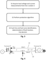
Claims (15)

  1. Method for determining a fault in a double-circuit line (2) comprising a first line (L1) and a second line (L2), the method comprising:
    calculating (M1) a first angle of a power at a beginning of a monitored line length of the first line (L1),
    calculating (M2) a second angle of a power at an end of the monitored line length of the first line (L1),
    performing (M3) an operation with the first angle and the second angle to calculate a first fault factor, and
    determining (M4) whether the fault is on the first or second line (L1, L2) based on a polarity of the first fault factor.
  2. Method according to claim 1, wherein the operation is a multiplication, and
    wherein the fault is determined to be on the first line (L1) in case the first fault factor is of a first polarity, and the fault is determined to be on the second line (L2) in case the sign of the first fault factor is of a second polarity.
  3. Method according to claim 1 or 2, wherein the polarity comprises a sign of the first fault factor, and preferably
    wherein the fault is determined to be on the first line (L1) in case the sign of the first fault factor is negative, and the fault is determined to be on the second line (L2) in case the sign of the first fault factor is positive.
  4. Method according to any one of claims 1 to 3, further comprising acquiring local voltage and current measurements of the first and second line (L1, L2),
    wherein the calculation of the first angle and the second angle are performed using the local voltage and current measurements of the first and second line (L1, L2).
  5. Method according to any one of claims 1 to 4, further comprising calculating a fault angle over the complete monitored line length of the line having the fault,
    wherein the location of the fault is determined based on a zero crossing of the fault angle.
  6. Method according to any one of claims 1 to 5, further comprising acquiring local voltage and current measurements of the first and second line (L1, L2),
    calculating a first bus voltage at the end of the monitored line length of the first line (L1) based on the local voltage and current measurements of the first line (L1),
    calculating a second bus voltage at an end of a monitored line length of the second line (L2) based on the local voltage and current measurements of the second line (L2), and
    determining whether the fault is inside or outside of the monitored line length based on the first and second bus voltage.
  7. Method according to claim 6, wherein the fault is determined to be outside of the monitored line length in case a difference between a norm of the first bus voltage and a norm of the second bus voltage is equal or less than a predetermined threshold and the fault is determined to be inside of the monitored line length in case a difference between a norm of the first bus voltage and a norm of the second bus voltage is higher than the predetermined threshold.
  8. Method according to any one of claims 1 to 7, wherein the monitored line length of the first line (L1) and the second line (L2) are equal.
  9. Method according to any one of claims 1 to 8, further comprising:
    calculating a third angle of a power at a beginning of a monitored line length of the second line (L2),
    calculating a fourth angle of a power at an end of the monitored line length of the second line (L2),
    multiplying the third angle and the fourth angle to calculate a second fault factor, and
    determining whether the fault is on the first or second line (L1, L2) based on the sign of the second fault factor.
  10. Method according to claim 9, wherein the fault is determined to be on the second line (L2) in case the second fault factor is negative and the fault is determined to be on the first line (L1) in case the second fault factor is positive.
  11. Method according to claim 9 or 10, wherein the method further comprises acquiring local voltage and current measurements of the first and second line (L1, L2),
    wherein the calculation of the third angle and the fourth angle are performed using the local voltage and current measurements of the first and second line (L1, L2).
  12. Method according to any one of claims 1 to 11, wherein the power is calculated as a sum of a positive sequence power, a negative sequence power and a zero sequence power of the first and/or the second line (L1, L2).
  13. Device (1) for determining a fault in a double-circuit line (2) comprising a first line (L1) and a second line (L2), wherein the device (1) is connected to the first line (L1) and the second line (L2) and comprises a processor (10) configured to:
    calculate a first angle of a power at a beginning of a monitored line length of the first line (L1),
    calculate a second angle of a power at an end of the monitored line length of the first line (L1),
    performing an operation with the first angle and the second angle to calculate a first fault factor, and
    determine whether the fault is on the first or second line (L1, L2) based on the first fault factor.
  14. Device (1) according to claim 13, wherein the processor (10) is further configured to perform the method of any one of claims 2 to 12.
  15. System for determining a fault in a double-circuit line (2) comprising:
    a first line (L1) and a second line (L2),
    the device (1) according to claim 13 or 14.
EP23204584.9A 2023-10-19 2023-10-19 Method, device and system for determining a fault in a double-circuit line Pending EP4542803A1 (en)

Priority Applications (2)

Application Number Priority Date Filing Date Title
EP23204584.9A EP4542803A1 (en) 2023-10-19 2023-10-19 Method, device and system for determining a fault in a double-circuit line
PCT/EP2024/077162 WO2025082720A1 (en) 2023-10-19 2024-09-26 Method, device and system for determining a fault in a double circuit line

Applications Claiming Priority (1)

Application Number Priority Date Filing Date Title
EP23204584.9A EP4542803A1 (en) 2023-10-19 2023-10-19 Method, device and system for determining a fault in a double-circuit line

Publications (1)

Publication Number Publication Date
EP4542803A1 true EP4542803A1 (en) 2025-04-23

Family

ID=88504905

Family Applications (1)

Application Number Title Priority Date Filing Date
EP23204584.9A Pending EP4542803A1 (en) 2023-10-19 2023-10-19 Method, device and system for determining a fault in a double-circuit line

Country Status (2)

Country Link
EP (1) EP4542803A1 (en)
WO (1) WO2025082720A1 (en)

Citations (2)

* Cited by examiner, † Cited by third party
Publication number Priority date Publication date Assignee Title
US20060097728A1 (en) * 2002-06-20 2006-05-11 Abb Ab Fault location using measurements of current and voltage from one end of a line
CN104466947A (en) * 2014-11-06 2015-03-25 中国南方电网有限责任公司 Method for making interconnected network transient stability emergency control strategies based on inter-region tie line measurement

Patent Citations (2)

* Cited by examiner, † Cited by third party
Publication number Priority date Publication date Assignee Title
US20060097728A1 (en) * 2002-06-20 2006-05-11 Abb Ab Fault location using measurements of current and voltage from one end of a line
CN104466947A (en) * 2014-11-06 2015-03-25 中国南方电网有限责任公司 Method for making interconnected network transient stability emergency control strategies based on inter-region tie line measurement

Non-Patent Citations (15)

* Cited by examiner, † Cited by third party
Title
"Line distance protection REL 670.2", APPLICATION MANUAL, Retrieved from the Internet <URL:https://library.e.abb.com/public/8c1eb95cc50243c4c1257d9300423926/1MRK506338-UUS_-_en_Application_manual__Line_distance_protection_REL670_2.0_ANSI.pdf>
A. BANAIEMOQADAMA. HOOSHYARM. A. AZZOUZ: "A control-based solution for distance protection of lines connected to converter-interfaced sources during asymmetrical faults", IEEE TRANS. POWER DEL., vol. 35, no. 3, June 2020 (2020-06-01), pages 1455 - 1466, XP011789882, DOI: 10.1109/TPWRD.2019.2946757
A. HOOSHYARM. A. AZZOUZE. F. EI-SAADANY: "Distance protection of lines connected to induction generator-based wind farms during balanced faults", IEEE TRANS. SUSTAIN. ENERGY, vol. 5, no. 4, October 2014 (2014-10-01), pages 1193 - 1203, XP011559393, DOI: 10.1109/TSTE.2014.2336773
A. HOOSHYARM. A. AZZOUZE. F. EI-SAADANY: "Distance Protection of Lines Emanating From Full-Scale Converter-Interfaced Renewable Energy Power Plants—Part I: Problem Statement", IEEE TRANSACTIONS ON POWER DELIVERY, vol. 30, no. 4, August 2015 (2015-08-01), pages 1770 - 1780, XP011663984, DOI: 10.1109/TPWRD.2014.2369479
A. HOOSHYARM. A. AZZOUZE. F. EI-SAADANY: "Distance protection of lines emanating from full-scale converter-interfaced renewable energy power plants—Part II: Solution description and evaluation", IEEE TRANS. POWER DEL., vol. 30, no. 4, August 2015 (2015-08-01), pages 1781 - 1791, XP011663983, DOI: 10.1109/TPWRD.2014.2369480
DINA MOURAD ET AL: "Ultra-High-Speed Non-Unit Protection and Fault Location for Parallel Transmission Lines Earth Faults", IEEJ TRANSACTIONS ON ELECTRICAL AND ELECTRONIC ENGINEERING, JOHN WILEY & SONS, INC, US, vol. 14, no. 10, 28 July 2019 (2019-07-28), pages 1463 - 1470, XP072432976, ISSN: 1931-4973, DOI: 10.1002/TEE.22964 *
DUTTA PAPIYA ET AL: "Transmission-Line Fault Analysis Using Synchronized Sampling", IEEE TRANSACTIONS ON POWER DELIVERY, IEEE SERVICE CENTER, NEW YORK, NY, US, vol. 29, no. 2, 1 April 2014 (2014-04-01), pages 942 - 950, XP011543732, ISSN: 0885-8977, [retrieved on 20140320], DOI: 10.1109/TPWRD.2013.2296788 *
J. MAW. MAY. QIUJ. S. THORP: "An adaptive distance protection scheme based on the voltage drop equation", IEEE TRANS. POWER DEL., vol. 30, no. 4, August 2015 (2015-08-01), pages 1931 - 1940, XP011664012, DOI: 10.1109/TPWRD.2015.2404951
L. KUKKALAO. D. NAIDUA. VS. SHARMA: "Single Ended Fault Locator for Power Transmission Lines Connected with Inverter Based Resources: Problems and Mitigation Approach", 22ND NATIONAL POWER SYSTEMS CONFERENCE (NPSC), NEW DELHI, INDIA, 2022, pages 685 - 690, XP034313117, DOI: 10.1109/NPSC57038.2022.10069782
N. GEORGEO. D. NAIDUA. K. PRADHAN: "Distance Protection for Lines Connecting Converter Interfaced Renewable Power Plants: Adaptive to Grid-end Structural Changes", IEEE TRANSACTIONS ON POWER DELIVERY, vol. 38, no. 3, June 2023 (2023-06-01), pages 2011 - 2021
P. ADHIKARIS. BRAHMAP. H. GADDE: "Source-Agnostic Time-Domain Distance Relay", IEEE TRANSACTIONS ON POWER DELIVERY, vol. 37, no. 5, October 2022 (2022-10-01), pages 3620 - 3629
S. PALADHIA. K. PRADHAN: "Adaptive distance protection for lines connecting converter-interfaced renewable plants", IEEEJ. EMERG. SEL. TOPICS POWER ELECTRON., vol. 9, no. 6, December 2021 (2021-12-01), pages 7088 - 7098, XP011890282, DOI: 10.1109/JESTPE.2020.3000276
S. PALADHIJ. R. KURREA. K. PRADHAN: "Source-Independent Zone-1 Protection for Converter-Dominated Power Networks", IEEE TRANSACTIONS ON POWER DELIVERY, 2022
Y. LIANGZ. LUW. LIW. ZHAY. HUO: "A novel fault impedance calculation method for distance protection against fault resistance", IEEE TRANS. POWER DEL., vol. 35, no. 1, February 2020 (2020-02-01), pages 396 - 407, XP011767472, DOI: 10.1109/TPWRD.2019.2920690
Z. Q. BOX. Z. DONGB. R. J. CAUNCER. MILLAR: "Adaptive noncommunication protection of double-circuit line systems", IEEE TRANSACTIONS ON POWER DELIVERY, vol. 18, no. 1, January 2003 (2003-01-01), pages 43 - 49

Also Published As

Publication number Publication date
WO2025082720A1 (en) 2025-04-24

Similar Documents

Publication Publication Date Title
Zhang et al. Non-unit traveling wave protection of HVDC grids using Levenberg–Marquart optimal approximation
CN105137281B (en) A kind of mixed line fault independent positioning method analyzed based on single-end electrical quantity and transient state travelling wave comprehensive characteristics
EP3405803B1 (en) Fault detection of a transmission line
Radojevic et al. New digital algorithm for adaptive reclosing based on the calculation of the faulted phase voltage total harmonic distortion factor
US11035897B2 (en) Method and device for fault section identification in multi-terminal mixed lines
CN101593964A (en) Longitudinal zero-sequence power directional protection method for double-circuit lines paralleled on the same pole
Ji et al. Improved fault location through analysis of system parameters during autoreclose operations on transmission lines
CN105655992A (en) T line protection scheme fit for distributed electrical connection
US11936181B2 (en) Earth fault sectionalizer for electric power distribution network
Zheng et al. Transmission line distance protection under current transformer saturation
CN105958429B (en) A single-phase coincidence sequence setting method to reduce the misoperation rate of power frequency fault component distance protection in AC and DC systems
Eissa Development and investigation of a new high-speed directional relay using field data
Di Tomasso et al. Accurate single-end and double-end fault location by traveling waves: A review with some real applications
EP4542803A1 (en) Method, device and system for determining a fault in a double-circuit line
Li et al. Enhanced summation impedance relay for EHV transmission lines
Wijekoon et al. Transient based faulted conductor selection method for double circuit lines
George et al. Traveling wave based autoreclosure scheme for multi-terminal lines
Wang et al. Cross differential protection of double lines based on supper-imposed current
Muddebihalkar et al. Analysis of transmission line current differential protection scheme based on synchronized phasor measurement
Zhang et al. A fast full-line tripping distance protection method for HVDC transmission line
EP4024642A1 (en) Fault classification and zone identification in a power transmission system
Sharifzadeh et al. An adaptive distance scheme for double circuit line protection
Farid et al. Protection coordination of directional overcurrent relays in distribution networks with dispersed embedded generation
Timofeev et al. Analysis of possibility of using PMU based methods for providing the correct operation of distance protection
Jiale et al. Transmission line pilot protection based on phase segregated model recognition

Legal Events

Date Code Title Description
PUAI Public reference made under article 153(3) epc to a published international application that has entered the european phase

Free format text: ORIGINAL CODE: 0009012

STAA Information on the status of an ep patent application or granted ep patent

Free format text: STATUS: REQUEST FOR EXAMINATION WAS MADE

17P Request for examination filed

Effective date: 20231019

AK Designated contracting states

Kind code of ref document: A1

Designated state(s): AL AT BE BG CH CY CZ DE DK EE ES FI FR GB GR HR HU IE IS IT LI LT LU LV MC ME MK MT NL NO PL PT RO RS SE SI SK SM TR