EP4542786A1 - Connector, superconnector, and method for assembling a connector for establishing an ethernet connection - Google Patents
Connector, superconnector, and method for assembling a connector for establishing an ethernet connection Download PDFInfo
- Publication number
- EP4542786A1 EP4542786A1 EP23204714.2A EP23204714A EP4542786A1 EP 4542786 A1 EP4542786 A1 EP 4542786A1 EP 23204714 A EP23204714 A EP 23204714A EP 4542786 A1 EP4542786 A1 EP 4542786A1
- Authority
- EP
- European Patent Office
- Prior art keywords
- connector
- adapter
- contacts
- extension
- shielding
- Prior art date
- Legal status (The legal status is an assumption and is not a legal conclusion. Google has not performed a legal analysis and makes no representation as to the accuracy of the status listed.)
- Pending
Links
Images




Classifications
-
- H—ELECTRICITY
- H01—ELECTRIC ELEMENTS
- H01R—ELECTRICALLY-CONDUCTIVE CONNECTIONS; STRUCTURAL ASSOCIATIONS OF A PLURALITY OF MUTUALLY-INSULATED ELECTRICAL CONNECTING ELEMENTS; COUPLING DEVICES; CURRENT COLLECTORS
- H01R24/00—Two-part coupling devices, or either of their cooperating parts, characterised by their overall structure
- H01R24/38—Two-part coupling devices, or either of their cooperating parts, characterised by their overall structure having concentrically or coaxially arranged contacts
- H01R24/40—Two-part coupling devices, or either of their cooperating parts, characterised by their overall structure having concentrically or coaxially arranged contacts specially adapted for high frequency
- H01R24/54—Intermediate parts, e.g. adapters, splitters or elbows
- H01R24/542—Adapters
-
- H—ELECTRICITY
- H01—ELECTRIC ELEMENTS
- H01R—ELECTRICALLY-CONDUCTIVE CONNECTIONS; STRUCTURAL ASSOCIATIONS OF A PLURALITY OF MUTUALLY-INSULATED ELECTRICAL CONNECTING ELEMENTS; COUPLING DEVICES; CURRENT COLLECTORS
- H01R13/00—Details of coupling devices of the kinds covered by groups H01R12/70 or H01R24/00 - H01R33/00
- H01R13/648—Protective earth or shield arrangements on coupling devices, e.g. anti-static shielding
- H01R13/658—High frequency shielding arrangements, e.g. against EMI [Electro-Magnetic Interference] or EMP [Electro-Magnetic Pulse]
- H01R13/6581—Shield structure
- H01R13/6582—Shield structure with resilient means for engaging mating connector
-
- H—ELECTRICITY
- H01—ELECTRIC ELEMENTS
- H01R—ELECTRICALLY-CONDUCTIVE CONNECTIONS; STRUCTURAL ASSOCIATIONS OF A PLURALITY OF MUTUALLY-INSULATED ELECTRICAL CONNECTING ELEMENTS; COUPLING DEVICES; CURRENT COLLECTORS
- H01R24/00—Two-part coupling devices, or either of their cooperating parts, characterised by their overall structure
- H01R24/38—Two-part coupling devices, or either of their cooperating parts, characterised by their overall structure having concentrically or coaxially arranged contacts
- H01R24/40—Two-part coupling devices, or either of their cooperating parts, characterised by their overall structure having concentrically or coaxially arranged contacts specially adapted for high frequency
- H01R24/56—Two-part coupling devices, or either of their cooperating parts, characterised by their overall structure having concentrically or coaxially arranged contacts specially adapted for high frequency specially adapted to a specific shape of cables, e.g. corrugated cables, twisted pair cables, cables with two screens or hollow cables
- H01R24/568—Twisted pair cables
-
- H—ELECTRICITY
- H01—ELECTRIC ELEMENTS
- H01R—ELECTRICALLY-CONDUCTIVE CONNECTIONS; STRUCTURAL ASSOCIATIONS OF A PLURALITY OF MUTUALLY-INSULATED ELECTRICAL CONNECTING ELEMENTS; COUPLING DEVICES; CURRENT COLLECTORS
- H01R13/00—Details of coupling devices of the kinds covered by groups H01R12/70 or H01R24/00 - H01R33/00
- H01R13/648—Protective earth or shield arrangements on coupling devices, e.g. anti-static shielding
- H01R13/658—High frequency shielding arrangements, e.g. against EMI [Electro-Magnetic Interference] or EMP [Electro-Magnetic Pulse]
- H01R13/6598—Shield material
-
- H—ELECTRICITY
- H01—ELECTRIC ELEMENTS
- H01R—ELECTRICALLY-CONDUCTIVE CONNECTIONS; STRUCTURAL ASSOCIATIONS OF A PLURALITY OF MUTUALLY-INSULATED ELECTRICAL CONNECTING ELEMENTS; COUPLING DEVICES; CURRENT COLLECTORS
- H01R2201/00—Connectors or connections adapted for particular applications
- H01R2201/26—Connectors or connections adapted for particular applications for vehicles
Definitions
- the invention relates to a connector for establishing an ethernet connection, a superconnector, and a method of assembling a connector.
- Ethernet connection cables and connectors may be used in various environments and/or networks for establishing ethernet connections. Examples of such environments may be facilities such as factories and/or offices. However, ethernet connections may also be established within transport vehicles such as cars and/or trucks. Ethernet connection cables used in such environments may comprise eight wires which can be arranged in four twisted pairs, wherein each twisted pair comprises two wires of said eight wires arranged in a twisted form.
- truck connectors are better configured with male and some with female contacts.
- a problem in ethernet connectors for vehicles may be caused by physical strain on the connector and/or the ethernet cable caused by, e.g., driving movements and/or extreme weather. Said strain may impact on both the electrical and/or the shielding contact between the connector and the ethernet cable.
- An aspect relates to a connector for establishing an ethernet connection comprising a connector housing.
- the connector comprises an ethernet cable end portion entering the connector housing at a cable end of the connector and comprising at least one twisted pair with two ending contacts.
- At least one adapter receptacle is provided at a connecting end of the connector. Therein, each ending contact is electrically connected to an adapter contact and removably attached to the adapter receptacle.
- the connector may be formed as a circular connector and is configured to establish at least part of a full ethernet connection.
- the connector may be configured to establish additional electric contacts not associated to an ethernet connection, e.g., contacts for communicating vehicle signals, e.g., signals for breaking lights etc.
- the connector may be formed as a plug connector and/or a socket connector.
- the connector housing may comprise a connection opening and/or a cable opening.
- the connection opening may be formed at a side of the connector, where the connector is configured to directly or indirectly engage with a mating connector for establishing an ethernet connection. This side and/or end of the connector may be provided as the connecting end of the connector.
- the connector can be formed as a socket connector comprising the connection opening in which a mating plug connector may be inserted such that said two connectors engage and establish electric contact.
- the cable opening may be formed at a side of the connector wherein the ethernet cable end portion can be at least partially arranged, in particular held, within the cable opening such that the ending contacts are arranged inside of the connector housing.
- This side and/or end of the connector is provided as the cable end of the connector.
- the connector may be arranged at an end opposite the connecting end.
- Each ending contact may configured and/or held within the connector such that the ending contacts electrically contact mating ending contacts of a mating connector.
- the ethernet cable end portion may be provided as an end section of an ethernet cable.
- the ethernet cable may be provided as a cable configured to establish at least part of an ethernet connection.
- the ethernet cable end portion may comprise, e.g., one, two, three, or four twisted pairs.
- the twisted pairs of the ethernet cable end portion may not suffice to establish a full ethernet connection.
- two ethernet cables, each comprising, e.g., two twisted pairs may be combined to provide an ethernet connection cable comprising the usual four twisted pairs.
- the connector may comprise two such ethernet cable end portions.
- two connectors may be used to establish a full ethernet connection, each of which comprising one of the two ethernet cable end portions with only two twisted pairs, respectively.
- the twisted pair may comprise two conducting wires at least partially twisted around each other, each of the wires being encased in an isolator, respectively.
- the ethernet cable end portion comprises at least one such twisted pair.
- the twisted pair may be shielded by an associated pair shielding.
- the pair shielding may be provided as a sleeve around its associated twisted pair.
- the pair shielding may be provided as integral component of the ethernet cable which's end is comprised in the connector.
- each twisted pair may be shielded by an associated pair shielding, respectively.
- the ending contacts of the twisted pair may be provided as ending portions of the wires of the twisted pair.
- Each ending contact may be arranged inside of the connector, and it may be at least partially stripped from its isolator.
- contacting and variants thereof may describe a state in which at least two objects are in physical and/or electronical contact. In particular, they may be in direct physical contact. Thus, there may be a direct contact between the at least two, in particular conductive and/or magnetic, objects enabling a conductive connection between the at least two objects.
- An electrical contact may be established without direct physical contact, but by a merely indirect contact.
- the ending contacts do not have to be in direct physical contact with the adapter contacts. Instead, the ending contacts may be in physical contact with extension pins and/or extension contacts, and these may be in direct contact with the adapter contacts. Thus, each ending contact is electrically coupled to its associated adapter contact via the associated extension contact.
- the associated ending contacts of at least one of the twisted pairs are arranged so that the connector shielding may at least partially enclose the ending contacts arranged therein.
- the optional inner isolator may be arranged within the optional connector shielding and between the connector shielding and the ending contacts.
- the inner isolator may prevent the ending contacts form contacting the connector shielding and/or each other.
- the inner isolator may be snuggly fit into the connector shielding. It may be provided from an isolating material, e.g., from a suitable plastic and/or ceramic.
- the inner isolator may be provided as an injection moulded part.
- the connector comprises the adapter receptacle which is configured to removably receive and/or hold the adapter contacts.
- the adapter receptacle may be designed as individual adapter receptacle, wherein the individual adapter receptacle is configured to receive and/or hold exactly one adapter contact.
- the connector may comprise a plurality of individual adapter receptacles, e.g., one individual adapter receptacle for each ending contact.
- the adapter receptacle may be designed as group adapter receptacle, wherein the group adapter receptacle is configured to receive and/or hold a plurality of adapter contacts, e.g., the two ending contacts of one of the twisted pairs.
- the connector may comprise only a single group adapter receptacle for all adapter contacts, a so-called total adapter receptacle.
- it may comprise a plurality of group adapter receptacles, e.g., one group adapter receptacle for the two ending contacts of each twisted pair, so-called pair adapter receptacles.
- a group adapter receptacle is a double pair adapter receptacle.
- the double pair adapter receptacle is configured to receive and/or hold four adapter contacts for the four ending contacts of two twisted pairs, i.e., the adapter contacts for half a regular ethernet cable.
- each adapter receptacle is configured so that at least one of the adapter contacts may be removably assembled to the respective adapter receptacle.
- Each adapter contact is provided from an electrically conductive material, e.g., from metal. Each individual adapter contact is electrically coupled and connected to its associated individual ending contact of one wire of any of the twisted pairs entering the connecter through the cable opening.
- Each adapter contact may be configured as a male or female adapter contact.
- Each adapter contact is configured to be contacted by a mating contact, e.g., a mating adapter contact, of a mating connector. Whenever the adapter contacts are in contact with such mating contacts of the mating connector, an electrical contact to the wires of the twisted pair is established, e.g., as at least part of an ethernet connection.
- the adapter contacts may be arranged so that they are accessible from the connection end and/or through the connecting opening of the connector.
- the adapter receptacle and/or the adapter contacts is/are configured to stay attached and assembled during normal plugging and unplugging action of the connector.
- the adapter receptacle and/or the adapter contacts is/are configured to withstand normal operation of the connector when establishing and interrupting an electrical connection. This may be achieved by fixing the at least one adapter contact sufficiently strong to the adapter receptacle.
- the at least one adapter contact may be assembled to the adapter receptacle by a force fit and/or by a from-fit in, e.g., by a screwing connection and/or a clip connection.
- the at least one adapter contact is, thus, fixed and assembled at the connector, it may be removed from the connector without destroying the connector. For example, it may be screwed out of the adapter receptacle and, thus, removed.
- the adapter contact After removal, the adapter contact may be disposed and/or exchanged for a new and/or different adapter contact.
- serious strain may affect the electrical connections, e.g., connecting a cab of a truck to a trailer. This strain may, in particular, affect the adapter contacts of the connector.
- the adapter contacts may get damaged from wear and/or use. After the adapter contacts are damaged, the connector does not have to be exchanged as a whole. Instead, only the damaged adapter contacts may get exchanged and new (or repaired) adapter contacts may be attached to the connector. This may reduce waste, because in most cases, only the damaged adapter contacts need to be replaced.
- the connector may further comprise an outer connector shielding, and the ethernet cable end portion may further comprise an outer cable shielding.
- the outer connector shielding can at least partially enclose the connector shielding. It can be arranged within the connector housing and out of contact, in particular out of physical and/or electrical contact, from the connector shielding.
- the outer cable shielding can at least partially enclose the pair shielding of the ethernet cable end portion and/or it can be arranged within the ethernet cable end portion and out of contact, in particular out of physical and/or electrical contact, from the pair shielding of the at least two twisted pairs. Thereby, the twisted pair and the ending contacts can be additionally shielded from electromagnetic interference.
- the outer connector shielding and the outer cable shielding may contact each other to enable sharing a common electrical potential. This may enable a continuous shielding of the twisted pair within the ethernet cable end portion and the ending contacts within the connector housing.
- the connector may be provided as and/or comprised in a vehicle connector, wherein the vehicle connector is a connector for establishing at least an ethernet connection between at least two modules or components of a vehicle.
- the vehicle can be any one of a car, a bus, and a truck.
- the vehicle connector can be used for establishing at least part of an ethernet connection between a computer inside of an operator cabin of the vehicle and a system of an attached trailer of the truck.
- the connector may enable data transfer between the at least two modules or components of the vehicle.
- the connector may be configured to only contribute to establishing an ethernet connection, e.g., in embodiments wherein the connector comprises only one, two, or three twisted pairs in the ethernet cable end portion. In embodiments wherein the connector comprises two twisted pairs in the ethernet cable end portion, the connector may establish half of an ethernet connection. Two such connectors used in combination may establish a full ethernet connection comprising the usual four twisted pairs.
- the connector comprising two twisted pairs may be configured to connect with a corresponding connector comprising also two twisted pairs and/or a corresponding portion of a connector comprising four twisted pairs.
- the use of connectors comprising less than four twisted pairs may allow a greater distance between the different connectors for a full ethernet connection, thereby providing improved design options.
- the connector may be provided for signalling according to the Cat 8a and/or Cat9a Standard.
- the connector may be formed as a transformable connector, wherein the transformable connector is configured to releasably engage with different kinds of adapter contacts.
- the transformable connector may, e.g., be at least partially transformed into a plug and/or socket connector. Then, each ending contact of the connector may contact either a plug element or a socket element.
- the connector may comprise male and/or female adapter contacts.
- the connector may be provided as a truck connector for establishing a connection within a truck and/or vehicle.
- each adapter contact is individually exchangeable attached to the adapter receptacle.
- every single adapter contact of the connector may be removed individually from the adapter receptacle. Thus, it may be traded and or exchanged with a new and/or repaired adapter contact. In this embodiment, even when only a single adapter contact is damaged, it may be individually substituted and/or replaced. This may reduce waste and/or repair costs even further.
- the connector comprises at least one extension adapter holding one, some or all of the adapter contacts.
- the extension adapter is removably attached to the adapter receptacle so that each adapter contact is electrically connected to an associated ending contact.
- the extension adapter may be configured similar to the connector itself.
- the extension adapter may comprise one or more of the following: an adapter housing, an outer adapter isolator, an adapter shielding, an inner adapter isolator, and/or at least one adapter contact.
- the extension adapter may be configured as an extension of the connector extending the connector at its connection end in connection direction.
- the extension adapter may comprise a connector end provided at an end facing the connector and/or an adapter connecting end at an end configured to directly or indirectly engage with a mating connector for establishing an ethernet connection.
- the extension connector may substantially extend from the connector end to the adapter connecting end.
- the extension adapter is configured to engage with the connecting end of the connector, e.g., with the adapter receptacle.
- a plug connection may be established between the extension adapter and the connector so that each adapter contact of the extension adapter is electrically connected to its associated ending contact of the twisted pair(s).
- the extension adapter may enable a simple assembly of the adapter contact(s) at the adapter receptacle, in particular when a plurality (in particular: all) of the adapter contacts are comprised in the extension adapter.
- the extension adapter may provide an isolating and/or shielding function for the adapter contact(s).
- the extension adapter may provide a physical protection to the adapter contact(s) by holding them securely and/or statically fixed within an adapter housing.
- the extension adapter may provide a connecting function, e.g., similar to a plug and/or socket connection.
- the extension adapter may be designed as group extension adapter, wherein the group extension adapter is configured to hold a plurality of adapter contacts, e.g., the two ending contacts of one of the twisted pairs.
- the connector may comprise only a single group extension adapter for all adapter contacts, a so-called total extension adapter. Or it may comprise a plurality of group extension adapters, e.g., one group extension adapter for the two ending contacts of each twisted pair, so-called pair extension adapters.
- One example of a group extension adapter is a double pair extension adapter. Therein, the double pair extension adapter is configured to hold four adapter contacts for the four ending contacts of two twisted pairs, i.e., the adapter contacts for half a regular ethernet cable.
- At least two adapter contacts are provided in the extension adapter.
- the extension adapter is removably inserted in the adapter receptacle.
- the extension adapter may comprise fixing means for fixing the extension adapter to the adapter receptacle.
- not the individual adapter contacts are removably attached to the adapter receptacle, but they are first provided in the at least one extension adapter. Then this extension adapter is removably attached to the adapter receptacle.
- the adapter contacts may be removed together with the extension adapter from the adapter receptacle whenever there is a need to exchange them either for repair or for individual configuration.
- the shape of the extension adapter in particular its outer shape, may be configured to match an inner shape of the adapter receptacle.
- the extension adapter may be configured to stay attached to the connector during normal operation of the connector, e.g., during plugging and/or unplugging operation.
- The may be fixed to the connector in a form fit and/or a force fit. Grouping more than one adapter contact together in the at least one extension adapter may enable a faster removal of all adapter contacts from the connector than removing them individually. This may render assembling the connector faster.
- the extension adapter comprises at least two adapter shieldings, each adapter shielding being associated to a dedicated twisted pair of the cable end portion.
- each adapter shielding encloses two of the adapter contacts associated to the ending contacts of the twisted pairs associated to the respective adapter shielding.
- the adapter shieldings are arranged separately and out of contact from each other within the extension adapter. An individual shieling of the two adapter contacts associated to the ending contacts of a twisted pair may improve the overall shielding quality and/or the data transfer along the twisted pair. This may improve the possible overall data transfer rate along the ethernet connection.
- every adapter contact of the connector is selectively configured as male or female adapter contact.
- every single adapter contact may be selectively configured as male or female adapter contact.
- the adapter receptacle is configured to receive and/or hold at each designated position either a female adapter contact or a male adapter contact.
- a buyer of the connector may individually choose at which position he prefers a male contact, and at which position he prefers a female contact within the connector. This enables an individual design for the connector. This may enable a versatile connector adapted to a plurality of different fields of application.
- the ethernet cable end portion comprises at least a first twisted pair with two first ending contacts and a second twisted pair with two second ending contacts.
- Each of the two first ending contacts is electrically connected to an associated first adapter contact, respectively.
- Each of the two second ending contacts is electrically connected to an associated second adapter contact, respectively.
- Each of the first and second adapter contacts is removably attached to the adapter receptacle.
- the connector is configured to establish an electrical connection for at least two twisted pairs of the ethernet cable and portion. Every single wire of these at least two twisted pairs is electrically connected to its own associated adapter contact.
- the connector may also comprise individually dedicated adapter contacts for all eight wires of all four pay pairs of an ethernet connection cable. The more adapter contacts the connector comprises, the more versatile it becomes.
- each of the first and second adapter contacts are provided in the extension adapter.
- they may be assembled and/or removed and exchanged together as a group. This may enable an easy individual configuration of the adapter contacts and/or an easy repair in case one or all of the adapter contacts are damaged.
- the extension adapter is associated to the first and second twisted pair and their four ending contacts.
- the two first and the two second adapter contacts may be configured and/or removed together for the first and second twisted pair.
- the first and second adapter contacts may be individually configured as male or female adapter contacts. Grouping at least four adapter contacts together in a common extension adapter (e.g., a double pair extension adapter) may render configuring the connector simple and/or fast.
- the adapter receptacle is provided as a recess within the connector housing.
- the adapter contacts may be inserted in said recess. They may also be removably fixed and/or attached in said recess.
- the recess may improve holding and/or arranging the adapter contacts in a predetermined position and/or arrangement direction.
- the adapter receptacle comprises at least one adapter groove for the removable attachment of the adapter contacts and/or the extension adapter.
- the adapter groove may be arranged and/or provided substantially parallel to a connection direction of the connector.
- the connection direction may be provided as direction from the cable and to the connecting end of the connector. Arranging the adapter groove substantially parallel to the connection direction may render inserting the adapter receptacle is simple.
- the adapter groove may receive the adapter contact and/or the extension adapter it is provided in. It may further provide an arrangement function for aligning the adapter contact in its designated assembling position.
- the adapter groove may be provided as an inner adapter groove in the connector housing.
- the adapter receptacle comprises at least one protrusion and/or a connection thread and/or latching element for the removable attachment of the adapter contacts and/or the extension adapter.
- the latching element may be provided as an elastic hook and/or protrusion enabling a collapsing connection between the adapter receptacle and the adapter contacts and/or the according extension adapter.
- the at least one protrusion may extend substantially in connection direction at the connecting end of the connector. It may be configured to extend into an adapter recess of the extension adapter.
- the adapter recess may be provided at the connector end of the extension adapter.
- the protrusion and/or the connection thread and/or the latching element may be provided in the adapter receptacle.
- a protrusion and/or a thread and/or a latching element may be provided at the adapter contact and/or the extension adapter.
- the protrusion and/or the connection thread and/or the latching element may provide a reliable and removable connection between the adapter contact and/or the extension adapter one a first side and the adapter receptacle on a second side.
- the connector comprises at least two connector shieldings, each connector shielding being associated to a dedicated twisted pair of the cable and portion.
- each connector shielding encloses the ending contacts of the associated twisted pair.
- the connector shieldings are arranged separately and out of contact from each other within the connector housing.
- the ending contacts of each twisted pair are shielded separately and/or individually by their dedicated and/or associated connector shielding within the connector.
- Such an individual shielding of the ending contacts of each twisted pair may improve the signalling quality along the ethernet connection. It may reduce noise and/or currents induced within the connector shieldings. Thus, it may improve overall signalling quality.
- each adapter shielding is electrically and/or conductively connected to an associated connector shielding.
- the adapter shieldings and the connector shielding are associated to the ending contacts of a single twisted pair.
- the ending contacts of each twisted pair may be shielding individually and continuously throughout both the connector and the extension adapter.
- Such an individual shielding of the ending contacts of each twisted pair throughout the whole connector may improve the signalling quality along the ethernet connection. It may reduce noise and/or currents induced within the connector shieldings. Thus, it may improve overall signalling quality.
- An aspect relates to a superconnector for establishing an ethernet connection comprising a superhousing in which two connectors according to the previous aspect are arranged.
- An ethernet connection cable end portion comprises four twisted pairs apportioned to the two ethernet cable end portions of the two connectors.
- the ethernet connection cable end portion may be provided as an end of an ethernet connection cable comprising eight wires.
- the four twisted pairs of the ethernet connection cable end portion are split up into two ethernet cable end portions, each of which comprising two twisted pairs, respectively.
- each of the two connectors comprises its respective ethernet cable end portion with two twisted pairs each.
- Each wire of the four twisted pairs may be electrically contacted by an associated adapter contact, respectively.
- Each of the adapter contacts may be designed as described in the above aspect. Therefore, the above description also relates to this aspect and vice versa.
- the superconnector can further comprise an outer superconnector shielding, and the ethernet connection cable end portion can further comprise an outer connection cable shielding.
- the outer superconnector shielding can at least partially enclose ending contacts and/or the adapter contacts.
- the superconnector may comprise additional connection wires.
- the superconnector is be provided as a truck connector configured to establish an ethernet connection within a truck, e.g., between the cab and a trailer. It may comprise the regular truck connection wires arranged at the regular truck connector positions and, additionally, the two additional connectors for providing the ethernet connection.
- the two connectors may be integrated within a standard connector like the truck connector, thereby forming the superconnector.
- a further aspect relates to a connector system comprising two connectors, e.g., a plugand-socket-system, comprising a first connector according to the above aspect and a second connector according to the above aspect configured to engage each other.
- the connectors can be formed according to any one of the embodiments of the above aspects.
- An aspect relates to a method for assembling a connector for establishing an ethernet connection comprising the steps:
- the method may be used for assembling the connector according to the above aspect. Therefore, the description of the above aspect also relates to the method and vice versa.
- the method may comprise a step of selecting which adapter contact should be provided as male adapter contact and which adapter contact should be provided as female adapter contact.
- each adapter contacts may be individually configured and selected as either male or female adapter contact, and the adapter contacts are removably attached accordingly.
- the terms upper, lower, below, above, etc. refer to the reference system of the Earth in a mounting position of the subject-matter.
- Figure 1 shows a cross-sectional view of an embodiment of a connector 10, formed as a circular connector, in particular provided as (at least part of) a vehicle and/or truck connector.
- a dashed line in Figure 3 indicates the location of the cross-section shown in Figure 1 .
- the cross-section is arranged parallel to a connection direction C of the connector 10.
- the connector 10 substantially extends from a cable end 13 to a connecting end 14 in the connection direction C (corresponding to the z-direction in the figures and indicated by the arrow C in Figures 1 , 2 , 4 , and 5 ).
- connection direction C is a direction in which an electric plug-connection may be established between the connector 10 and a corresponding connector.
- the connector 10 comprises an ethernet cable end portion 20 which can be an end portion of an ethernet cable 20'. In the shown embodiment, at least the ethernet cable end portion 20 extends in connection direction C. Ethernet data signals may be communicated along the ethernet cable end portion 20.
- a connector housing 40 comprises a substantially cylindrical form and may be provided as an outer hull of the connector 10. Inside of the connector housing 40, an outer isolator 50 is arranged physically contacting the connector housing 40 from inside. Inside of the outer isolator 50, a first connector shielding 30a is arranged (together with a second connector shielding 30b not shown in Fig. 1 but, e.g., in Fig. 3 ).
- a first inner isolator 60a is arranged holding first extension contacts 70a.
- a second inner isolator 60b holding second extension contacts 70b is arranged within the second connector shielding 30b (not shown in Fig. 1 ).
- the ethernet cable end portion 20 comprises a first twisted pair 22a with two first wires 23a, wherein each first wire 23a comprises one first ending contact 24a.
- first wires 23a are depicted in a non-twisted form in Fig. 1 , the first wires 23a can be at least partially twisted around each other.
- the first wires 23a may be isolated, respectively, except at the first ending contacts 24a.
- the first wires 23a are partially enclosed by a first pair shielding 26a.
- the first pair shielding 26a may be provided from a foil, a mylar, and/or a mesh.
- the first ending contacts 24a and an adjacent portion of the first wires 23a are not enclosed by the first pair shielding 26a.
- the first pair shielding 26a may be stripped from this section of the first wires 23a.
- At least the first ending contacts 24a and the stripped section of the first wires 23a are arranged inside the connector housing 40 of the connector 10. Additionally, also a section of the first wires 23a which is enclosed by the first pair shielding 26a may be arranged within the connector 10.
- the connector housing 40 may have a substantially cylindrical form. It may comprise and/or consist of a (e.g., substantially cylindrical) first connector housing component 41 and a (e.g., substantially cylindrical) second connector housing component 42.
- the first connector housing component 41 comprises a connection opening 12 at the connecting end 14 of the connector housing 40.
- the second connector housing component 42 comprises a cable opening 11 at the cable end 13 of the connector housing 40.
- the first connector housing component 41 is configured to receive and/or hold a corresponding connector (not shown) for establishing an ethernet connection through and/or at the connection opening 12.
- the ethernet cable end portion 20 enters the connector 10 through the cable opening 11, such that the first ending contacts 24a are arranged inside of the connector housing 40 between the cable opening 11 and the connection opening 12.
- the first ending contacts 24a as well as the ethernet cable end portion 20 are arranged so that they point towards the connection opening 12, which is the connection direction C of the connector 10. Accordingly, a direction from the cable opening 11 towards the connection opening 12 is the connection direction C of the connector 10.
- One first extension contact 70a may be attached to each of the two first ending contacts 24a, respectively, further extending into the pointing direction of the first ending contacts 24a towards the connecting end 14.
- the first ending contacts 24a and the first extension contacts 70a are arranged in recesses of and held by the first inner isolator 60a.
- the first inner isolator 60a may comprises and/or consists of a first inner isolator component 61a and a second inner isolator component 62a, each of which partially comprises the recesses, such that the first ending contacts 24a and the first extension contacts 70a are arranged between and/or held by the first inner isolator component 61a and the second inner isolator component 62a.
- the first inner isolator 60a comprises an opening for each first extension contact 70a, such that the first extension contacts 70a may establish an electrical connection in the connection direction C.
- the first inner isolator 60a may be enclosed by the first connector shielding 30a. Thereby, the first connector shielding 30a may fully enclose the first ending contacts 24a and/or the first extension contacts 70a in a direction radial to the connection direction C of the connector 10.
- the first connector shielding 30a is electrically isolated by the first inner isolator 60a from the inside and by the outer isolator 50 from the outside. It may be held between those two isolators 50, 60a, e.g., in a tight fit.
- the first connector shielding 30a may comprises and/or consist of a first connector shielding member 31a and a (e.g., substantially identical) second connector shielding member 32a (not shown in Fig. 1 ) contacting each other.
- the first connector shielding 30a comprises one or more connector shielding protrusions 38a.
- One of the connector shielding protrusions 38a may protrude from the first connector shielding member 31a in connection direction C.
- Another one of the connector shielding protrusions 38a (not shown in Fig. 1 ) may protrude from the second connector shielding member 32a (not shown in Fig. 1 ) in connection direction C.
- the first connector shielding member 31a and the second connector shielding member 32a are formed substantially symmetrical to each other with respect to an axis extending in connection direction C of the connector 10.
- the first and second connector shielding members 31a, 32a of the first connector shielding 30a may be statically fixed to each other, thereby forming the first connector shielding 30a. They may, e.g., be clipsed to each other.
- Each connector shielding members 31a, 32a may be substantially shaped like a half an oval cylinder.
- the first connector shielding 30a enclosing the first inner isolator 60a is arranged within a first holding portion 54a of the outer isolator 50.
- the first holding portion 54a is formed as a recess (e.g., extending along the connection direction C) within the outer isolator 50. It comprises an opening at a first end of the outer isolator 50 facing the connecting end 14.
- a through-hole is formed between the first holding portion 54a and the outside of the outer isolator 50 in opposite connection direction C, through which the ethernet cable end portion 20 enters the outer isolator 50.
- the outer isolator 50 may comprise and/or consist of two substantially identical outer isolator components 51, 52, wherein both outer isolator components 51, 52 partially comprise the first holding portion 54a.
- the two outer isolator components 51, 52 are substantially symmetrical to each other with respect an axis extending in connection direction C of the connector 10.
- the outer isolator components 51, 52 may be statically fixed to each other, thereby forming the outer isolator 50. They may, e.g., be clipsed to each other. Each outer isolator component 51, 52 may be substantially shaped like a half an oval cylinder.
- the two outer isolator components 51, 52 may hold the other components of the connector together and hold them statically fixed, in particular the connector shieldings 30a, 30b and, therewith, the components arranged therein.
- the two outer isolator components 51, 52 may be held and/or pressed together by the housing 40.
- the shieldings are not strained anymore, in particular the connector shieldings 30a, 30b and/or the pair shieldings 26a, 26b.
- the outer isolator 50 may be arranged in a substantially cylindrical recess of the connector housing 40, wherein an outer lateral surface, extending in connection direction C of the connector 10, of the outer isolator 50, may contact an inner surface of the connector housing 40, in particular an inner surface of both the first connector housing component 41 and second connector housing component 42.
- the substantially cylindrical recess of the connector housing 40 is a portion of a through-hole of the connector housing 40 extending between the cable end 13 and the connecting end 14.
- the outer isolator components 51, 52 may held by the connector housing 40, e.g., in a tight fit.
- a portion of the ethernet cable end portion 20 arranged outside the connector housing 40 may be at least partially enclosed by a twisted pair isolator 28.
- the twisted pair isolator 28 may comprise a first twisted pair isolator component 28a and a (e.g., substantially identical) second twisted pair isolator component 28b.
- the twisted pair isolator 28 may separate the twisted pairs 22a, 22b, in particular the pair shieldings 26a, 26b of the twisted pairs 22a, 22b.
- the first twisted pair isolator component 28a and the second twisted pair isolator component 28b may be statically fixed to each other, thereby forming the twisted pair isolator 28. They may, e.g., be clipsed to each other.
- the twisted pair isolator 28 as well es a portion of the second connector housing 42 may be enclosed by a cable casing 29, comprising a first cable casing component 29a and a (e.g., substantially identical) second cable casing component 29b.
- the first cable casing component 29a and the second cable casing component 29b may be statically fixed to each other, thereby forming the cable casing 29.
- Fig. 2 shows an exploded view of some parts of the connector 10 of Fig. 1
- Fig. 5 shows a spatial view of the connector 10 in an assembled form.
- connection direction C of the connector 10 the orientation of each part corresponds to its orientation in the assembled connector.
- the parts may be shown in Fig. 2 spaced apart and/or separated from each other, wherein particularly in connection direction C of the connector 10 their spatial orientation corresponds to their orientation when being arranged within the assembled connector 10 (cf. Fig. 5 ).
- Fig. 2 shows that the ethernet cable end portion 20 does not only comprise the first twisted pair 22a shown in Fig. 1 , but also a second twisted pair 22b.
- a mid-portion of each of the first twisted pair 22a and a, e.g., substantially identically formed, second twisted pair 22b with two second wires 23b of the ethernet cable end portion 20 are arranged within the second connector housing component 42. They may be spaced apart from each other. Both the first twisted pair 22a and the second twisted pair 22b are respectively shielded by a first pair shielding 26a and a second pair shielding 26b.
- the second twisted pair 22b comprises second ending contacts 24b.
- the first twisted pair 22a and the second twisted pair 22b may be arranged next to each other, such that the first ending contacts 24a and second ending contacts 24b are arranged at the approximately same height in connection direction C of the connector 10.
- the second ending contacts 24b and an adjacent portion of the second wires 23b are not enclosed by the second pair shielding 26b.
- the second pair shielding 26b may be stripped from this section of the second wires 23b.
- Both the first inner isolator 60a and a second inner isolator 60b comprise (and/or consist of) a first inner isolator component 61a, 61b and a second inner isolator component 62a, 62b, respectively. All inner isolator components 61a, 61b, 62a, 62b of all the inner isolators 60a, 60b may be designed substantially identically.
- the first and second inner isolator 60b are arranged spaced (e.g., perpendicular to the connection direction C) to and out of contact from each other and of the first ending contacts 24a and of second ending contacts 24b, respectively.
- the first and/or second inner isolator components 61a, 61b, 62a, 62b of the first inner isolator 60a and the second inner isolator 60b may hold the extension contacts 70a, 70b of the associated first/second extension contacts 70a, 70b, respectively (wherein only the second extension contacts 70b are shown in Figure 2 ).
- components being designed substantially identically as, e.g., all the inner isolator components 61a, 61b, 62a, 62b, may enable an easier production, because they may be produced identically. E.g., they may be produced in the same or an identical moulding and/or by the exact same production method.
- the first connector shielding 30a and a (e.g., substantially identically formed) second connector shielding 30b are arranged spaced (e.g., perpendicular to the connection direction C) to and out of contact from each other.
- the second connector shielding 30b comprises and/or consists of a first connector shielding member 31b and a second connector shielding member 32b which can be substantially identically formed.
- the first connector shielding member 31a, 31b and the second connector shielding member 32a, 32b of each of the first connector shielding 30a and the second connector shielding 30b may be put together and brought into contact, e.g., by a clipping them together.
- Figure 1 only the first connector shielding member 31a of the first connector shielding 30a is shown.
- the second connector shielding 30b may be electrically isolated by the second inner isolator 60b from the inside and by the outer isolator 50 from the outside. It may be held between those two isolators 50, 60b, e.g., in a tight fit.
- the first and second connector shielding members 31b, 32b of the second connector shielding 30b may be statically fixed to each other, thereby forming the second connector shielding 30b. They may, e.g., be clipsed to each other.
- Each connector shielding members 31b, 32b may be substantially shaped like a half an oval cylinder.
- Each of the first connector shielding members 31a, 31b and second connector shielding members 32a, 32b may comprise the connector shielding protrusion 38a, 38b at the connection end 36a, 36b.
- each of the first connector shielding members 31a, 31b and/or the second connector shielding members 32a, 32b may comprise a shielding contact element 39a, 39b.
- Each first shielding contact element 39a of the first connector shielding 30a can be arranged in contact with the first pair shielding 26a and each second shielding contact element 39b of the second connector shielding 30b can be arranged in contact with the second pair shielding 26b, in particular when the connector 10 is assembled.
- each pair shielding 26a, 26b can be contacted by (e.g., at least) two shielding contact elements 39a, 39b from (e.g., at least) two sides of each twisted pair 22a, 22b, in particular from (e.g., at least) two opposite sides of each twisted pair 22a, 22b.
- This may enable a reliable contact between the pair shieldings 26a, 26b and the connector shieldings 30a, 30b contacting the respective pair shieldings 26a, 26b.
- a reliable and secure shielding of the twisted pairs 22a, 22b and the contact elements 24a, 24b from electromagnetic interference can be enabled.
- each connector shielding 30a, 30b may only comprise one shielding contact element 39a, 39b, respectively, or more than two shielding contact elements 39a, 39b.
- the connector 10 may comprise the contact elements 24a, 24b held by the inner isolators 60a, 60b arranged inside the connector shieldings 30a, 30b arranged inside the outer isolator 50.
- the outer isolator 50 is shown in a disassembled form, wherein the two, e.g., substantially identically formed, outer isolator components 51, 52 are separated.
- Each outer isolator component 51, 52 comprises corresponding engagement elements 55, which may be formed as recesses and protrusions.
- the engagement elements 55 may be formed on a connection surface of each outer isolator component 51, 52, wherein the connection surfaces can contact each other when the connector 10, in particular the outer isolator 50, is assembled.
- the engagement elements 55 may be formed such that, when the connector 10, in particular the outer isolator 50, is assembled, each recess of one of the outer isolator components 51, 52 may be engaged with a corresponding protrusion of the other one of the outer isolator components 51, 52.
- Each of the outer isolator components 51, 52 comprises a portion of the first holding portion 54a and a portion of a second holding portion 54b of the outer isolator 50, wherein in the first holding portion 54a the first connector shielding 30a and in the second holding portion 54b the second connector shielding 30b can be arranged, in particular snuggly fit, when the connector 10 is assembled.
- Each of the outer isolator components 51, 52 comprises at least partially a separator 53, e.g., formed as a bar, arranged between the portion of the first holding portion 54a and the portion of the second holding portion 54b.
- a separator 53 e.g., formed as a bar
- the first connector housing component 41 On a side of the outer isolator 50 in connection direction C of the connector 10 from, the first connector housing component 41 is arranged.
- the connector shieldings 30a, 30b enclose the respective inner isolators 60a, 60b and the respective ending contacts 24a, 24b with their respective extension contacts 70a, 70b are arranged in their respective holding portion 54a, 54b of the outer isolator component 52.
- the separator 53 separates the first connector shielding 30a from the second connector shielding 30b.
- Figure 3 shows a front view of the connector of Figure 1 in an assembled form.
- the dashed line indicates the location of the cross-section of Figure 1 .
- the first extension contacts 70a and the second extension contacts 70b, the first inner isolator 60a and the second inner isolator 60b, the first connector shielding 30a and the second connector shielding 30b, as well as the outer isolator components 51, 52 may be arranged within and/or held by the connector housing 40 symmetrically to each other with respect to a central axis of the connector 10 extending in connection direction C of the connector 10, respectively.
- the two separators 53 separate the first connector shielding 30a and the second connector shielding 30b.
- Figure 4 shows a spatial front view of most parts of the connector 10 of Figure 1 in an assembled form.
- the first connector housing component 41 is omitted to show a view inside of the connection opening 12 (formed by the second connector housing component 42 in Fig. 4 ).
- the spatial front view shown in Fig. 4 is directed substantially against the connection direction C.
- the two first extension contacts 70a extend in connection direction C towards an adapter receptacle 80.
- the adapter receptacle 80 may be provided as an extension of the first and/or second holding position(s) 54a and/or 54b (cf. Fig. 1 and 2 ) in connection direction C.
- the adapter receptacle 80 is configured to at least partially receive an extension adapter 90 (cf. Fig. 9 ) comprising first adapter contacts 95a-d (cf., e.g., Fig. 9B ).
- Said adapter contacts 95a-d may electrically extend the first and/or second extension contacts 70a, 70b and, thus, the two first and/or second ending contacts 24a, 24b of the first and/or second twisted pair 22a, 22b (cf. Fig. 1 &2), in connection direction C.
- the two second extension contacts 70b extend in connection direction C towards a second or the same adapter receptacle 80.
- the adapter receptacle 80 is provided as a group adapter receptacle for receiving a group extension adapter 90 comprising all the adapter contacts 95a-d.
- two first adapter contacts 95a, 95b may electrically extend the first extension contacts 70a and, thus, the two first ending contacts 24a of the first twisted pair 22a (cf. Fig. 2 &3), in connection direction C.
- the two second adapter contacts 95c, 95d may electrically extend the second extension contacts 70b and, thus, the two second ending contacts 24b of the second twisted pair 22b (cf. Fig. 2 &3), in connection direction C.
- the adapter contacts 95a-d are provided as the outermost tip of the ending contacts 22a, 22b in connection direction C. All adapter contacts 95a-d, in particular the two first and the two second adapter contacts 95a-d, are arranged so that they may be contacted at the connecting end 14 by mating contacts of a mating connector.
- the adapter contacts 95a-d may be individually selected and/or configured as either female or male adapter contacts.
- the electrical contacts of connector 10 may be configured individually as male or female contacts by selecting the corresponding adapter contacts 95a-d accordingly and attaching them removably to the corresponding and/or associated adapter receptacles 80a, 80b.
- the adapter receptacle 80 may comprise at least one first adapter groove 83a and/or at least one second adapter groove 83b.
- the first and/or second adapter groove 83a/83b may be provided as an elongated notch and/or recess extending substantially parallel to the connection direction C.
- the adapter receptacle 80 may be provided as a recess in at least the outer isolator 50 and/or in the connector housing 40.
- the first and/or second adapter groove 83a/83b may be configured to receive and/or align a mating tongue of the extension adapter 90 (cf. Fig. 6 ) comprising the adapter contacts 95a-d.
- the first and/or second adapter groove 83a/83b may be configured to receive and/or align the first and/or second adapter contacts 95a-d itself directly (without the extension adapter 90).
- the adapter receptacle may be provided with other fixing means for removably fixing the corresponding adapter contacts 95a-d in the adapter receptacle 80.
- they may be provided with a thread and/or a clips and/or an elastic hook, etc.
- Figure 6 shows a schematic drawing of a cross-sectional view of two superconnectors 100a, 100b, each comprising two connectors, namely a first connector 10a and a second connector 10b.
- Each of these connectors 10a, 10b may be designed as (or at least similar to) the connector 10 shown in Figs. 1-5 or as the connector 10 shown in Figs. 7 and 8 below.
- each of the connectors 10a, 10b is provided as a half connector, i.e., it may be configured to establish a connection for two twisted pairs, i.e., half of the four twisted pairs usually comprised in an ethernet connection.
- the two superconnectors 100a, 100b may be designed as mating superconnectors. Thus, they may be designed similarly to each other and/or so that they may be plugged into each other.
- Each superconnector 100a, 100b of the two superconnectors comprises a first extension adapter 90a for the first connector 10a and a second extension adapter 90b for the second connector 10b.
- Each extension adapter 90a, 90b is arranged at the respective connecting end 14 and/or adapter receptacle 80 (cf. Fig. 1 ) of the respective connector 10a, 10b.
- the extension adapters 90a, 90b are shown highly schematically.
- Each of these extension adapters 90a, 90b may be configured like and/or similar to the extension adapter 90 shown in Figs. 9-10 .
- Each extension adapter 90a, 90b may be provided as an extension of its respective and/or associated connector 10a, 10b.
- the two extension adapters 90a, 90b of the first superconnector 100a may extend the first superconnector 100a in a first connection direction C1.
- the two extension adapters 90a, 90b of the second superconnector 100b may extend the second superconnector 100b in a second connection direction C2 which may be directed opposite to the first connection direction C1 so that the two superconnectors 100a, 100b may be connected towards and/or into each other.
- Each connector 10a, 10b may be formed as a transformable connector. It may comprise male and/or female adapter contacts 95a-d (cf. Figs. 9-10 ) extending the extension contacts 70a, 70b (cf. Figs. 1 and 2 ), e.g., depending on the nature of the chosen extension adapter 90a, 90b.
- the first extension adapter 90a may be configured as a single component comprising both the two first and the two second adapter contacts 95a-d for the first connector 10a.
- the second extension adapter 90b may be configured as a single component comprising two third and two fourth adapter contacts for the second connector 10b.
- the first extension adapter 90a may be configured as a two-piece component, wherein a first piece of the first extension adapter 90a comprises the two first adapter contacts 95a-b for the first connector 10a and a second piece of the first extension adapter 90a comprises the two second adapter contacts 95c-d for the first connector 10a.
- the first piece of the first extension adapter 90a may be removably inserted into a first section of the adapter receptacle 80 and the second piece of the first extension adapter 90a may be removably inserted into a second section of the adapter receptacle 80 (cf. Fig. 4 ).
- the second extension adapter 90b may be configured as a two-piece component, wherein a first piece of the second extension adapter 90b comprises the two third adapter contacts for the second connector 10b and a second piece of the second extension adapter 90b comprises the two fourth adapter contacts for the second connector 10b.
- Each of these two pieces of the second extension adapter 90b may be removably inserted into an associated section of the adapter receptacle 80 of the second connector 10b, similar to the first and second section of the adapter receptacle 80 shown in Fig. 4 .
- the first and the second superconnector 100a, 100b further comprises a superhousing 400, respectively, in which all (or most of) the components of the respective superconnector 100a, 100b may be arranged.
- An ethernet connection cable end portion 200 which may be provided as an end portion of an ethernet connection cable 200', enters the superhousing 400 at connection cable end 113.
- Said connection cable end 113 is provided as an end of the respective superconnector 100a, 100b against the respective connection direction C1, C2.
- the ethernet connection cable end portion 200 comprises four twisted pairs, namely a first twisted pair 22a, a second twisted pair 22b, a third twisted pair 22c, and a fourth twisted pair 22d.
- the twisted pairs 22a-d are apportioned to two ethernet cable end portions for the two connectors 10a, 10b.
- first and second twisted pair 22a, 22b are guided towards and connected at the cable end 13 of the first connector 10a.
- the third and fourth twisted pair 22c, 22d are guided towards and connected at the cable end 13 of the second connector 10b.
- the first connector 10a is configured to establish an electrical connection for the first and second twisted pair 22a, 22b, i.e., for half of the full ethernet connection.
- the second connector 10b is configured to establish an electrical connection for the third and fourth twisted pair 22c, 22d, i.e., for the other half of the full ethernet connection.
- the first connection direction C1 of the first superconnector 100a may be a direction in which an electric plug-connection may be established between the first superconnector 100a and, e.g., the mating second superconnector 100b. It may coincide with a connection direction C (cf., e.g., Fig. 1 and 2 ) of the first and/or second connectors 10a, 10b of the first superconnector 100a.
- the second connection direction C2 of the second superconnector 100b may be a direction in which an electric plug-connection may be established between the second superconnector 100b and, e.g., the mating first superconnector 100a. It may coincide with a connection direction C (cf., e.g., Fig. 1 and 2 ) of the first and/or second connectors 10a, 10b of the second superconnector 100b.
- the first superconnector 100a and the second superconnector 100b may be provided as mating superconnectors and configured to engage with each other for establishing an ethernet connection, in particular a full ethernet connection.
- the first extension adapters 90a of the first and second superconnectors 100a, 100b may be configured to engage with each other, similar as the second extension adapters 90b of the first and second superconnectors 100a, 100b for establishing the ethernet connection.
- first and second ending contacts 24a, 24b may be electrically connected to removably attached first and second adapter contacts 95a-d provided in the first extension adapter 90a, e.g. indirectly via the first and second extension contacts 70a, 70b.
- third and fourth ending contacts of the third and fourth twisted pair 22c, 22d may be electrically connected to removably attached third and fourth adapter contacts provided in the second extension adapter 90b, e.g. indirectly via the third and fourth extension contacts.
- the first superconnector 100a and/or the second superconnector 100b may be provided as truck connectors.
- each superconnector 100a, 100b may comprise further electrical contacts arranged within the respective superhousing 400.
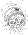
- Figure 7 shows a perspective view of another embodiment of a connector 10.
- the connector 10 shown in Fig. 7 may comprise similar and/or the same components as the connector 10 described with respect to Figs. 1-3 . Therefore, the same or similar reference signs are used when describing this embodiment of the connector 10.
- the connector 10 shown in Fig. 7 may be formed as a circular connector, in particular provided as (at least part of) a vehicle and/or truck connector.
- the connector 10 substantially extends from a cable end 13 to a connecting end 14 in the connection direction C.
- the connection direction C is a direction in which an electric plug-connection may be established between the connector 10 and a corresponding connector and/or the extension adapter shown in Figs. 9-10 .
- Figure 8 shows a cross-sectional view of the connector 10 shown in Fig. 7 .
- the ethernet cable 20' with its ethernet cable end portion 20 is omitted in Figs. 7 and 8 .
- the connector 10 shown in Figs. 7 and 8 is connected to an ethernet cable 20'. This applies in particular to its extension contacts 70a, 70b and its connector shieldings 30a, 30b.
- the connector 10 shown in Figs. 7 and 8 may comprise the connector housing 40 with the first connector housing component 41 and the second connector housing component 42. It may comprise the outer isolator 50 with the first holding portion 54a and the second holding portion 54ab and the outer isolator components 51, 52 (cf. also Fig. 7 ). It may also comprise the first inner isolator 60a (comprising, e.g., the first inner isolator component 61a and the second inner isolator component 62a) holding the first extension contacts 70a.
- It may comprise the second inner isolator 60b (comprising, e.g., the first inner isolator component 61b and the second inner isolator component 62b) holding the second extension contacts 70b. It may comprise the first connector shielding 30a holding the first inner isolator 60a which is holding the first extension contacts 70a. And it may comprise the second connector shielding 30b holding the second inner isolator 60b which is holding the second extension contacts 70b.
- the first connector housing component 41 may comprise the connection opening 12 at the connecting end 14 of the connector housing 40.
- the second connector housing component 42 may comprise the cable opening 11 at the cable end 13 of the connector housing 40.
- the first and second connector housing components 41,42 are statically fixed to each other, thereby forming the connector housing 40 of the connector 10. They may, e.g., be screwed and/or clipsed to each other.
- the first connector housing component 41 is configured to receive and/or hold a mating connector (not shown) for establishing an ethernet connection through and/or at the connection opening 12.
- the connector housing 40 and/or the first connector housing element 41 may be configured to indirectly receive and/or hold the (not shown) mating connector.
- indirectly may mean that it does not directly contact the mating connector, but that at least one other component is plugged in between.
- This other component may be provided as the extension adapter 90 shown in Figs. 9-10 .
- the connector 10 is first extended by the extension adapter 90, and then plugged into the mating connector. It may be plugged directly and/or indirectly into said mating connector.
- the mating connector may first be extended by a similar extension adapter, so that the two extension adapters 90 are connected to each other, e.g., by a plug connection.
- the first connector shielding 30a comprises a plurality of connector shielding protrusions 38a.
- One or more of the connector shielding protrusions 38a may protrude from the first connector shielding member 31a in connection direction C.
- One or more of the connector shielding protrusions 38a may protrude from the second connector shielding member 32a in connection direction C.
- the second connector shielding 30b comprises a plurality of connector shielding protrusions 38b.
- One or more of the connector shielding protrusions 38b may protrude from the first connector shielding member 31b in connection direction C.
- One or more of the connector shielding protrusions 38b may protrude from the second connector shielding member 32b in connection direction C.
- the at least one separator 53 of the outer isolator 50 separates the first connector shielding 30a and the second connector shielding 30b.
- the connector housing 40 comprises at least one protrusion 82.
- the connector housing 40 comprises two protrusions 82 extending from the connecting end 14 in connection direction C.
- a shape of the protrusion 82 may follow the outer shape of the (here: circular) housing 40.
- inner section of the protrusion 82 may be shaped concave, and/or an outer section of the protrusion 82 may be formed convex.
- the protrusion 82 may span over from about 3% to about 20%, in particular from about 5% to about 15%, of the outer shape of the connector housing 40, e.g., over from about 10° to about 75° of the circular outer shape of the connector housing 40.
- each protrusion 82 may provide a substantial stabilisation function between the connector 10 and the extension adapter 90.
- Two protrusions 82 may be provided at opposite sides of the connection opening 12. This may provide an improved stabilization and/or fixation between the connector 10 and the extension adapter 90.
- the connector 10 may comprise a connection thread 84, e.g., at the connection end 14 of the connector 10.
- the connection thread 84 may be provided as an outer thread at an outer section of the connector housing 40.
- the connection thread 84 may be used to establish a secure and/or releasable screwing connection between the connector 10 and the extension adapter 90.
- Figure 9A shows a perspective view of an embodiment of an assembled extension adapter 90 when looking at an adapter connecting end 99b of the extension adapter 90.
- Figure 9B shows a perspective view of the extension adapter 90 when looking at a connector end 99a of the extension adapter 90.
- the extension adapter 90 comprises an adapter housing 91 extending substantially from the connector end 99a to the adapter connecting end 99b.
- the extension adapter 90 is configured as an extension of the connector 10. As such, it may comprise similar components as the connector 10 that extend the components of the connector 10. For these components of the extension adapter 90 being similar to the components of the connector 10, the above description applies equally.
- the extension adapter 90 comprises the adapter housing 91 being configured similar to the housing 40 of the connector 10.
- the adapter housing 91 comprises and/or holds and/or surrounds a plurality of components of the extension adapter 90.
- the extension adapter 90 may comprise at least some or all of the following components:
- the adapter housing 91 of the extension adapter 90 extends and may have similar functions as the housing 40 of the connector 10.
- the outer adapter isolator 92 of the extension adapter 90 extends and may have similar functions as the outer isolator 50 of the connector 10.
- the first adapter shielding 96a of the extension adapter 90 extends and may have similar functions as the first connector shielding 30a of the connector 10. Indeed, the first adapter shielding 96a may be electrically coupled to the first connector shielding 30a so that they share the electrical potential.
- the second adapter shielding 96b of the extension adapter 90 extends and may have similar functions as the second connector shielding 30b of the connector 10.
- the second adapter shielding 96b may be electrically coupled to the second connector shielding 30b so that they share the electrical potential.
- the first inner adapter isolator 94a of the extension adapter 90 extends and may have similar functions as the first inner isolator 60a of the connector 10.
- the second inner adapter isolator 94b of the extension adapter 90 extends and may have similar functions as the first inner isolator 60b of the connector 10.
- the two first adapter contacts 95a, 95b may be electrically coupled to the two first extension contacts 70a, respectively, so that they may conduct signals from the two first ending contacts 24a of the first twisted pair 22a (cf. Fig. 2 ).
- the two second adapter contacts 95c, 95d may be electrically coupled to the two second extension contacts 70b, respectively, so that they may conduct signals from the two second ending contacts 24b of the second twisted pair 22b (cf. Fig. 2 ).
- the extension adapter 90 is fixed to the connector 10 so that it may be considered as a component of the connector 10. Then, the connector end 99a of the extension adapter 90 is facing the connecting end 14 of the connector 10 and the adapter connecting end 99b provides an end opposite the ethernet cable 20 for being connected by a mating connector.
- all adapter contacts 95a-d are configured as male adapter contacts.
- the connector 10 (including the extension adapter 90) is configured as connector comprising only male contacts.
- the adapter contacts may all be configured as female contacts, or any mix of male and female contacts.
- the outer adapter isolator 92 and/or the inner adapter isolators 94a, 94b may comprise and/or consist of two or more inner/outer isolator components.
- the two adapter shielings 96a, 96b of the extension adapter 90 may comprise and/or consists of two or more adapter shielding components.
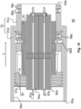
- Figure 10 shows a cross-sectional view of the extension adapter 90 of Figures 9A and 9B .
- the adapter housing 91 may comprise a first adapter housing component 91a at the adapter connecting end 99b and a second adapter housing component 91b at the connector end 99a.
- the two adapter housing components 91a, 91b may be connected via connecting means, e.g., an adapter ring 98d configured as a clamping ring.
- a second adapter seal 98b may seal a connection between the two adapter housing components 91a, 91b from fluids and/or dirt.
- the adapter contacts 95a-d may extend throughout the whole extension adapter 90.
- they protrude from their respective inner adapter isolator (in Fig. 10 : the first inner adapter isolator 94a) as either male or female contacts. In the shown embodiment, they extend as male contacts.
- they are configured to electrically couple to the extension contacts 70a, 70b of the connector 10 (cf. Fig. 8 ).
- the extension adapter 90 may comprise an inner adapter thread 97a and/or at least one adapter recess 97 at its connector end 99a.
- the protrusion(s) 82 of the connector 10 (cf. Figs. 7-8 ) may be inserted into the adapter recess(es) 97 of the extension adapter 90.
- the adapter thread 97a may be screwed to the connection thread 84 of the connector 10 (cf. Figs. 7-8 ).
- the connector shielding protrusion(s) 38a, 38b may be pressed onto the adapter shielding(s) 96a, 96b, respectively, to establish an electrical connection.
- connection between the connector 10 and the extension adapter 90 may be protected from fluids and/or dirt by a connector seal 85 (cf. Fig. 8 ). Additionally, it may be statically improved by an adapter collar 98e of the extension adapter 90 into which the housing 40 of the connector 10 is at least partially inserted during assembly. Alternatively, the collar and/or the seal may be provided at the respective other component, so that at least one of the connector 10 and/or the extension adapter 90 may comprise a seal and/or a collar to improve the connection.
- the extension adapter 90 is, thus, mounted to the adapter receptable 80 of the connector 10 so that its contacts are configured as provided by the extension adapter 90 (in the shown embodiment: as male contacts).
- the extension adapter 90 is removably mounted and/or fixed to the connector 10, so that it may be exchanged, e.g., whenever it is damaged. It may also be exchanged in case other types of contacts are desired.
- the connector 10 is highly configurable, so that any customer may choose the kinds of contacts he requires and/or desires.
- the extension adapter 90 may comprise a first adapter seal 98a held in a groove and/or by an adapter bulge 98c.
- the first adapter seal may protect the connection between the extension adapter 90 and the mating connector from fluids and/or dirt.
- Each or any of the seals 85, 98a, 98b may be provided as an O-ring.
Landscapes
- Details Of Connecting Devices For Male And Female Coupling (AREA)
Abstract
A connector (10; 10a; 10b) for establishing an ethernet connection comprises a connector housing (40) and an ethernet cable end portion (20) entering the connector housing (40) at a cable end (13) of the connector (10) and comprising at least one twisted pair (22a; 22b; 22c; 22d) with two ending contacts (24a; 24b). At least one adapter receptacle (80) is provided at a connecting end (14) of the connector (10; 10a; 10b). Therein, each ending contact (24a; 24b) is electrically connected to an adapter contact (95a-d) and removably attached to the adapter receptacle (80).
Description
- The invention relates to a connector for establishing an ethernet connection, a superconnector, and a method of assembling a connector.
- Ethernet connection cables and connectors may be used in various environments and/or networks for establishing ethernet connections. Examples of such environments may be facilities such as factories and/or offices. However, ethernet connections may also be established within transport vehicles such as cars and/or trucks. Ethernet connection cables used in such environments may comprise eight wires which can be arranged in four twisted pairs, wherein each twisted pair comprises two wires of said eight wires arranged in a twisted form.
- Especially for trucks, there exist a plurality of components that need to be connected to the ethernet and/or the cab of the truck, in particular different kinds of trailers. Depending on the circumstances, some truck connectors are better configured with male and some with female contacts.
- A problem in ethernet connectors for vehicles may be caused by physical strain on the connector and/or the ethernet cable caused by, e.g., driving movements and/or extreme weather. Said strain may impact on both the electrical and/or the shielding contact between the connector and the ethernet cable.
- Accordingly, it is an object of the claimed invention to provide a versatile connector for establishing an ethernet connection. In particular, it may be an object to provide a connector for establishing an ethernet connection within vehicles which is less susceptible to damage.
- This object is solved by the subject-matter of the independent claims. Preferred embodiments are subject of the dependent claims.
- An aspect relates to a connector for establishing an ethernet connection comprising a connector housing. The connector comprises an ethernet cable end portion entering the connector housing at a cable end of the connector and comprising at least one twisted pair with two ending contacts. At least one adapter receptacle is provided at a connecting end of the connector. Therein, each ending contact is electrically connected to an adapter contact and removably attached to the adapter receptacle.
- The connector may be formed as a circular connector and is configured to establish at least part of a full ethernet connection. The connector may be configured to establish additional electric contacts not associated to an ethernet connection, e.g., contacts for communicating vehicle signals, e.g., signals for breaking lights etc.
- The connector may be formed as a plug connector and/or a socket connector. The connector housing may comprise a connection opening and/or a cable opening. The connection opening may be formed at a side of the connector, where the connector is configured to directly or indirectly engage with a mating connector for establishing an ethernet connection. This side and/or end of the connector may be provided as the connecting end of the connector. For example, the connector can be formed as a socket connector comprising the connection opening in which a mating plug connector may be inserted such that said two connectors engage and establish electric contact.
- The cable opening may be formed at a side of the connector wherein the ethernet cable end portion can be at least partially arranged, in particular held, within the cable opening such that the ending contacts are arranged inside of the connector housing. This side and/or end of the connector is provided as the cable end of the connector. In embodiments wherein the connector is provided as a straight connector, it may be arranged at an end opposite the connecting end. Each ending contact may configured and/or held within the connector such that the ending contacts electrically contact mating ending contacts of a mating connector.
- The ethernet cable end portion may be provided as an end section of an ethernet cable. The ethernet cable may be provided as a cable configured to establish at least part of an ethernet connection. The ethernet cable end portion may comprise, e.g., one, two, three, or four twisted pairs. For ethernet cable end portions comprising only one, two, or three twisted pairs, the twisted pairs of the ethernet cable end portion may not suffice to establish a full ethernet connection. However, e.g., two ethernet cables, each comprising, e.g., two twisted pairs, may be combined to provide an ethernet connection cable comprising the usual four twisted pairs. For example, the connector may comprise two such ethernet cable end portions. Alternatively, two connectors may be used to establish a full ethernet connection, each of which comprising one of the two ethernet cable end portions with only two twisted pairs, respectively.
- The twisted pair may comprise two conducting wires at least partially twisted around each other, each of the wires being encased in an isolator, respectively. The ethernet cable end portion comprises at least one such twisted pair. The twisted pair may be shielded by an associated pair shielding. The pair shielding may be provided as a sleeve around its associated twisted pair. The pair shielding may be provided as integral component of the ethernet cable which's end is comprised in the connector.
- In embodiments wherein the ethernet cable end portion comprises a plurality of twisted pairs, each twisted pair may be shielded by an associated pair shielding, respectively.
- The ending contacts of the twisted pair may be provided as ending portions of the wires of the twisted pair. Each ending contact may be arranged inside of the connector, and it may be at least partially stripped from its isolator.
- The term "contacting" and variants thereof may describe a state in which at least two objects are in physical and/or electronical contact. In particular, they may be in direct physical contact. Thus, there may be a direct contact between the at least two, in particular conductive and/or magnetic, objects enabling a conductive connection between the at least two objects.
- An electrical contact may be established without direct physical contact, but by a merely indirect contact. For example, the ending contacts do not have to be in direct physical contact with the adapter contacts. Instead, the ending contacts may be in physical contact with extension pins and/or extension contacts, and these may be in direct contact with the adapter contacts. Thus, each ending contact is electrically coupled to its associated adapter contact via the associated extension contact.
- The connector may comprise at least one connector shielding. The connector shielding may be arranged at least partially and/or substantially fully within the connector housing. It may house an associated inner isolator and the ending contacts of an associated twisted pair. The connector shielding may be configured to provide a shielding function to the ending contacts and their optional extensions (like extension contacts and/or extension pins) within the connector. Optionally, it may also be configured to shield the adapter contacts associated to the ending contacts it shields.
- The connector shielding (including its components) may be provided as stamping component.
- The associated ending contacts of at least one of the twisted pairs are arranged so that the connector shielding may at least partially enclose the ending contacts arranged therein.
- The optional inner isolator may be arranged within the optional connector shielding and between the connector shielding and the ending contacts. The inner isolator may prevent the ending contacts form contacting the connector shielding and/or each other. The inner isolator may be snuggly fit into the connector shielding. It may be provided from an isolating material, e.g., from a suitable plastic and/or ceramic. The inner isolator may be provided as an injection moulded part.
- The connector comprises the adapter receptacle which is configured to removably receive and/or hold the adapter contacts.
- The adapter receptacle may be designed as individual adapter receptacle, wherein the individual adapter receptacle is configured to receive and/or hold exactly one adapter contact. In this embodiment, the connector may comprise a plurality of individual adapter receptacles, e.g., one individual adapter receptacle for each ending contact.
- Alternatively, the adapter receptacle may be designed as group adapter receptacle, wherein the group adapter receptacle is configured to receive and/or hold a plurality of adapter contacts, e.g., the two ending contacts of one of the twisted pairs. In this embodiment, the connector may comprise only a single group adapter receptacle for all adapter contacts, a so-called total adapter receptacle. Or it may comprise a plurality of group adapter receptacles, e.g., one group adapter receptacle for the two ending contacts of each twisted pair, so-called pair adapter receptacles. One example of a group adapter receptacle is a double pair adapter receptacle. Therein, the double pair adapter receptacle is configured to receive and/or hold four adapter contacts for the four ending contacts of two twisted pairs, i.e., the adapter contacts for half a regular ethernet cable.
- Whether the adapter receptacle is provided as individual, group, total, double pair, and/or pair adapter receptacle, each adapter receptacle is configured so that at least one of the adapter contacts may be removably assembled to the respective adapter receptacle.
- Each adapter contact is provided from an electrically conductive material, e.g., from metal. Each individual adapter contact is electrically coupled and connected to its associated individual ending contact of one wire of any of the twisted pairs entering the connecter through the cable opening. Each adapter contact may be configured as a male or female adapter contact. Each adapter contact is configured to be contacted by a mating contact, e.g., a mating adapter contact, of a mating connector. Whenever the adapter contacts are in contact with such mating contacts of the mating connector, an electrical contact to the wires of the twisted pair is established, e.g., as at least part of an ethernet connection. For this, the adapter contacts may be arranged so that they are accessible from the connection end and/or through the connecting opening of the connector.
- The adapter receptacle and/or the adapter contacts is/are configured to stay attached and assembled during normal plugging and unplugging action of the connector. In other words, the adapter receptacle and/or the adapter contacts is/are configured to withstand normal operation of the connector when establishing and interrupting an electrical connection. This may be achieved by fixing the at least one adapter contact sufficiently strong to the adapter receptacle.
- The at least one adapter contact may be assembled to the adapter receptacle by a force fit and/or by a from-fit in, e.g., by a screwing connection and/or a clip connection.
- However, even though the at least one adapter contact is, thus, fixed and assembled at the connector, it may be removed from the connector without destroying the connector. For example, it may be screwed out of the adapter receptacle and, thus, removed.
- After removal, the adapter contact may be disposed and/or exchanged for a new and/or different adapter contact. In particular in vehicles, serious strain may affect the electrical connections, e.g., connecting a cab of a truck to a trailer. This strain may, in particular, affect the adapter contacts of the connector. Thus, the adapter contacts may get damaged from wear and/or use. After the adapter contacts are damaged, the connector does not have to be exchanged as a whole. Instead, only the damaged adapter contacts may get exchanged and new (or repaired) adapter contacts may be attached to the connector. This may reduce waste, because in most cases, only the damaged adapter contacts need to be replaced. Furthermore, it may simplify a repair, because not the whole connector (including the, e.g., moulded ethernet cable end portion) need to be disposed of and/or rewired, but merely the adapter contacts need to be replaced. Thus, it may also render repairs less cost intensive.
- The connector may further comprise an outer connector shielding, and the ethernet cable end portion may further comprise an outer cable shielding. The outer connector shielding can at least partially enclose the connector shielding. It can be arranged within the connector housing and out of contact, in particular out of physical and/or electrical contact, from the connector shielding.
- The outer cable shielding can at least partially enclose the pair shielding of the ethernet cable end portion and/or it can be arranged within the ethernet cable end portion and out of contact, in particular out of physical and/or electrical contact, from the pair shielding of the at least two twisted pairs. Thereby, the twisted pair and the ending contacts can be additionally shielded from electromagnetic interference.
- The outer connector shielding and the outer cable shielding may contact each other to enable sharing a common electrical potential. This may enable a continuous shielding of the twisted pair within the ethernet cable end portion and the ending contacts within the connector housing.
- The connector may be provided as and/or comprised in a vehicle connector, wherein the vehicle connector is a connector for establishing at least an ethernet connection between at least two modules or components of a vehicle. For example, the vehicle can be any one of a car, a bus, and a truck. For example, the vehicle connector can be used for establishing at least part of an ethernet connection between a computer inside of an operator cabin of the vehicle and a system of an attached trailer of the truck. The connector may enable data transfer between the at least two modules or components of the vehicle.
- The connector may be configured to only contribute to establishing an ethernet connection, e.g., in embodiments wherein the connector comprises only one, two, or three twisted pairs in the ethernet cable end portion. In embodiments wherein the connector comprises two twisted pairs in the ethernet cable end portion, the connector may establish half of an ethernet connection. Two such connectors used in combination may establish a full ethernet connection comprising the usual four twisted pairs.
- The connector comprising two twisted pairs may be configured to connect with a corresponding connector comprising also two twisted pairs and/or a corresponding portion of a connector comprising four twisted pairs. The use of connectors comprising less than four twisted pairs may allow a greater distance between the different connectors for a full ethernet connection, thereby providing improved design options.
- The connector may be provided for signalling according to the Cat 8a and/or Cat9a Standard.
- The connector may be formed as a transformable connector, wherein the transformable connector is configured to releasably engage with different kinds of adapter contacts. Thus, the transformable connector may, e.g., be at least partially transformed into a plug and/or socket connector. Then, each ending contact of the connector may contact either a plug element or a socket element. The connector may comprise male and/or female adapter contacts. In particular, the connector may be provided as a truck connector for establishing a connection within a truck and/or vehicle.
- In an embodiment, each adapter contact is individually exchangeable attached to the adapter receptacle. Herein, every single adapter contact of the connector may be removed individually from the adapter receptacle. Thus, it may be traded and or exchanged with a new and/or repaired adapter contact. In this embodiment, even when only a single adapter contact is damaged, it may be individually substituted and/or replaced. This may reduce waste and/or repair costs even further.
- In an embodiment, the connector comprises at least one extension adapter holding one, some or all of the adapter contacts. Therein, the extension adapter is removably attached to the adapter receptacle so that each adapter contact is electrically connected to an associated ending contact. The extension adapter may be configured similar to the connector itself. For example, the extension adapter may comprise one or more of the following: an adapter housing, an outer adapter isolator, an adapter shielding, an inner adapter isolator, and/or at least one adapter contact. The extension adapter may be configured as an extension of the connector extending the connector at its connection end in connection direction. The extension adapter may comprise a connector end provided at an end facing the connector and/or an adapter connecting end at an end configured to directly or indirectly engage with a mating connector for establishing an ethernet connection. The extension connector may substantially extend from the connector end to the adapter connecting end. At the connector end, the extension adapter is configured to engage with the connecting end of the connector, e.g., with the adapter receptacle. For example, a plug connection may be established between the extension adapter and the connector so that each adapter contact of the extension adapter is electrically connected to its associated ending contact of the twisted pair(s). The extension adapter may enable a simple assembly of the adapter contact(s) at the adapter receptacle, in particular when a plurality (in particular: all) of the adapter contacts are comprised in the extension adapter. The extension adapter may provide an isolating and/or shielding function for the adapter contact(s). The extension adapter may provide a physical protection to the adapter contact(s) by holding them securely and/or statically fixed within an adapter housing. At the adapter connecting end, the extension adapter may provide a connecting function, e.g., similar to a plug and/or socket connection.
- Similar as the adapter receptacle, also the extension adapter may be designed as group extension adapter, wherein the group extension adapter is configured to hold a plurality of adapter contacts, e.g., the two ending contacts of one of the twisted pairs. In this embodiment, the connector may comprise only a single group extension adapter for all adapter contacts, a so-called total extension adapter. Or it may comprise a plurality of group extension adapters, e.g., one group extension adapter for the two ending contacts of each twisted pair, so-called pair extension adapters. One example of a group extension adapter is a double pair extension adapter. Therein, the double pair extension adapter is configured to hold four adapter contacts for the four ending contacts of two twisted pairs, i.e., the adapter contacts for half a regular ethernet cable.
- According to a development of the embodiment, at least two adapter contacts are provided in the extension adapter. The extension adapter is removably inserted in the adapter receptacle. The extension adapter may comprise fixing means for fixing the extension adapter to the adapter receptacle. In this embodiment, not the individual adapter contacts are removably attached to the adapter receptacle, but they are first provided in the at least one extension adapter. Then this extension adapter is removably attached to the adapter receptacle. Herein, the adapter contacts may be removed together with the extension adapter from the adapter receptacle whenever there is a need to exchange them either for repair or for individual configuration. The shape of the extension adapter, in particular its outer shape, may be configured to match an inner shape of the adapter receptacle. The extension adapter may be configured to stay attached to the connector during normal operation of the connector, e.g., during plugging and/or unplugging operation. The may be fixed to the connector in a form fit and/or a force fit. Grouping more than one adapter contact together in the at least one extension adapter may enable a faster removal of all adapter contacts from the connector than removing them individually. This may render assembling the connector faster.
- According to a development of the embodiment, the extension adapter comprises at least two adapter shieldings, each adapter shielding being associated to a dedicated twisted pair of the cable end portion. Therein, each adapter shielding encloses two of the adapter contacts associated to the ending contacts of the twisted pairs associated to the respective adapter shielding. The adapter shieldings are arranged separately and out of contact from each other within the extension adapter. An individual shieling of the two adapter contacts associated to the ending contacts of a twisted pair may improve the overall shielding quality and/or the data transfer along the twisted pair. This may improve the possible overall data transfer rate along the ethernet connection.
- According to an embodiment, every adapter contact of the connector is selectively configured as male or female adapter contact. Herein, every single adapter contact may be selectively configured as male or female adapter contact. In other words, the adapter receptacle is configured to receive and/or hold at each designated position either a female adapter contact or a male adapter contact. Thus, a buyer of the connector may individually choose at which position he prefers a male contact, and at which position he prefers a female contact within the connector. This enables an individual design for the connector. This may enable a versatile connector adapted to a plurality of different fields of application.
- According to an embodiment, the ethernet cable end portion comprises at least a first twisted pair with two first ending contacts and a second twisted pair with two second ending contacts. Each of the two first ending contacts is electrically connected to an associated first adapter contact, respectively. Each of the two second ending contacts is electrically connected to an associated second adapter contact, respectively. Each of the first and second adapter contacts is removably attached to the adapter receptacle. In this embodiment, the connector is configured to establish an electrical connection for at least two twisted pairs of the ethernet cable and portion. Every single wire of these at least two twisted pairs is electrically connected to its own associated adapter contact. The connector may also comprise individually dedicated adapter contacts for all eight wires of all four pay pairs of an ethernet connection cable. The more adapter contacts the connector comprises, the more versatile it becomes.
- According to a further development of this embodiment, each of the first and second adapter contacts are provided in the extension adapter. Thus, they may be assembled and/or removed and exchanged together as a group. This may enable an easy individual configuration of the adapter contacts and/or an easy repair in case one or all of the adapter contacts are damaged. Herein, the extension adapter is associated to the first and second twisted pair and their four ending contacts. Thus, the two first and the two second adapter contacts may be configured and/or removed together for the first and second twisted pair. Therein, the first and second adapter contacts may be individually configured as male or female adapter contacts. Grouping at least four adapter contacts together in a common extension adapter (e.g., a double pair extension adapter) may render configuring the connector simple and/or fast.
- According to an embodiment, the adapter receptacle is provided as a recess within the connector housing. The adapter contacts may be inserted in said recess. They may also be removably fixed and/or attached in said recess. The recess may improve holding and/or arranging the adapter contacts in a predetermined position and/or arrangement direction.
- According to an embodiment, the adapter receptacle comprises at least one adapter groove for the removable attachment of the adapter contacts and/or the extension adapter. The adapter groove may be arranged and/or provided substantially parallel to a connection direction of the connector. Generally, the connection direction may be provided as direction from the cable and to the connecting end of the connector. Arranging the adapter groove substantially parallel to the connection direction may render inserting the adapter receptacle is simple. The adapter groove may receive the adapter contact and/or the extension adapter it is provided in. It may further provide an arrangement function for aligning the adapter contact in its designated assembling position. The adapter groove may be provided as an inner adapter groove in the connector housing.
- According to an embodiment, the adapter receptacle comprises at least one protrusion and/or a connection thread and/or latching element for the removable attachment of the adapter contacts and/or the extension adapter. The latching element may be provided as an elastic hook and/or protrusion enabling a collapsing connection between the adapter receptacle and the adapter contacts and/or the according extension adapter. The at least one protrusion may extend substantially in connection direction at the connecting end of the connector. It may be configured to extend into an adapter recess of the extension adapter. The adapter recess may be provided at the connector end of the extension adapter. The protrusion and/or the connection thread and/or the latching element may be provided in the adapter receptacle. Alternatively or additionally, a protrusion and/or a thread and/or a latching element may be provided at the adapter contact and/or the extension adapter. The protrusion and/or the connection thread and/or the latching element may provide a reliable and removable connection between the adapter contact and/or the extension adapter one a first side and the adapter receptacle on a second side.
- According to an embodiment, the connector comprises at least two connector shieldings, each connector shielding being associated to a dedicated twisted pair of the cable and portion. Therein, each connector shielding encloses the ending contacts of the associated twisted pair. The connector shieldings are arranged separately and out of contact from each other within the connector housing. Herein, the ending contacts of each twisted pair are shielded separately and/or individually by their dedicated and/or associated connector shielding within the connector. Such an individual shielding of the ending contacts of each twisted pair may improve the signalling quality along the ethernet connection. It may reduce noise and/or currents induced within the connector shieldings. Thus, it may improve overall signalling quality.
- According to a development, each adapter shielding is electrically and/or conductively connected to an associated connector shielding. Therein, the adapter shieldings and the connector shielding are associated to the ending contacts of a single twisted pair. Thus, the ending contacts of each twisted pair may be shielding individually and continuously throughout both the connector and the extension adapter. Such an individual shielding of the ending contacts of each twisted pair throughout the whole connector (including the extension adapter) may improve the signalling quality along the ethernet connection. It may reduce noise and/or currents induced within the connector shieldings. Thus, it may improve overall signalling quality.
- An aspect relates to a superconnector for establishing an ethernet connection comprising a superhousing in which two connectors according to the previous aspect are arranged. An ethernet connection cable end portion comprises four twisted pairs apportioned to the two ethernet cable end portions of the two connectors.
- The ethernet connection cable end portion may be provided as an end of an ethernet connection cable comprising eight wires. The four twisted pairs of the ethernet connection cable end portion are split up into two ethernet cable end portions, each of which comprising two twisted pairs, respectively. Thus, each of the two connectors comprises its respective ethernet cable end portion with two twisted pairs each.
- Each wire of the four twisted pairs may be electrically contacted by an associated adapter contact, respectively. Each of the adapter contacts may be designed as described in the above aspect. Therefore, the above description also relates to this aspect and vice versa.
- The superconnector can further comprise an outer superconnector shielding, and the ethernet connection cable end portion can further comprise an outer connection cable shielding. The outer superconnector shielding can at least partially enclose ending contacts and/or the adapter contacts.
- The superconnector may comprise additional connection wires.
- In an embodiment, the superconnector is be provided as a truck connector configured to establish an ethernet connection within a truck, e.g., between the cab and a trailer. It may comprise the regular truck connection wires arranged at the regular truck connector positions and, additionally, the two additional connectors for providing the ethernet connection. Herein, the two connectors may be integrated within a standard connector like the truck connector, thereby forming the superconnector.
- A further aspect relates to a connector system comprising two connectors, e.g., a plugand-socket-system, comprising a first connector according to the above aspect and a second connector according to the above aspect configured to engage each other. The connectors can be formed according to any one of the embodiments of the above aspects.
- An aspect relates to a method for assembling a connector for establishing an ethernet connection comprising the steps:
- providing a connector housing;
- arranging an ethernet cable end portion so that it enters the connector housing at a cable end of the connector, wherein the ethernet cable end portion comprises at least one twisted pair with two ending contacts;
- providing an adapter receptacle at a connecting end of the connector; and
- removably attaching adapter contacts to the adapter receptacle so that each ending contact is electrically connected to one of the adapter contacts.
- The method may be used for assembling the connector according to the above aspect. Therefore, the description of the above aspect also relates to the method and vice versa.
- The method may comprise a step of selecting which adapter contact should be provided as male adapter contact and which adapter contact should be provided as female adapter contact. Herein, each adapter contacts may be individually configured and selected as either male or female adapter contact, and the adapter contacts are removably attached accordingly.
- Herein, the terms upper, lower, below, above, etc. refer to the reference system of the Earth in a mounting position of the subject-matter.
- The numbers and/or angles given in the claims and the description are not limited to the exact numbers and/or angles, but may include measurement inaccuracies within limits that still enable solving the underlying problem.
- The invention is further illustrated in reference to embodiments shown in the figures. Embodiments of the invention are described with reference to the figures. Features of the embodiments shown in the figures may be combined with other embodiments. Identical reference numbers may identify identical or similar features of the embodiments.
- Figure 1
- shows a drawing of a cross-sectional view of an embodiment of an assembled connector.
- Figure 2
- shows an exploded view of some parts of the connector of
Figure 1 . - Figure 3
- shows a front view of the connector of
Figure 1 in an assembled form. - Figure 4
- shows a spatial front view of most parts of the connector of
Figure 1 in an assembled form. - Figure 5
- shows a spatial view of the connector of
Figure 1 in an assembled form. - Figure 6
- shows a schematic drawing of a cross-sectional view of an embodiment of two superconnectors, each comprising two connectors.
- Figure 7
- shows a perspective view of another embodiment of an assembled connector.
- Figure 8
- shows a cross-sectional view of the connector of
Figure 7 . - Figure 9A
- shows a perspective view of an embodiment of an assembled extension adapter when looking at an adapter connecting end of it.
- Figure 9B
- shows a perspective view of the extension adapter of
Figure 9A when looking at a connector end of it. - Figure 10
- shows a cross-sectional view of the extension adapter of
Figures 9A and9B . -
Figure 1 shows a cross-sectional view of an embodiment of aconnector 10, formed as a circular connector, in particular provided as (at least part of) a vehicle and/or truck connector. A dashed line inFigure 3 (showing thesame connector 10 from another direction) indicates the location of the cross-section shown inFigure 1 . The cross-section is arranged parallel to a connection direction C of theconnector 10. - The
connector 10 substantially extends from acable end 13 to a connectingend 14 in the connection direction C (corresponding to the z-direction in the figures and indicated by the arrow C inFigures 1 ,2 ,4 , and5 ). - The connection direction C is a direction in which an electric plug-connection may be established between the
connector 10 and a corresponding connector. - The
connector 10 comprises an ethernet cable end portion 20 which can be an end portion of an ethernet cable 20'. In the shown embodiment, at least the ethernet cable end portion 20 extends in connection direction C. Ethernet data signals may be communicated along the ethernet cable end portion 20. Aconnector housing 40 comprises a substantially cylindrical form and may be provided as an outer hull of theconnector 10. Inside of theconnector housing 40, anouter isolator 50 is arranged physically contacting theconnector housing 40 from inside. Inside of theouter isolator 50, a first connector shielding 30a is arranged (together with a second connector shielding 30b not shown inFig. 1 but, e.g., inFig. 3 ). Inside of the first connector shielding 30a, a firstinner isolator 60a is arranged holdingfirst extension contacts 70a. Similarly, a secondinner isolator 60b holdingsecond extension contacts 70b is arranged within the second connector shielding 30b (not shown inFig. 1 ). - The ethernet cable end portion 20 comprises a first
twisted pair 22a with twofirst wires 23a, wherein eachfirst wire 23a comprises onefirst ending contact 24a. Although thefirst wires 23a are depicted in a non-twisted form inFig. 1 , thefirst wires 23a can be at least partially twisted around each other. Thefirst wires 23a may be isolated, respectively, except at thefirst ending contacts 24a. Thefirst wires 23a are partially enclosed by a first pair shielding 26a. The first pair shielding 26a may be provided from a foil, a mylar, and/or a mesh. Thefirst ending contacts 24a and an adjacent portion of thefirst wires 23a are not enclosed by the first pair shielding 26a. The first pair shielding 26a may be stripped from this section of thefirst wires 23a. - At least the
first ending contacts 24a and the stripped section of thefirst wires 23a (not enclosed by the first pair shielding 26a) are arranged inside theconnector housing 40 of theconnector 10. Additionally, also a section of thefirst wires 23a which is enclosed by the first pair shielding 26a may be arranged within theconnector 10. - The
connector housing 40 may have a substantially cylindrical form. It may comprise and/or consist of a (e.g., substantially cylindrical) firstconnector housing component 41 and a (e.g., substantially cylindrical) secondconnector housing component 42. The firstconnector housing component 41 comprises aconnection opening 12 at the connectingend 14 of theconnector housing 40. The secondconnector housing component 42 comprises a cable opening 11 at thecable end 13 of theconnector housing 40. - The first and second
connector housing components connector housing 40 of theconnector 10. They may, e.g., be screwed and/or clipsed to each other. - The first
connector housing component 41 is configured to receive and/or hold a corresponding connector (not shown) for establishing an ethernet connection through and/or at theconnection opening 12. - The ethernet cable end portion 20 enters the
connector 10 through the cable opening 11, such that thefirst ending contacts 24a are arranged inside of theconnector housing 40 between the cable opening 11 and theconnection opening 12. Thefirst ending contacts 24a as well as the ethernet cable end portion 20 are arranged so that they point towards theconnection opening 12, which is the connection direction C of theconnector 10. Accordingly, a direction from the cable opening 11 towards theconnection opening 12 is the connection direction C of theconnector 10. - One
first extension contact 70a may be attached to each of the twofirst ending contacts 24a, respectively, further extending into the pointing direction of thefirst ending contacts 24a towards the connectingend 14. Thefirst ending contacts 24a and thefirst extension contacts 70a are arranged in recesses of and held by the firstinner isolator 60a. The firstinner isolator 60a may comprises and/or consists of a firstinner isolator component 61a and a secondinner isolator component 62a, each of which partially comprises the recesses, such that thefirst ending contacts 24a and thefirst extension contacts 70a are arranged between and/or held by the firstinner isolator component 61a and the secondinner isolator component 62a. At an end of thefirst extension contacts 70a facing the connecting end 14a, the firstinner isolator 60a comprises an opening for eachfirst extension contact 70a, such that thefirst extension contacts 70a may establish an electrical connection in the connection direction C. - The first
inner isolator 60a may be enclosed by the first connector shielding 30a. Thereby, the first connector shielding 30a may fully enclose thefirst ending contacts 24a and/or thefirst extension contacts 70a in a direction radial to the connection direction C of theconnector 10. - The first connector shielding 30a is electrically isolated by the first
inner isolator 60a from the inside and by theouter isolator 50 from the outside. It may be held between those twoisolators - The first connector shielding 30a may comprises and/or consist of a first
connector shielding member 31a and a (e.g., substantially identical) secondconnector shielding member 32a (not shown inFig. 1 ) contacting each other. At aconnection end 36a of the first connector shielding 30a, which is provided as an end facing the connectingend 14, i.e., in connection direction C of theconnector 10, the first connector shielding 30a comprises one or moreconnector shielding protrusions 38a. One of theconnector shielding protrusions 38a may protrude from the firstconnector shielding member 31a in connection direction C. Another one of theconnector shielding protrusions 38a (not shown inFig. 1 ) may protrude from the secondconnector shielding member 32a (not shown inFig. 1 ) in connection direction C. The firstconnector shielding member 31a and the secondconnector shielding member 32a are formed substantially symmetrical to each other with respect to an axis extending in connection direction C of theconnector 10. - The first and second
connector shielding members connector shielding members - The first connector shielding 30a enclosing the first
inner isolator 60a is arranged within afirst holding portion 54a of theouter isolator 50. Thefirst holding portion 54a is formed as a recess (e.g., extending along the connection direction C) within theouter isolator 50. It comprises an opening at a first end of theouter isolator 50 facing the connectingend 14. - At a second end of the
outer isolator 50 facing thecable end 13, a through-hole is formed between thefirst holding portion 54a and the outside of theouter isolator 50 in opposite connection direction C, through which the ethernet cable end portion 20 enters theouter isolator 50. - The
outer isolator 50 may comprise and/or consist of two substantially identicalouter isolator components outer isolator components first holding portion 54a. The twoouter isolator components connector 10. - The
outer isolator components outer isolator 50. They may, e.g., be clipsed to each other. Eachouter isolator component - The two
outer isolator components connector shieldings outer isolator components housing 40. During assembly of the connector 10 (and also afterwards), the shieldings are not strained anymore, in particular theconnector shieldings pair shieldings - The
outer isolator 50 may be arranged in a substantially cylindrical recess of theconnector housing 40, wherein an outer lateral surface, extending in connection direction C of theconnector 10, of theouter isolator 50, may contact an inner surface of theconnector housing 40, in particular an inner surface of both the firstconnector housing component 41 and secondconnector housing component 42. The substantially cylindrical recess of theconnector housing 40 is a portion of a through-hole of theconnector housing 40 extending between thecable end 13 and the connectingend 14. - In particular, the
outer isolator components connector housing 40, e.g., in a tight fit. - A portion of the ethernet cable end portion 20 arranged outside the
connector housing 40 may be at least partially enclosed by atwisted pair isolator 28. Thetwisted pair isolator 28 may comprise a first twistedpair isolator component 28a and a (e.g., substantially identical) second twistedpair isolator component 28b. Thetwisted pair isolator 28 may separate thetwisted pairs pair shieldings twisted pairs - The first twisted
pair isolator component 28a and the second twistedpair isolator component 28b may be statically fixed to each other, thereby forming thetwisted pair isolator 28. They may, e.g., be clipsed to each other. - The
twisted pair isolator 28 as well es a portion of thesecond connector housing 42 may be enclosed by acable casing 29, comprising a firstcable casing component 29a and a (e.g., substantially identical) secondcable casing component 29b. The firstcable casing component 29a and the secondcable casing component 29b may be statically fixed to each other, thereby forming thecable casing 29. -
Fig. 2 shows an exploded view of some parts of theconnector 10 ofFig. 1 , whileFig. 5 shows a spatial view of theconnector 10 in an assembled form. InFig. 2 , in connection direction C of theconnector 10, the orientation of each part corresponds to its orientation in the assembled connector. In other words, the parts may be shown inFig. 2 spaced apart and/or separated from each other, wherein particularly in connection direction C of theconnector 10 their spatial orientation corresponds to their orientation when being arranged within the assembled connector 10 (cf.Fig. 5 ). -
Fig. 2 shows that the ethernet cable end portion 20 does not only comprise the firsttwisted pair 22a shown inFig. 1 , but also a secondtwisted pair 22b. - A mid-portion of each of the first
twisted pair 22a and a, e.g., substantially identically formed, secondtwisted pair 22b with two second wires 23b of the ethernet cable end portion 20 are arranged within the secondconnector housing component 42. They may be spaced apart from each other. Both the firsttwisted pair 22a and the secondtwisted pair 22b are respectively shielded by a first pair shielding 26a and a second pair shielding 26b. The secondtwisted pair 22b comprises second endingcontacts 24b. The firsttwisted pair 22a and the secondtwisted pair 22b may be arranged next to each other, such that thefirst ending contacts 24a andsecond ending contacts 24b are arranged at the approximately same height in connection direction C of theconnector 10. Thesecond ending contacts 24b and an adjacent portion of the second wires 23b are not enclosed by the second pair shielding 26b. The second pair shielding 26b may be stripped from this section of the second wires 23b. - Both the first
inner isolator 60a and a secondinner isolator 60b comprise (and/or consist of) a firstinner isolator component inner isolator component inner isolator components inner isolators inner isolator 60b are arranged spaced (e.g., perpendicular to the connection direction C) to and out of contact from each other and of thefirst ending contacts 24a and ofsecond ending contacts 24b, respectively. The first and/or secondinner isolator components inner isolator 60a and the secondinner isolator 60b may hold theextension contacts second extension contacts second extension contacts 70b are shown inFigure 2 ). - Generally, components being designed substantially identically as, e.g., all the
inner isolator components - The first connector shielding 30a and a (e.g., substantially identically formed) second connector shielding 30b are arranged spaced (e.g., perpendicular to the connection direction C) to and out of contact from each other. The second connector shielding 30b comprises and/or consists of a first
connector shielding member 31b and a secondconnector shielding member 32b which can be substantially identically formed. For assembling theconnector 10, the firstconnector shielding member connector shielding member Figure 1 , only the firstconnector shielding member 31a of the first connector shielding 30a is shown. - The second connector shielding 30b may be electrically isolated by the second
inner isolator 60b from the inside and by theouter isolator 50 from the outside. It may be held between those twoisolators - The first and second
connector shielding members connector shielding members - Each of the first
connector shielding members connector shielding members connector shielding protrusion connection end - At an end opposite to the connection direction C of the
connector 10, which is a shieldingend connector shielding members connector shielding members shielding contact element shielding contact element 39a of the first connector shielding 30a can be arranged in contact with the first pair shielding 26a and each secondshielding contact element 39b of the second connector shielding 30b can be arranged in contact with the second pair shielding 26b, in particular when theconnector 10 is assembled. In other words, when theconnector 10 is assembled, each pair shielding 26a, 26b can be contacted by (e.g., at least) two shieldingcontact elements twisted pair twisted pair pair shieldings connector shieldings respective pair shieldings twisted pairs contact elements - In other embodiments, each connector shielding 30a, 30b may only comprise one
shielding contact element contact elements - From the inside to the outside, the
connector 10 may comprise thecontact elements inner isolators connector shieldings outer isolator 50. InFig. 2 , theouter isolator 50 is shown in a disassembled form, wherein the two, e.g., substantially identically formed,outer isolator components outer isolator component engagement elements 55, which may be formed as recesses and protrusions. Theengagement elements 55 may be formed on a connection surface of eachouter isolator component connector 10, in particular theouter isolator 50, is assembled. Theengagement elements 55 may be formed such that, when theconnector 10, in particular theouter isolator 50, is assembled, each recess of one of theouter isolator components outer isolator components - Each of the
outer isolator components first holding portion 54a and a portion of asecond holding portion 54b of theouter isolator 50, wherein in thefirst holding portion 54a the first connector shielding 30a and in thesecond holding portion 54b the second connector shielding 30b can be arranged, in particular snuggly fit, when theconnector 10 is assembled. - Each of the
outer isolator components separator 53, e.g., formed as a bar, arranged between the portion of thefirst holding portion 54a and the portion of thesecond holding portion 54b. When theconnector 10 is assembled, the twoseparators 53 may be brought into contact with each other, such that thefirst holding portion 54a and thesecond holding portion 54b are separated by the twoseparators 53. - On a side of the
outer isolator 50 in connection direction C of theconnector 10 from, the firstconnector housing component 41 is arranged. - In assembled form, the
connector shieldings inner isolators respective ending contacts respective extension contacts respective holding portion outer isolator component 52. Theseparator 53 separates the first connector shielding 30a from the second connector shielding 30b. -
Figure 3 shows a front view of the connector ofFigure 1 in an assembled form. The dashed line indicates the location of the cross-section ofFigure 1 . Thefirst extension contacts 70a and thesecond extension contacts 70b, the firstinner isolator 60a and the secondinner isolator 60b, the first connector shielding 30a and the second connector shielding 30b, as well as theouter isolator components connector housing 40 symmetrically to each other with respect to a central axis of theconnector 10 extending in connection direction C of theconnector 10, respectively. The twoseparators 53 separate the first connector shielding 30a and the second connector shielding 30b. -
Figure 4 shows a spatial front view of most parts of theconnector 10 ofFigure 1 in an assembled form. Therein, the firstconnector housing component 41 is omitted to show a view inside of the connection opening 12 (formed by the secondconnector housing component 42 inFig. 4 ). The spatial front view shown inFig. 4 is directed substantially against the connection direction C. - The two
first extension contacts 70a (of which only the tips are shown inFig. 4 ) extend in connection direction C towards anadapter receptacle 80. Theadapter receptacle 80 may be provided as an extension of the first and/or second holding position(s) 54a and/or 54b (cf.Fig. 1 and2 ) in connection direction C. Theadapter receptacle 80 is configured to at least partially receive an extension adapter 90 (cf.Fig. 9 ) comprisingfirst adapter contacts 95a-d (cf., e.g.,Fig. 9B ). - Said
adapter contacts 95a-d may electrically extend the first and/orsecond extension contacts second ending contacts twisted pair Fig. 1 &2), in connection direction C. - Similarly, also the two
second extension contacts 70b (of which only the tips are shown inFig. 4 ) extend in connection direction C towards a second or thesame adapter receptacle 80. In the figures, theadapter receptacle 80 is provided as a group adapter receptacle for receiving agroup extension adapter 90 comprising all theadapter contacts 95a-d. - Therein, two
first adapter contacts first extension contacts 70a and, thus, the twofirst ending contacts 24a of the firsttwisted pair 22a (cf.Fig. 2 &3), in connection direction C. The twosecond adapter contacts second extension contacts 70b and, thus, the twosecond ending contacts 24b of the secondtwisted pair 22b (cf.Fig. 2 &3), in connection direction C. - As such, the
adapter contacts 95a-d are provided as the outermost tip of the endingcontacts All adapter contacts 95a-d, in particular the two first and the twosecond adapter contacts 95a-d, are arranged so that they may be contacted at the connectingend 14 by mating contacts of a mating connector. - Furthermore, the
adapter contacts 95a-d may be individually selected and/or configured as either female or male adapter contacts. Thus, the electrical contacts ofconnector 10 may be configured individually as male or female contacts by selecting the correspondingadapter contacts 95a-d accordingly and attaching them removably to the corresponding and/or associatedadapter receptacles - The
adapter receptacle 80 may comprise at least onefirst adapter groove 83a and/or at least onesecond adapter groove 83b. The first and/orsecond adapter groove 83a/83b may be provided as an elongated notch and/or recess extending substantially parallel to the connection direction C. Theadapter receptacle 80 may be provided as a recess in at least theouter isolator 50 and/or in theconnector housing 40. The first and/orsecond adapter groove 83a/83b may be configured to receive and/or align a mating tongue of the extension adapter 90 (cf.Fig. 6 ) comprising theadapter contacts 95a-d. Alternatively, the first and/orsecond adapter groove 83a/83b may be configured to receive and/or align the first and/orsecond adapter contacts 95a-d itself directly (without the extension adapter 90). - Additionally to or instead of the
adapter grooves adapter contacts 95a-d in theadapter receptacle 80. For example, they may be provided with a thread and/or a clips and/or an elastic hook, etc. -
Figure 6 shows a schematic drawing of a cross-sectional view of twosuperconnectors first connector 10a and asecond connector 10b. Each of theseconnectors connector 10 shown inFigs. 1-5 or as theconnector 10 shown inFigs. 7 and8 below. - In
Fig. 6 , each of theconnectors - The two
superconnectors - Each superconnector 100a, 100b of the two superconnectors comprises a
first extension adapter 90a for thefirst connector 10a and asecond extension adapter 90b for thesecond connector 10b. Eachextension adapter end 14 and/or adapter receptacle 80 (cf.Fig. 1 ) of therespective connector Fig. 6 , theextension adapters extension adapters extension adapter 90 shown inFigs. 9-10 . - Each
extension adapter connector extension adapters first superconnector 100a may extend thefirst superconnector 100a in a first connection direction C1. The twoextension adapters second superconnector 100b may extend thesecond superconnector 100b in a second connection direction C2 which may be directed opposite to the first connection direction C1 so that the twosuperconnectors - Each
connector female adapter contacts 95a-d (cf.Figs. 9-10 ) extending theextension contacts Figs. 1 and2 ), e.g., depending on the nature of the chosenextension adapter - The
first extension adapter 90a may be configured as a single component comprising both the two first and the twosecond adapter contacts 95a-d for thefirst connector 10a. Similarly, also thesecond extension adapter 90b may be configured as a single component comprising two third and two fourth adapter contacts for thesecond connector 10b. - Alternatively, the
first extension adapter 90a may be configured as a two-piece component, wherein a first piece of thefirst extension adapter 90a comprises the twofirst adapter contacts 95a-b for thefirst connector 10a and a second piece of thefirst extension adapter 90a comprises the twosecond adapter contacts 95c-d for thefirst connector 10a. The first piece of thefirst extension adapter 90a may be removably inserted into a first section of theadapter receptacle 80 and the second piece of thefirst extension adapter 90a may be removably inserted into a second section of the adapter receptacle 80 (cf.Fig. 4 ). - Similarly, also the
second extension adapter 90b may be configured as a two-piece component, wherein a first piece of thesecond extension adapter 90b comprises the two third adapter contacts for thesecond connector 10b and a second piece of thesecond extension adapter 90b comprises the two fourth adapter contacts for thesecond connector 10b. Each of these two pieces of thesecond extension adapter 90b may be removably inserted into an associated section of theadapter receptacle 80 of thesecond connector 10b, similar to the first and second section of theadapter receptacle 80 shown inFig. 4 . - The first and the second superconnector 100a, 100b further comprises a
superhousing 400, respectively, in which all (or most of) the components of the respective superconnector 100a, 100b may be arranged. - An ethernet connection cable end portion 200, which may be provided as an end portion of an ethernet connection cable 200', enters the
superhousing 400 atconnection cable end 113. Saidconnection cable end 113 is provided as an end of the respective superconnector 100a, 100b against the respective connection direction C1, C2. - The ethernet connection cable end portion 200 comprises four twisted pairs, namely a first
twisted pair 22a, a secondtwisted pair 22b, a thirdtwisted pair 22c, and a fourthtwisted pair 22d. Thetwisted pairs 22a-d are apportioned to two ethernet cable end portions for the twoconnectors - Herein, the first and second
twisted pair cable end 13 of thefirst connector 10a. The third and fourthtwisted pair cable end 13 of thesecond connector 10b. - The
first connector 10a, optionally together with thefirst extension adapter 90a, is configured to establish an electrical connection for the first and secondtwisted pair second connector 10b, optionally together with thesecond extension adapter 90b, is configured to establish an electrical connection for the third and fourthtwisted pair - The first connection direction C1 of the first superconnector 100a (indicated by the arrow C1 in
Fig. 6 ) may be a direction in which an electric plug-connection may be established between the first superconnector 100a and, e.g., the matingsecond superconnector 100b. It may coincide with a connection direction C (cf., e.g.,Fig. 1 and2 ) of the first and/orsecond connectors first superconnector 100a. - The second connection direction C2 of the
second superconnector 100b (indicated by the arrow C2) may be a direction in which an electric plug-connection may be established between thesecond superconnector 100b and, e.g., the matingfirst superconnector 100a. It may coincide with a connection direction C (cf., e.g.,Fig. 1 and2 ) of the first and/orsecond connectors second superconnector 100b. - The
first superconnector 100a and thesecond superconnector 100b may be provided as mating superconnectors and configured to engage with each other for establishing an ethernet connection, in particular a full ethernet connection. Herein, thefirst extension adapters 90a of the first and second superconnectors 100a, 100b may be configured to engage with each other, similar as thesecond extension adapters 90b of the first and second superconnectors 100a, 100b for establishing the ethernet connection. - In each
first connector 10a, the first andsecond ending contacts second adapter contacts 95a-d provided in thefirst extension adapter 90a, e.g. indirectly via the first andsecond extension contacts - Similarly, in each
second connector 10b, third and fourth ending contacts of the third and fourthtwisted pair second extension adapter 90b, e.g. indirectly via the third and fourth extension contacts. - The
first superconnector 100a and/or thesecond superconnector 100b may be provided as truck connectors. Thus, each superconnector 100a, 100b may comprise further electrical contacts arranged within therespective superhousing 400. -
Figure 7 shows a perspective view of another embodiment of aconnector 10. Theconnector 10 shown inFig. 7 may comprise similar and/or the same components as theconnector 10 described with respect toFigs. 1-3 . Therefore, the same or similar reference signs are used when describing this embodiment of theconnector 10. - Because most and/or all of the description provided above with respect to the embodiment described with respect to
Figs. 1-3 equally applies to the embodiment of theconnector 10 shown inFig. 7 , reference is made to the above description. - In particular, also the
connector 10 shown inFig. 7 may be formed as a circular connector, in particular provided as (at least part of) a vehicle and/or truck connector. Theconnector 10 substantially extends from acable end 13 to a connectingend 14 in the connection direction C. The connection direction C is a direction in which an electric plug-connection may be established between theconnector 10 and a corresponding connector and/or the extension adapter shown inFigs. 9-10 . -
Figure 8 shows a cross-sectional view of theconnector 10 shown inFig. 7 . In contrast to the embodiment shown inFig. 1 , the ethernet cable 20' with its ethernet cable end portion 20 is omitted inFigs. 7 and8 . However, in assembled form, also theconnector 10 shown inFigs. 7 and8 is connected to an ethernet cable 20'. This applies in particular to itsextension contacts connector shieldings - Similar as in the embodiment of the
connector 10 described above, also theconnector 10 shown inFigs. 7 and8 may comprise theconnector housing 40 with the firstconnector housing component 41 and the secondconnector housing component 42. It may comprise theouter isolator 50 with thefirst holding portion 54a and the second holding portion 54ab and theouter isolator components 51, 52 (cf. alsoFig. 7 ). It may also comprise the firstinner isolator 60a (comprising, e.g., the firstinner isolator component 61a and the secondinner isolator component 62a) holding thefirst extension contacts 70a. It may comprise the secondinner isolator 60b (comprising, e.g., the firstinner isolator component 61b and the secondinner isolator component 62b) holding thesecond extension contacts 70b. It may comprise the first connector shielding 30a holding the firstinner isolator 60a which is holding thefirst extension contacts 70a. And it may comprise the second connector shielding 30b holding the secondinner isolator 60b which is holding thesecond extension contacts 70b. - The first
connector housing component 41 may comprise theconnection opening 12 at the connectingend 14 of theconnector housing 40. The secondconnector housing component 42 may comprise the cable opening 11 at thecable end 13 of theconnector housing 40. - The first and second
connector housing components connector housing 40 of theconnector 10. They may, e.g., be screwed and/or clipsed to each other. - The first
connector housing component 41 is configured to receive and/or hold a mating connector (not shown) for establishing an ethernet connection through and/or at theconnection opening 12. - In particular, the
connector housing 40 and/or the firstconnector housing element 41 may be configured to indirectly receive and/or hold the (not shown) mating connector. In this regard, indirectly may mean that it does not directly contact the mating connector, but that at least one other component is plugged in between. This other component may be provided as theextension adapter 90 shown inFigs. 9-10 . Thus, theconnector 10 is first extended by theextension adapter 90, and then plugged into the mating connector. It may be plugged directly and/or indirectly into said mating connector. For example, also the mating connector may first be extended by a similar extension adapter, so that the twoextension adapters 90 are connected to each other, e.g., by a plug connection. - At a
connection end 36a of the first connector shielding 30a, which is provided as an end facing the connectingend 14, i.e., in connection direction C of theconnector 10, the first connector shielding 30a comprises a plurality ofconnector shielding protrusions 38a. One or more of theconnector shielding protrusions 38a may protrude from the firstconnector shielding member 31a in connection direction C. One or more of theconnector shielding protrusions 38a may protrude from the secondconnector shielding member 32a in connection direction C. - Similarly, also at a
connection end 36b of the second connector shielding 30b, which is provided as an end facing the connectingend 14, i.e., in connection direction C of theconnector 10, the second connector shielding 30b comprises a plurality ofconnector shielding protrusions 38b. One or more of theconnector shielding protrusions 38b may protrude from the firstconnector shielding member 31b in connection direction C. One or more of theconnector shielding protrusions 38b may protrude from the secondconnector shielding member 32b in connection direction C. - The at least one
separator 53 of theouter isolator 50 separates the first connector shielding 30a and the second connector shielding 30b. - At the connecting
end 14 and/or at theadapter receptacle 80, theconnector housing 40 comprises at least oneprotrusion 82. In the shown embodiment, theconnector housing 40 comprises twoprotrusions 82 extending from the connectingend 14 in connection direction C. - A shape of the
protrusion 82 may follow the outer shape of the (here: circular)housing 40. For example, in inner section of theprotrusion 82. may be shaped concave, and/or an outer section of theprotrusion 82 may be formed convex. Theprotrusion 82 may span over from about 3% to about 20%, in particular from about 5% to about 15%, of the outer shape of theconnector housing 40, e.g., over from about 10° to about 75° of the circular outer shape of theconnector housing 40. Thus, eachprotrusion 82 may provide a substantial stabilisation function between theconnector 10 and theextension adapter 90. - Two
protrusions 82 may be provided at opposite sides of theconnection opening 12. This may provide an improved stabilization and/or fixation between theconnector 10 and theextension adapter 90. - Additionally or alternatively to the
protrusion 82, theconnector 10 may comprise aconnection thread 84, e.g., at the connection end 14 of theconnector 10. Theconnection thread 84 may be provided as an outer thread at an outer section of theconnector housing 40. Theconnection thread 84 may be used to establish a secure and/or releasable screwing connection between theconnector 10 and theextension adapter 90. -
Figure 9A shows a perspective view of an embodiment of an assembledextension adapter 90 when looking at anadapter connecting end 99b of theextension adapter 90.Figure 9B shows a perspective view of theextension adapter 90 when looking at aconnector end 99a of theextension adapter 90. - The
extension adapter 90 comprises anadapter housing 91 extending substantially from theconnector end 99a to theadapter connecting end 99b. - The
extension adapter 90 is configured and designed to be connected to and/or extend theconnector 10 shown inFigs. 7 and8 or the one shown inFigs. 1-5 . The connection direction C is consistently indicated in all figures showing theconnector 10 and theextension adapter 90. - The
extension adapter 90 is configured as an extension of theconnector 10. As such, it may comprise similar components as theconnector 10 that extend the components of theconnector 10. For these components of theextension adapter 90 being similar to the components of theconnector 10, the above description applies equally. - For example, the
extension adapter 90 comprises theadapter housing 91 being configured similar to thehousing 40 of theconnector 10. Theadapter housing 91 comprises and/or holds and/or surrounds a plurality of components of theextension adapter 90. - From the outside to the inside, the
extension adapter 90 may comprise at least some or all of the following components: - the
adapter housing 91, - an
outer adapter isolator 92 arranged within theadapter housing 91, - a first adapter shielding 96a and/or a second adapter shielding 96b arranged within the
outer adapter isolator 92, - a first
inner adapter isolator 94a arranged within the first adapter shielding 96a, - a second
inner adapter isolator 94b arranged within the second adapter shielding 96b, - two
first adapter contacts inner adapter isolator 94a, and - two
second adapter contacts inner adapter isolator 94b. - Therein, the
adapter housing 91 of theextension adapter 90 extends and may have similar functions as thehousing 40 of theconnector 10. Theouter adapter isolator 92 of theextension adapter 90 extends and may have similar functions as theouter isolator 50 of theconnector 10. The first adapter shielding 96a of theextension adapter 90 extends and may have similar functions as the first connector shielding 30a of theconnector 10. Indeed, the first adapter shielding 96a may be electrically coupled to the first connector shielding 30a so that they share the electrical potential. The second adapter shielding 96b of theextension adapter 90 extends and may have similar functions as the second connector shielding 30b of theconnector 10. Also here, the second adapter shielding 96b may be electrically coupled to the second connector shielding 30b so that they share the electrical potential. The firstinner adapter isolator 94a of theextension adapter 90 extends and may have similar functions as the firstinner isolator 60a of theconnector 10. The secondinner adapter isolator 94b of theextension adapter 90 extends and may have similar functions as the firstinner isolator 60b of theconnector 10. - The two
first adapter contacts first extension contacts 70a, respectively, so that they may conduct signals from the twofirst ending contacts 24a of the firsttwisted pair 22a (cf.Fig. 2 ). The twosecond adapter contacts second extension contacts 70b, respectively, so that they may conduct signals from the twosecond ending contacts 24b of the secondtwisted pair 22b (cf.Fig. 2 ). - In an assembled operating state, the
extension adapter 90 is fixed to theconnector 10 so that it may be considered as a component of theconnector 10. Then, theconnector end 99a of theextension adapter 90 is facing the connectingend 14 of theconnector 10 and theadapter connecting end 99b provides an end opposite the ethernet cable 20 for being connected by a mating connector. - In the shown embodiment, all
adapter contacts 95a-d are configured as male adapter contacts. Thus, whenever theextension adapter 90 is extending theconnector 10 in its assembled operating state, the connector 10 (including the extension adapter 90) is configured as connector comprising only male contacts. However, in different embodiments with similar extension adapters, the adapter contacts may all be configured as female contacts, or any mix of male and female contacts. - Similar as in the
connector 10, also theouter adapter isolator 92 and/or theinner adapter isolators - Similar as in the
connector 10, also the twoadapter shielings extension adapter 90 may comprise and/or consists of two or more adapter shielding components. -
Figure 10 shows a cross-sectional view of theextension adapter 90 ofFigures 9A and9B . Therein, it is shown that theadapter housing 91 may comprise a firstadapter housing component 91a at theadapter connecting end 99b and a secondadapter housing component 91b at theconnector end 99a. - The two
adapter housing components adapter ring 98d configured as a clamping ring. Asecond adapter seal 98b may seal a connection between the twoadapter housing components - The
adapter contacts 95a-d, of which only the twofirst adapter contacts 95a-b are shown inFig. 10 , may extend throughout thewhole extension adapter 90. At theadapter connecting end 99b, they protrude from their respective inner adapter isolator (inFig. 10 : the firstinner adapter isolator 94a) as either male or female contacts. In the shown embodiment, they extend as male contacts. At theconnector end 99a of theextension adapter 90, they are configured to electrically couple to theextension contacts Fig. 8 ). - As shown in
Fig. 9B and10 , theextension adapter 90 may comprise aninner adapter thread 97a and/or at least oneadapter recess 97 at itsconnector end 99a. In an assembled operating state, the protrusion(s) 82 of the connector 10 (cf.Figs. 7-8 ) may be inserted into the adapter recess(es) 97 of theextension adapter 90. In an assembled operating state, theadapter thread 97a may be screwed to theconnection thread 84 of the connector 10 (cf.Figs. 7-8 ). In an assembled operating state, the connector shielding protrusion(s) 38a, 38b may be pressed onto the adapter shielding(s) 96a, 96b, respectively, to establish an electrical connection. - The connection between the
connector 10 and theextension adapter 90 may be protected from fluids and/or dirt by a connector seal 85 (cf.Fig. 8 ). Additionally, it may be statically improved by anadapter collar 98e of theextension adapter 90 into which thehousing 40 of theconnector 10 is at least partially inserted during assembly. Alternatively, the collar and/or the seal may be provided at the respective other component, so that at least one of theconnector 10 and/or theextension adapter 90 may comprise a seal and/or a collar to improve the connection. - In the assembled operating state, the
extension adapter 90 is, thus, mounted to theadapter receptable 80 of theconnector 10 so that its contacts are configured as provided by the extension adapter 90 (in the shown embodiment: as male contacts). However, theextension adapter 90 is removably mounted and/or fixed to theconnector 10, so that it may be exchanged, e.g., whenever it is damaged. It may also be exchanged in case other types of contacts are desired. Thus, whenever adifferent extension adapter 90 is mounted to theconnector 10, different types of contacts may be mounted to theconnector 10. Thus, theconnector 10 is highly configurable, so that any customer may choose the kinds of contacts he requires and/or desires. - At its
adapter connecting end 99b, theextension adapter 90 may comprise afirst adapter seal 98a held in a groove and/or by anadapter bulge 98c. The first adapter seal may protect the connection between theextension adapter 90 and the mating connector from fluids and/or dirt. - Each or any of the
seals -
- 10
- connector
- 10a
- first connector
- 10b
- second connector
- 11
- cable opening
- 12
- connection opening
- 13
- cable end
- 14
- connecting end
- 20
- ethernet cable end portion
- 20'
- ethernet cable
- 22a
- first twisted pair
- 22b
- second twisted pair
- 22c
- third twisted pair
- 22d
- fourth twisted pair
- 23a
- first wire
- 23b
- second wire
- 24a
- first ending contact
- 24b
- second ending contact
- 26a
- first pair shielding
- 26b
- second pair shielding
- 27a
- first contact portion
- 27b
- second contact portion
- 28
- twisted pair isolator
- 28a
- first twisted pair isolator component
- 28b
- second twisted pair isolator component
- 29
- cable casing
- 29a
- first cable casing component
- 29b
- second cable casing component
- 30a
- first connector shielding
- 30b
- second connector shielding
- 31a, 31b
- first connector shielding member
- 32a, 32b
- second connector shielding member
- 34a, 34b
- shielding end
- 36a, 36b
- connection end
- 38a
- first connector shielding protrusion
- 38b
- second connector shielding protrusion
- 39a
- first shielding contact element
- 39b
- second shielding contact element
- 40
- connector housing
- 41
- first connector housing component
- 42
- second connector housing component
- 50
- outer isolator
- 51, 52
- outer isolator component
- 53
- separator
- 54a
- first holding portion
- 54b
- second holding portion
- 55
- engagement element
- 60a
- first inner isolator
- 60b
- second inner isolator
- 61a, 61b
- first inner isolator component
- 62a, 62b
- second inner isolator component
- 63a
- first support portion
- 63b
- second support portion
- 70a
- first extension contact
- 70b
- second extension contact
- 80
- adapter receptacle
- 82
- protrusion
- 83a
- first adapter groove
- 83b
- second adapter groove
- 84
- connection thread
- 90
- extension adapter
- 90a
- first extension adapter
- 90b
- second extension adapter
- 91
- adapter housing
- 91a
- first adapter housing component
- 91b
- second adapter housing component
- 92
- outer adapter isolator
- 93
- adapter separator
- 94a
- first inner adapter isolator
- 94b
- second inner adapter isolator
- 95a
- adapter contact
- 95b
- adapter contact
- 95c
- adapter contact
- 95d
- adapter contact
- 96a
- first adapter shielding
- 96b
- second adapter shielding
- 97
- adapter recess
- 97a
- adapter thread
- 98
- adapter connection opening
- 98a
- first adapter seal
- 98b
- second adapter seal
- 98c
- adapter bulge
- 98d
- adapter ring
- 98e
- adapter collar
- 99a
- connector end
- 99b
- adapter connecting end
- 100a
- first superconnector
- 100b
- second superconnector
- 113
- connection cable end
- 200
- ethernet connection cable
- 200'
- ethernet connection cable end portion
- 400
- superhousing
- C
- connection direction
- C1
- first connection direction
- C2
- second connection direction
Claims (14)
- Connector (10; 10a; 10b) for establishing an ethernet connection comprising:- a connector housing (40);- an ethernet cable end portion (20) entering the connector housing (40) at a cable end (13) of the connector (10) and comprising at least one twisted pair (22a; 22b; 22c; 22d) with two ending contacts (24a; 24b); and- at least one adapter receptacle (80) provided at a connecting end (14) of the connector (10; 10a; 10b);wherein each ending contact (24a; 24b) is electrically connected to an adapter contact (95a; 95b; 95c; 95d) and removably attached to the adapter receptacle (80).
- Connector (10; 10a; 10b) according to claim 1, comprising at least one extension adapter (90) holding one, some or all of the adapter contacts (95a; 95b; 95c; 95d); wherein the extension adapter (90) is removably attached to the adapter receptacle (80) so that each adapter contact (95a; 95b; 95c; 95d) is electrically connected to an associated ending contact (24a; 24b).
- Connector (10; 10a; 10b) according to claim 2, wherein at least two adapter contacts (95a; 95b; 95c; 95d) are provided in the extension adapter (90), and wherein the extension adapter (90) is removably inserted in the adapter receptacle (80).
- Connector (10; 10a; 10b) according to claim 2 or 3, wherein the extension adapter (90) comprises at least two adapter shieldings (96a, 96b), each adapter shielding (96a, 96b) being associated to a dedicated twisted pair (22a; 22b; 22c; 22d) of the cable end portion (20), wherein each adapter shielding (96a, 96b) encloses two of the adapter contacts (95a; 95b; 95c; 95d) associated to the ending contacts (24a; 24b) of the twisted pairs (22a; 22b; 22c; 22d) associated to the respective adapter shielding (96a, 96b), and wherein the adapter shieldings (96a, 96b) are arranged separately and out of contact from each other within the extension adapter (90).
- Connector (10; 10a; 10b) according to any of the preceding claims, wherein each adapter contact (95a; 95b; 95c; 95d) of the connector (10; 10a; 10b) is selectively configured as male or female adapter contact.
- Connector (10; 10a; 10b) according to any of the preceding claims, wherein:- the ethernet cable end portion (20) comprises at least a first twisted pair (22a) with two first ending contacts (24a) and a second twisted pair (22b) with two second ending contacts (24b);- each of the two first ending contacts (24a) is electrically connected to an associated first adapter (95a; 95b) contact, respectively;- each of the two second ending contacts (24b) is electrically connected to an associated second adapter contact (95c; 95d), respectively; and- each of the first and second adapter contacts (95a; 95b; 95c; 95d) is removably attached to the adapter receptacle (80).
- Connector (10; 10a; 10b) according to claims 2 and 6, wherein each of the first and second adapter contacts (95a; 95b; 95c; 95d) are provided in the extension adapter (90).
- Connector (10; 10a; 10b) according to any of the preceding claims, wherein the adapter receptacle (80) is provided as a recess within the connector housing (40).
- Connector (10; 10a; 10b) according to any of the preceding claims, wherein the adapter receptacle (80) comprises at least one protrusion (82) and/or an connection thread for the removable attachment of the adapter contacts (95a; 95b; 95c; 95d) and/or the extension adapter (90).
- Connector (10; 10a; 10b) according to any of the preceding claims, comprising at least two connector shieldings (30a, 30b), each connector shielding (30a, 30b) being associated to a dedicated twisted pair (22a; 22b; 22c; 22d) of the cable end portion (20), wherein each connector shielding (30a, 30b) encloses the ending contacts (24a; 24b) of the associated twisted pair (22a; 22b; 22c; 22d), and wherein the connector shieldings (30a, 30b) are arranged separately and out of contact from each other within the connector housing (40).
- Connector (10; 10a; 10b) according to claims 4 and 10, wherein each adapter shielding (96a, 96b) is electrically and/or conductively connected to an associated connector shielding (30a, 30b).
- Superconnector (100a; 100b) for establishing an ethernet connection comprising:- a superhousing (400) in which two connectors (10a, 10b) according to any one of the claims 1 to 11 are arranged; and- an ethernet connection cable end portion comprising four twisted pairs (22a, 22b, 22c, 22d) apportioned to the two ethernet cable end portions (20) of the connectors (10a, 10b).
- Superconnector (100a; 100b) according to claim 12, wherein the superconnector (100a; 100b) is provided as a truck connector configured to establish an ethernet connection.
- Method for assembling a connector (10; 10a; 10b) for establishing an ethernet connection comprising the steps:- providing a connector housing (40);- arranging an ethernet cable end portion (20) so that it enters the connector housing (40) at a cable end (13) of the connector (10), wherein the ethernet cable end portion (20) comprises at least one twisted pair (22a; 22b; 22c; 22d) with two ending contacts (24a; 24b);- providing an adapter receptacle (80) at a connecting end (14) of the connector (10; 10a; 10b); and- removably attaching adapter contacts 95a; 95b; 95c; 95d) to the adapter receptacle (80) so that each ending contact (24a; 24b) is electrically connected to one of the adapter contacts (95a; 95b; 95c; 95d).
Priority Applications (2)
| Application Number | Priority Date | Filing Date | Title |
|---|---|---|---|
| EP23204714.2A EP4542786A1 (en) | 2023-10-19 | 2023-10-19 | Connector, superconnector, and method for assembling a connector for establishing an ethernet connection |
| PCT/EP2024/079369 WO2025083138A1 (en) | 2023-10-19 | 2024-10-17 | Connector, superconnector, and method for assembling a connector for establishing an ethernet connection |
Applications Claiming Priority (1)
| Application Number | Priority Date | Filing Date | Title |
|---|---|---|---|
| EP23204714.2A EP4542786A1 (en) | 2023-10-19 | 2023-10-19 | Connector, superconnector, and method for assembling a connector for establishing an ethernet connection |
Publications (1)
| Publication Number | Publication Date |
|---|---|
| EP4542786A1 true EP4542786A1 (en) | 2025-04-23 |
Family
ID=88504641
Family Applications (1)
| Application Number | Title | Priority Date | Filing Date |
|---|---|---|---|
| EP23204714.2A Pending EP4542786A1 (en) | 2023-10-19 | 2023-10-19 | Connector, superconnector, and method for assembling a connector for establishing an ethernet connection |
Country Status (2)
| Country | Link |
|---|---|
| EP (1) | EP4542786A1 (en) |
| WO (1) | WO2025083138A1 (en) |
Citations (3)
| Publication number | Priority date | Publication date | Assignee | Title |
|---|---|---|---|---|
| DE8814040U1 (en) * | 1988-10-19 | 1989-03-09 | Spezialkabel München GmbH Kabel- und Anschlußtechnik Computer-Netzwerke, 8000 München | Connector, especially for IBM Twinax computer systems or Ethernet thin-wire systems |
| US10910747B1 (en) * | 2019-12-24 | 2021-02-02 | Amphenol East Asia Electronic Technology | Engagement structure of Ethernet connector for vehicle |
| WO2023049679A1 (en) * | 2021-09-21 | 2023-03-30 | Commscope Technologies Llc | Single-pair ethernet mount housing |
-
2023
- 2023-10-19 EP EP23204714.2A patent/EP4542786A1/en active Pending
-
2024
- 2024-10-17 WO PCT/EP2024/079369 patent/WO2025083138A1/en not_active Ceased
Patent Citations (3)
| Publication number | Priority date | Publication date | Assignee | Title |
|---|---|---|---|---|
| DE8814040U1 (en) * | 1988-10-19 | 1989-03-09 | Spezialkabel München GmbH Kabel- und Anschlußtechnik Computer-Netzwerke, 8000 München | Connector, especially for IBM Twinax computer systems or Ethernet thin-wire systems |
| US10910747B1 (en) * | 2019-12-24 | 2021-02-02 | Amphenol East Asia Electronic Technology | Engagement structure of Ethernet connector for vehicle |
| WO2023049679A1 (en) * | 2021-09-21 | 2023-03-30 | Commscope Technologies Llc | Single-pair ethernet mount housing |
Also Published As
| Publication number | Publication date |
|---|---|
| WO2025083138A1 (en) | 2025-04-24 |
Similar Documents
| Publication | Publication Date | Title |
|---|---|---|
| CN109888537B (en) | Connector and cable harness | |
| US7097469B2 (en) | Contact insert cartridge for plugs of tractor/trailer jumper cables | |
| US7413478B2 (en) | Electric contact for contacting a protecting conductor with conductive housing | |
| EP2545618B1 (en) | Electrical connector, electrical mating connector, electrical plug connection as well as assembled electrical cable | |
| US10910761B2 (en) | Connector having a ferrite and a sealing member | |
| CN114204363A (en) | Charging port assembly | |
| US10297966B1 (en) | Mating adapter for an electrical connector assembly | |
| US20220190525A1 (en) | Contact carrier and plug connector for a shielded hybrid contact assembly | |
| US12525758B2 (en) | Charging inlet assembly having modular terminal assemblies | |
| US6547599B2 (en) | Truck electrical socket with enhanced connection capacity | |
| US20220404570A1 (en) | Electrical cable connector and board connector | |
| US20220278489A1 (en) | Hybrid plug-in connector | |
| CA2099717A1 (en) | Plug and socket connector system with particular applications in avionics | |
| EP0917252A1 (en) | Electrical connection | |
| US20240275084A1 (en) | Contact insert for an industrial plug connector | |
| EP0366353B1 (en) | Electrical test equipment | |
| US8388378B2 (en) | Electrical connector | |
| WO2025083138A1 (en) | Connector, superconnector, and method for assembling a connector for establishing an ethernet connection | |
| EP4542788A1 (en) | Connector for establishing an ethernet connection and ethernet cable | |
| US11152734B2 (en) | Modular contact carrier for an industrial connector | |
| EP4542787A1 (en) | Connector, superconnector, and method of assembling a connector for establishing an ethernet connection | |
| US5679028A (en) | Division-type multi-pole connector | |
| KR102878604B1 (en) | Data transmission module | |
| WO2011160958A2 (en) | Hv battery connector | |
| US3659254A (en) | Electrical plug and sockets and components |
Legal Events
| Date | Code | Title | Description |
|---|---|---|---|
| PUAI | Public reference made under article 153(3) epc to a published international application that has entered the european phase |
Free format text: ORIGINAL CODE: 0009012 |
|
| STAA | Information on the status of an ep patent application or granted ep patent |
Free format text: STATUS: THE APPLICATION HAS BEEN PUBLISHED |
|
| AK | Designated contracting states |
Kind code of ref document: A1 Designated state(s): AL AT BE BG CH CY CZ DE DK EE ES FI FR GB GR HR HU IE IS IT LI LT LU LV MC ME MK MT NL NO PL PT RO RS SE SI SK SM TR |
|
| STAA | Information on the status of an ep patent application or granted ep patent |
Free format text: STATUS: REQUEST FOR EXAMINATION WAS MADE |
|
| 17P | Request for examination filed |
Effective date: 20251023 |