EP4542763A1 - Battery cell, battery and electrical apparatus - Google Patents
Battery cell, battery and electrical apparatus Download PDFInfo
- Publication number
- EP4542763A1 EP4542763A1 EP22956075.0A EP22956075A EP4542763A1 EP 4542763 A1 EP4542763 A1 EP 4542763A1 EP 22956075 A EP22956075 A EP 22956075A EP 4542763 A1 EP4542763 A1 EP 4542763A1
- Authority
- EP
- European Patent Office
- Prior art keywords
- connecting region
- tab
- battery cell
- region
- insulation piece
- Prior art date
- Legal status (The legal status is an assumption and is not a legal conclusion. Google has not performed a legal analysis and makes no representation as to the accuracy of the status listed.)
- Pending
Links
Images




Classifications
-
- H—ELECTRICITY
- H01—ELECTRIC ELEMENTS
- H01M—PROCESSES OR MEANS, e.g. BATTERIES, FOR THE DIRECT CONVERSION OF CHEMICAL ENERGY INTO ELECTRICAL ENERGY
- H01M50/00—Constructional details or processes of manufacture of the non-active parts of electrochemical cells other than fuel cells, e.g. hybrid cells
- H01M50/10—Primary casings; Jackets or wrappings
- H01M50/102—Primary casings; Jackets or wrappings characterised by their shape or physical structure
- H01M50/103—Primary casings; Jackets or wrappings characterised by their shape or physical structure prismatic or rectangular
-
- H—ELECTRICITY
- H01—ELECTRIC ELEMENTS
- H01M—PROCESSES OR MEANS, e.g. BATTERIES, FOR THE DIRECT CONVERSION OF CHEMICAL ENERGY INTO ELECTRICAL ENERGY
- H01M50/00—Constructional details or processes of manufacture of the non-active parts of electrochemical cells other than fuel cells, e.g. hybrid cells
- H01M50/50—Current conducting connections for cells or batteries
- H01M50/531—Electrode connections inside a battery casing
- H01M50/533—Electrode connections inside a battery casing characterised by the shape of the leads or tabs
-
- H—ELECTRICITY
- H01—ELECTRIC ELEMENTS
- H01M—PROCESSES OR MEANS, e.g. BATTERIES, FOR THE DIRECT CONVERSION OF CHEMICAL ENERGY INTO ELECTRICAL ENERGY
- H01M50/00—Constructional details or processes of manufacture of the non-active parts of electrochemical cells other than fuel cells, e.g. hybrid cells
- H01M50/10—Primary casings; Jackets or wrappings
- H01M50/147—Lids or covers
- H01M50/148—Lids or covers characterised by their shape
- H01M50/15—Lids or covers characterised by their shape for prismatic or rectangular cells
-
- H—ELECTRICITY
- H01—ELECTRIC ELEMENTS
- H01M—PROCESSES OR MEANS, e.g. BATTERIES, FOR THE DIRECT CONVERSION OF CHEMICAL ENERGY INTO ELECTRICAL ENERGY
- H01M50/00—Constructional details or processes of manufacture of the non-active parts of electrochemical cells other than fuel cells, e.g. hybrid cells
- H01M50/40—Separators; Membranes; Diaphragms; Spacing elements inside cells
- H01M50/471—Spacing elements inside cells other than separators, membranes or diaphragms; Manufacturing processes thereof
- H01M50/474—Spacing elements inside cells other than separators, membranes or diaphragms; Manufacturing processes thereof characterised by their position inside the cells
-
- H—ELECTRICITY
- H01—ELECTRIC ELEMENTS
- H01M—PROCESSES OR MEANS, e.g. BATTERIES, FOR THE DIRECT CONVERSION OF CHEMICAL ENERGY INTO ELECTRICAL ENERGY
- H01M50/00—Constructional details or processes of manufacture of the non-active parts of electrochemical cells other than fuel cells, e.g. hybrid cells
- H01M50/50—Current conducting connections for cells or batteries
- H01M50/528—Fixed electrical connections, i.e. not intended for disconnection
-
- H—ELECTRICITY
- H01—ELECTRIC ELEMENTS
- H01M—PROCESSES OR MEANS, e.g. BATTERIES, FOR THE DIRECT CONVERSION OF CHEMICAL ENERGY INTO ELECTRICAL ENERGY
- H01M50/00—Constructional details or processes of manufacture of the non-active parts of electrochemical cells other than fuel cells, e.g. hybrid cells
- H01M50/50—Current conducting connections for cells or batteries
- H01M50/531—Electrode connections inside a battery casing
-
- H—ELECTRICITY
- H01—ELECTRIC ELEMENTS
- H01M—PROCESSES OR MEANS, e.g. BATTERIES, FOR THE DIRECT CONVERSION OF CHEMICAL ENERGY INTO ELECTRICAL ENERGY
- H01M50/00—Constructional details or processes of manufacture of the non-active parts of electrochemical cells other than fuel cells, e.g. hybrid cells
- H01M50/50—Current conducting connections for cells or batteries
- H01M50/531—Electrode connections inside a battery casing
- H01M50/536—Electrode connections inside a battery casing characterised by the method of fixing the leads to the electrodes, e.g. by welding
-
- H—ELECTRICITY
- H01—ELECTRIC ELEMENTS
- H01M—PROCESSES OR MEANS, e.g. BATTERIES, FOR THE DIRECT CONVERSION OF CHEMICAL ENERGY INTO ELECTRICAL ENERGY
- H01M50/00—Constructional details or processes of manufacture of the non-active parts of electrochemical cells other than fuel cells, e.g. hybrid cells
- H01M50/50—Current conducting connections for cells or batteries
- H01M50/531—Electrode connections inside a battery casing
- H01M50/538—Connection of several leads or tabs of wound or folded electrode stacks
-
- H—ELECTRICITY
- H01—ELECTRIC ELEMENTS
- H01M—PROCESSES OR MEANS, e.g. BATTERIES, FOR THE DIRECT CONVERSION OF CHEMICAL ENERGY INTO ELECTRICAL ENERGY
- H01M50/00—Constructional details or processes of manufacture of the non-active parts of electrochemical cells other than fuel cells, e.g. hybrid cells
- H01M50/50—Current conducting connections for cells or batteries
- H01M50/543—Terminals
- H01M50/547—Terminals characterised by the disposition of the terminals on the cells
- H01M50/55—Terminals characterised by the disposition of the terminals on the cells on the same side of the cell
-
- H—ELECTRICITY
- H01—ELECTRIC ELEMENTS
- H01M—PROCESSES OR MEANS, e.g. BATTERIES, FOR THE DIRECT CONVERSION OF CHEMICAL ENERGY INTO ELECTRICAL ENERGY
- H01M50/00—Constructional details or processes of manufacture of the non-active parts of electrochemical cells other than fuel cells, e.g. hybrid cells
- H01M50/50—Current conducting connections for cells or batteries
- H01M50/543—Terminals
- H01M50/552—Terminals characterised by their shape
- H01M50/553—Terminals adapted for prismatic, pouch or rectangular cells
-
- H—ELECTRICITY
- H01—ELECTRIC ELEMENTS
- H01M—PROCESSES OR MEANS, e.g. BATTERIES, FOR THE DIRECT CONVERSION OF CHEMICAL ENERGY INTO ELECTRICAL ENERGY
- H01M50/00—Constructional details or processes of manufacture of the non-active parts of electrochemical cells other than fuel cells, e.g. hybrid cells
- H01M50/50—Current conducting connections for cells or batteries
- H01M50/572—Means for preventing undesired use or discharge
- H01M50/584—Means for preventing undesired use or discharge for preventing incorrect connections inside or outside the batteries
- H01M50/586—Means for preventing undesired use or discharge for preventing incorrect connections inside or outside the batteries inside the batteries, e.g. incorrect connections of electrodes
-
- H—ELECTRICITY
- H01—ELECTRIC ELEMENTS
- H01M—PROCESSES OR MEANS, e.g. BATTERIES, FOR THE DIRECT CONVERSION OF CHEMICAL ENERGY INTO ELECTRICAL ENERGY
- H01M50/00—Constructional details or processes of manufacture of the non-active parts of electrochemical cells other than fuel cells, e.g. hybrid cells
- H01M50/50—Current conducting connections for cells or batteries
- H01M50/572—Means for preventing undesired use or discharge
- H01M50/584—Means for preventing undesired use or discharge for preventing incorrect connections inside or outside the batteries
- H01M50/59—Means for preventing undesired use or discharge for preventing incorrect connections inside or outside the batteries characterised by the protection means
- H01M50/593—Spacers; Insulating plates
-
- H—ELECTRICITY
- H01—ELECTRIC ELEMENTS
- H01M—PROCESSES OR MEANS, e.g. BATTERIES, FOR THE DIRECT CONVERSION OF CHEMICAL ENERGY INTO ELECTRICAL ENERGY
- H01M2220/00—Batteries for particular applications
- H01M2220/20—Batteries in motive systems, e.g. vehicle, ship, plane
-
- H—ELECTRICITY
- H01—ELECTRIC ELEMENTS
- H01M—PROCESSES OR MEANS, e.g. BATTERIES, FOR THE DIRECT CONVERSION OF CHEMICAL ENERGY INTO ELECTRICAL ENERGY
- H01M50/00—Constructional details or processes of manufacture of the non-active parts of electrochemical cells other than fuel cells, e.g. hybrid cells
- H01M50/50—Current conducting connections for cells or batteries
- H01M50/572—Means for preventing undesired use or discharge
- H01M50/584—Means for preventing undesired use or discharge for preventing incorrect connections inside or outside the batteries
- H01M50/59—Means for preventing undesired use or discharge for preventing incorrect connections inside or outside the batteries characterised by the protection means
- H01M50/591—Covers
-
- Y—GENERAL TAGGING OF NEW TECHNOLOGICAL DEVELOPMENTS; GENERAL TAGGING OF CROSS-SECTIONAL TECHNOLOGIES SPANNING OVER SEVERAL SECTIONS OF THE IPC; TECHNICAL SUBJECTS COVERED BY FORMER USPC CROSS-REFERENCE ART COLLECTIONS [XRACs] AND DIGESTS
- Y02—TECHNOLOGIES OR APPLICATIONS FOR MITIGATION OR ADAPTATION AGAINST CLIMATE CHANGE
- Y02E—REDUCTION OF GREENHOUSE GAS [GHG] EMISSIONS, RELATED TO ENERGY GENERATION, TRANSMISSION OR DISTRIBUTION
- Y02E60/00—Enabling technologies; Technologies with a potential or indirect contribution to GHG emissions mitigation
- Y02E60/10—Energy storage using batteries
Definitions
- This application relates to the field of batteries, and in particular, to a battery cell, a battery, and an electrical device.
- Electric vehicles have become an important part of the sustainable development of the automobile industry by virtue of energy saving and environmental friendliness. Battery technology is crucial to the development of electric vehicles.
- a battery cell includes a housing, an end cap assembly that caps off an opening of the housing, and an electrode assembly located in the housing.
- An electrode terminal is disposed on the end cap assembly.
- a tab of the electrode assembly is connected to the electrode terminal by an adapter component.
- this application provides a battery cell, a battery, and an electrical device to improve the safety performance of the electrode body.
- this application provides a battery cell.
- the battery cell includes: an end cap assembly, including an electrode terminal; a housing, on which an opening is provided, where the end cap assembly seals the opening; an electrode assembly, disposed in the housing, where the electrode assembly includes a tab; an adapter component, connected between the tab and the electrode terminal, where the adapter component includes a first connecting region configured to be connected to the electrode terminal, a second connecting region configured to be connected to the tab, and a transitional connecting region located between the first connecting region and the second connecting region; and an insulation piece, covering at least a part of the transitional connecting region.
- the battery cell includes an end cap assembly, a housing, an electrode assembly, an adapter component, and an insulation piece.
- the end cap assembly seals the opening of the housing.
- the electrode assembly is located in the housing.
- the end cap assembly and the housing can provide protection for the electrode assembly.
- the adapter component is connected between the tab and the electrode terminal through its own first connecting region and second connecting region, and is configured to lead the electrical energy of the electrode assembly out of the housing.
- the insulation piece covers at least a part of the transitional connecting region.
- the insulation piece can provide protection for the transitional connecting region, increase the service life of the transitional connecting region, and alleviate the problem that the transitional connecting region is prone to be broken by vibration; on the other hand, the insulation piece covers the transitional connecting region, so that the transitional connecting region can keep insulated from the electrode assembly or the end cap assembly when breaking off, thereby alleviating the short-circuiting between the adapter component and the electrode assembly or the end cap assembly, and improving the safety performance of the battery cell.
- the transitional connecting region heats up faster than the first connecting region and the second connecting region, so that the transitional connecting region can melt and break more easily to cut off the current flow path between the tab and the electrode terminal, thereby substantially preventing the battery cell from exploding due to overcurrent. Therefore, in this application, the insulation piece covers the transitional connecting region of the adapter component, thereby improving the service life and safety performance of the battery cell.
- a minimum cross-sectional area of the transitional connecting region is greater than or equal to a minimum cross-sectional area of the first connecting region, and/or a minimum cross-sectional area of the transitional connecting region is greater than or equal to a minimum cross-sectional area of the second connecting region.
- the cross-sectional area of the transitional connecting region is relatively large. The transitional connecting region is not prone to break when the battery cell vibrates, thereby increasing the service life of the adapter component. When thermal runaway occurs in the battery cell, because the insulation piece covers the transitional connecting region, the transitional connecting region heats up more quickly and can melt and break more easily, thereby improving the safety performance of the battery cell. Therefore, in this embodiment of this application, the adapter component subjected to heat is made to melt and break easily on the premise of not affecting the service life of the adapter component, thereby improving the safety performance of the battery cell.
- the insulation piece surrounds an outer circumference of the transitional connecting region.
- the insulation piece is disposed around the transitional connecting region.
- the insulation piece wraps the entire transitional connecting region, thereby further improving the protection performance of the insulation piece and more effectively alleviating the short-circuiting between the adapter component and the electrode assembly or the end cap assembly.
- the temperature rise of the transitional connecting region wrapped by the insulation piece is faster, so that the transitional connecting region can melt and break more easily, thereby further improving the safety performance of the battery cell.
- At least a part of the tab covers the insulation piece.
- An edge, oriented toward the first connecting region, of the tab does not extend beyond the insulation piece.
- the edge of the tab does not extend beyond the insulation piece, thereby preventing the tab from crossing the insulation piece and lapping the adapter component, and in turn, alleviating the short-circuiting problem of the battery cell.
- the tab includes a positive tab and a negative tab.
- the adapter component connects the positive tab and the electrode terminal.
- a first cross-sectional area of the transitional connecting region is A
- a second cross-sectional area of the tab is B
- the first cross-sectional area and the second cross-sectional area satisfy 3A ⁇ 2B.
- the transitional connecting region of the adapter component is more easily breakable than the negative tab, so that the current flow path between the positive tab and the electrode terminal can be cut off in time, and so that the adapter component can be broken before the negative tab breaks, thereby further improving the safety performance of the battery cell.
- the positive tab and the adapter component are made of a material including aluminum, and the negative tab is made of a material including copper. In these embodiments, the positive tab and the adapter component are made of the same material. When the positive tab is welded to the adapter component, the connection strength can be increased between the positive tab and the adapter component.
- the negative tab includes copper. When the first cross-sectional area and the second cross-sectional area satisfy the above relation, the adapter component can be broken before the negative tab.
- the tab includes a plurality of sub-tabs.
- a thickness of each sub-tab is Z
- the number of the sub-tabs is X
- the second cross-sectional area of the tab is a sum of the cross-sectional areas of a plurality of stacked sub-tabs, so that the calculation of the second cross-sectional area of the tab is more accurate.
- the second connecting region protrudes beyond the first connecting region.
- the transitional connecting region includes a corner part.
- the insulation piece covers at least the corner part. In these embodiments, the insulation piece covering the corner part can provide protection for the corner part and alleviate the problem that the corner part is prone to be damaged by collision.
- the electrode assembly includes a first electrode assembly and a second electrode assembly.
- the first electrode assembly includes a first tab.
- the second electrode assembly includes a second tab.
- the second connecting region includes a first sub-region configured to be connected to the first tab and a second sub-region configured to be connected to the second tab.
- the transitional connecting region includes a first partition located between the first sub-region and the first connecting region as well as a second partition located between the second sub-region and the first connecting region.
- the insulation piece includes a first subsection configured to cover at least a part of the first partition and a second subsection configured to cover at least a part of the second partition. The first subsection and the second subsection are separate from each other or formed in one piece.
- the number of electrode assemblies is plural.
- Each of the electrode assemblies includes a tab.
- the electrode assembly includes a first electrode assembly and a second electrode assembly
- the first electrode assembly includes a first tab
- the second electrode assembly includes a second tab.
- the adapter component connects the tabs of the plurality of electrode assemblies.
- the second connecting region is connected to the first tab by using the first sub-region
- the second connecting region is connected to the second tab by using the second sub-region.
- the transitional connecting region includes a first partition located between the first sub-region and the first connecting region, and a second partition located between the second sub-region and the first connecting region.
- the insulation piece includes a first subsection and a second subsection.
- the first subsection and the second subsection cover the first partition and the second partition, respectively. In this way, when the battery cell is thermally runaway, both the first partition and the second partition can be easily broken, thereby cutting off the current flow path between the first tab and the electrode terminal as well as the current flow path between the second tab and the electrode terminal in time, and further improving the safety performance of the battery cell.
- the first sub-region and the second sub-region are interconnected into one piece, the first partition and the second partition are interconnected into one piece, and the first subsection and the second subsection are interconnected into one piece.
- the first sub-region and the second sub-region are interconnected into one piece, and the second partition and the first partition are interconnected into one piece, thereby simplifying the structure of the adapter component.
- the first subsection and the second subsection are interconnected into one piece, thereby simplifying the structure of the insulation piece.
- the adapter component further includes an embossed region.
- the first connecting region is located inside the embossed region, and the insulation piece and the embossed region are spaced apart.
- the first connecting region is located inside the embossed region, and the electrode terminal and the adapter component are interconnected in the embossed region.
- the electrode terminal and the adapter component are welded to each other in the embossed region.
- the insulation piece and the embossed region are spaced apart, thereby alleviating the impact of high temperature on the insulation piece during welding, and alleviating the problem of the insulation piece melting due to heat.
- a minimum distance between the insulation piece and the first connecting region is 0.5 mm to 4 mm, and/or a minimum distance between the insulation piece and the second connecting region is 0.5 mm to 4 mm.
- the minimum distance between the insulation piece and the first connecting region is 0.5 mm to 4 mm, thereby alleviating the problem that the insulation piece is prone to be deformed by heat during welding between the first connecting region and the electrode terminal due to an insufficient distance between the insulation piece and the first connecting region.
- this setting also alleviates the problem that the transitional connecting region can be hardly melted off due to an insufficient temperature rise speed at the transitional connecting region, where the insufficient temperature rise speed is caused by an insufficient size of the insulation piece that arises from an excessive distance between the insulation piece and the first connecting region.
- the minimum distance between the insulation piece and the second connecting region is 0.5 mm to 4 mm, thereby alleviating the problem that the insulation piece is prone to be deformed by heat during welding between the second connecting region and the tab due to an insufficient distance between the insulation piece and the second connecting region.
- this setting also alleviates the problem that the transitional connecting region can be hardly melted off due to an insufficient temperature rise speed at the transitional connecting region, where the insufficient temperature rise speed is caused by an insufficient size of the insulation piece that arises from an excessive distance between the insulation piece and the first connecting region.
- an embodiment of this application further provides a battery.
- the battery includes the battery cell according to any one of the embodiments in the first aspect.
- the battery cell is configured to provide electrical energy.
- an embodiment of this application further provides an electrical device.
- the electrical device includes the battery cell according to any one of the embodiments in the first aspect.
- a direction or a positional relationship indicated by the terms such as “center”, “longitudinal”, “transverse”, “length”, “width”, “thickness”, “up”, “down”, “before”, “after”, “left”, “right”, “vertical”, “horizontal”, “top”, “bottom”, “in”, “out”, “clockwise”, “counterclockwise”, “axial”, “radial”, and “circumferential” is a direction or positional relationship based on the illustration in the drawings, and is merely intended for ease or brevity of description of embodiments of this application, but not intended to indicate or imply that the indicated device or component is necessarily located in the specified direction or constructed or operated in the specified direction. Therefore, such terms are not to be understood as a limitation on embodiments of this application.
- a first feature being “on” or “under” a second feature may mean that the first feature is in direct contact with the second feature, or the first feature is in indirect contact with the second feature through an intermediary.
- a first feature being “on”, “above”, or “over” a second feature may be that the first feature is exactly above or obliquely above the second feature, or simply that the first feature is at an altitude higher than the second feature.
- a first feature being “under”, “below”, or “beneath” a second feature may be that the first feature is exactly under or obliquely under the second feature, or simply that the first feature is at an altitude lower than the second feature.
- Power batteries are not only used in energy storage power systems such as hydro, thermal, wind, and solar power stations, but also widely used in electric means of transport such as electric bicycles, electric motorcycles, and electric vehicles, and used in many other fields such as military equipment and aerospace.
- the market demand for power batteries keeps soaring with the expansion of the application fields of the power batteries.
- a battery cell may include a lithium-ion secondary battery cell, a lithium-ion primary battery cell, a lithium-sulfur battery cell, a sodium-lithium-ion battery cell, a sodium-ion battery cell, a magnesium-ion battery cell, or the like.
- the embodiments of this application do not limit the type of the battery cell.
- the battery cell may be in various shapes such as cylindrical, flat, cuboidal or other shapes. The shape of the battery cell is not limited herein.
- the battery mentioned in embodiments of this application means a unitary physical module that includes one or more battery cells to provide a higher voltage and a higher capacity.
- the battery mentioned in this application may include a battery module, a battery pack, or the like.
- a battery typically includes a box configured to package one or more battery cells. The box prevents liquid or other foreign matters from affecting the charging or discharging of the battery cells.
- a battery cell includes an electrode assembly and an electrolyte solution.
- the electrode assembly includes a positive electrode plate, a negative electrode plate, and a separation plate.
- the battery cell works primarily by shuttling metal ions between the positive electrode plate and the negative electrode plate.
- the positive electrode plate includes a positive current collector and a positive active material layer.
- the positive active material layer overlays a surface of the positive current collector.
- the positive current collector includes a positive current collecting portion and a positive tab connected to the positive current collecting portion.
- the positive current collecting portion is coated with a positive active material layer, and the positive tab is not coated with the positive active material layer.
- the positive current collector may be made of aluminum.
- the positive active material layer includes a positive active material.
- the positive active material may be lithium cobalt oxide, lithium iron phosphate, ternary lithium, lithium manganese oxide, or the like.
- the negative electrode plate includes a negative current collector and a negative active material layer. The negative active material layer is applied onto a surface of the negative current collector.
- the negative current collector includes a negative current collecting portion and a negative tab connected to the negative current collecting portion. The negative current collecting portion is coated with a negative active material layer, and the negative tab is not coated with the negative active material layer.
- the negative current collector may be made of copper.
- the negative active material layer includes a negative active material.
- the negative active material may be carbon, silicon, or the like.
- the separation plate may be made of a material such as PP (polypropylene) or PE (polyethylene).
- a battery cell includes a housing, an end cap assembly that caps off an opening of the housing, and an electrode assembly located in the housing.
- a tab of the electrode assembly is connected to an electrode terminal on the end cap assembly by an adapter component.
- the battery cell may be overcharged or an overcurrent may flow through the battery cell due to other abnormalities. The overcurrent flow causes the temperature to rise, and gives rise to safety problems of the battery cell.
- a fragile region is usually provided on the adapter component.
- the fragile region can melt and break more easily to cut off the current flow path between the tab and the electrode terminal.
- the fragile region is also prone to be broken off by mechanical vibration, thereby drastically impairing the service life of the adapter component and the battery cell.
- an insulation piece may cover a specified region of the adapter component.
- the part covered with the insulation piece heats up faster and breaks off more easily.
- the insulation piece can provide protection for this region to alleviate the problem of this region being prone to be broken by mechanical vibration.
- the battery cell includes: an end cap assembly, including an electrode terminal; a housing, on which an opening is provided, where the end cap assembly seals the opening; an electrode assembly, disposed in the housing, where the electrode assembly includes a tab; an adapter component, connected between the tab and the electrode terminal, where the adapter component includes a first connecting region configured to be connected to the electrode terminal, a second connecting region configured to be connected to the tab, and a transitional connecting region located between the first connecting region and the second connecting region; and an insulation piece, covering at least a part of the transitional connecting region.
- the technical solution disclosed in this embodiment of this application is applicable to a battery and an electrical device that uses the battery.
- the electrical device may be a vehicle, a mobile phone, a portable device, a notebook computer, a ship, a spacecraft, an electric toy, an electric tool, or the like.
- the vehicle may be an oil-fueled vehicle, a natural gas vehicle, or a new energy vehicle.
- the new energy vehicle may be a battery electric vehicle, a hybrid electric vehicle, a range-extended electric vehicle, or the like.
- the spacecraft includes an airplane, a rocket, a space shuttle, a spaceship, and the like.
- the electric toy includes a fixed or mobile electric toy, such as a game console, an electric car toy, an electric ship toy, an electric airplane toy, and the like.
- the power tool includes an electrical metal cutting tool, an electrical grinding tool, an electrical assembling tool, and a power tool for use in railways.
- Examples of the power tool are an electrical drill, an electrical grinder, an electrical wrench, an electrical screwdriver, an electrical hammer, an electrical impact drill, a concrete vibrator, an electrical planer, and the like.
- the electrical device is not particularly limited in embodiments of this application.
- FIG. 1 is a schematic structural diagram of a vehicle 1 according to some embodiments of this application.
- the vehicle 1 may be an oil-fueled vehicle, a natural gas vehicle, or a new energy vehicle.
- the new energy vehicle may be a battery electric vehicle, a hybrid electric vehicle, a range-extended electric vehicle, or the like.
- a battery 10 is disposed inside the vehicle 1.
- the battery 10 may be disposed at the bottom, front, or rear of the vehicle 1.
- the battery 10 may be configured to supply power to the vehicle 1.
- the battery 10 may serve as an operating power supply of the vehicle 1.
- the vehicle 1 may further include a controller 11 and a motor 12.
- the controller 11 is configured to control the battery 10 to supply power to the motor 12, for example, to meet electrical energy requirements in starting, navigating, or running the vehicle 1.
- the battery 10 serves not only as an operating power supply of the vehicle 1, but may also serve as a driving power supply of the vehicle 1 to provide driving power for the vehicle 1 in place of or partly in place of fuel oil or natural gas.
- the battery 10 may include a plurality of battery cells.
- a battery cell is a minimum unit that makes up a battery module or battery pack.
- a plurality of battery cells may be connected together in series and/or parallel through electrode terminals, so as to be applied in various scenarios.
- a battery referred to in this application includes a battery module or a battery pack.
- the plurality of battery cells may be connected in series, parallel, or series-and-parallel pattern.
- the series-and-parallel pattern means a combination of series connection and parallel connection.
- the plurality of battery cells may directly make up a battery pack, or form a battery module 20 before a plurality of battery modules 20 make up a battery pack.
- FIG. 2 is a schematic structural diagram of a battery 10 according to an embodiment of this application.
- the battery 10 includes a box 30 and a battery cell 40.
- the battery cell 40 is accommodated in the box 30.
- the box 30 may be a simple three-dimensional structure such as a stand-alone cuboid or cylinder or sphere, or may be a complex three-dimensional structure compounded of simple three-dimensional structures such as cuboids, cylinders or spheres, without being limited herein.
- the material of the box 30 may be an alloy material such as aluminum alloy or iron alloy, or a polymer material such as polycarbonate or polyisocyanurate foam plastic, or a composite material compounded of glass fiber and epoxy resin, without being limited herein.
- the box 30 is configured to accommodate the battery cell 40.
- the box 30 may be one of various structures.
- the box 30 may include a first box portion 301 and a second box portion 302.
- the first box portion 301 and the second box portion 302 fit each other.
- the first box portion 301 and the second box portion 302 together define an accommodation space configured to accommodate the battery cell 40.
- the second box portion 302 may be a hollow structure opened at one end.
- the first box portion 301 is a plate structure.
- the first box portion 301 fits and covers the opening of the second box portion 302 to form the box 30 that includes the accommodation space.
- the first box portion 301 and the second box portion 302 each may be a hollow structure opened at one end.
- the opening of the first box portion 301 fits the opening of the second box portion 302 to form the box 30 that includes the accommodation space.
- the first box portion 301 and the second box portion 302 may be in various shapes, such as a cylinder or a cuboid.
- a sealing element such as a sealant or a sealing ring may be disposed between the first box portion 301 and the second box portion 302.
- the first box portion 301 may also be referred to as an upper box
- the second box portion 302 may also be referred to as a lower box 30.
- the battery 10 may contain one or more battery cells 40. If there are a plurality of battery cells 40, the plurality of battery cells 40 may be connected in series, parallel, or series-and-parallel pattern.
- the series-and-parallel pattern means a combination of series connection and parallel connection of the plurality of battery cells 40.
- the plurality of battery cells 40 may be directly connected in series, parallel, or series-and-parallel pattern, and then the whole of the plurality of battery cells 40 may be accommodated in the box 30.
- the plurality of battery cells 40 may be connected in series, parallel, or series-and-parallel pattern to form a battery module 20 first. A plurality of battery modules 20 are then connected in series, parallel, or series-and-parallel pattern to form a whole for being accommodated in the box 30.
- the plurality of battery cells 40 are connected in series, parallel, or series-and-parallel pattern to form a battery module 20 first.
- a plurality of battery modules 20 are then connected in series, parallel, or series-and-parallel pattern to form a whole for being accommodated in the box 30.
- the plurality of battery cells 40 in the battery module 20 may be electrically connected by a busbar component, so as to implement parallel, series, or series-and-parallel connection between the plurality of battery cells 40 in the battery module 20.
- the battery cell 40 may be a lithium-ion battery cell 40, a sodium-ion battery cell 40, a magnesium-ion battery cell 40, or the like.
- the type of the battery cell is not limited herein.
- the battery cell 40 may be in a cylindrical shape, a flat shape, a cuboidal shape, or other shapes, without being limited herein.
- the battery cell 40 is typically classed into three types: cylindrical battery cell 40, prismatic battery cell 40, and pouch-type battery cell 40, without being limited herein.
- the following embodiments are described by using a prismatic cell 40 as an example.
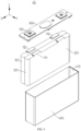
- FIG. 3 is a schematic structural diagram of a battery cell 40 according to some embodiments of this application
- FIG. 4 is a schematic exploded view of a battery cell 40 according to some embodiments of this application
- FIG. 5 is a schematic diagram of a process of preparing a battery cell 40 according to some embodiments of this application.
- the battery cell 40 includes: an end cap assembly 300, a housing 400, an electrode assembly 100, and an insulation piece 200.
- the end cap assembly 300 includes an electrode terminal 310.
- An opening 410 is provided on the housing 400.
- the end cap assembly 300 seals the opening 410.
- the electrode assembly 100 is disposed in the housing 400.
- the electrode assembly 100 includes a tab 110.
- An adapter component 500 is connected between the tab 110 and the electrode terminal 310.
- the adapter component 500 includes a first connecting region 510 configured to be connected to the electrode terminal 310, a second connecting region 520 configured to be connected to the tab 110, and a transitional connecting region 530 located between the first connecting region 510 and the second connecting region 520.
- the insulation piece 200 covers at least a part of the transitional connecting region 530.
- the housing 400 and the end cap assembly 300 are combined to form a shell of the battery cell 40.
- the electrode assembly 100 and the insulation piece 200 are located in the housing 400.
- the end cap assembly 300 is a component that caps off the opening 410 of the housing 400 to isolate the internal environment of the battery cell 40 from the external environment.
- the shape of the end cap assembly 300 may be adapted to the shape of the housing 400 to fit the housing 400.
- the end cap assembly 300 may be made of a material of appropriate hardness and strength (such as aluminum alloy), so that the end cap assembly 300 is not prone to deform when squeezed or impacted. In this way, the battery cell 40 achieves higher structural strength and higher safety performance.
- Functional components such as an electrode terminal 310 may be disposed on the end cap assembly 300.
- the electrode terminal 310 may be configured to be electrically connected to the electrode assembly 100 to output or input electrical energy of the battery cell 40.
- a pressure relief mechanism configured to release an internal pressure when the internal pressure or temperature of the battery cell 40 reaches a threshold may be further disposed on the end cap assembly 300.
- the end cap assembly 300 may also be made of a variety of materials such as copper, iron, aluminum, stainless steel, aluminum alloy, or plastic, and the materials are not particularly limited herein.
- the electrode assembly 100 may further include an electrode body 120.
- the tab 110 extends out from one side of the electrode body 120.
- the electrode body 120 is primarily formed by winding an electrode plate 100a and separator 100b, where the electrode plate is coated with an active material.
- the electrode plate 100a includes a positive electrode plate and a negative electrode plate.
- the tab 110 extends beyond the electrode body 120.
- the tab 110 and the electrode body 120 are combined to form the electrode assembly 100.
- the electrode assembly 100 is a component in which electrochemical reactions occur in the battery cell 40.
- the housing 400 may contain one or more electrode assemblies 100.
- the tab 110 includes a positive tab and a negative tab.
- the part coated with no active material on the positive electrode plate forms a positive tab
- the part coated with no active material on the negative electrode plate forms a negative tab.
- the positive tab and the negative tab may be located together at one end of the electrode body 120 or located at two ends of the electrode body 120 respectively.
- the housing 400 is a component configured to fit the end cap assembly 300 to form an internal environment of the battery cell 40.
- the formed internal environment may be used to accommodate the electrode assembly 100, an electrolyte solution (not shown in the drawing), and other components.
- the housing 400 and the end cap assembly 300 may be stand-alone components.
- An opening 410 may be provided on the housing 400. At the opening 410, the end cap assembly 300 caps off the opening 410 to form the internal environment of the battery cell 40.
- the end cap assembly 300 and the housing 400 may be integrated instead.
- the end cap assembly 300 and the housing 400 may form a common connection interface before other components are put into the housing. Subsequently, when the interior of the housing 400 needs to be sealed, the end cap assembly 300 is made to fit with the housing 400.
- the housing 400 may be in various shapes and sizes, such as a cuboid, cylinder, or hexagonal prism. Specifically, the shape of the housing 400 may depend on the specific shape and size of the electrode assembly 100.
- the housing 400 may be made of a variety of materials such as copper, iron, aluminum, stainless steel, aluminum alloy, or plastic, without being particularly limited herein.
- the adapter component 500 is configured to connect the tab 110 and the electrode terminal 310.
- the adapter component 500 may be in various shapes as long as the adapter component 500 can extend between the tab 110 and the electrode terminal 310 and as long as the adapter component 500 includes a first connecting region 510 connected to the electrode terminal 310, a second connecting region 520 connected to the tab 110, and a transitional connecting region 530 located between the first connecting region 510 and the second connecting region 520.
- the adapter component 500 may be made of a material including a metal material.
- the material of the adapter component 500 may include a copper material, an aluminum material, or the like.
- the adapter component 500 may be connected between the tabs 110 of the at least two electrode assemblies 100 and the same electrode terminal 310.
- the at least two tabs 110 connected to the adapter component 500 are tabs 110 of the same polarity.
- at least a part of the adapter component 500 is located between an end face of the electrode body 120 and the end cap assembly 300.
- the positive tab may be connected to the positive electrode terminal by one adapter component 500, and the negative tab may be connected to the negative electrode terminal by another adapter component 500.
- the insulation piece 200 may cover at least a part of the transitional connecting region 530 of at least one adapter component 500.
- the insulation piece 200 may be made of a variety of materials.
- the insulation piece 200 may be made of insulating materials such as rubber or plastic.
- the insulation piece 200 is made of rubber so that the insulation piece 200 is of appropriate elasticity, thereby improving the resilience of the transitional connecting region 530 under stress.
- the insulation piece 200 may cover a surface of the transitional connecting region 530, the surface being oriented toward the end cap assembly 300.
- the insulation piece 200 may be located on a surface of the transitional connecting region 530, the surface being oriented toward the electrode body 120.
- the insulation piece 200 may wrap around the transitional connecting region 530.
- the battery cell 40 includes an end cap assembly 300, a housing 400, an electrode assembly 100, an adapter component 500, and an insulation piece 200.
- the end cap assembly 300 seals the opening 410 of the housing 400.
- the electrode assembly 100 is located in the housing 400.
- the end cap assembly 300 and the housing 400 can provide protection for the electrode assembly 100.
- the adapter component 500 is connected between the tab 110 and the electrode terminal 310 through its own first connecting region 510 and second connecting region 520, and is configured to lead the electrical energy of the electrode assembly 100 out of the housing 400.
- the insulation piece 200 covers at least a part of the transitional connecting region 530.
- the insulation piece 200 can provide protection for the transitional connecting region 530, increase the service life of the transitional connecting region 530, and alleviate the problem that the transitional connecting region 530 is prone to be broken by vibration; on the other hand, the insulation piece 200 covers the transitional connecting region 530, so that the transitional connecting region 530 can keep insulated from the electrode assembly 100 or the end cap assembly 300 when breaking off, thereby alleviating the short-circuiting between the adapter component 500 and the electrode assembly 100 or the end cap assembly 300, and improving the safety performance of the battery cell 40.
- the transitional connecting region 530 heats up faster than the first connecting region 510 and the second connecting region 520, so that the transitional connecting region 530 can melt and break more easily to cut off the current flow path between the tab 110 and the electrode terminal 310, thereby substantially preventing the battery cell 40 from exploding due to overcurrent. Therefore, in this embodiment of this application, the insulation piece 200 covers the transitional connecting region 530 of the adapter component 500, thereby improving the service life and safety performance of the battery cell 40.
- a minimum cross-sectional area of the transitional connecting region 530 is greater than or equal to a minimum cross-sectional area of the first connecting region 510, and/or a minimum cross-sectional area of the transitional connecting region 530 is greater than or equal to a minimum cross-sectional area of the second connecting region 520.
- the cross-sectional area of the transitional connecting region 530 is the cross-sectional area of the transitional connecting region 530 in the thickness direction Z of the adapter component 500.
- the minimum cross-sectional area of the transitional connecting region 530 means the minimum cross-sectional area of the transitional connecting region 530 in the thickness direction Z.
- the minimum cross-sectional area of the first connecting region 510 means the minimum cross-sectional area of the first connecting region 510 in the thickness direction Z
- the minimum cross-sectional area of the second connecting region 520 means the minimum cross-sectional area of the second connecting region 520 in the thickness direction Z.
- the first direction X is a length direction
- the second direction Y is a width direction
- the first connecting region 510 and the second connecting region 520 are spaced apart along the first direction X.
- the minimum cross-sectional area of the transitional connecting region 530 may be the cross-sectional area at the minimum-width position of the transitional connecting region 530, that is, the cross-sectional area at a position where the transitional connecting region 530 extends by the smallest amount of dimension in the second direction Y.
- the first direction X may be the length direction of the electrode assembly 100.
- the second direction Y may be a direction in which the plurality of electrode assemblies 100 are arranged in parallel.
- the cross-sectional area of the transitional connecting region 530 is relatively large.
- the transitional connecting region 530 is not prone to break when the battery cell 40 vibrates, thereby increasing the service life of the adapter component 500.
- the transitional connecting region 530 heats up more quickly and can melt and break more easily, thereby improving the safety performance of the battery cell 40. Therefore, in such embodiments of this application, the adapter component 500 subjected to heat is made to melt and break easily on the premise of not affecting the service life of the adapter component 500, thereby improving the safety performance of the battery cell 40.
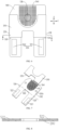
- FIG. 6 is a schematic structural diagram of coordination between an adapter component and an insulation piece in a battery cell 40 according to some embodiments of this application;
- FIG. 7 is a schematic exploded view of FIG. 6;
- FIG. 8 is a cross-sectional view of sectioning along an A-A line shown in FIG. 6 .
- the insulation piece 200 surrounds an outer circumference of the transitional connecting region 530.
- That the insulation piece 200 surrounds an outer circumference of the transitional connecting region 530 means that the insulation piece 200 is cylindrical and is sleeved around the transitional connecting region 530, so that the circumference of the transitional connecting region 530 is entirely covered by the insulation piece 200.
- the insulation piece 200 is disposed around the transitional connecting region 530.
- the insulation piece 200 wraps the entire transitional connecting region 530, thereby further improving the protection performance of the insulation piece 200 and more effectively alleviating the short-circuiting between the adapter component 500 and the electrode assembly 100 or the end cap assembly 300.
- the temperature rise of the transitional connecting region 530 wrapped by the insulation piece 200 is faster, so that the transitional connecting region 530 can melt and break more easily, thereby further improving the safety performance of the battery cell 40.
- At least a part of the tab 110 covers the insulation piece 200.
- An edge 110a, oriented toward the first connecting region 510, of the tab 110 does not extend beyond the insulation piece 200.
- That the tab 110 covers the insulation piece 200 includes: the tab 110 covers only the second connecting region 520; or, the tab 110 extends from the second connecting region 520 toward the first connecting region 510, that is, the tab 110 may cover at least a part of the transitional connecting region 530, as long as the edge 110a, oriented toward the first connecting region 510, of the tab 110 does not extend beyond the insulation piece 200.
- the edge 110a, oriented toward the first connecting region 510, of the tab 110 means an edge, close to the first connecting region 510, of the tab 110.
- the edge 110a is the edge of the staggered tabs.
- the edge 110a may be the edge of the tabs 110 at a position where the staggering amount falls within a specified staggering tolerance threshold.
- the edge of the tab 110 does not extend beyond the insulation piece 200, thereby preventing the tab 110 from crossing the insulation piece 200 and lapping the adapter component 500, and in turn, alleviating the short-circuiting problem of the battery cell 40.
- the tab 110 includes a positive tab and a negative tab.
- the adapter component 500 connects the positive tab and the electrode terminal 310.
- a first cross-sectional area of the transitional connecting region 530 is A
- a second cross-sectional area of the tab 110 is B
- the first cross-sectional area and the second cross-sectional area satisfy 3A ⁇ 2B.
- the positive tab may be connected to the positive electrode terminal by the adapter component 500 described in any one of the above embodiments.
- the insulation piece 200 may be omitted on another adapter component that connects the negative tab to the negative electrode terminal.
- the transitional connecting region 530 is more easily breakable than the negative tab, so that the current flow path between the positive tab and the electrode terminal 310 can be cut off in time, thereby further improving the safety performance of the battery cell 40.
- the adapter component 500 may be made of a material including aluminum or copper.
- the tab 110 may also be made of a material including aluminum or copper.
- the flow capacity of aluminum is approximately 4 A/mm 2 to 5 A/mm 2 .
- the flow capacity of aluminum is 5 A/mm 2 .
- the flow capacity of copper is approximately 7 A/mm 2 to 9 A/mm 2 .
- the flow capacity of copper is 8 A/mm 2 .
- the positive tab and the adapter component 500 are made of a material including aluminum, and the negative tab is made of a material including copper.
- the positive tab and the adapter component 500 are made of the same material.
- the connection strength can be increased between the positive tab and the adapter component 500.
- the negative tab includes copper.
- the tab 110 includes a plurality of sub-tabs.
- a thickness of each sub-tab is Z
- the number of the sub-tabs is X
- a plurality of sub-tabs of the tab 110 are stacked up together.
- the width D of the sub-tab is the average width of the plurality of sub-tabs.
- the tab 110 is generally formed by stacking a plurality of sub-tabs.
- the second cross-sectional area of the tab 110 is a sum of the cross-sectional areas of THE plurality of stacked sub-tabs, so that the calculation of the second cross-sectional area of the tab 110 is more accurate.
- the transitional connecting region 530 includes a first part 531 connected to the first connecting region 510 and a second part 532 connected to the second connecting region 520.
- a cross-sectional area of the first part 531 is greater than a cross-sectional area of the second part 532.
- the first part 531 includes a penetrating through-hole 532a. At least a part of the insulation piece 200 is embedded in the through-hole 532a.
- the dashed line in FIG. 7 shows a boundary between the first part 531 and the second part 532. The dashed line does not constitute any limitation on the structure of the battery cell according to an embodiment of this application.
- the insulation piece 200 is partially embedded in the through-hole 532a, thereby improving the stability of the relative position between the insulation piece 200 and the adapter component 500.
- the second connecting region 520 protrudes beyond the first connecting region 510.
- the transitional connecting region 530 includes a corner part 533.
- the insulation piece 200 covers at least the corner part 533.
- the dimensional difference between the second connecting region 520 and the first connecting region 510 or the bending of the adapter component 500 gives rise to a corner part 533 in the transitional connecting region 530.
- the corner part 533 is prone to stress concentration, thereby causing the corner part 533 to be prone to be broken by mechanical vibration, in turn, impairing the service life of the adapter component 500.
- the insulation piece 200 covering the corner part 533 can provide protection for the corner part 533 and alleviate the problem that the corner part 533 is prone to be damaged by collision.
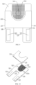
- FIG. 9 is a schematic structural diagram of an adapter component and an insulation piece in a battery cell 40 according to some other embodiments of this application; and FIG. 10 is a schematic exploded view of FIG. 9 .
- the electrode assembly 100 includes a first electrode assembly 101 and a second electrode assembly 102.
- the first electrode assembly 101 includes a first tab 111.
- the second electrode assembly 102 includes a second tab 112.
- the second connecting region 520 includes a first sub-region 521 configured to be connected to the first tab 111 and a second sub-region 522 configured to be connected to the second tab 112.
- the transitional connecting region 530 includes a first partition 534 located between the first sub-region 521 and the first connecting region 510 as well as a second partition 535 located between the second sub-region 522 and the first connecting region 510.
- the insulation piece 200 includes a first subsection 210 configured to cover at least a part of the first partition 534 and a second subsection 220 configured to cover at least a part of the second partition 535.
- the first subsection 210 and the second subsection 220 are separate from each other or formed in one piece.
- the first tab 111 and the second tab 112 may be positive tabs, or, the first tab 111 and the second tab 112 may be negative tabs.
- the battery cell 40 includes a plurality of electrode assemblies 100, that is, a first electrode assembly 101 and a second electrode assembly 102.
- the plurality of electrode assemblies 100 can increase the capacitance of the battery cell 40.
- a first tab 111 is disposed on the first electrode assembly 101
- a second tab 112 is disposed on the second electrode assembly 102.
- the second connecting region 520 can be connected to the first tab 111 and the second tab 112 simultaneously through the first sub-region 521 and the second sub-region 522 respectively, so that the same connecting component connects the electrode terminal 310 to the tabs of the two electrode assemblies 100.
- the corresponding transitional connecting region 530 includes a first partition 534 located between the first sub-region 521 and the first connecting region 510, and a second partition 535 located between the second sub-region 522 and the first connecting region 510.
- the insulation piece 200 includes a first subsection 210 and a second subsection 220. The first subsection 210 and the second subsection 220 cover the first partition 534 and the second partition 535, respectively.
- both the first partition 534 and the second partition 535 can be easily broken, thereby cutting off the current flow path between the first tab 111 and the electrode terminal 310 as well as the current flow path between the second tab 112 and the electrode terminal 310 in time, and further improving the safety performance of the battery cell 40.
- the first subsection 210 and the second subsection 220 may be disposed separately. In other words, the first subsection 210 and the second subsection 220 are spaced apart.
- the first subsection 210 and the second subsection 220 may be formed in one piece to simplify the structure of the insulation piece 200 and increase the structural strength of the insulation piece 200.
- the first partition 534 and the second partition 535 are disposed separately, that is, when the first partition 534 and the second partition 535 are spaced apart along the second direction Y, a corner part 533 is disposed between the first partition 534 and the second partition 535.
- the first subsection 210 and the second subsection 220 being formed in one piece can cover the corner part 533 more effectively.
- the first sub-region 521 and the second sub-region 522 may be spaced apart from each other.
- the first sub-region 521 and the second sub-region 522 are spaced apart along a direction in which the first electrode assembly 101 and the second electrode assembly 102 are arranged in parallel, so as to reduce the required amount of material of the adapter component 500.
- the first partition 534 and the second partition 535 may be disposed separately to further reduce the required amount of material of the adapter component 500.
Landscapes
- Chemical & Material Sciences (AREA)
- Chemical Kinetics & Catalysis (AREA)
- Electrochemistry (AREA)
- General Chemical & Material Sciences (AREA)
- Connection Of Batteries Or Terminals (AREA)
Abstract
Description
- This application relates to the field of batteries, and in particular, to a battery cell, a battery, and an electrical device.
- Energy conservation and emission reduction are key to sustainable development of the automobile industry. Electric vehicles have become an important part of the sustainable development of the automobile industry by virtue of energy saving and environmental friendliness. Battery technology is crucial to the development of electric vehicles.
- A battery cell includes a housing, an end cap assembly that caps off an opening of the housing, and an electrode assembly located in the housing. An electrode terminal is disposed on the end cap assembly. A tab of the electrode assembly is connected to the electrode terminal by an adapter component. During the transportation or use of the battery cell, the battery cell may incur problems such as thermal runaway, thereby impairing the safety performance of the battery cell.
- In view of the above problems, this application provides a battery cell, a battery, and an electrical device to improve the safety performance of the electrode body.
- According to a first aspect, this application provides a battery cell. The battery cell includes: an end cap assembly, including an electrode terminal; a housing, on which an opening is provided, where the end cap assembly seals the opening; an electrode assembly, disposed in the housing, where the electrode assembly includes a tab; an adapter component, connected between the tab and the electrode terminal, where the adapter component includes a first connecting region configured to be connected to the electrode terminal, a second connecting region configured to be connected to the tab, and a transitional connecting region located between the first connecting region and the second connecting region; and an insulation piece, covering at least a part of the transitional connecting region.
- In the technical solution disclosed in an embodiment of this application, the battery cell includes an end cap assembly, a housing, an electrode assembly, an adapter component, and an insulation piece. The end cap assembly seals the opening of the housing. The electrode assembly is located in the housing. The end cap assembly and the housing can provide protection for the electrode assembly. The adapter component is connected between the tab and the electrode terminal through its own first connecting region and second connecting region, and is configured to lead the electrical energy of the electrode assembly out of the housing. The insulation piece covers at least a part of the transitional connecting region. On the one hand, the insulation piece can provide protection for the transitional connecting region, increase the service life of the transitional connecting region, and alleviate the problem that the transitional connecting region is prone to be broken by vibration; on the other hand, the insulation piece covers the transitional connecting region, so that the transitional connecting region can keep insulated from the electrode assembly or the end cap assembly when breaking off, thereby alleviating the short-circuiting between the adapter component and the electrode assembly or the end cap assembly, and improving the safety performance of the battery cell. In addition, when the battery cell is overcharged or an overcurrent flows through the battery cell due to other abnormalities, because the transitional connecting region is covered by the insulation piece, the transitional connecting region heats up faster than the first connecting region and the second connecting region, so that the transitional connecting region can melt and break more easily to cut off the current flow path between the tab and the electrode terminal, thereby substantially preventing the battery cell from exploding due to overcurrent. Therefore, in this application, the insulation piece covers the transitional connecting region of the adapter component, thereby improving the service life and safety performance of the battery cell.
- In some embodiments, a minimum cross-sectional area of the transitional connecting region is greater than or equal to a minimum cross-sectional area of the first connecting region, and/or a minimum cross-sectional area of the transitional connecting region is greater than or equal to a minimum cross-sectional area of the second connecting region. In this embodiment, the cross-sectional area of the transitional connecting region is relatively large. The transitional connecting region is not prone to break when the battery cell vibrates, thereby increasing the service life of the adapter component. When thermal runaway occurs in the battery cell, because the insulation piece covers the transitional connecting region, the transitional connecting region heats up more quickly and can melt and break more easily, thereby improving the safety performance of the battery cell. Therefore, in this embodiment of this application, the adapter component subjected to heat is made to melt and break easily on the premise of not affecting the service life of the adapter component, thereby improving the safety performance of the battery cell.
- In some embodiments, the insulation piece surrounds an outer circumference of the transitional connecting region. In this embodiment, the insulation piece is disposed around the transitional connecting region. In other words, the insulation piece wraps the entire transitional connecting region, thereby further improving the protection performance of the insulation piece and more effectively alleviating the short-circuiting between the adapter component and the electrode assembly or the end cap assembly. In addition, when the battery cell is thermally runaway, the temperature rise of the transitional connecting region wrapped by the insulation piece is faster, so that the transitional connecting region can melt and break more easily, thereby further improving the safety performance of the battery cell.
- In some embodiments, at least a part of the tab covers the insulation piece. An edge, oriented toward the first connecting region, of the tab does not extend beyond the insulation piece. In these embodiments, the edge of the tab does not extend beyond the insulation piece, thereby preventing the tab from crossing the insulation piece and lapping the adapter component, and in turn, alleviating the short-circuiting problem of the battery cell.
- In some embodiments, the tab includes a positive tab and a negative tab. The adapter component connects the positive tab and the electrode terminal. A first cross-sectional area of the transitional connecting region is A, a second cross-sectional area of the tab is B, and the first cross-sectional area and the second cross-sectional area satisfy 3A < 2B. In these embodiments, when the first cross-sectional area and the second cross-sectional area satisfy the above relation, in a case that the battery cell is thermally runaway, the transitional connecting region of the adapter component is more easily breakable than the negative tab, so that the current flow path between the positive tab and the electrode terminal can be cut off in time, and so that the adapter component can be broken before the negative tab breaks, thereby further improving the safety performance of the battery cell.
- In some embodiments, the positive tab and the adapter component are made of a material including aluminum, and the negative tab is made of a material including copper. In these embodiments, the positive tab and the adapter component are made of the same material. When the positive tab is welded to the adapter component, the connection strength can be increased between the positive tab and the adapter component. The negative tab includes copper. When the first cross-sectional area and the second cross-sectional area satisfy the above relation, the adapter component can be broken before the negative tab.
- In some embodiments, the tab includes a plurality of sub-tabs. A thickness of each sub-tab is Z, the number of the sub-tabs is X, and a width of the sub-tab is D, satisfying: B = X × D × Z. In these embodiments, the second cross-sectional area of the tab is a sum of the cross-sectional areas of a plurality of stacked sub-tabs, so that the calculation of the second cross-sectional area of the tab is more accurate.
- In some embodiments, the transitional connecting region includes a first part connected to the first connecting region and a second part connected to the second connecting region. A cross-sectional area of the first part is greater than a cross-sectional area of the second part. The first part includes a penetrating through-hole. At least a part of the insulation piece is embedded in the through-hole. In these embodiments, the insulation piece is partially embedded in the through-hole, thereby improving the stability of the relative position between the insulation piece and the adapter component.
- In some embodiments, the second connecting region protrudes beyond the first connecting region. The transitional connecting region includes a corner part. The insulation piece covers at least the corner part. In these embodiments, the insulation piece covering the corner part can provide protection for the corner part and alleviate the problem that the corner part is prone to be damaged by collision.
- In some embodiments, the electrode assembly includes a first electrode assembly and a second electrode assembly. The first electrode assembly includes a first tab. The second electrode assembly includes a second tab. The second connecting region includes a first sub-region configured to be connected to the first tab and a second sub-region configured to be connected to the second tab. The transitional connecting region includes a first partition located between the first sub-region and the first connecting region as well as a second partition located between the second sub-region and the first connecting region. The insulation piece includes a first subsection configured to cover at least a part of the first partition and a second subsection configured to cover at least a part of the second partition. The first subsection and the second subsection are separate from each other or formed in one piece.
- In these embodiments, the number of electrode assemblies is plural. Each of the electrode assemblies includes a tab. In other words, the electrode assembly includes a first electrode assembly and a second electrode assembly, the first electrode assembly includes a first tab, and the second electrode assembly includes a second tab. The adapter component connects the tabs of the plurality of electrode assemblies. In other words, the second connecting region is connected to the first tab by using the first sub-region, and the second connecting region is connected to the second tab by using the second sub-region. The transitional connecting region includes a first partition located between the first sub-region and the first connecting region, and a second partition located between the second sub-region and the first connecting region. The insulation piece includes a first subsection and a second subsection. The first subsection and the second subsection cover the first partition and the second partition, respectively. In this way, when the battery cell is thermally runaway, both the first partition and the second partition can be easily broken, thereby cutting off the current flow path between the first tab and the electrode terminal as well as the current flow path between the second tab and the electrode terminal in time, and further improving the safety performance of the battery cell.
- In some embodiments, the first sub-region and the second sub-region are interconnected into one piece, the first partition and the second partition are interconnected into one piece, and the first subsection and the second subsection are interconnected into one piece. In these embodiments, the first sub-region and the second sub-region are interconnected into one piece, and the second partition and the first partition are interconnected into one piece, thereby simplifying the structure of the adapter component. The first subsection and the second subsection are interconnected into one piece, thereby simplifying the structure of the insulation piece.
- In some embodiments, the adapter component further includes an embossed region. The first connecting region is located inside the embossed region, and the insulation piece and the embossed region are spaced apart. In these embodiments, the first connecting region is located inside the embossed region, and the electrode terminal and the adapter component are interconnected in the embossed region. For example, the electrode terminal and the adapter component are welded to each other in the embossed region. The insulation piece and the embossed region are spaced apart, thereby alleviating the impact of high temperature on the insulation piece during welding, and alleviating the problem of the insulation piece melting due to heat.
- In some embodiments, a minimum distance between the insulation piece and the first connecting region is 0.5 mm to 4 mm, and/or a minimum distance between the insulation piece and the second connecting region is 0.5 mm to 4 mm.
- In these embodiments, the minimum distance between the insulation piece and the first connecting region is 0.5 mm to 4 mm, thereby alleviating the problem that the insulation piece is prone to be deformed by heat during welding between the first connecting region and the electrode terminal due to an insufficient distance between the insulation piece and the first connecting region. On the other hand, this setting also alleviates the problem that the transitional connecting region can be hardly melted off due to an insufficient temperature rise speed at the transitional connecting region, where the insufficient temperature rise speed is caused by an insufficient size of the insulation piece that arises from an excessive distance between the insulation piece and the first connecting region. The minimum distance between the insulation piece and the second connecting region is 0.5 mm to 4 mm, thereby alleviating the problem that the insulation piece is prone to be deformed by heat during welding between the second connecting region and the tab due to an insufficient distance between the insulation piece and the second connecting region. On the other hand, this setting also alleviates the problem that the transitional connecting region can be hardly melted off due to an insufficient temperature rise speed at the transitional connecting region, where the insufficient temperature rise speed is caused by an insufficient size of the insulation piece that arises from an excessive distance between the insulation piece and the first connecting region.
- According to a second aspect, an embodiment of this application further provides a battery. The battery includes the battery cell according to any one of the embodiments in the first aspect. The battery cell is configured to provide electrical energy.
- According to a third aspect, an embodiment of this application further provides an electrical device. The electrical device includes the battery cell according to any one of the embodiments in the first aspect.
- The foregoing description is merely an overview of the technical solutions of this application. Some specific embodiments of this application are described below illustratively to enable a clearer understanding of the technical solutions of this application, enable implementation of the technical solutions based on the subject-matter hereof, and make the foregoing and other objectives, features, and advantages of this application more evident and comprehensible.
- By reading the following detailed description of exemplary embodiments, a person of ordinary skill in the art becomes clearly aware of various other advantages and benefits. The drawings are merely intended to illustrate the exemplary embodiments, but not to limit this application. In all the drawings, the same reference numeral represents the same component. In the drawings:
-
FIG. 1 is a schematic structural diagram of a vehicle according to an embodiment of this application; -
FIG. 2 is a schematic structural diagram of a battery pack according to an embodiment of this application; -
FIG. 3 is a schematic structural diagram of a battery cell according to an embodiment of this application; -
FIG. 4 is a schematic exploded view of a battery cell according to an embodiment of this application; -
FIG. 5 is a schematic diagram of a process of preparing a battery cell according to an embodiment of this application; -
FIG. 6 is a schematic structural diagram of mutual coordination between an adapter component and an insulation piece in a battery cell according to an embodiment of this application; -
FIG. 7 is a schematic exploded view ofFIG. 6 ; -
FIG. 8 is a cross-sectional view of sectioning along an A-A line shown inFIG. 6 ; -
FIG. 9 is a schematic structural diagram of mutual coordination between an adapter component and an insulation piece in a battery cell according to another embodiment of this application; -
FIG. 10 is a schematic exploded view ofFIG. 9 ; -
FIG. 11 is a schematic structural diagram of mutual coordination between an adapter component and an insulation piece in a battery cell according to still another embodiment of this application; and -
FIG. 12 is a schematic exploded view ofFIG. 11 . -
- 1. vehicle; 10. battery; 11. controller; 12. motor;
- 20. battery module;
- 30. box; 301. first box portion; 302. second box portion;
- 40. battery cell;
- 100. electrode assembly; 101. first electrode assembly; 102. second electrode assembly; 110. tab; 110a. edge; 111. first tab; 112. second tab; 120. electrode body;
- 200. insulation piece; 210. first subsection; 220. second subsection;
- 300. end cap assembly; 310. electrode terminal;
- 400. housing; 410. opening;
- 500. adapter component; 510. first connecting region; 520. second connecting region; 521. first sub-region; 522. second sub-region; 530. transitional connecting region; 531. first part; 532. second part; 532a. through-hole; 533. corner part; 534. first partition; 535. second partition; 540. embossed region;
- X. first direction; Y. second direction; Z. third direction
- Some embodiments of the technical solutions of this application are described in detail below with reference to the drawings. The following embodiments are merely intended as examples to describe the technical solutions of this application more clearly, but not intended to limit the protection scope of this application.
- It is hereby noted that, unless otherwise specified, the technical terms or scientific terms used in embodiments of this application bear the meanings commonly understood by a person skilled in the technical field of embodiments of this application.
- In the description of embodiments of this application, a direction or a positional relationship indicated by the terms such as "center", "longitudinal", "transverse", "length", "width", "thickness", "up", "down", "before", "after", "left", "right", "vertical", "horizontal", "top", "bottom", "in", "out", "clockwise", "counterclockwise", "axial", "radial", and "circumferential" is a direction or positional relationship based on the illustration in the drawings, and is merely intended for ease or brevity of description of embodiments of this application, but not intended to indicate or imply that the indicated device or component is necessarily located in the specified direction or constructed or operated in the specified direction. Therefore, such terms are not to be understood as a limitation on embodiments of this application.
- In addition, the technical terms such as "first" and "second" are used merely for ease of description, but not to indicate or imply relative importance or implicitly specify the number of technical features mentioned. In the description of some embodiments of this application, unless otherwise expressly specified, "a plurality of" means two or more.
- In the description of embodiments of this application, unless otherwise expressly specified and defined, the technical terms such as "mount", "concatenate", "connect", and "fix" are generic in a broad sense, for example, mean a fixed connection, a detachable connection, or a one-piece configuration; or mean a mechanical connection or an electrical connection; or mean a direct connection or an indirect connection implemented through an intermediary; or mean internal communication between two components or interaction between two components. A person of ordinary skill in the art can understand the specific meanings of the terms in some embodiments of this application according to specific situations.
- In the description of embodiments of this application, unless otherwise expressly specified and defined, a first feature being "on" or "under" a second feature may mean that the first feature is in direct contact with the second feature, or the first feature is in indirect contact with the second feature through an intermediary. In addition, a first feature being "on", "above", or "over" a second feature may be that the first feature is exactly above or obliquely above the second feature, or simply that the first feature is at an altitude higher than the second feature. A first feature being "under", "below", or "beneath" a second feature may be that the first feature is exactly under or obliquely under the second feature, or simply that the first feature is at an altitude lower than the second feature.
- Currently, as can be seen from the market trend, the application of power batteries is increasingly extensive. Power batteries are not only used in energy storage power systems such as hydro, thermal, wind, and solar power stations, but also widely used in electric means of transport such as electric bicycles, electric motorcycles, and electric vehicles, and used in many other fields such as military equipment and aerospace. The market demand for power batteries keeps soaring with the expansion of the application fields of the power batteries.
- In this application, a battery cell may include a lithium-ion secondary battery cell, a lithium-ion primary battery cell, a lithium-sulfur battery cell, a sodium-lithium-ion battery cell, a sodium-ion battery cell, a magnesium-ion battery cell, or the like. The embodiments of this application do not limit the type of the battery cell. The battery cell may be in various shapes such as cylindrical, flat, cuboidal or other shapes. The shape of the battery cell is not limited herein.
- The battery mentioned in embodiments of this application means a unitary physical module that includes one or more battery cells to provide a higher voltage and a higher capacity. For example, the battery mentioned in this application may include a battery module, a battery pack, or the like. A battery typically includes a box configured to package one or more battery cells. The box prevents liquid or other foreign matters from affecting the charging or discharging of the battery cells.
- A battery cell includes an electrode assembly and an electrolyte solution. The electrode assembly includes a positive electrode plate, a negative electrode plate, and a separation plate. The battery cell works primarily by shuttling metal ions between the positive electrode plate and the negative electrode plate. The positive electrode plate includes a positive current collector and a positive active material layer. The positive active material layer overlays a surface of the positive current collector. The positive current collector includes a positive current collecting portion and a positive tab connected to the positive current collecting portion. The positive current collecting portion is coated with a positive active material layer, and the positive tab is not coated with the positive active material layer. Using a lithium-ion battery as an example, the positive current collector may be made of aluminum. The positive active material layer includes a positive active material. The positive active material may be lithium cobalt oxide, lithium iron phosphate, ternary lithium, lithium manganese oxide, or the like. The negative electrode plate includes a negative current collector and a negative active material layer. The negative active material layer is applied onto a surface of the negative current collector. The negative current collector includes a negative current collecting portion and a negative tab connected to the negative current collecting portion. The negative current collecting portion is coated with a negative active material layer, and the negative tab is not coated with the negative active material layer. The negative current collector may be made of copper. The negative active material layer includes a negative active material. The negative active material may be carbon, silicon, or the like. The separation plate may be made of a material such as PP (polypropylene) or PE (polyethylene).
- The inventor hereof is aware that a battery cell includes a housing, an end cap assembly that caps off an opening of the housing, and an electrode assembly located in the housing. A tab of the electrode assembly is connected to an electrode terminal on the end cap assembly by an adapter component. During the use of the battery cell, the battery cell may be overcharged or an overcurrent may flow through the battery cell due to other abnormalities. The overcurrent flow causes the temperature to rise, and gives rise to safety problems of the battery cell.
- In the related art, a fragile region is usually provided on the adapter component. When an overcurrent flows in the battery cell, the fragile region can melt and break more easily to cut off the current flow path between the tab and the electrode terminal. However, during the transportation and use of the battery cell, the fragile region is also prone to be broken off by mechanical vibration, thereby drastically impairing the service life of the adapter component and the battery cell.
- In order to solve the above technical problems, the applicant hereof has found through research that an insulation piece may cover a specified region of the adapter component. When an overcurrent flows in the battery cell, the part covered with the insulation piece heats up faster and breaks off more easily. At the same time, the insulation piece can provide protection for this region to alleviate the problem of this region being prone to be broken by mechanical vibration.
- In view of the above, in order to solve the safety problem caused by the overcurrent flow in the battery cell, the applicant hereby designs a battery cell, a battery, and an electrical device through in-depth research. In such a battery cell, the battery cell includes: an end cap assembly, including an electrode terminal; a housing, on which an opening is provided, where the end cap assembly seals the opening; an electrode assembly, disposed in the housing, where the electrode assembly includes a tab; an adapter component, connected between the tab and the electrode terminal, where the adapter component includes a first connecting region configured to be connected to the electrode terminal, a second connecting region configured to be connected to the tab, and a transitional connecting region located between the first connecting region and the second connecting region; and an insulation piece, covering at least a part of the transitional connecting region.
- The technical solution disclosed in this embodiment of this application is applicable to a battery and an electrical device that uses the battery.
- The electrical device may be a vehicle, a mobile phone, a portable device, a notebook computer, a ship, a spacecraft, an electric toy, an electric tool, or the like. The vehicle may be an oil-fueled vehicle, a natural gas vehicle, or a new energy vehicle. The new energy vehicle may be a battery electric vehicle, a hybrid electric vehicle, a range-extended electric vehicle, or the like. The spacecraft includes an airplane, a rocket, a space shuttle, a spaceship, and the like. The electric toy includes a fixed or mobile electric toy, such as a game console, an electric car toy, an electric ship toy, an electric airplane toy, and the like. The power tool includes an electrical metal cutting tool, an electrical grinding tool, an electrical assembling tool, and a power tool for use in railways. Examples of the power tool are an electrical drill, an electrical grinder, an electrical wrench, an electrical screwdriver, an electrical hammer, an electrical impact drill, a concrete vibrator, an electrical planer, and the like. The electrical device is not particularly limited in embodiments of this application.
- Understandably, the technical solutions described in an embodiment of this application are not only applicable to the battery and electrical device described above, but also applicable to all batteries containing a box and all electrical devices powered by a battery. However, for brevity, the following embodiments are described by using an electric vehicle as an example.
- Referring to
FIG. 1, FIG. 1 is a schematic structural diagram of avehicle 1 according to some embodiments of this application. Thevehicle 1 may be an oil-fueled vehicle, a natural gas vehicle, or a new energy vehicle. The new energy vehicle may be a battery electric vehicle, a hybrid electric vehicle, a range-extended electric vehicle, or the like. Abattery 10 is disposed inside thevehicle 1. Thebattery 10 may be disposed at the bottom, front, or rear of thevehicle 1. Thebattery 10 may be configured to supply power to thevehicle 1. For example, thebattery 10 may serve as an operating power supply of thevehicle 1. Thevehicle 1 may further include acontroller 11 and amotor 12. Thecontroller 11 is configured to control thebattery 10 to supply power to themotor 12, for example, to meet electrical energy requirements in starting, navigating, or running thevehicle 1. - In some embodiments of this application, the
battery 10 serves not only as an operating power supply of thevehicle 1, but may also serve as a driving power supply of thevehicle 1 to provide driving power for thevehicle 1 in place of or partly in place of fuel oil or natural gas. - To meet different power use requirements, the
battery 10 may include a plurality of battery cells. A battery cell is a minimum unit that makes up a battery module or battery pack. A plurality of battery cells may be connected together in series and/or parallel through electrode terminals, so as to be applied in various scenarios. A battery referred to in this application includes a battery module or a battery pack. The plurality of battery cells may be connected in series, parallel, or series-and-parallel pattern. The series-and-parallel pattern means a combination of series connection and parallel connection. In embodiments of this application, the plurality of battery cells may directly make up a battery pack, or form abattery module 20 before a plurality ofbattery modules 20 make up a battery pack. -
FIG. 2 is a schematic structural diagram of abattery 10 according to an embodiment of this application. - As shown in
FIG. 2 , thebattery 10 includes abox 30 and abattery cell 40. Thebattery cell 40 is accommodated in thebox 30. - The
box 30 may be a simple three-dimensional structure such as a stand-alone cuboid or cylinder or sphere, or may be a complex three-dimensional structure compounded of simple three-dimensional structures such as cuboids, cylinders or spheres, without being limited herein. The material of thebox 30 may be an alloy material such as aluminum alloy or iron alloy, or a polymer material such as polycarbonate or polyisocyanurate foam plastic, or a composite material compounded of glass fiber and epoxy resin, without being limited herein. - The
box 30 is configured to accommodate thebattery cell 40. Thebox 30 may be one of various structures. In some embodiments, thebox 30 may include afirst box portion 301 and asecond box portion 302. Thefirst box portion 301 and thesecond box portion 302 fit each other. Thefirst box portion 301 and thesecond box portion 302 together define an accommodation space configured to accommodate thebattery cell 40. Thesecond box portion 302 may be a hollow structure opened at one end. Thefirst box portion 301 is a plate structure. Thefirst box portion 301 fits and covers the opening of thesecond box portion 302 to form thebox 30 that includes the accommodation space. Alternatively, thefirst box portion 301 and thesecond box portion 302 each may be a hollow structure opened at one end. The opening of thefirst box portion 301 fits the opening of thesecond box portion 302 to form thebox 30 that includes the accommodation space. Definitely, thefirst box portion 301 and thesecond box portion 302 may be in various shapes, such as a cylinder or a cuboid. - To improve airtightness between the
first box portion 301 and thesecond box portion 302 that are connected, a sealing element such as a sealant or a sealing ring may be disposed between thefirst box portion 301 and thesecond box portion 302. - Assuming that the
first box portion 301 fits on the top of thesecond box portion 302, thefirst box portion 301 may also be referred to as an upper box, and thesecond box portion 302 may also be referred to as alower box 30. - The
battery 10 may contain one ormore battery cells 40. If there are a plurality ofbattery cells 40, the plurality ofbattery cells 40 may be connected in series, parallel, or series-and-parallel pattern. The series-and-parallel pattern means a combination of series connection and parallel connection of the plurality ofbattery cells 40. The plurality ofbattery cells 40 may be directly connected in series, parallel, or series-and-parallel pattern, and then the whole of the plurality ofbattery cells 40 may be accommodated in thebox 30. Alternatively, the plurality ofbattery cells 40 may be connected in series, parallel, or series-and-parallel pattern to form abattery module 20 first. A plurality ofbattery modules 20 are then connected in series, parallel, or series-and-parallel pattern to form a whole for being accommodated in thebox 30. - Still referring to
FIG. 2 , in some embodiments, there are a plurality ofbattery cells 40. The plurality ofbattery cells 40 are connected in series, parallel, or series-and-parallel pattern to form abattery module 20 first. A plurality ofbattery modules 20 are then connected in series, parallel, or series-and-parallel pattern to form a whole for being accommodated in thebox 30. - The plurality of
battery cells 40 in thebattery module 20 may be electrically connected by a busbar component, so as to implement parallel, series, or series-and-parallel connection between the plurality ofbattery cells 40 in thebattery module 20. - In this application, the
battery cell 40 may be a lithium-ion battery cell 40, a sodium-ion battery cell 40, a magnesium-ion battery cell 40, or the like. The type of the battery cell is not limited herein. Thebattery cell 40 may be in a cylindrical shape, a flat shape, a cuboidal shape, or other shapes, without being limited herein. Depending on the form of packaging, thebattery cell 40 is typically classed into three types:cylindrical battery cell 40,prismatic battery cell 40, and pouch-type battery cell 40, without being limited herein. For brevity, the following embodiments are described by using aprismatic cell 40 as an example. -
FIG. 3 is a schematic structural diagram of abattery cell 40 according to some embodiments of this application, andFIG. 4 is a schematic exploded view of abattery cell 40 according to some embodiments of this application.FIG. 5 is a schematic diagram of a process of preparing abattery cell 40 according to some embodiments of this application. - As shown in
FIG. 3 to FIG. 5 , thebattery cell 40 includes: anend cap assembly 300, ahousing 400, anelectrode assembly 100, and aninsulation piece 200. Theend cap assembly 300 includes anelectrode terminal 310. An opening 410 is provided on thehousing 400. Theend cap assembly 300 seals the opening 410. Theelectrode assembly 100 is disposed in thehousing 400. Theelectrode assembly 100 includes a tab 110. Anadapter component 500 is connected between the tab 110 and theelectrode terminal 310. Theadapter component 500 includes a first connectingregion 510 configured to be connected to theelectrode terminal 310, a second connectingregion 520 configured to be connected to the tab 110, and a transitional connectingregion 530 located between the first connectingregion 510 and the second connectingregion 520. Theinsulation piece 200 covers at least a part of the transitional connectingregion 530. - The
housing 400 and theend cap assembly 300 are combined to form a shell of thebattery cell 40. Theelectrode assembly 100 and theinsulation piece 200 are located in thehousing 400. - The
end cap assembly 300 is a component that caps off the opening 410 of thehousing 400 to isolate the internal environment of thebattery cell 40 from the external environment. Without limitation, the shape of theend cap assembly 300 may be adapted to the shape of thehousing 400 to fit thehousing 400. Optionally, theend cap assembly 300 may be made of a material of appropriate hardness and strength (such as aluminum alloy), so that theend cap assembly 300 is not prone to deform when squeezed or impacted. In this way, thebattery cell 40 achieves higher structural strength and higher safety performance. Functional components such as anelectrode terminal 310 may be disposed on theend cap assembly 300. Theelectrode terminal 310 may be configured to be electrically connected to theelectrode assembly 100 to output or input electrical energy of thebattery cell 40. - In some embodiments, a pressure relief mechanism configured to release an internal pressure when the internal pressure or temperature of the
battery cell 40 reaches a threshold may be further disposed on theend cap assembly 300. Theend cap assembly 300 may also be made of a variety of materials such as copper, iron, aluminum, stainless steel, aluminum alloy, or plastic, and the materials are not particularly limited herein. - The
electrode assembly 100 may further include an electrode body 120. The tab 110 extends out from one side of the electrode body 120. The electrode body 120 is primarily formed by winding an electrode plate 100a and separator 100b, where the electrode plate is coated with an active material. The electrode plate 100a includes a positive electrode plate and a negative electrode plate. The tab 110 extends beyond the electrode body 120. The tab 110 and the electrode body 120 are combined to form theelectrode assembly 100. Theelectrode assembly 100 is a component in which electrochemical reactions occur in thebattery cell 40. Thehousing 400 may contain one ormore electrode assemblies 100. The tab 110 includes a positive tab and a negative tab. The part coated with no active material on the positive electrode plate forms a positive tab, and the part coated with no active material on the negative electrode plate forms a negative tab. The positive tab and the negative tab may be located together at one end of the electrode body 120 or located at two ends of the electrode body 120 respectively. - The
housing 400 is a component configured to fit theend cap assembly 300 to form an internal environment of thebattery cell 40. The formed internal environment may be used to accommodate theelectrode assembly 100, an electrolyte solution (not shown in the drawing), and other components. Thehousing 400 and theend cap assembly 300 may be stand-alone components. An opening 410 may be provided on thehousing 400. At the opening 410, theend cap assembly 300 caps off the opening 410 to form the internal environment of thebattery cell 40. Without limitation, theend cap assembly 300 and thehousing 400 may be integrated instead. Specifically, theend cap assembly 300 and thehousing 400 may form a common connection interface before other components are put into the housing. Subsequently, when the interior of thehousing 400 needs to be sealed, theend cap assembly 300 is made to fit with thehousing 400. Thehousing 400 may be in various shapes and sizes, such as a cuboid, cylinder, or hexagonal prism. Specifically, the shape of thehousing 400 may depend on the specific shape and size of theelectrode assembly 100. Thehousing 400 may be made of a variety of materials such as copper, iron, aluminum, stainless steel, aluminum alloy, or plastic, without being particularly limited herein. - The
adapter component 500 is configured to connect the tab 110 and theelectrode terminal 310. Theadapter component 500 may be in various shapes as long as theadapter component 500 can extend between the tab 110 and theelectrode terminal 310 and as long as theadapter component 500 includes a first connectingregion 510 connected to theelectrode terminal 310, a second connectingregion 520 connected to the tab 110, and a transitional connectingregion 530 located between the first connectingregion 510 and the second connectingregion 520. Theadapter component 500 may be made of a material including a metal material. For example, the material of theadapter component 500 may include a copper material, an aluminum material, or the like. When at least twoelectrode assemblies 100 are disposed in thebattery cell 40, theadapter component 500 may be connected between the tabs 110 of the at least twoelectrode assemblies 100 and thesame electrode terminal 310. The at least two tabs 110 connected to theadapter component 500 are tabs 110 of the same polarity. Optionally, at least a part of theadapter component 500 is located between an end face of the electrode body 120 and theend cap assembly 300. - The positive tab may be connected to the positive electrode terminal by one
adapter component 500, and the negative tab may be connected to the negative electrode terminal by anotheradapter component 500. Theinsulation piece 200 may cover at least a part of the transitional connectingregion 530 of at least oneadapter component 500. Theinsulation piece 200 may be made of a variety of materials. Theinsulation piece 200 may be made of insulating materials such as rubber or plastic. Theinsulation piece 200 is made of rubber so that theinsulation piece 200 is of appropriate elasticity, thereby improving the resilience of the transitional connectingregion 530 under stress. Theinsulation piece 200 may cover a surface of the transitional connectingregion 530, the surface being oriented toward theend cap assembly 300. Alternatively, theinsulation piece 200 may be located on a surface of the transitional connectingregion 530, the surface being oriented toward the electrode body 120. Alternatively, theinsulation piece 200 may wrap around the transitional connectingregion 530. - In the technical solution disclosed in an embodiment of this application, the
battery cell 40 includes anend cap assembly 300, ahousing 400, anelectrode assembly 100, anadapter component 500, and aninsulation piece 200. Theend cap assembly 300 seals the opening 410 of thehousing 400. Theelectrode assembly 100 is located in thehousing 400. Theend cap assembly 300 and thehousing 400 can provide protection for theelectrode assembly 100. Theadapter component 500 is connected between the tab 110 and theelectrode terminal 310 through its own first connectingregion 510 and second connectingregion 520, and is configured to lead the electrical energy of theelectrode assembly 100 out of thehousing 400. Theinsulation piece 200 covers at least a part of the transitional connectingregion 530. On the one hand, theinsulation piece 200 can provide protection for the transitional connectingregion 530, increase the service life of the transitional connectingregion 530, and alleviate the problem that the transitional connectingregion 530 is prone to be broken by vibration; on the other hand, theinsulation piece 200 covers the transitional connectingregion 530, so that the transitional connectingregion 530 can keep insulated from theelectrode assembly 100 or theend cap assembly 300 when breaking off, thereby alleviating the short-circuiting between theadapter component 500 and theelectrode assembly 100 or theend cap assembly 300, and improving the safety performance of thebattery cell 40. In addition, when thebattery cell 40 is overcharged or an overcurrent flows through thebattery cell 40 due to other abnormalities, because the transitional connectingregion 530 is covered by theinsulation piece 200, the transitional connectingregion 530 heats up faster than the first connectingregion 510 and the second connectingregion 520, so that the transitional connectingregion 530 can melt and break more easily to cut off the current flow path between the tab 110 and theelectrode terminal 310, thereby substantially preventing thebattery cell 40 from exploding due to overcurrent. Therefore, in this embodiment of this application, theinsulation piece 200 covers the transitional connectingregion 530 of theadapter component 500, thereby improving the service life and safety performance of thebattery cell 40. - According to some embodiments of this application, a minimum cross-sectional area of the transitional connecting
region 530 is greater than or equal to a minimum cross-sectional area of the first connectingregion 510, and/or a minimum cross-sectional area of the transitional connectingregion 530 is greater than or equal to a minimum cross-sectional area of the second connectingregion 520. - The cross-sectional area of the transitional connecting
region 530 is the cross-sectional area of the transitional connectingregion 530 in the thickness direction Z of theadapter component 500. The minimum cross-sectional area of the transitional connectingregion 530 means the minimum cross-sectional area of the transitional connectingregion 530 in the thickness direction Z. Similarly, the minimum cross-sectional area of the first connectingregion 510 means the minimum cross-sectional area of the first connectingregion 510 in the thickness direction Z, and the minimum cross-sectional area of the second connectingregion 520 means the minimum cross-sectional area of the second connectingregion 520 in the thickness direction Z. For example, the first direction X is a length direction, the second direction Y is a width direction, and the first connectingregion 510 and the second connectingregion 520 are spaced apart along the first direction X. When the thickness of theadapter component 500 is equalized at every position, that is, when the thickness is equalized between the transitional connectingregion 530, the first connectingregion 510, and the second connectingregion 520, the minimum cross-sectional area of the transitional connectingregion 530 may be the cross-sectional area at the minimum-width position of the transitional connectingregion 530, that is, the cross-sectional area at a position where the transitional connectingregion 530 extends by the smallest amount of dimension in the second direction Y. The first direction X may be the length direction of theelectrode assembly 100. When there are a plurality ofelectrode assemblies 100, the second direction Y may be a direction in which the plurality ofelectrode assemblies 100 are arranged in parallel. - In such optional embodiments, the cross-sectional area of the transitional connecting
region 530 is relatively large. The transitional connectingregion 530 is not prone to break when thebattery cell 40 vibrates, thereby increasing the service life of theadapter component 500. When thermal runaway occurs in thebattery cell 40, because theinsulation piece 200 covers the transitional connectingregion 530, the transitional connectingregion 530 heats up more quickly and can melt and break more easily, thereby improving the safety performance of thebattery cell 40. Therefore, in such embodiments of this application, theadapter component 500 subjected to heat is made to melt and break easily on the premise of not affecting the service life of theadapter component 500, thereby improving the safety performance of thebattery cell 40. - Referring to
FIG. 6 to FIG. 8, FIG. 6 is a schematic structural diagram of coordination between an adapter component and an insulation piece in abattery cell 40 according to some embodiments of this application;FIG. 7 is a schematic exploded view ofFIG. 6; and FIG. 8 is a cross-sectional view of sectioning along an A-A line shown inFIG. 6 . - According to some embodiments of this application, as shown in
FIG. 6 to FIG. 8 , theinsulation piece 200 surrounds an outer circumference of the transitional connectingregion 530. - That the
insulation piece 200 surrounds an outer circumference of the transitional connectingregion 530 means that theinsulation piece 200 is cylindrical and is sleeved around the transitional connectingregion 530, so that the circumference of the transitional connectingregion 530 is entirely covered by theinsulation piece 200. - In such optional embodiments, the
insulation piece 200 is disposed around the transitional connectingregion 530. In other words, theinsulation piece 200 wraps the entire transitional connectingregion 530, thereby further improving the protection performance of theinsulation piece 200 and more effectively alleviating the short-circuiting between theadapter component 500 and theelectrode assembly 100 or theend cap assembly 300. In addition, when thebattery cell 40 is thermally runaway, the temperature rise of the transitional connectingregion 530 wrapped by theinsulation piece 200 is faster, so that the transitional connectingregion 530 can melt and break more easily, thereby further improving the safety performance of thebattery cell 40. - According to some embodiments of this application, still referring to
FIG. 5 , at least a part of the tab 110 covers theinsulation piece 200. Anedge 110a, oriented toward the first connectingregion 510, of the tab 110 does not extend beyond theinsulation piece 200. - That the tab 110 covers the
insulation piece 200 includes: the tab 110 covers only the second connectingregion 520; or, the tab 110 extends from the second connectingregion 520 toward the first connectingregion 510, that is, the tab 110 may cover at least a part of the transitional connectingregion 530, as long as theedge 110a, oriented toward the first connectingregion 510, of the tab 110 does not extend beyond theinsulation piece 200. Theedge 110a, oriented toward the first connectingregion 510, of the tab 110 means an edge, close to the first connectingregion 510, of the tab 110. - When the tab 110 includes a plurality of sub-tabs, in a case that the sub-tabs 110 in layers are staggered from each other, the
edge 110a is the edge of the staggered tabs. Alternatively, when the tabs 110 are possibly to be staggered from each other, theedge 110a may be the edge of the tabs 110 at a position where the staggering amount falls within a specified staggering tolerance threshold. - In these embodiments, the edge of the tab 110 does not extend beyond the
insulation piece 200, thereby preventing the tab 110 from crossing theinsulation piece 200 and lapping theadapter component 500, and in turn, alleviating the short-circuiting problem of thebattery cell 40. - According to some embodiments of this application, the tab 110 includes a positive tab and a negative tab. The
adapter component 500 connects the positive tab and theelectrode terminal 310. A first cross-sectional area of the transitional connectingregion 530 is A, a second cross-sectional area of the tab 110 is B, and the first cross-sectional area and the second cross-sectional area satisfy 3A < 2B. - Understandably, the positive tab may be connected to the positive electrode terminal by the
adapter component 500 described in any one of the above embodiments. Theinsulation piece 200 may be omitted on another adapter component that connects the negative tab to the negative electrode terminal. - In such optional embodiments, in a case that the battery cell is thermally runaway, the transitional connecting
region 530 is more easily breakable than the negative tab, so that the current flow path between the positive tab and theelectrode terminal 310 can be cut off in time, thereby further improving the safety performance of thebattery cell 40. - Optionally, the
adapter component 500 may be made of a material including aluminum or copper. The tab 110 may also be made of a material including aluminum or copper. The flow capacity of aluminum is approximately 4 A/mm2 to 5 A/mm2. For example, the flow capacity of aluminum is 5 A/mm2. The flow capacity of copper is approximately 7 A/mm2 to 9 A/mm2. For example, the flow capacity of copper is 8 A/mm2. - In some embodiments, the positive tab and the
adapter component 500 are made of a material including aluminum, and the negative tab is made of a material including copper. - In these embodiments, the positive tab and the
adapter component 500 are made of the same material. When the positive tab is welded to theadapter component 500, the connection strength can be increased between the positive tab and theadapter component 500. The negative tab includes copper. When the first cross-sectional area A and the second cross-sectional area B satisfy the above relation, theadapter component 500 can be broken before the negative tab. - According to some embodiments of this application, the tab 110 includes a plurality of sub-tabs. A thickness of each sub-tab is Z, the number of the sub-tabs is X, and a width of the sub-tab is D, satisfying: B = X × D × Z.
- Optionally, a plurality of sub-tabs of the tab 110 are stacked up together.
- Optionally, when the plurality of sub-tabs included in the
tab 11 vary in width, the width D of the sub-tab is the average width of the plurality of sub-tabs. - Optionally, 15 mm < X < 150 mm, 20 mm < D < 50 mm, and 3 µm < Z < 20 µm.
- In such optional embodiments, the tab 110 is generally formed by stacking a plurality of sub-tabs. The second cross-sectional area of the tab 110 is a sum of the cross-sectional areas of THE plurality of stacked sub-tabs, so that the calculation of the second cross-sectional area of the tab 110 is more accurate.
- According to some embodiments of this application, still referring to
FIG. 6 and FIG. 7 , the transitional connectingregion 530 includes afirst part 531 connected to the first connectingregion 510 and asecond part 532 connected to the second connectingregion 520. A cross-sectional area of thefirst part 531 is greater than a cross-sectional area of thesecond part 532. Thefirst part 531 includes a penetrating through-hole 532a. At least a part of theinsulation piece 200 is embedded in the through-hole 532a. The dashed line inFIG. 7 shows a boundary between thefirst part 531 and thesecond part 532. The dashed line does not constitute any limitation on the structure of the battery cell according to an embodiment of this application. - When the
adapter component 500 is equalized in thickness at every position, the cross-sectional area of thefirst part 531 being greater than the cross-sectional area of thesecond part 532 may mean that the width of thefirst part 531 is greater than the width of thesecond part 532. - In such optional embodiments, the
insulation piece 200 is partially embedded in the through-hole 532a, thereby improving the stability of the relative position between theinsulation piece 200 and theadapter component 500. - According to some embodiments of this application, still referring to
FIG. 6 and FIG. 7 , the second connectingregion 520 protrudes beyond the first connectingregion 510. The transitional connectingregion 530 includes acorner part 533. Theinsulation piece 200 covers at least thecorner part 533. - The dimensional difference between the second connecting
region 520 and the first connectingregion 510 or the bending of theadapter component 500 gives rise to acorner part 533 in the transitional connectingregion 530. Thecorner part 533 is prone to stress concentration, thereby causing thecorner part 533 to be prone to be broken by mechanical vibration, in turn, impairing the service life of theadapter component 500. - In such optional embodiments, the
insulation piece 200 covering thecorner part 533 can provide protection for thecorner part 533 and alleviate the problem that thecorner part 533 is prone to be damaged by collision. - Referring to
FIG. 4 to FIG. 10 together,FIG. 9 is a schematic structural diagram of an adapter component and an insulation piece in abattery cell 40 according to some other embodiments of this application; andFIG. 10 is a schematic exploded view ofFIG. 9 . - According to some embodiments of this application, still referring to
FIG. 4 to FIG. 10 , theelectrode assembly 100 includes afirst electrode assembly 101 and asecond electrode assembly 102. Thefirst electrode assembly 101 includes afirst tab 111. Thesecond electrode assembly 102 includes asecond tab 112. The secondconnecting region 520 includes afirst sub-region 521 configured to be connected to thefirst tab 111 and asecond sub-region 522 configured to be connected to thesecond tab 112. The transitional connectingregion 530 includes afirst partition 534 located between thefirst sub-region 521 and the first connectingregion 510 as well as asecond partition 535 located between thesecond sub-region 522 and the first connectingregion 510. Theinsulation piece 200 includes afirst subsection 210 configured to cover at least a part of thefirst partition 534 and asecond subsection 220 configured to cover at least a part of thesecond partition 535. Thefirst subsection 210 and thesecond subsection 220 are separate from each other or formed in one piece. - The
first tab 111 and thesecond tab 112 may be positive tabs, or, thefirst tab 111 and thesecond tab 112 may be negative tabs. - In such optional embodiments, first, the
battery cell 40 includes a plurality ofelectrode assemblies 100, that is, afirst electrode assembly 101 and asecond electrode assembly 102. The plurality ofelectrode assemblies 100 can increase the capacitance of thebattery cell 40. When thebattery cell 40 includes afirst electrode assembly 101 and asecond electrode assembly 102, afirst tab 111 is disposed on thefirst electrode assembly 101, and asecond tab 112 is disposed on thesecond electrode assembly 102. The secondconnecting region 520 can be connected to thefirst tab 111 and thesecond tab 112 simultaneously through thefirst sub-region 521 and thesecond sub-region 522 respectively, so that the same connecting component connects theelectrode terminal 310 to the tabs of the twoelectrode assemblies 100. When the second connectingregion 520 includes afirst sub-region 521 and asecond sub-region 522, the corresponding transitional connectingregion 530 includes afirst partition 534 located between thefirst sub-region 521 and the first connectingregion 510, and asecond partition 535 located between thesecond sub-region 522 and the first connectingregion 510. Theinsulation piece 200 includes afirst subsection 210 and asecond subsection 220. Thefirst subsection 210 and thesecond subsection 220 cover thefirst partition 534 and thesecond partition 535, respectively. In this way, when thebattery cell 40 is thermally runaway, both thefirst partition 534 and thesecond partition 535 can be easily broken, thereby cutting off the current flow path between thefirst tab 111 and theelectrode terminal 310 as well as the current flow path between thesecond tab 112 and theelectrode terminal 310 in time, and further improving the safety performance of thebattery cell 40. - As shown in
FIG. 6 and FIG. 7 , thefirst subsection 210 and thesecond subsection 220 may be disposed separately. In other words, thefirst subsection 210 and thesecond subsection 220 are spaced apart. - Alternatively, as shown in
FIG. 9 and FIG. 10 , thefirst subsection 210 and thesecond subsection 220 may be formed in one piece to simplify the structure of theinsulation piece 200 and increase the structural strength of theinsulation piece 200. In addition, when thefirst partition 534 and thesecond partition 535 are disposed separately, that is, when thefirst partition 534 and thesecond partition 535 are spaced apart along the second direction Y, acorner part 533 is disposed between thefirst partition 534 and thesecond partition 535. Thefirst subsection 210 and thesecond subsection 220 being formed in one piece can cover thecorner part 533 more effectively. - As shown in
FIG. 6 to FIG. 10 , thefirst sub-region 521 and thesecond sub-region 522 may be spaced apart from each other. For example, thefirst sub-region 521 and thesecond sub-region 522 are spaced apart along a direction in which thefirst electrode assembly 101 and thesecond electrode assembly 102 are arranged in parallel, so as to reduce the required amount of material of theadapter component 500. Correspondingly, thefirst partition 534 and thesecond partition 535 may be disposed separately to further reduce the required amount of material of theadapter component 500. In this case, theadapter component 500 includes afirst sub-region 521 and asecond sub-region 522 that are located on the same side of the first connectingregion 510 and that are spaced apart along a direction in which thefirst electrode assembly 101 and thesecond electrode assembly 102 are arranged in parallel, and includes afirst partition 534 and asecond partition 535 spaced apart along a direction in which thefirst electrode assembly 101 and thesecond electrode assembly 102 are arranged in parallel. - Referring to
FIG. 11 and FIG. 12, FIG. 11 is a schematic structural diagram of an adapter component and an insulation piece in abattery cell 40 according to still some other embodiments of this application; andFIG. 12 is a schematic exploded view ofFIG. 11 . - According to some embodiments of this application, as shown in
FIG. 1 andFIG. 12 , thefirst sub-region 521 and thesecond sub-region 522 are interconnected into one piece, thefirst partition 534 and thesecond partition 535 are interconnected into one piece, and thefirst subsection 210 and thesecond subsection 220 are interconnected into one piece. - In such optional embodiments, the
first sub-region 521 and thesecond sub-region 522 are interconnected into one piece, and thesecond partition 535 and thefirst partition 534 are interconnected into one piece, thereby simplifying the structure of theadapter component 500. Thefirst subsection 210 and thesecond subsection 220 are interconnected into one piece, thereby simplifying the structure of theinsulation piece 200. - According to some embodiments of this application, as shown in
FIG. 6 to FIG. 12 , theadapter component 500 further includes an embossedregion 540. The first connectingregion 510 is located inside the embossedregion 540, and theinsulation piece 200 and the embossedregion 540 are spaced apart. - The embossed
region 540 may be a region of a relatively high friction coefficient on theadapter component 500. A friction bulge may be disposed in the embossedregion 540. The shape of the embossedregion 540 may be at least one of a circle, a polygon, an ellipse, or a combination thereof. - In such optional embodiments, the first connecting
region 510 is located inside the embossedregion 540, and theelectrode terminal 310 and theadapter component 500 are interconnected in the embossedregion 540. For example, theelectrode terminal 310 and theadapter component 500 are welded to each other in the embossedregion 540. Theinsulation piece 200 and the embossedregion 540 are spaced apart, thereby alleviating the impact of high temperature on theinsulation piece 200 during welding, and alleviating the problem of theinsulation piece 200 melting due to heat. - According to some embodiments of this application, as shown in
FIG. 5 , a minimum distance m between theinsulation piece 200 and the first connectingregion 510 is 0.5 mm to 4 mm, and/or a minimum distance n between theinsulation piece 200 and the second connectingregion 520 is 0.5 mm to 4 mm. - In such optional embodiments, the minimum distance m between the
insulation piece 200 and the first connectingregion 510 is 0.5 mm to 4 mm, thereby alleviating the problem that theinsulation piece 200 is prone to be deformed by heat during welding between the first connectingregion 510 and theelectrode terminal 310 due to an insufficient distance between theinsulation piece 200 and the first connectingregion 510. On the other hand, this setting also alleviates the problem that the transitional connectingregion 530 can be hardly melted off due to an insufficient temperature rise speed at the transitional connecting region, where the insufficient temperature rise speed is caused by an insufficient size of theinsulation piece 200 that arises from an excessive distance between theinsulation piece 200 and the first connectingregion 510. The minimum distance n between theinsulation piece 200 and the second connectingregion 520 is 0.5 mm to 4 mm, thereby alleviating the problem that theinsulation piece 200 is prone to be deformed by heat during welding between the second connectingregion 520 and the tab 110 due to an insufficient distance between theinsulation piece 200 and the second connectingregion 520. On the other hand, this setting also alleviates the problem that the transitional connectingregion 530 can be hardly melted off due to an insufficient temperature rise speed at the transitional connecting region, where the insufficient temperature rise speed is caused by an insufficient size of theinsulation piece 200 that arises from an excessive distance between theinsulation piece 200 and the first connectingregion 510. - According to some embodiments of this application, this application further provides a battery. The battery includes the
battery cell 40 disclosed in any one of the above technical solutions. - According to some embodiments of this application, this application further provides an electrical device. The electrical device includes the
battery cell 40 disclosed in any one of the above technical solutions, and thebattery cell 40 is configured to provide electrical energy for the electrical device. - The electrical device may be any device or system in which the
battery cell 40 is applied. - As shown in
FIG. 4 to FIG. 12 , thebattery cell 40 includes: anend cap assembly 300, ahousing 400, anelectrode assembly 100, anadapter component 500, and aninsulation piece 200. Theend cap assembly 300 includes anelectrode terminal 310. An opening 410 is provided on thehousing 400. Theend cap assembly 300 seals the opening 410. Theelectrode assembly 100 is disposed in thehousing 400. Theelectrode assembly 100 includes a tab 110. Anadapter component 500 is connected between the tab 110 and theelectrode terminal 310. Theadapter component 500 includes a first connectingregion 510 configured to be connected to theelectrode terminal 310, a second connectingregion 520 configured to be connected to the tab 110, and a transitional connectingregion 530 located between the first connectingregion 510 and the second connectingregion 520. Theinsulation piece 200 covers at least a part of the transitional connectingregion 530. A minimum cross-sectional area of the transitional connectingregion 530 is greater than or equal to a minimum cross-sectional area of the first connectingregion 510, and/or a minimum cross-sectional area of the transitional connectingregion 530 is greater than or equal to a minimum cross-sectional area of the second connectingregion 520. Theinsulation piece 200 surrounds an outer circumference of the transitional connectingregion 530. A first cross-sectional area of the transitional connectingregion 530 is A, a second cross-sectional area of the tab 110 is B, and the first cross-sectional area and the second cross-sectional area satisfy 2A < 3B. The secondconnecting region 520 protrudes beyond the first connectingregion 510. The transitional connectingregion 530 includes acorner part 533. Theinsulation piece 200 covers at least thecorner part 533. Theadapter component 500 further includes an embossedregion 540. The first connectingregion 510 is located inside the embossedregion 540, and theinsulation piece 200 and the embossedregion 540 are spaced apart. A minimum distance m between theinsulation piece 200 and the first connectingregion 510 is 0.5 mm to 4 mm, and/or a minimum distance n between theinsulation piece 200 and the second connectingregion 520 is 0.5 mm to 4 mm. - Finally, it is hereby noted that the foregoing embodiments are merely intended to describe the technical solutions of this application but not to limit this application. Although this application has been described in detail with reference to the foregoing embodiments, a person of ordinary skill in the art understands that modifications may still be made to the technical solutions described in the foregoing embodiments, or equivalent replacements may still be made to some or all technical features in the technical solutions. Such modifications and equivalent replacements fall within the scope of the claims and specification hereof without making the essence of the corresponding technical solutions depart from the scope of the technical solutions of the embodiments of this application. Particularly, to the extent that no structural conflict exists, various technical features mentioned in different embodiments may be combined in any manner. This application is not limited to the specific embodiments disclosed herein, but includes all technical solutions falling within the scope of the claims.
Claims (15)
- A battery cell, comprising:an end cap assembly, comprising an electrode terminal;a housing, on which an opening is provided, wherein the end cap assembly seals the opening;an electrode assembly, disposed in the housing, wherein the electrode assembly comprises a tab;an adapter component, connected between the tab and the electrode terminal, wherein the adapter component comprises a first connecting region configured to be connected to the electrode terminal, a second connecting region configured to be connected to the tab, and a transitional connecting region located between the first connecting region and the second connecting region; andan insulation piece, covering at least a part of the transitional connecting region.
- The battery cell according to claim 1, wherein a minimum cross-sectional area of the transitional connecting region is greater than or equal to a minimum cross-sectional area of the first connecting region, and/or a minimum cross-sectional area of the transitional connecting region is greater than or equal to a minimum cross-sectional area of the second connecting region.
- The battery cell according to claim 1, wherein the insulation piece surrounds an outer circumference of the transitional connecting region.
- The battery cell according to claim 1, wherein at least a part of the tab covers the insulation piece, and an edge, oriented toward the first connecting region, of the tab does not extend beyond the insulation piece.
- The battery cell according to claim 1, wherein:the tab comprises a positive tab and a negative tab;the adapter component connects the positive tab and the electrode terminal; anda first cross-sectional area of the transitional connecting region is A, a second cross-sectional area of the negative tab is B, and the first cross-sectional area and the second cross-sectional area satisfy 3A < 2B.
- The battery cell according to claim 5, wherein the positive tab and the adapter component are made of a material comprising aluminum, and the negative tab is made of a material comprising copper.
- The battery cell according to claim 5, wherein the tab comprises a plurality of sub-tabs, a thickness of each sub-tab is Z, a number of the sub-tabs is X, and a width of the sub-tab is D, satisfying: B = X × D × Z.
- The battery cell according to claim 1, wherein the transitional connecting region comprises a first part connected to the first connecting region and a second part connected to the second connecting region, a cross-sectional area of the first part is greater than a cross-sectional area of the second part, the first part comprises a penetrating through-hole, and at least a part of the insulation piece is embedded in the through-hole.
- The battery cell according to claim 1, characterized in that, the second connecting region protrudes beyond the first connecting region, the transitional connecting region comprises a corner part, and the insulation piece covers at least the corner part.
- The battery cell according to claim 1, wherein:the electrode assembly comprises a first electrode assembly and a second electrode assembly, the first electrode assembly comprises a first tab, and the second electrode assembly comprises a second tab;the second connecting region comprises a first sub-region configured to be connected to the first tab and a second sub-region configured to be connected to the second tab;the transitional connecting region comprises a first partition located between the first sub-region and the first connecting region as well as a second partition located between the second sub-region and the first connecting region; andthe insulation piece comprises a first subsection configured to cover at least a part of the first partition and a second subsection configured to cover at least a part of the second partition, and the first subsection and the second subsection are separate from each other or formed in one piece.
- The battery cell according to claim 10, wherein the first sub-region and the second sub-region are interconnected into one piece, the first partition and the second partition are interconnected into one piece, and the first subsection and the second subsection are interconnected into one piece.
- The battery cell according to claim 1, wherein the adapter component further comprises an embossed region, the first connecting region is located inside the embossed region, and the insulation piece and the embossed region are spaced apart.
- The battery cell according to claim 1, wherein a minimum distance between the insulation piece and the first connecting region is 0.5 mm to 4 mm, and/or a minimum distance between the insulation piece and the second connecting region is 0.5 mm to 4 mm.
- A battery, comprising the battery cell according to any one of claims 1 to 13.
- An electrical device, comprising the battery cell according to any one of claims 1 to 13, wherein the battery cell is configured to provide electrical energy.
Applications Claiming Priority (1)
| Application Number | Priority Date | Filing Date | Title |
|---|---|---|---|
| PCT/CN2022/114882 WO2024040528A1 (en) | 2022-08-25 | 2022-08-25 | Battery cell, battery and electrical apparatus |
Publications (2)
| Publication Number | Publication Date |
|---|---|
| EP4542763A1 true EP4542763A1 (en) | 2025-04-23 |
| EP4542763A4 EP4542763A4 (en) | 2025-11-19 |
Family
ID=90012132
Family Applications (1)
| Application Number | Title | Priority Date | Filing Date |
|---|---|---|---|
| EP22956075.0A Pending EP4542763A4 (en) | 2022-08-25 | 2022-08-25 | BATTERY CELL, BATTERY AND ELECTRICAL DEVICE |
Country Status (4)
| Country | Link |
|---|---|
| US (2) | US12519183B2 (en) |
| EP (1) | EP4542763A4 (en) |
| CN (1) | CN119384770A (en) |
| WO (1) | WO2024040528A1 (en) |
Families Citing this family (4)
| Publication number | Priority date | Publication date | Assignee | Title |
|---|---|---|---|---|
| WO2025218011A1 (en) * | 2024-04-18 | 2025-10-23 | 湖北亿纬动力有限公司 | Battery cell and battery pack |
| CN119231122A (en) * | 2024-12-02 | 2024-12-31 | 宁德时代新能源科技股份有限公司 | Adapter, battery cell, battery device and energy storage device |
| CN120453644B (en) * | 2025-07-11 | 2025-10-28 | 深圳海辰储能科技有限公司 | End cover assembly, energy storage device and electric equipment |
| CN120473673B (en) * | 2025-07-11 | 2025-09-19 | 深圳海辰储能科技有限公司 | Connecting components, end cover components and energy storage devices |
Family Cites Families (13)
| Publication number | Priority date | Publication date | Assignee | Title |
|---|---|---|---|---|
| KR102425218B1 (en) * | 2017-08-31 | 2022-07-26 | 삼성에스디아이 주식회사 | Secondary Battery |
| CN207743310U (en) | 2018-02-01 | 2018-08-17 | 宁德时代新能源科技股份有限公司 | Secondary cell |
| CN208256795U (en) * | 2018-05-17 | 2018-12-18 | 宁德时代新能源科技股份有限公司 | Secondary cell and connection component for it |
| CN208507800U (en) * | 2018-05-29 | 2019-02-15 | 宁德时代新能源科技股份有限公司 | Secondary battery and its connecting assembly |
| CN209329018U (en) * | 2019-01-22 | 2019-08-30 | 中兴高能技术有限责任公司 | A kind of connecting sheet components and battery of battery |
| CN213660565U (en) | 2020-12-10 | 2021-07-09 | 厦门海辰新能源科技有限公司 | Vibration-damping breathable lower plastic for power battery |
| CN112787047A (en) * | 2021-01-29 | 2021-05-11 | 常州瑞德丰精密技术有限公司 | Switching piece, secondary battery and battery module |
| CN113764799A (en) * | 2021-09-07 | 2021-12-07 | 欣旺达电动汽车电池有限公司 | Single cells, battery modules and battery packs |
| CN217158580U (en) * | 2022-03-24 | 2022-08-09 | 宁德时代新能源科技股份有限公司 | Current collecting component, battery monomer, battery and electric equipment |
| CN217903377U (en) * | 2022-04-18 | 2022-11-25 | 宁德时代新能源科技股份有限公司 | Switching subassembly, battery monomer, battery and power consumption device |
| CN217507612U (en) * | 2022-05-20 | 2022-09-27 | 宁德时代新能源科技股份有限公司 | Connecting assembly, single battery, battery and electric equipment |
| CN115064847B (en) * | 2022-08-05 | 2022-11-29 | 江苏时代新能源科技有限公司 | Adapter member, battery cell, battery, and power consumption device |
| CN218414802U (en) * | 2022-08-25 | 2023-01-31 | 宁德时代新能源科技股份有限公司 | Battery cell, battery and power consumption device |
-
2022
- 2022-08-25 WO PCT/CN2022/114882 patent/WO2024040528A1/en not_active Ceased
- 2022-08-25 EP EP22956075.0A patent/EP4542763A4/en active Pending
- 2022-08-25 CN CN202280097245.3A patent/CN119384770A/en active Pending
-
2025
- 2025-01-24 US US19/036,716 patent/US12519183B2/en active Active
- 2025-12-01 US US19/405,106 patent/US20260088461A1/en active Pending
Also Published As
| Publication number | Publication date |
|---|---|
| EP4542763A4 (en) | 2025-11-19 |
| US12519183B2 (en) | 2026-01-06 |
| WO2024040528A1 (en) | 2024-02-29 |
| CN119384770A (en) | 2025-01-28 |
| US20260088461A1 (en) | 2026-03-26 |
| US20250174844A1 (en) | 2025-05-29 |
Similar Documents
| Publication | Publication Date | Title |
|---|---|---|
| EP4439838A1 (en) | Battery cell, battery, and electric device | |
| CN112467231B (en) | Electrode assembly, battery cell, battery, and method and apparatus for manufacturing electrode assembly | |
| US20250015426A1 (en) | Housing, battery cell, battery, and power consuming device | |
| US12519183B2 (en) | Battery cell, battery, and electrical device | |
| US12586860B2 (en) | Battery cell, battery, electrical device, method and equipment for manufacturing battery cells | |
| US12548837B2 (en) | Battery cell, manufacturing method and manufacturing system thereof, battery, and powered device | |
| CN217158580U (en) | Current collecting component, battery monomer, battery and electric equipment | |
| CN218414802U (en) | Battery cell, battery and power consumption device | |
| EP4675730A1 (en) | Battery, electric device and energy storage device | |
| WO2024008054A1 (en) | Battery cell, battery and electrical device | |
| US20250015466A1 (en) | End cover assembly, battery cell and battery | |
| CN117044015A (en) | Batteries, electrical equipment and battery preparation methods and preparation devices | |
| US20230369711A1 (en) | End cap, battery cell, battery and power consuming device | |
| CN118679634A (en) | Battery monomer, battery and electric equipment | |
| US20240055705A1 (en) | Battery cell, battery, power consuming apparatus, and method and apparatus for manufacturing battery cell | |
| US20250323355A1 (en) | Battery cell, battery, and power-consuming apparatus | |
| KR102964990B1 (en) | Tab welded structure, battery cell, and electrical equipment | |
| WO2023035763A1 (en) | Electrode assembly and battery cell related to same, and battery, apparatus and manufacturing method | |
| US20240347824A1 (en) | End cover assembly, battery cell, battery, and electrical device | |
| US20240313337A1 (en) | End Cover, Battery Cell, Battery, and Electrical Device | |
| US20240213633A1 (en) | Shell, Battery Cell, Battery, and Power Consumption Device | |
| US20230369712A1 (en) | End cap, battery cell, battery and power consuming device | |
| US20250096439A1 (en) | Battery cell, battery and electric device | |
| US20240429570A1 (en) | Battery cell, battery, electricity consuming device and preparation method | |
| US20240396127A1 (en) | End cover assembly, battery cell, battery, and electrical device |
Legal Events
| Date | Code | Title | Description |
|---|---|---|---|
| STAA | Information on the status of an ep patent application or granted ep patent |
Free format text: STATUS: THE INTERNATIONAL PUBLICATION HAS BEEN MADE |
|
| PUAI | Public reference made under article 153(3) epc to a published international application that has entered the european phase |
Free format text: ORIGINAL CODE: 0009012 |
|
| STAA | Information on the status of an ep patent application or granted ep patent |
Free format text: STATUS: REQUEST FOR EXAMINATION WAS MADE |
|
| 17P | Request for examination filed |
Effective date: 20250115 |
|
| AK | Designated contracting states |
Kind code of ref document: A1 Designated state(s): AL AT BE BG CH CY CZ DE DK EE ES FI FR GB GR HR HU IE IS IT LI LT LU LV MC MK MT NL NO PL PT RO RS SE SI SK SM TR |
|
| A4 | Supplementary search report drawn up and despatched |
Effective date: 20251016 |
|
| RIC1 | Information provided on ipc code assigned before grant |
Ipc: H01M 50/591 20210101AFI20251010BHEP Ipc: H01M 50/586 20210101ALI20251010BHEP Ipc: H01M 50/103 20210101ALI20251010BHEP Ipc: H01M 50/15 20210101ALI20251010BHEP Ipc: H01M 50/474 20210101ALI20251010BHEP Ipc: H01M 50/531 20210101ALI20251010BHEP Ipc: H01M 50/55 20210101ALI20251010BHEP Ipc: H01M 50/528 20210101ALI20251010BHEP Ipc: H01M 50/536 20210101ALI20251010BHEP Ipc: H01M 50/538 20210101ALI20251010BHEP Ipc: H01M 50/553 20210101ALI20251010BHEP Ipc: H01M 50/593 20210101ALI20251010BHEP |
|
| DAV | Request for validation of the european patent (deleted) | ||
| DAX | Request for extension of the european patent (deleted) |