EP4542617A1 - Fuse holder formed of sliding parts - Google Patents
Fuse holder formed of sliding parts Download PDFInfo
- Publication number
- EP4542617A1 EP4542617A1 EP24203750.5A EP24203750A EP4542617A1 EP 4542617 A1 EP4542617 A1 EP 4542617A1 EP 24203750 A EP24203750 A EP 24203750A EP 4542617 A1 EP4542617 A1 EP 4542617A1
- Authority
- EP
- European Patent Office
- Prior art keywords
- holding part
- latching position
- joint interface
- conductive terminal
- fuse
- Prior art date
- Legal status (The legal status is an assumption and is not a legal conclusion. Google has not performed a legal analysis and makes no representation as to the accuracy of the status listed.)
- Pending
Links
Images



Classifications
-
- H—ELECTRICITY
- H01—ELECTRIC ELEMENTS
- H01H—ELECTRIC SWITCHES; RELAYS; SELECTORS; EMERGENCY PROTECTIVE DEVICES
- H01H85/00—Protective devices in which the current flows through a part of fusible material and this current is interrupted by displacement of the fusible material when this current becomes excessive
- H01H85/02—Details
- H01H85/20—Bases for supporting the fuse; Separate parts thereof
-
- H—ELECTRICITY
- H01—ELECTRIC ELEMENTS
- H01H—ELECTRIC SWITCHES; RELAYS; SELECTORS; EMERGENCY PROTECTIVE DEVICES
- H01H85/00—Protective devices in which the current flows through a part of fusible material and this current is interrupted by displacement of the fusible material when this current becomes excessive
- H01H85/02—Details
- H01H85/20—Bases for supporting the fuse; Separate parts thereof
- H01H85/203—Bases for supporting the fuse; Separate parts thereof for fuses with blade type terminals
-
- H—ELECTRICITY
- H01—ELECTRIC ELEMENTS
- H01H—ELECTRIC SWITCHES; RELAYS; SELECTORS; EMERGENCY PROTECTIVE DEVICES
- H01H85/00—Protective devices in which the current flows through a part of fusible material and this current is interrupted by displacement of the fusible material when this current becomes excessive
- H01H85/02—Details
- H01H85/22—Intermediate or auxiliary parts for carrying, holding, or retaining fuse, co-operating with base or fixed holder, and removable therefrom for renewing the fuse
-
- H—ELECTRICITY
- H01—ELECTRIC ELEMENTS
- H01H—ELECTRIC SWITCHES; RELAYS; SELECTORS; EMERGENCY PROTECTIVE DEVICES
- H01H85/00—Protective devices in which the current flows through a part of fusible material and this current is interrupted by displacement of the fusible material when this current becomes excessive
- H01H85/02—Details
- H01H85/20—Bases for supporting the fuse; Separate parts thereof
- H01H2085/2065—Bases for supporting the fuse; Separate parts thereof with base contacts adapted or adaptable to fuses of different lenghts; bases with self-aligning contacts; intermediate adaptation pieces
-
- H—ELECTRICITY
- H01—ELECTRIC ELEMENTS
- H01H—ELECTRIC SWITCHES; RELAYS; SELECTORS; EMERGENCY PROTECTIVE DEVICES
- H01H85/00—Protective devices in which the current flows through a part of fusible material and this current is interrupted by displacement of the fusible material when this current becomes excessive
- H01H85/02—Details
- H01H85/20—Bases for supporting the fuse; Separate parts thereof
- H01H2085/209—Modular assembly of fuses or holders, e.g. side by side; combination of a plurality of identical fuse units
Definitions
- the present disclosure generally relates to fuse holders. More particularly, the present disclosure relates to a fuse holder with a sliding joint.
- a fuse is commonly used as a circuit protection device and can provide electrical connections between sources of electrical power and circuit components to be protected, for example, in automotive and power distribution environments.
- a fuse holder is a device to hold a fuse in place and can include conductive terminals at ends thereof to connect the fuse between the electrical power and the circuit components to be protected.
- FIG. 1A is a perspective view of a fuse holder 102 known in the art holding a fuse 108
- FIG. 1B is a perspective view of a fuse holder 110 known in the art holding a fuse 116.
- conductive terminals 104, 106 of the fuse holder 102 can be connected to ends of the fuse 108 and have a single, fixed distance therebetween that accommodates a length and a pitch of the fuse 108.
- FIG. 1A is a perspective view of a fuse holder 102 known in the art holding a fuse 108
- FIG. 1B is a perspective view of a fuse holder 110 known in the art holding a fuse 116.
- conductive terminals 104, 106 of the fuse holder 102 can be connected to ends of the fuse 108 and have a single, fixed distance therebetween that accommodates a length and a pitch of the fuse 108.
- FIG. 1A is a perspective view of a fuse holder 102 known in the art holding a fuse 108
- conductive terminals 112, 114 of the fuse holder 110 can be connected to ends of the fuse 116 and have a single, fixed distance therebetween that accommodates a length and a pitch of the fuse 116. As such, when the fuse 108 and the fuse 116 have different lengths and pitches, the fuse holder 102 cannot accommodate and hold the fuse 116, and the fuse holder 110 cannot accommodate and hold the fuse 108.
- the disclosure relates to fuse holder which may comprise a first holding part, a first joint interface, a first conductive terminal, a second holding part, a second joint interface, a second conductive terminal, wherein the first joint interface locks with the second joint interface in a primary latching position or a secondary latching position, wherein when the first joint interface locks with the second joint interface in the primary latching position, the first conductive terminal is a first distance from the second conductive terminal, and wherein when the first joint interface locks with the second joint interface in the secondary latching position, the first conductive terminal is a second distance from the second conductive terminal, the second distance being greater than the first distance.
- the first holding part can include a first mounting apparatus at a first end of the first holding part.
- the first joint interface can be at a second end of the first holding part opposite the first end of the first holding part.
- the first conductive terminal can be between the first end of the first holding part and the second end of the first holding part.
- the second holding part can include a second mounting apparatus at a first end of the second holding part.
- the second joint interface is at a second end of the second holding part opposite the first end of the second holding part.
- the second conductive terminal can be between the first end of the second holding part and the second end of the second holding part.
- the first holding part can include the first joint interface and the first conductive terminal.
- the second holding part can include the second joint interface and the second conductive terminal.
- the second holding part can slide relative to the first holding part to move the second joint interface between the primary latching position and the secondary latching position.
- the second joint interface can be unlocked from the first joint interface to move the second joint interface between the primary latching position and the secondary latching position.
- the first joint interface can lock with the second joint interface to create a joint device.
- the joint device can be I-shaped.
- the joint device can slide along an X axis between the primary latching position and the secondary latching position.
- the first conductive terminal and the second conductive terminal can accommodate a first fuse device with a first length when the first joint interface locks with the second joint interface in the primary latching position, wherein the first conductive terminal and the second conductive terminal can accommodate a second fuse device with a second length when the first joint interface locks with the second joint interface in the secondary latching position, and wherein the second length is longer than the first length.
- the disclosure also relates to method comprising locking a first holding part of a fuse holder and a second holding part of the fuse holder in a primary latching position to create a first distance between a first conductive terminal of the first holding part and a second conductive terminal of the second holding part; unlocking the first holding part from the second holding part; and locking the first holding part and the second holding part in a secondary latching position to create a second distance between the first conductive terminal and the second conductive terminal, the second distance being greater than the first distance.
- the second holding part After unlocking the second holding part from the first holding part, the second holding part can be slid relative to the first holding part to move between the first latching position and the secondary latching position
- a first fuse device with a first length can be mounted to the first conductive terminal and the second conductive terminal when the first holding part and the second holding part are locked in the primary latching position; and mounting a second fuse device with a second length can be mounted to the first conductive terminal and the second conductive terminal when the first holding part and the second holding part are locked in the secondary latching position, wherein the second length is preferably longer then the first length.
- a first joint interface of the first holding part can be locked with a second joint interface of the second holding part to create a joint device in the primary latching position or the secondary latching position.
- the joint device can be I-shaped.
- the joint device can be slid along an X axis of the fuse holder between the primary latching position and the secondary latching position.
- a fuse holder can be used to hold, accommodate, and support fuse devices of different sizes.
- the fuse holder can include a sliding joint that can be latched in different positions to adjust a length of the fuse holder, thereby allowing the fuse holder to fit fuse devices with different lengths and pitches.
- the sliding joint can simultaneously provide stability and stiffness to the fuse holder as needed.
- the fuse holder as disclosed herein can hold, support, and accommodate fuse devices of any two sizes as would be known and desired by one of skilled in the art, including large body, high voltage fuse devices.
- the fuse holder in a first configuration, can fit a 500V fuse device with a current range of 60-600A, an overall length of 73mm or 93mm, and a centerline pitch of 60mm or 75mm and, in a second configuration, the fuse holder can fit a 1000V fuse device with a current range of 60-600A, an overall length of 110.5mm, 110.7mm, or 122mm, and a centerline pitch of 91.25mm or 100mm.
- the fuse holder in the first configuration, can be designed to fit any first fuse device with first specifications and, in the second configuration, the fuse holder can be designed to fit any second fuse device with second specifications. It is also to be understood that, in some embodiments, the fuse holder can hold, support, and accommodate fuse devices of a plurality of different sizes, such as three different sizes, four different sizes, and more by moving to a plurality of different configurations that is more than two.
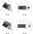
- FIG. 2A is a perspective view illustrating a fuse holder 202 and a fuse device 208 in a first configuration, for example, a primary latching position, in accordance with disclosed embodiments
- FIG. 2B is a top view of the fuse holder 202 in the first configuration, that is, the primary latching position.
- FIG. 2C is a perspective view illustrating the fuse holder 202 and the fuse device 208 in a second configuration, for example, a secondary latching position, in accordance with disclosed embodiments
- FIG. 2D is a top view of the fuse holder 202 in the second configuration, that is, the secondary latching position.
- the fuse holder 202 can include a first holding part 220 and a second holding part 230.
- the first holding part 220 can include a first mounting apparatus 222 at a first end of the first holding part 220, a first joint interface 224 at a second end of the first holding part 220 opposite the first end of the first holding part 220, and a first conductive terminal 226 in between the first end of the first holding part 220 and the second end of the first holding part 220.
- the second holding part 230 can include a second mounting apparatus 232 at a first end of the second holding part 230, a second joint interface 234 at a second end of the second holding part 230 opposite the first end of the second holding part 230, and a second conductive terminal 236 in between the first end of the second holding part 230 and the second end of the second holding part 230.
- the first joint interface 224 can lock with the second joint interface 234 in the primary latching position as illustrated in FIG. 2A and FIG. 2B or in the secondary latching position as illustrated in FIG. 2C and FIG. 2D to create and form a joint device 210. That is, the joint device 210 can be formed by the first joint interface 224 and the second joint interface 234 when latched together.
- the first conductive terminal 226 can be a first distance X1 from the second conductive terminal 236.
- the first conductive terminal 226 can be a second distance X2 from the second conductive terminal 236. As seen in FIG. 2B and FIG. 2C , the second distance X2 can be greater than the first distance X1.
- the joint device 210 can slide along an X axis between the primary latching position and the secondary latching position.
- the second holding part 230 can slide relative to the first holding part 220, including toward or away from and/or into or out of, to move between the primary latching position and the secondary latching position.
- the second joint interface 234 can be unlocked from the first joint interface 224 to move the second joint interface 234 between the primary latching position and the secondary latching position.
- the fuse holder 202 can hold a first fuse device 208 with a first length and pitch in the first configuration, that is, the primary latching position, but can also hold a second fuse device 216 with a second length and pitch in the second configuration, that is, the secondary latching position.
- the second length and pitch can be longer than the first length and pitch, but a different fuse holder is not required.
- the first conductive terminal 226 and the second conductive terminal 236 can accommodate the first fuse device 208, for example, by connecting thereto, when the first joint interface 224 locks with the second joint interface 234 in the primary latching position.
- the first conductive terminal 226 and the second conductive terminal 236 can accommodate the second fuse device 216, for example, by connecting thereto, when the first joint interface 224 locks with the second joint interface 234 in the secondary latching position.
- the fuse holder 202 can be mounted to any desired device as would be known and desired by one of skilled in the art.
- the first mounting apparatus 222 and the second mounting apparatus 232 can be secured to a panel or other device via mounting hardware.
- the first mounting apparatus 222 and/or the second mounting apparatus 232 can include an M6 hole or slot for receiving an M6 stud and/or nut.
- FIG. 3A is a perspective view illustrating a fuse holder 302 and a fuse device 308 in a first configuration, for example, a primary latching position, in accordance with disclosed embodiments
- FIG. 3B is a top view of the fuse holder 302 in the first configuration, that is, the primary latching position.
- FIG. 3C is a perspective view illustrating the fuse holder 302 and the fuse device 308 in a second configuration, for example, a secondary latching position, in accordance with disclosed embodiments
- FIG. 3D is a top view of the fuse holder 302 in the second configuration, that is, the secondary latching position.
- the fuse holder 302 can include a first holding part 320 and a second holding part 330.
- the first holding part 320 can include a first mounting apparatus 322 at a first end of the first holding part 320, a first joint interface 324 at a second end of the first holding part 320 opposite the first end of the first holding part 320, and a first conductive terminal 326 in between the first end of the first holding part 320 and the second end of the first holding part 320.
- the second holding part 330 can include a second mounting apparatus 332 at a first end of the second holding part 330, a second joint interface 334 at a second end of the second holding part 330 opposite the first end of the second holding part 330, and a second conductive terminal 336 in between the first end of the second holding part 330 and the second end of the second holding part 330.
- the first joint interface 324 can lock with the second joint interface 334 in the primary latching position as illustrated in FIG. 3A and FIG. 3B or in the secondary latching position as illustrated in FIG. 3C and FIG. 3D to create and form a joint device 310. That is, the joint device 310 can be formed by the first joint interface 324 and the second joint interface 334 when latched together.
- the first conductive terminal 326 can be a first distance X3 from the second conductive terminal 336.
- the first conductive terminal 326 can be a second distance X4 from the second conductive terminal 336. As seen in FIG. 3B and FIG. 3C , the second distance X4 can be greater than the first distance X3.
- Distances X3 and X4 can be different dimensions than distances X1 and X2.
- fuse holders as disclosed and described herein are not limited to specific dimensions. Rather, a fuse holder can be designed with a first configuration to fit any first fuse device with first specifications and with a second configuration to fit any second fuse device with second specifications.
- the joint device 310 can slide along an X axis between the primary latching position and the secondary latching position.
- the second holding part 330 can slide relative to the first holding part 320, including toward or away from and/or into or out of, to move between the primary latching position and the secondary latching position.
- the second joint interface 334 can be unlocked from the first joint interface 324 to move the second joint interface 334 between the primary latching position and the secondary latching position.
- the fuse holder 302 can hold a first fuse device 308 with a first length and pitch in the first configuration, that is, the primary latching position, but can also hold a second fuse device 316 with a second length and pitch in the second configuration, that is, the secondary latching position.
- the second length can be longer than the first length, but a different fuse holder is not required.
- the first conductive terminal 326 and the second conductive terminal 336 can accommodate the first fuse device 308, for example, by connecting thereto, when the first joint interface 324 locks with the second joint interface 334 in the primary latching position.
- the first conductive terminal 326 and the second conductive terminal 336 can accommodate the second fuse device 316, for example, by connecting thereto, when the first joint interface 324 locks with the second joint interface 334 in the secondary latching position.
- the fuse holder 302 can be mounted to any desired device as would be known and desired by one of skilled in the art.
- the first mounting apparatus 322 and the second mounting apparatus 332 can be secured to a panel or other device via mounting hardware.
- the first mounting apparatus 322 and/or the second mounting apparatus 332 can include an M6 hole or slot for receiving an M6 stud and/or nut.
- FIG. 4A is a top view illustrating a joint device 410 in a primary latching position
- FIG. 5A is a top view illustrating the joint device 410 in a secondary latching position
- FIG. 6A is a top view illustrating the joint device 410 in an unlatched position.
- the joint device 410 can be the same as or similar to the joint device 210 and the joint device 310.
- the joint device 410 can be I-shaped.
- a first joint interface 424 of the joint device 410 can include a first receptacle 428a and a second receptacle 428b, and the second joint interface 434 of the joint device 410 can include a protruding tab 438.
- the protruding tab 438 can lock and/or latch into, onto, and/or through the first receptable 428a.
- the second receptacle 428b can remain empty.
- FIG. 4B is a cross-sectional view of the joint device 410 of FIG. 4A along line H-H and illustrates the protruding tab 438 latched in the first receptacle 428a and the second receptacle 428b being empty in the primary latching position.
- FIG. 4C is a cross-sectional view of the joint device 410 of FIG. 4A along line B-B and illustrates the protruding tab 438 latched in the first receptacle 428a in the latching position.
- FIG. 4D is a cross-sectional view of the joint device 410 of FIG. 4A along line C-C and illustrates the second receptacle 428b being empty in the latching position.
- the protruding tab 438 can lock and/or latch into, onto, and/or through the second receptacle 428b. As such, the first receptacle 428a can remain empty.
- FIG. 5B is a cross-sectional view of the joint device 410 of FIG. 5A along line J-J and illustrates the protruding tab 438 latched in the second receptacle 428b and the first receptacle 428a being empty in the secondary latching position.
- the second joint interface 434 can slide toward or away from and/or into or out of the first joint interface 424, for example, along an X axis.
- at least a portion of the second joint interface 434, including the protruding tab 438, can fit inside of the first joint interface 424 and slide within the first joint interface 424 to move between aligning the protruding tab 438 with the first receptacle 428a and the second receptacle 428b.
- the joint device 410 can be in the unlatched position to slide portions thereof, including the first joint interface 424 and/or the second joint interface 434.
- the first receptacle 428a and the second receptacle 428b can remain empty. That is, in the unlatched position, the protruding tab 438 need not be latched in the first receptacle 428a or the second receptacle 428b.
- FIG. 6A illustrates the second joint interface 434 as being completely outside of the first joint interface.
- the some or all of the second joint interface 434 can be inside of the first joint interface 424 in the unlatched position so long as the protruding tab 438 is outside of and/or unlatched from both the first receptacle 428a and the second receptacle 428b. That is, the unlatched position encompasses a plurality of different configurations of the first joint interface 424 and the second joint interface 434.
- FIG. 6B is a cross-sectional view of the joint device 410 of FIG. 6A along line K-K and illustrates both the first receptacle 428a and the second receptacle 428b being empty and the protruding tab 438 being unlatched therefrom.
- FIG. 6C is a cross-sectional view of the joint device 410 of FIG. 6A along line F-F and illustrates the second receptacle 428b being empty.
- FIG. 6D is a cross-sectional view of the joint device 410 of FIG. 6A along line E-E and illustrates the protruding tab 438 being unlatched from both the first receptacle 428a and the second receptacle 428b.
- FIG. 7 is a flow chart illustrating a method 700 in accordance with disclosed embodiments.
- the method 700 can include locking a first holding part of a fuse holder and a second holding part of the fuse holder in a primary latching position to create a first distance between a first conductive terminal of the first holding part and a second conductive terminal of the second holding part as in 702.
- a first joint interface of the first holding part can be locked with a second joint interface of the second holding part to create a joint device in the primary latching position.
- the method 700 can also include mounting a first fuse device with a first length to the first conductive terminal and the second conductive terminal when the first holding part and the second holding part are locked in the primary latching position.
- the method 700 can include unlocking the first holding part from the second holding part as in 704.
- the method 700 can also include sliding the joint device along an X axis of the fuse holder between the primary latching position and the secondary latching position.
- the method 700 can include sliding the second holding part relative to the first holding part to move between the first latching position and the secondary latching position.
- the method 700 can include locking the first holding part and the second holding part in a secondary latching position to create a second distance between the first conductive terminal and the second conductive terminal as in 706.
- the first joint interface of the first holding part can be locked with the second joint interface of the second holding part to create the joint device in the secondary latching position.
- the method 700 can also include mounting a second fuse device with a second length to the first conductive terminal and the second conductive terminal when the first holding part and the second holding part are locked in the secondary latching position.
- the second distance between the first conductive terminal and the second conductive terminal can be greater than the first distance between the first conductive terminal and the second conductive terminal.
- the second length of the second fuse device can be longer than the first length of the first fuse device.
Landscapes
- Fuses (AREA)
Abstract
A fuse holder can include a first holding part and a second holding part. The first holding part can include a first mounting apparatus, a first joint interface, and a first conductive terminal therebetween, and the second holding part can include a second mounting apparatus, a second joint interface, and a second conductive terminal therebetween. The first joint interface can lock with the second joint interface in a primary latching position or a secondary latching position. When the first joint interface locks with the second joint interface in the primary latching position, the first conductive terminal can be a first distance from the second conductive terminal, but when the first joint interface locks with the second joint interface in the secondary latching position, the first conductive terminal can be a second distance from the second conductive terminal that is greater than the first distance.
Description
- The present disclosure generally relates to fuse holders. More particularly, the present disclosure relates to a fuse holder with a sliding joint.
- A fuse is commonly used as a circuit protection device and can provide electrical connections between sources of electrical power and circuit components to be protected, for example, in automotive and power distribution environments. A fuse holder is a device to hold a fuse in place and can include conductive terminals at ends thereof to connect the fuse between the electrical power and the circuit components to be protected.
- Fuses can be different sizes and have different lengths or pitches. As such, fuse holders known in the art are also different sizes. Indeed, known fuse holders are designed and built to hold fuses of a single size and cannot accommodate fuses of different sizes. For example,
FIG. 1A is a perspective view of afuse holder 102 known in the art holding afuse 108, andFIG. 1B is a perspective view of afuse holder 110 known in the art holding afuse 116. As seen inFIG. 1A ,conductive terminals fuse holder 102 can be connected to ends of thefuse 108 and have a single, fixed distance therebetween that accommodates a length and a pitch of thefuse 108. Similarly, as seen inFIG. 1B ,conductive terminals fuse holder 110 can be connected to ends of thefuse 116 and have a single, fixed distance therebetween that accommodates a length and a pitch of thefuse 116. As such, when thefuse 108 and thefuse 116 have different lengths and pitches, thefuse holder 102 cannot accommodate and hold thefuse 116, and thefuse holder 110 cannot accommodate and hold thefuse 108. - In view of the above, there is a continuing, ongoing need for improved fuse holders.
- This Brief Summary is provided to introduce a selection of concepts in a simplified form that are further described below in the Detailed Description. This Brief Summary is not intended to identify key features or essential features of claimed subject matter or intended as an aid in determining scope of the claimed subject matter.
- The disclosure relates to fuse holder which may comprise a first holding part, a first joint interface, a first conductive terminal, a second holding part, a second joint interface, a second conductive terminal, wherein the first joint interface locks with the second joint interface in a primary latching position or a secondary latching position, wherein when the first joint interface locks with the second joint interface in the primary latching position, the first conductive terminal is a first distance from the second conductive terminal, and wherein when the first joint interface locks with the second joint interface in the secondary latching position, the first conductive terminal is a second distance from the second conductive terminal, the second distance being greater than the first distance.
- The first holding part can include a first mounting apparatus at a first end of the first holding part.
- The first joint interface can be at a second end of the first holding part opposite the first end of the first holding part.
- The first conductive terminal can be between the first end of the first holding part and the second end of the first holding part.
- The second holding part can include a second mounting apparatus at a first end of the second holding part.
- The second joint interface is at a second end of the second holding part opposite the first end of the second holding part.
- The second conductive terminal can be between the first end of the second holding part and the second end of the second holding part.
- The first holding part can include the first joint interface and the first conductive terminal.
- The second holding part can include the second joint interface and the second conductive terminal.
- The second holding part can slide relative to the first holding part to move the second joint interface between the primary latching position and the secondary latching position.
- The second joint interface can be unlocked from the first joint interface to move the second joint interface between the primary latching position and the secondary latching position.
- The first joint interface can lock with the second joint interface to create a joint device.
- The joint device can be I-shaped.
- The joint device can slide along an X axis between the primary latching position and the secondary latching position.
- The first conductive terminal and the second conductive terminal can accommodate a first fuse device with a first length when the first joint interface locks with the second joint interface in the primary latching position, wherein the first conductive terminal and the second conductive terminal can accommodate a second fuse device with a second length when the first joint interface locks with the second joint interface in the secondary latching position, and wherein the second length is longer than the first length.
- The disclosure also relates to method comprising locking a first holding part of a fuse holder and a second holding part of the fuse holder in a primary latching position to create a first distance between a first conductive terminal of the first holding part and a second conductive terminal of the second holding part; unlocking the first holding part from the second holding part; and locking the first holding part and the second holding part in a secondary latching position to create a second distance between the first conductive terminal and the second conductive terminal, the second distance being greater than the first distance.
- After unlocking the second holding part from the first holding part, the second holding part can be slid relative to the first holding part to move between the first latching position and the secondary latching position
- A first fuse device with a first length can be mounted to the first conductive terminal and the second conductive terminal when the first holding part and the second holding part are locked in the primary latching position; and mounting a second fuse device with a second length can be mounted to the first conductive terminal and the second conductive terminal when the first holding part and the second holding part are locked in the secondary latching position, wherein the second length is preferably longer then the first length.
- A first joint interface of the first holding part can be locked with a second joint interface of the second holding part to create a joint device in the primary latching position or the secondary latching position.
- The joint device can be I-shaped.
- The joint device can be slid along an X axis of the fuse holder between the primary latching position and the secondary latching position.
- Other technical features may be readily apparent to one skilled in the art from the following figures, descriptions, and claims.
-
-
FIG. 1A is a perspective view illustrating a fuse holder and a fuse device known in the art. -
FIG. 1B is a perspective view illustrating a fuse holder and a fuse device known in the art. -
FIG. 2A is a perspective view illustrating a fuse holder and a fuse device in accordance with disclosed embodiments. -
FIG. 2B is a top view illustrating a fuse holder in accordance with disclosed embodiments. -
FIG. 2C is a perspective view illustrating a fuse holder and a fuse device in accordance with disclosed embodiments. -
FIG. 2D is a top view illustrating a fuse holder in accordance with disclosed embodiments. -
FIG. 3A is a perspective view illustrating a fuse holder and a fuse device in accordance with disclosed embodiments. -
FIG. 3B is a top view illustrating a fuse holder in accordance with disclosed embodiments. -
FIG. 3C is a perspective view illustrating a fuse holder and a fuse device in accordance with disclosed embodiments. -
FIG. 3D is a top view illustrating a fuse holder in accordance with disclosed embodiments. -
FIG. 4A is a top view illustrating a joint device in accordance with disclosed embodiments. -
FIG. 4B is a cross-sectional view illustrating the joint device ofFIG. 4A along line H-H in accordance with disclosed embodiments. -
FIG. 4C is a cross-sectional view illustrating the joint device ofFIG. 4A along line B-B in accordance with disclosed embodiments. -
FIG. 4D is a cross-sectional view illustrating the joint device ofFIG. 4A along line C-C in accordance with disclosed embodiments. -
FIG. 5A is a top view illustrating a joint device in accordance with disclosed embodiments. -
FIG. 5B is a cross-sectional view illustrating the joint device ofFIG. 5A along line J-J in accordance with disclosed embodiments. -
FIG. 6A is a top view illustrating a joint device in accordance with disclosed embodiments. -
FIG. 6B is a cross-sectional view of the joint device ofFIG. 6A along line K-K in accordance with disclosed embodiments. -
FIG. 6C is a cross-sectional view of the joint device ofFIG. 6A along line F-F in accordance with disclosed embodiments. -
FIG. 6D is a cross-sectional view of the joint device ofFIG. 6A along line E-E in accordance with disclosed embodiments. -
FIG. 7 is a flow chart illustrating a method in accordance with disclosed embodiments. - Exemplary embodiments of a fuse holder with a sliding joint in accordance with the present disclosure will now be described more fully hereinafter with reference made to the accompany drawings. The fuse holder with the sliding joint may, however, be embodied in many different forms and should not be construed as being limited to the embodiments set forth herein. Rather, these embodiments are provided so that this disclosure will convey certain exemplary aspects of a fuse holder with a sliding to those skilled in the art.
- As disclosed herein, a fuse holder can be used to hold, accommodate, and support fuse devices of different sizes. For example, the fuse holder can include a sliding joint that can be latched in different positions to adjust a length of the fuse holder, thereby allowing the fuse holder to fit fuse devices with different lengths and pitches. Advantageously, despite being adjustable, the sliding joint can simultaneously provide stability and stiffness to the fuse holder as needed.
- In some embodiments, the fuse holder as disclosed herein can hold, support, and accommodate fuse devices of any two sizes as would be known and desired by one of skilled in the art, including large body, high voltage fuse devices. For example, in one specific embodiment, in a first configuration, the fuse holder can fit a 500V fuse device with a current range of 60-600A, an overall length of 73mm or 93mm, and a centerline pitch of 60mm or 75mm and, in a second configuration, the fuse holder can fit a 1000V fuse device with a current range of 60-600A, an overall length of 110.5mm, 110.7mm, or 122mm, and a centerline pitch of 91.25mm or 100mm. However, it is to be understood that these specifications are exemplary only and that, in the first configuration, the fuse holder can be designed to fit any first fuse device with first specifications and, in the second configuration, the fuse holder can be designed to fit any second fuse device with second specifications. It is also to be understood that, in some embodiments, the fuse holder can hold, support, and accommodate fuse devices of a plurality of different sizes, such as three different sizes, four different sizes, and more by moving to a plurality of different configurations that is more than two.
-
FIG. 2A is a perspective view illustrating afuse holder 202 and afuse device 208 in a first configuration, for example, a primary latching position, in accordance with disclosed embodiments, andFIG. 2B is a top view of thefuse holder 202 in the first configuration, that is, the primary latching position.FIG. 2C is a perspective view illustrating thefuse holder 202 and thefuse device 208 in a second configuration, for example, a secondary latching position, in accordance with disclosed embodiments, andFIG. 2D is a top view of thefuse holder 202 in the second configuration, that is, the secondary latching position. - As seen, the
fuse holder 202 can include a first holdingpart 220 and asecond holding part 230. Thefirst holding part 220 can include afirst mounting apparatus 222 at a first end of the first holdingpart 220, a firstjoint interface 224 at a second end of the first holdingpart 220 opposite the first end of the first holdingpart 220, and a firstconductive terminal 226 in between the first end of the first holdingpart 220 and the second end of the first holdingpart 220. Similarly, thesecond holding part 230 can include asecond mounting apparatus 232 at a first end of thesecond holding part 230, a secondjoint interface 234 at a second end of thesecond holding part 230 opposite the first end of thesecond holding part 230, and a secondconductive terminal 236 in between the first end of thesecond holding part 230 and the second end of thesecond holding part 230. - The first
joint interface 224 can lock with the secondjoint interface 234 in the primary latching position as illustrated inFIG. 2A and FIG. 2B or in the secondary latching position as illustrated inFIG. 2C and FIG. 2D to create and form ajoint device 210. That is, thejoint device 210 can be formed by the firstjoint interface 224 and the secondjoint interface 234 when latched together. When thejoint device 210 is formed in the primary latching position, that is, the firstjoint interface 224 locks with the secondjoint interface 234 in the primary latching position, the firstconductive terminal 226 can be a first distance X1 from the secondconductive terminal 236. However, when thejoint device 210 is formed in the secondary latching position, that is, the firstjoint interface 224 locks with the secondjoint interface 234 in the secondary latching position, the firstconductive terminal 226 can be a second distance X2 from the secondconductive terminal 236. As seen inFIG. 2B and FIG. 2C , the second distance X2 can be greater than the first distance X1. - To move between the primary latching position and the secondary latching position, the
joint device 210 can slide along an X axis between the primary latching position and the secondary latching position. For example, thesecond holding part 230 can slide relative to the first holdingpart 220, including toward or away from and/or into or out of, to move between the primary latching position and the secondary latching position. In some embodiments, the secondjoint interface 234 can be unlocked from the firstjoint interface 224 to move the secondjoint interface 234 between the primary latching position and the secondary latching position. - The same one
single fuse holder 202 is illustrated inFIGs. 2A-2D , albeit in different configurations. As such, thefuse holder 202 can hold afirst fuse device 208 with a first length and pitch in the first configuration, that is, the primary latching position, but can also hold asecond fuse device 216 with a second length and pitch in the second configuration, that is, the secondary latching position. The second length and pitch can be longer than the first length and pitch, but a different fuse holder is not required. In particular, the firstconductive terminal 226 and the secondconductive terminal 236 can accommodate thefirst fuse device 208, for example, by connecting thereto, when the firstjoint interface 224 locks with the secondjoint interface 234 in the primary latching position. However, the firstconductive terminal 226 and the secondconductive terminal 236 can accommodate thesecond fuse device 216, for example, by connecting thereto, when the firstjoint interface 224 locks with the secondjoint interface 234 in the secondary latching position. - Once configured in the primary latching position or the secondary latching position, the
fuse holder 202 can be mounted to any desired device as would be known and desired by one of skilled in the art. For example, in some embodiments, the first mountingapparatus 222 and thesecond mounting apparatus 232 can be secured to a panel or other device via mounting hardware. In some embodiments, the first mountingapparatus 222 and/or thesecond mounting apparatus 232 can include an M6 hole or slot for receiving an M6 stud and/or nut. -
FIG. 3A is a perspective view illustrating afuse holder 302 and afuse device 308 in a first configuration, for example, a primary latching position, in accordance with disclosed embodiments, andFIG. 3B is a top view of thefuse holder 302 in the first configuration, that is, the primary latching position.FIG. 3C is a perspective view illustrating thefuse holder 302 and thefuse device 308 in a second configuration, for example, a secondary latching position, in accordance with disclosed embodiments, andFIG. 3D is a top view of thefuse holder 302 in the second configuration, that is, the secondary latching position. - As seen, the
fuse holder 302 can include a first holdingpart 320 and asecond holding part 330. Thefirst holding part 320 can include afirst mounting apparatus 322 at a first end of the first holdingpart 320, a firstjoint interface 324 at a second end of the first holdingpart 320 opposite the first end of the first holdingpart 320, and a firstconductive terminal 326 in between the first end of the first holdingpart 320 and the second end of the first holdingpart 320. Similarly, thesecond holding part 330 can include asecond mounting apparatus 332 at a first end of thesecond holding part 330, a secondjoint interface 334 at a second end of thesecond holding part 330 opposite the first end of thesecond holding part 330, and a secondconductive terminal 336 in between the first end of thesecond holding part 330 and the second end of thesecond holding part 330. - The first
joint interface 324 can lock with the secondjoint interface 334 in the primary latching position as illustrated inFIG. 3A and FIG. 3B or in the secondary latching position as illustrated inFIG. 3C and FIG. 3D to create and form ajoint device 310. That is, thejoint device 310 can be formed by the firstjoint interface 324 and the secondjoint interface 334 when latched together. When thejoint device 310 is formed in the primary latching position, that is, the firstjoint interface 324 locks with the secondjoint interface 334 in the primary latching position, the firstconductive terminal 326 can be a first distance X3 from the secondconductive terminal 336. However, when thejoint device 310 is formed in the secondary latching position, that is, the firstjoint interface 324 locks with the secondjoint interface 334 in the secondary latching position, the firstconductive terminal 326 can be a second distance X4 from the secondconductive terminal 336. As seen inFIG. 3B and FIG. 3C , the second distance X4 can be greater than the first distance X3. - Distances X3 and X4 can be different dimensions than distances X1 and X2. As such, fuse holders as disclosed and described herein are not limited to specific dimensions. Rather, a fuse holder can be designed with a first configuration to fit any first fuse device with first specifications and with a second configuration to fit any second fuse device with second specifications.
- To move between the primary latching position and the secondary latching position, the
joint device 310 can slide along an X axis between the primary latching position and the secondary latching position. For example, thesecond holding part 330 can slide relative to the first holdingpart 320, including toward or away from and/or into or out of, to move between the primary latching position and the secondary latching position. In some embodiments, the secondjoint interface 334 can be unlocked from the firstjoint interface 324 to move the secondjoint interface 334 between the primary latching position and the secondary latching position. - The same one
single fuse holder 302 is illustrated inFIGs. 3A-3D , albeit in different configurations. As such, thefuse holder 302 can hold afirst fuse device 308 with a first length and pitch in the first configuration, that is, the primary latching position, but can also hold asecond fuse device 316 with a second length and pitch in the second configuration, that is, the secondary latching position. The second length can be longer than the first length, but a different fuse holder is not required. In particular, the firstconductive terminal 326 and the secondconductive terminal 336 can accommodate thefirst fuse device 308, for example, by connecting thereto, when the firstjoint interface 324 locks with the secondjoint interface 334 in the primary latching position. However, the firstconductive terminal 326 and the secondconductive terminal 336 can accommodate thesecond fuse device 316, for example, by connecting thereto, when the firstjoint interface 324 locks with the secondjoint interface 334 in the secondary latching position. - Once configured in the primary latching position or the secondary latching position, the
fuse holder 302 can be mounted to any desired device as would be known and desired by one of skilled in the art. For example, in some embodiments, the first mountingapparatus 322 and thesecond mounting apparatus 332 can be secured to a panel or other device via mounting hardware. In some embodiments, the first mountingapparatus 322 and/or thesecond mounting apparatus 332 can include an M6 hole or slot for receiving an M6 stud and/or nut. - One embodiment of a sliding joint that includes a joint device in accordance with disclosed embodiments will now be described in more detail.
FIG. 4A is a top view illustrating ajoint device 410 in a primary latching position,FIG. 5A is a top view illustrating thejoint device 410 in a secondary latching position, andFIG. 6A is a top view illustrating thejoint device 410 in an unlatched position. It is to be understood that thejoint device 410 can be the same as or similar to thejoint device 210 and thejoint device 310. - In some embodiments, the
joint device 410 can be I-shaped. In particular, a firstjoint interface 424 of thejoint device 410 can include afirst receptacle 428a and asecond receptacle 428b, and the secondjoint interface 434 of thejoint device 410 can include a protrudingtab 438. - As seen in
FIG. 4A , in the primary latching position, the protrudingtab 438 can lock and/or latch into, onto, and/or through the first receptable 428a. As such, thesecond receptacle 428b can remain empty. -
FIG. 4B is a cross-sectional view of thejoint device 410 ofFIG. 4A along line H-H and illustrates the protrudingtab 438 latched in thefirst receptacle 428a and thesecond receptacle 428b being empty in the primary latching position. -
FIG. 4C is a cross-sectional view of thejoint device 410 ofFIG. 4A along line B-B and illustrates the protrudingtab 438 latched in thefirst receptacle 428a in the latching position. -
FIG. 4D is a cross-sectional view of thejoint device 410 ofFIG. 4A along line C-C and illustrates thesecond receptacle 428b being empty in the latching position. - However, as seen in
FIG. 5A , in the secondary latching position, the protrudingtab 438 can lock and/or latch into, onto, and/or through thesecond receptacle 428b. As such, thefirst receptacle 428a can remain empty. -
FIG. 5B is a cross-sectional view of thejoint device 410 ofFIG. 5A along line J-J and illustrates the protrudingtab 438 latched in thesecond receptacle 428b and thefirst receptacle 428a being empty in the secondary latching position. - To move between the primary latching position and the secondary latching position, the second
joint interface 434 can slide toward or away from and/or into or out of the firstjoint interface 424, for example, along an X axis. In some embodiments, at least a portion of the secondjoint interface 434, including the protrudingtab 438, can fit inside of the firstjoint interface 424 and slide within the firstjoint interface 424 to move between aligning the protrudingtab 438 with thefirst receptacle 428a and thesecond receptacle 428b. - In some embodiments, the
joint device 410 can be in the unlatched position to slide portions thereof, including the firstjoint interface 424 and/or the secondjoint interface 434. For example, as seen inFIG. 6A , in the unlatched position, thefirst receptacle 428a and thesecond receptacle 428b can remain empty. That is, in the unlatched position, the protrudingtab 438 need not be latched in thefirst receptacle 428a or thesecond receptacle 428b. -
FIG. 6A illustrates the secondjoint interface 434 as being completely outside of the first joint interface. However, it is to be understood that embodiments disclosed herein are not so limited and that the some or all of the secondjoint interface 434 can be inside of the firstjoint interface 424 in the unlatched position so long as the protrudingtab 438 is outside of and/or unlatched from both thefirst receptacle 428a and thesecond receptacle 428b. That is, the unlatched position encompasses a plurality of different configurations of the firstjoint interface 424 and the secondjoint interface 434. -
FIG. 6B is a cross-sectional view of thejoint device 410 ofFIG. 6A along line K-K and illustrates both thefirst receptacle 428a and thesecond receptacle 428b being empty and the protrudingtab 438 being unlatched therefrom. -
FIG. 6C is a cross-sectional view of thejoint device 410 ofFIG. 6A along line F-F and illustrates thesecond receptacle 428b being empty. -
FIG. 6D is a cross-sectional view of thejoint device 410 ofFIG. 6A along line E-E and illustrates the protrudingtab 438 being unlatched from both thefirst receptacle 428a and thesecond receptacle 428b. -
FIG. 7 is a flow chart illustrating amethod 700 in accordance with disclosed embodiments. As seen, themethod 700 can include locking a first holding part of a fuse holder and a second holding part of the fuse holder in a primary latching position to create a first distance between a first conductive terminal of the first holding part and a second conductive terminal of the second holding part as in 702. For example, a first joint interface of the first holding part can be locked with a second joint interface of the second holding part to create a joint device in the primary latching position. In some embodiments, themethod 700 can also include mounting a first fuse device with a first length to the first conductive terminal and the second conductive terminal when the first holding part and the second holding part are locked in the primary latching position. - Then, the
method 700 can include unlocking the first holding part from the second holding part as in 704. In some embodiments, after unlocking the second holding part from the first holding part, themethod 700 can also include sliding the joint device along an X axis of the fuse holder between the primary latching position and the secondary latching position. For example, themethod 700 can include sliding the second holding part relative to the first holding part to move between the first latching position and the secondary latching position. - Finally, the
method 700 can include locking the first holding part and the second holding part in a secondary latching position to create a second distance between the first conductive terminal and the second conductive terminal as in 706. For example, the first joint interface of the first holding part can be locked with the second joint interface of the second holding part to create the joint device in the secondary latching position. In some embodiments, themethod 700 can also include mounting a second fuse device with a second length to the first conductive terminal and the second conductive terminal when the first holding part and the second holding part are locked in the secondary latching position. - In some embodiments the second distance between the first conductive terminal and the second conductive terminal can be greater than the first distance between the first conductive terminal and the second conductive terminal. As such, in these embodiments, the second length of the second fuse device can be longer than the first length of the first fuse device.
- As used herein, an element or a step recited in the singular and proceeded with the word "a" or "an" should be understood as not excluding plural elements or steps, unless such exclusion is explicitly recited. Furthermore, references to "one embodiment" of the present disclosure are not intended to be interpreted as excluding the existence of additional embodiments that also incorporate the recited features.
- While the present disclosure makes reference to certain embodiments, numerous modifications, alterations, and changes to the described embodiments are possible without departing from the sphere and scope of the present disclosure, as defined in the appended claims. Accordingly, it is intended that the present disclosure not be limited to the described embodiments, but that it has the full scope defined by the language of the following claims and equivalents thereof.
Claims (15)
- A fuse holder comprising:a first holding part,a first joint interface,a first conductive terminal,a second holding part,a second joint interface,a second conductive terminal,wherein the first joint interface locks with the second joint interface in a primary latching position or a secondary latching position,wherein when the first joint interface locks with the second joint interface in the primary latching position, the first conductive terminal is a first distance from the second conductive terminal, andwherein when the first joint interface locks with the second joint interface in the secondary latching position, the first conductive terminal is a second distance from the second conductive terminal, the second distance being greater than the first distance.
- The fuse holder of claim 1, wherein the first holding part includes a first mounting apparatus at a first end of the first holding part.
- The fuse holder of claim 1 or 2, wherein the first joint interface is at a second end of the first holding part opposite the first end of the first holding part.
- The fuse holder of any of the claims 1-3, wherein the first conductive terminal is in between the first end of the first holding part and the second end of the first holding part.
- The fuse holder of any of the preceding claims, wherein the second holding part includes a second mounting apparatus at a first end of the second holding part.
- The fuse holder of any of the preceding claims, wherein the second joint interface is at a second end of the second holding part opposite the first end of the second holding part.
- The fuse holder of any of the preceding claims, wherein the second conductive terminal is in between the first end of the second holding part and the second end of the second holding part.
- The fuse holder of any of the preceding claims, wherein the first holding part includes the first joint interface and the first conductive terminal.
- The fuse holder according to any of the preceding claims, wherein the second holding part includes the second joint interface and the second conductive terminal.
- The fuse holder of any of the preceding claims, wherein the second holding part slides relative to the first holding part to move the second joint interface between the primary latching position and the secondary latching position.
- The fuse holder of claim 9 or 10, wherein the second joint interface is unlocked from the first joint interface to move the second joint interface between the primary latching position and the secondary latching position.
- The fuse holder of any of the preceding claims, wherein the first joint interface locks with the second joint interface to create a joint device, preferably wherein the joint device is I-shaped and/or wherein the joint device slides along an X axis between the primary latching position and the secondary latching position.
- The fuse holder of any of the preceding claims, wherein the first conductive terminal and the second conductive terminal accommodate a first fuse device with a first length when the first joint interface locks with the second joint interface in the primary latching position, wherein the first conductive terminal and the second conductive terminal accommodate a second fuse device with a second length when the first joint interface locks with the second joint interface in the secondary latching position, and wherein the second length is longer than the first length.
- A method comprising:locking a first holding part of a fuse holder and a second holding part of the fuse holder in a primary latching position to create a first distance between a first conductive terminal of the first holding part and a second conductive terminal of the second holding part;unlocking the first holding part from the second holding part; andlocking the first holding part and the second holding part in a secondary latching position to create a second distance between the first conductive terminal and the second conductive terminal, the second distance being greater than the first distance.
- The method of claim 14, further comprising one or more of the following steps:• after unlocking the second holding part from the first holding part, sliding the second holding part relative to the first holding part to move between the first latching position and the secondary latching position;• mounting a first fuse device with a first length to the first conductive terminal and the second conductive terminal when the first holding part and the second holding part are locked in the primary latching position; and mounting a second fuse device with a second length to the first conductive terminal and the second conductive terminal when the first holding part and the second holding part are locked in the secondary latching position, wherein the second length is longer then the first length;• locking a first joint interface of the first holding part with a second joint interface of the second holding part to create a joint device in the primary latching position or the secondary latching position, and optionally sliding the joint device along an X axis of the fuse holder between the primary latching position and the secondary latching position
Applications Claiming Priority (1)
| Application Number | Priority Date | Filing Date | Title |
|---|---|---|---|
| US18/487,194 US20250125112A1 (en) | 2023-10-16 | 2023-10-16 | Fuse holder with sliding joint |
Publications (1)
| Publication Number | Publication Date |
|---|---|
| EP4542617A1 true EP4542617A1 (en) | 2025-04-23 |
Family
ID=92966837
Family Applications (1)
| Application Number | Title | Priority Date | Filing Date |
|---|---|---|---|
| EP24203750.5A Pending EP4542617A1 (en) | 2023-10-16 | 2024-09-30 | Fuse holder formed of sliding parts |
Country Status (3)
| Country | Link |
|---|---|
| US (1) | US20250125112A1 (en) |
| EP (1) | EP4542617A1 (en) |
| CN (1) | CN119852146A (en) |
Citations (6)
| Publication number | Priority date | Publication date | Assignee | Title |
|---|---|---|---|---|
| US2777118A (en) * | 1953-12-02 | 1957-01-08 | Sundt Engineering Company | Fuse holder |
| DE8436116U1 (en) * | 1984-12-10 | 1985-03-28 | Siemens AG, 1000 Berlin und 8000 München | Fuse carrier |
| US5167541A (en) * | 1991-11-27 | 1992-12-01 | Scosche Industries, Inc. | Fuse holder apparatus with flexible detenting |
| FR2996353A1 (en) * | 2012-10-02 | 2014-04-04 | Renault Sa | Fuse box for receiving fuse for circuit breaker of electrical motor of motor car, has electrical connection elements located inside hollow body, and adjusting unit adjusting spacing separating two electrical connection elements of same pair |
| CN103730300A (en) * | 2012-10-13 | 2014-04-16 | 温州市方为熔断器有限公司 | Fuse support piece (base) with DIN mobile guide rails |
| CN112863971A (en) * | 2021-01-05 | 2021-05-28 | 余姚市超力电力电器有限公司 | Fuse and mounting structure thereof |
-
2023
- 2023-10-16 US US18/487,194 patent/US20250125112A1/en active Pending
-
2024
- 2024-09-30 EP EP24203750.5A patent/EP4542617A1/en active Pending
- 2024-10-15 CN CN202411436431.2A patent/CN119852146A/en active Pending
Patent Citations (6)
| Publication number | Priority date | Publication date | Assignee | Title |
|---|---|---|---|---|
| US2777118A (en) * | 1953-12-02 | 1957-01-08 | Sundt Engineering Company | Fuse holder |
| DE8436116U1 (en) * | 1984-12-10 | 1985-03-28 | Siemens AG, 1000 Berlin und 8000 München | Fuse carrier |
| US5167541A (en) * | 1991-11-27 | 1992-12-01 | Scosche Industries, Inc. | Fuse holder apparatus with flexible detenting |
| FR2996353A1 (en) * | 2012-10-02 | 2014-04-04 | Renault Sa | Fuse box for receiving fuse for circuit breaker of electrical motor of motor car, has electrical connection elements located inside hollow body, and adjusting unit adjusting spacing separating two electrical connection elements of same pair |
| CN103730300A (en) * | 2012-10-13 | 2014-04-16 | 温州市方为熔断器有限公司 | Fuse support piece (base) with DIN mobile guide rails |
| CN112863971A (en) * | 2021-01-05 | 2021-05-28 | 余姚市超力电力电器有限公司 | Fuse and mounting structure thereof |
Also Published As
| Publication number | Publication date |
|---|---|
| CN119852146A (en) | 2025-04-18 |
| US20250125112A1 (en) | 2025-04-17 |
Similar Documents
| Publication | Publication Date | Title |
|---|---|---|
| US11728604B2 (en) | Combination outlet and power distribution unit incorporating the same | |
| US7682205B2 (en) | Multi position electrical connector assembly | |
| US9502836B2 (en) | Socket contact, inter-connector and connector device | |
| US8979559B2 (en) | Lockout tagout plug sleeve | |
| US3933403A (en) | Adaptor for feeding current to electrical contact rails | |
| US11050180B2 (en) | Connector terminal capable of suppressing reduction in connectivity and connector including the same | |
| US6496096B2 (en) | Fuse assembly | |
| BRPI0806235A2 (en) | three position electrical connector assembly | |
| US20210050680A1 (en) | Connector Adapter And Connector Test System | |
| US11099215B2 (en) | Sensor with discrete impedance elements for high voltage connectors | |
| US20240145978A1 (en) | Electrical connector assembly | |
| US20250125112A1 (en) | Fuse holder with sliding joint | |
| US3856375A (en) | Multiple plug device | |
| CN102299452B (en) | Connector device | |
| US12027795B2 (en) | Terminal position assurance and connector | |
| US10771034B2 (en) | Conductive path with noise filter | |
| CN114207952B (en) | Inspection probe device and connector inspection method | |
| US6422897B1 (en) | Shorting contact support for a plug-in projection in an igniter receptacle | |
| EP4465449A2 (en) | Pin connector | |
| CN114944562B (en) | Electric connection module and wire end connector | |
| US20220115825A1 (en) | Adapter mechanism | |
| TWI673918B (en) | Electrical connector | |
| CN222785511U (en) | Connectors, electrical devices and electric vehicles | |
| US20260100537A1 (en) | Electrical connector and electrical connector assembly | |
| US9368915B2 (en) | Contact set for a connection socket |
Legal Events
| Date | Code | Title | Description |
|---|---|---|---|
| PUAI | Public reference made under article 153(3) epc to a published international application that has entered the european phase |
Free format text: ORIGINAL CODE: 0009012 |
|
| STAA | Information on the status of an ep patent application or granted ep patent |
Free format text: STATUS: THE APPLICATION HAS BEEN PUBLISHED |
|
| AK | Designated contracting states |
Kind code of ref document: A1 Designated state(s): AL AT BE BG CH CY CZ DE DK EE ES FI FR GB GR HR HU IE IS IT LI LT LU LV MC ME MK MT NL NO PL PT RO RS SE SI SK SM TR |
|
| STAA | Information on the status of an ep patent application or granted ep patent |
Free format text: STATUS: REQUEST FOR EXAMINATION WAS MADE |
|
| 17P | Request for examination filed |
Effective date: 20251016 |