EP4542615A1 - Operating mechanism, circuit breaker and spd specific disconnector - Google Patents
Operating mechanism, circuit breaker and spd specific disconnector Download PDFInfo
- Publication number
- EP4542615A1 EP4542615A1 EP24306717.0A EP24306717A EP4542615A1 EP 4542615 A1 EP4542615 A1 EP 4542615A1 EP 24306717 A EP24306717 A EP 24306717A EP 4542615 A1 EP4542615 A1 EP 4542615A1
- Authority
- EP
- European Patent Office
- Prior art keywords
- movable contact
- contact bracket
- center plate
- manually
- operating mechanism
- Prior art date
- Legal status (The legal status is an assumption and is not a legal conclusion. Google has not performed a legal analysis and makes no representation as to the accuracy of the status listed.)
- Pending
Links
Images



Classifications
-
- H—ELECTRICITY
- H01—ELECTRIC ELEMENTS
- H01H—ELECTRIC SWITCHES; RELAYS; SELECTORS; EMERGENCY PROTECTIVE DEVICES
- H01H71/00—Details of the protective switches or relays covered by groups H01H73/00 - H01H83/00
- H01H71/10—Operating or release mechanisms
- H01H71/50—Manual reset mechanisms which may be also used for manual release
- H01H71/52—Manual reset mechanisms which may be also used for manual release actuated by lever
- H01H71/526—Manual reset mechanisms which may be also used for manual release actuated by lever the lever forming a toggle linkage with a second lever, the free end of which is directly and releasably engageable with a contact structure
-
- H—ELECTRICITY
- H01—ELECTRIC ELEMENTS
- H01H—ELECTRIC SWITCHES; RELAYS; SELECTORS; EMERGENCY PROTECTIVE DEVICES
- H01H71/00—Details of the protective switches or relays covered by groups H01H73/00 - H01H83/00
- H01H71/10—Operating or release mechanisms
-
- H—ELECTRICITY
- H01—ELECTRIC ELEMENTS
- H01H—ELECTRIC SWITCHES; RELAYS; SELECTORS; EMERGENCY PROTECTIVE DEVICES
- H01H71/00—Details of the protective switches or relays covered by groups H01H73/00 - H01H83/00
- H01H71/02—Housings; Casings; Bases; Mountings
-
- H—ELECTRICITY
- H01—ELECTRIC ELEMENTS
- H01H—ELECTRIC SWITCHES; RELAYS; SELECTORS; EMERGENCY PROTECTIVE DEVICES
- H01H73/00—Protective overload circuit-breaking switches in which excess current opens the contacts by automatic release of mechanical energy stored by previous operation of a hand reset mechanism
- H01H73/02—Details
- H01H73/04—Contacts
Definitions
- the present disclosure relates to the field of electrical engineering, in particular to an operating mechanism, a circuit breaker and a SPD specific disconnector including the operating mechanism.
- SSD SPD specific disconnector
- SPD Sudge protection Device
- an ultra-thin operating mechanism design solution is provided to solve the problems of relative arrangement, strength and movement of the mechanism parts of the small-sized SSD products, so as to ensure that the small-sized SSD products can realize reliable mechanism movement for the required functions.
- an operating mechanism which includes a housing and a moving assembly, wherein the moving assembly includes a manually-operated piece pivotably mounted to the housing and pivotable between an opening position and a closing position; a center plate pivotably mounted to the housing; a transmission assembly, wherein the manually-operated piece is connected with the center plate through the transmission assembly; a movable contact bracket pivotably mounted to the housing and abutting against a first surface of the center plate, wherein the pivot axis of the movable contact bracket coincides with the pivot axis of the center plate; a first torsion spring mounted on a side of the movable contact bracket opposite to the center plate, wherein two ends of the first torsion spring are respectively connected to the movable contact bracket and the center plate, so that pivoting of the center plate can drive the movable contact bracket to pivot and pivoting of the movable contact bracket can drive the center plate to pivot.
- the movable contact bracket moves to the open position when the manually-operated piece moves to the opening position, and moves to the closed position when the manually-operated piece moves to the closing position.
- the respective pivot axes of the manually-operated piece, the center plate and the movable contact bracket are all parallel to a first direction.
- the movable contact bracket and the center plate pass through a plurality of planes which are perpendicular to the first direction.
- the movable contact bracket includes a torsion spring accommodating groove, which includes a base and an arc-shaped protrusion around the pivot axis of the movable contact bracket, wherein the base has a second surface and a third surface which are opposite, the second surface abuts against the first surface, the arc-shaped protrusion extends from the third surface in the first direction, and the first torsion spring is mounted in the torsion spring accommodating groove around the arc-shaped protrusion.
- the movable contact bracket further includes a first cut-off face that cuts off the arc-shaped protrusion and the base, so that the arc-shaped protrusion forms an incomplete annular structure.
- the movable contact bracket is mounted to the housing through a movable contact bracket pivot shaft, and the force acting position of the movable contact bracket pivot shaft on the movable contact bracket is opposite to the first cut-off face relative to the movable contact bracket pivot shaft.
- a total thickness of the moving assembly in the first direction is less than or equal to 7.5 mm.
- the total thickness of the moving assembly in the first direction is less than or equal to 7.3 mm.
- the center plate further includes a boss section protruding from the first surface, and the boss section includes a second cut-off face that conforms with the first cut-off face in shape and is oppositely adjacent to the first cut-off face.
- the first cut-off face is a secant of the incomplete annular structure of the arc-shaped protrusion.
- the transmission assembly includes a lock catch, the lock catch pivotably mounted to a side of the center plate opposite to the movable contact bracket and having a first engaging portion; a connecting rod, two ends of the connecting rod pivotally connected to the manually-operated piece and the lock catch respectively; a trip catch, the trip catch pivotably mounted to the side of the center plate opposite to the movable contact bracket and having a second engaging portion which engages with the first engaging portion.
- the respective pivot axes of the manually-operated piece, the center plate, the lock catch, the trip catch and the movable contact bracket are all parallel to the first direction.
- the operating mechanism is configured to enable the lock catch and the trip catch to be static relative to the center plate through the engagement between the first engaging portion and the second engaging portion.
- the trip catch and the center plate are also connected through a second torsion spring, and the second torsion spring biases the trip catch relative to the center plate, so that the first engaging portion and the second engaging portion are abutted and engaged.
- a relatively static assembly is formed by the center plate, the lock catch and the trip catch, wherein the manually-operated piece, the connecting rod, the center plate and the relatively static assembly can form a four-bar linkage, so that when the manually-operated piece moves to the opening position, the movable contact bracket moves to the open position, and when the manually-operated piece moves to the closing position, the movable contact bracket moves to the closed position.
- the four-bar linkage including the manually-operated piece, the connecting rod and the relatively static assembly passes through the position of dead point.
- the connecting rod has two sections that are angled with respect to each other.
- the trip catch is further provided with an extended end adjacent to the movable contact bracket, and a gap is provided between the extended end and the movable contact bracket in a plane perpendicular to the first direction.
- the operating mechanism further includes an open spring, wherein two ends of the open spring are respectively connected to the center plate and the housing, and the open spring is compressed when the manually-operated piece is in the closing position.
- the trip catch and the lock catch respectively abut against a fourth surface and a fifth surface of the center plate, and respective planes where the fourth surface and the fifth surface are located are spaced from each other and are both perpendicular to the first direction.
- the fourth surface is further away from the first surface than the fifth surface.
- a circuit breaker is also provided, wherein the circuit breaker includes the operating mechanism described in any one of the above embodiments.
- the maximum thickness of the circuit breaker in the first direction is between 8.8 mm and 9.2 mm.
- a SPD specific disconnector is also provided, wherein the SPD specific disconnector includes the operating mechanism described in any one of the above embodiments.
- the maximum thickness of the SPD specific disconnector in the first direction is between 8.8 mm and 9.2 mm.
- the direction in which the pivot axis of the manually-operated piece 2 is located is designated as the first direction.
- the operating mechanism includes a housing 1 and a moving assembly.
- the moving assembly includes a manually-operated piece 2, a center plate 3, a movable contact bracket 4 and a transmission assembly. Both the manually-operated piece 2 and the center plate 3 are pivotably mounted to the housing 1, and the respective pivot axes of the manually-operated piece 2 and the center plate 3 are parallel to each other, that is, parallel to the first direction.
- the manually-operated piece 2 further includes an operating handle 21 protruding from the housing, so that the manually-operated piece 2 can be pivoted about its pivot axis by swinging the operating handle 21.
- the housing 1 is further configured to limit the swing range of the operating handle 21 so that the manually-operated piece 2 can only move between an opening position and a closing position.
- Fig. 1 shows the manually-operated piece 2 in the opening position
- fig. 2 shows the manually-operated piece 2 in the closing position.
- the movable contact bracket 4 is also pivotably mounted to the housing 1 and pivots around an axis the same with the center plate 3.
- the movable contact bracket 4 is mounted against one side of the center plate 3, and is connected with the center plate 3 through a first torsion spring 71 (as shown in fig. 3b ), so that the pivoting of the center plate 3 can drive the movable contact bracket 4 to pivot and the pivoting of the movable contact bracket 4 can drive the center plate 3 to pivot.
- a movable contact 43 is installed at an end of the movable contact bracket 4, as shown in fig. 3b . The contact and separation between the movable contact 43 and the stationary contact 61 realize the on-off of the circuit.
- the transmission assembly includes a lock catch 51, a trip catch 52, and a connecting rod 53 to connect the manually-operated piece 2 with the center plate 3 in a transmission manner. That is, the movement of the manually-operated piece 2 can be transmitted to the center plate 3 through the transmission assembly, and vice versa, i.e., the movement of the center plate 3 can be transmitted to the manually-operated piece 2 through the transmission assembly, which will be described in detail later.
- the pivoting of the manually-operated piece 2 can drive the pivoting of the movable contact bracket 4, and the pivoting of the movable contact bracket 4 can also drive the pivoting of the manually-operated piece 2.
- the movable contact bracket 4 drives the movable contact 43 to separate from the stationary contact 61.
- the movable contact bracket 4 moves to the closed position, and at the closed position, the movable contact 43 keeps in contact with the stationary contact 61. Therefore, the on-off operation of the movable contact 43 and the stationary contact 61 can be controlled by the operating handle 2.
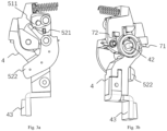
- Figs. 3a and 3b show the assembly schematic diagrams of some components of the operating mechanism according to the present disclosure from two perspectives.
- the lock catch 51 is pivotably mounted to a side of the center plate 3 opposite to the movable contact bracket 4 and has a first engaging portion 511.
- the trip catch 52 is pivotably mounted to the side of the center plate opposite to the movable contact bracket 4, and the trip catch 52 has a second engaging portion 521 engaged with the first engaging portion 511.
- the first engaging portion 511 and the second engaging portion 521 can engage with each other so that the lock catch 51 and the trip catch 52 can be static relative to the center plate 3.
- the respective pivot axis directions of the lock catch 51 and the trip catch 52 are both parallel to the first direction.
- first engaging portion 511 and the second engaging portion 521 may have complementary hook structures.
- first engaging portion 511 and the second engaging portion 521 may also have clamping structures, overlapping structures, keyway structures and other engaging structures that can be conceived by those skilled in the art.
- trip catch 52 and the center plate 3 are also connected by a second torsion spring 72 to bias the trip catch 52 to the position where it engages with the lock catch 51, which further ensures that the trip catch 52 and the lock catch are engaged through the first engaging portion 511 and the second engaging portion 521, and is also beneficial for the trip catch 52 to return to the original position after the trip catch 52 and the lock catch 51 are disengaged, so as to keep the smooth closing of the stationary contact and the movable contact.
- the transmission assembly further includes a connecting rod 53. As shown in figs. 1 and 2 , two ends of the connecting rod 53 are pivotally connected to the manually-operated piece 2 and the lock catch 51, respectively.
- the connecting rod 53 may have two sections angled with respect to teach other to avoid other mechanisms or components in the housing, thereby preventing interference and further improving space compactness.
- the trip catch 52 and the lock catch 51 always keep engaged, that is, the trip catch 52 and the lock catch 51 always keep static relative to the center plate 3, so the distance between the point of connection between the connecting rod 53 and the lock catch 51 and the pivot axis of the center plate 3 is constant. Therefore, the center plate 3, the lock catch 51 and the trip catch 52 form a relatively static assembly, so that the manually-operated piece 2, the connecting rod 53 and the relatively static assembly formed by the center plate 3, the lock catch 51 and the trip catch 52 form a four-bar linkage. That is, both the manually-operated piece 2 and the center plate 3 are pivotably fixed, while the two ends of the connecting rod 53 are pivot connection points, and through the four-bar linkage, the manually-operated piece 2 drives the center plate 3 to pivot.
- the above-mentioned four-bar linkage is configured to pass through the dead point position.
- the connection point between the manually-operated piece 2 and the connecting rod 53, the connection point between the manually-operated piece 2 and the lock catch 51, and the pivot center point of the manually-operated piece 2 are in a straight line.
- the movable contact bracket 4 cannot easily move from the closed position to the open position due to the configuration of the dead point position, thus ensuring the long-term contact between the movable contact 43 and the stationary contact 61.
- an actuator 62 In order to realize the separation of the movable contact 43 from the stationary contact 61, an actuator 62 needs to be provided, which can be, for example, an electromagnetic coil, a pneumatic cylinder, a hydraulic cylinder, etc., and has an actuating end that moves in a direction perpendicular to the first direction. The actuating end can make the movable contact bracket 4 have kinetic energy to realize the opening movement.
- an actuator 62 can be, for example, an electromagnetic coil, a pneumatic cylinder, a hydraulic cylinder, etc., and has an actuating end that moves in a direction perpendicular to the first direction.
- the actuating end can make the movable contact bracket 4 have kinetic energy to realize the opening movement.
- the existence of the dead point makes it difficult for the movable contact bracket 4 to move to the open position, it is necessary to disengage the first engaging portion 511 from the second engaging portion 521, so that the four-bar linkage changes into a five-bar linkage.
- the trip catch 52 is further provided with an extended end 522, which can be arranged between the free end of the actuator 62 and the movable contact bracket 4.
- the free end can strike the extended end 522, so that the trip catch 52 can pivot around its pivot axis away from the lock catch 51, for example, the first engaging portion 511 is disengaged from the second engaging portion 521, so that the lock catch 51 can pivot relative to the center plate 3.
- the manually-operated piece 2, the connecting rod 53, the lock catch 51, and the center plate 3 form a five-bar linkage.
- the housing 1 according to the present disclosure has a maximum thickness between 8.8 and 9.2 mm in the first direction.
- the maximum thickness of the housing refers to the maximum distance between any two points on the housing in the first direction measured from the outside of the housing. Such thickness greatly reduces the volume of the product according to the present disclosure, so that the product can be more easily installed in a narrow installation space.
- the total thickness of the moving assembly (i.e., the manually-operated piece 2, the center plate 3, the trip catch 52, the lock catch 51, the movable contact bracket 4, the first torsion spring 71 and the connecting rod 53) in the first direction may be less than or equal to 7.6 mm, or less than or equal to 7.5 mm, or less than or equal to 7.4 mm, or less than or equal to 7.3 mm, or less than or equal to 7.2 mm, or less than or equal to 7.1 mm, or less than or equal to 7.0 mm.
- the total thickness of the moving assembly in the first direction refers to the total thickness of the moving assembly in the assembled state, that is, the maximum distance between any two points in the moving assembly in the first direction.
- Fig. 4a is a cross-sectional view taken along section line N-N in fig. 4b
- fig. 4b shows a schematic plan view of the structure in figs. 3a and 3b
- fig. 4c is an enlarged schematic view of the structure in the circle in fig. 4a
- fig. 4d is an enlarged schematic view of the structure in the rectangle in fig. 4b .
- the movable contact bracket 4, the center plate 3, the lock catch 51 and the snap catch 52 pass through a plurality of planes perpendicular to the first direction, that is, the extension interval of these components in the first direction intersect, thereby making full use of the space and reducing the thickness of the moving assembly in the first direction, so as to realize the above-mentioned total thickness range of the moving assembly.
- the operating mechanism according to the present disclosure may further include an open spring 73, the two ends of which are respectively connected to the center plate 3 and the housing 1.
- the open spring 73 When the manually-operated piece 2 is in the closing position, that is, when the movable contact bracket 4 is in the closed position, the open spring 73 is compressed, and when the movable contact bracket 4 moves from the closed position to the open position, the open spring 73 releases elastic potential energy to further accelerate the movement of the open spring 73, which is beneficial for further shortening the time for opening and further improving the safety performance.
- the housing further includes a first rib 11 and a second rib 12.
- a first rib is arranged between the manually-operated piece 2 and the center plate 3 as well as the movable contact bracket 4 for airflow barrier.
- the second rib 12 is arranged adjacent to the movable contact bracket 4, as shown in fig. 2 , and is used for limiting and blocking the movable contact bracket 4, absorbing the opening energy of the operating mechanism, and preventing the movable contact bracket from rebounding excessively and thus the breakdown of the contact.
- Fig. 5 shows a movable contact bracket 4 according to an embodiment of the present disclosure.
- the movable contact bracket 4 is mounted to the housing 1 through a movable contact bracket pivot shaft 42 (shown in fig. 3b ), and further includes a torsion spring accommodating groove 41.
- the torsion spring accommodating groove 41 includes a base 411 and an arc-shaped protrusion 412 surrounding the movable contact bracket pivot shaft 42.
- the base has a second surface 82 and a third surface 83 which are opposite to each other.
- the second surface 82 is used for abutting against the first surface 81 of the center plate 3, as shown in fig. 4c .
- the arc-shaped protrusion 412 extends from the third surface 83 in the first direction.
- the first torsion spring 71 is installed, surrounding the arc-shaped protrusion 412, in the torsion spring accommodating groove 41 to prevent the first torsion spring 71 from being detached from the operating mechanism, and the arc-shaped protrusion 412 can exert an abutting force on the first torsion spring 71, so that the first torsion spring 71 can be balanced in force.
- the movable contact bracket 4 further includes a first cut-off face 86 which cuts off the arc-shaped protrusion 412 and the base 411, so that the arc-shaped protrusion 412 forms an incomplete annular structure.
- the position of the first cut-off face 86 needs to be designed accurately. Specifically, the extreme stress point (black dot marked in fig. 4b ) of the movable contact bracket pivot shaft 42 on the movable contact bracket 4 is opposite to the first cut-off face 86 with respect to the movable contact bracket pivot shaft 42. As shown in fig. 4b , force analysis is performed on the movable contact bracket 4.
- the movable contact bracket 4 is subjected to force Fl from the first torsion spring, and when it is closed, it is subjected to force F2 from the stationary contact 61 (not shown). In order to balance these two forces, the movable contact bracket 4 is further subjected to the stress from the movable contact bracket pivot shaft 42. Therefore, the acting position of force from the movable contact bracket pivot shaft 42 on the movable contact bracket 4 can be set.
- the stressed position can be set to avoid the first cut-off face 86 (where the strength is weak), that is, the stressed position and the first cut-off face 86 are located on either side of the movable contact bracket pivot shaft 42 respectively. Therefore, although a cut-off face exists, the strength of the movable contact bracket 4 will not be affected.
- the provision of the cut-off face reserves more space for the center plate 3, so that the center plate 3 can be set thicker in the reserved space to ensure the strength and machinability of the center plate.
- Figs. 6a and 6b respectively show schematic perspective views of the center plate 3 according to the present disclosure from two perspectives.
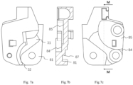
- Figs. 7a-7c show plan views of the center plate according to the present disclosure, among which, fig. 7a is a plan view of a first side of the center plate, fig. 7b is a cross-sectional view taken along section line M-M in fig. 7c, and fig. 7c is a plan view of a second side of the center plate.
- Fig. 6a shows a first side of the center plate 3, on which a first surface 81 is provided, and the movable contact bracket 4 is mounted against the first surface 81.
- the center plate 3 further includes a boss section 31 protruding from the first surface 81, and the boss section 31 includes a second cut-off face 87.
- the second cut-off face 87 and the first cut-off face 86 conform with each other in shape, and the two faces are set oppositely adjacent, that is, the boss section 31 is set oppositely adjacent to the arc-shaped protrusion 412, as shown in figs. 4b and 4d .
- the arrangement of the boss section 31 increases the thickness of the center plate 3 where the boss section 31 is located. Without the boss section 31 having the second cut-off face 87, it is possible that the first surface 81 is almost in the same plane as the fourth surface 84 (to be described later), so that the center plate 3 would not be manufacturable, and even if it is manufactured, it would be unusable because of the extremely low strength.
- the first side of the center plate 3 can further be provided with an arc-shaped section 32, which arc-shaped section forms a complete circular periphery with the movable contact bracket 4, as shown in fig. 4b , so as to surround the first torsion spring, further ensuring the firm installation of the first torsion spring 71 and preventing accidental detachment.
- the first cut-off face 86 is a secant of the incomplete annular structure of the arc-shaped protrusion 412, that is, the first cut-off face 86 is a plane, and thus the second cut-off face 87 is also a plane, which is beneficial for manufacture and assembly.
- the center plate 3 further includes a first stop portion 33 and a second stop portion 34, which are respectively used to limit the movement range of the lock catch 51 and the trip catch 52. Providing the two stop portions on the center plate makes use of the space to a further extent, making the structure more compact and conducive to further reducing the total thickness of the moving assembly in the first direction.
- the second side of the center plate 3 can be provided with a fourth surface 84 and a fifth surface 85.
- the trip catch 52 is mounted against the fourth surface 84 of the center plate 3, and the lock catch 51 is mounted against the fifth surface 85 of the center plate 3.
- the respective planes where the fourth surface 84 and the fifth surface 85 are located are spaced away from each other and are both perpendicular to the first direction.
- the fourth surface 84 is further away from the first surface 81 than the fifth surface 85, as shown in the cross-sectional views of figs. 4c and 7b .
- the strength of the lock catch 51 needs to be greater than that of the trip catch 52, so that the arrangement of the fifth surface 85 closer to the first surface 81 than the fourth surface 84 reserves more space for the lock catch 51, so that the lock catch 51 can be set thicker to ensure the strength.
- the product including the above operating mechanism according to the present disclosure can be a circuit breaker, especially a micro circuit breaker (MCB), and can also be a SPD specific disconnector (SSD).
- MB micro circuit breaker
- SSD SPD specific disconnector
- the product according to the present disclosure has the small-sized part structures with high strength that meets the requirements regarding short circuit and aftercurrent, while resisting lightning current
Landscapes
- Driving Mechanisms And Operating Circuits Of Arc-Extinguishing High-Tension Switches (AREA)
Abstract
According to the present disclosure, an operating mechanism is provided, which comprises a housing and a moving assembly. The moving assembly comprises a manually-operated piece, a center plate, a transmission assembly, a movable contact bracket and a first torsion spring. Two ends of the first torsion spring are respectively connected to the movable contact bracket and the center plate, so that the pivoting of the center plate can drive the movable contact bracket to pivot and the pivoting of the movable contact bracket can drive the center plate to pivot. Through the transmission assembly and the center plate, the movable contact bracket moves to the open position when the manually-operated piece moves to the opening position, and moves to the closed position when the manually-operated piece moves to the closing position, the movable contact bracket further comprises a first cut-off face that cuts off an arc-shaped protrusion and a base, so that the arc-shaped protrusion forms an incomplete annular structure, the movable contact bracket is mounted to the housing through a movable contact bracket pivot shaft, and the extreme point of the stress of the movable contact bracket pivot shaft on the movable contact bracket is opposite to the first cut-off face relative to the movable contact bracket pivot shaft.
Description
- The present disclosure relates to the field of electrical engineering, in particular to an operating mechanism, a circuit breaker and a SPD specific disconnector including the operating mechanism.
- In order to increase the safety of electricity use, SSD (SPD specific disconnector) and SPD (Surge protection Device) are often added to some circuits, the two connected in series in the electrical circuit. SPD can resist lightning strike, and SSD provides short-circuit protection and aftercurrent protection for SPD.
- In addition, in society nowadays, it is a development trend for the integration and miniaturization of low-voltage electrical products, which requires the size of SSD products and SPD products to be reduced, which then requires the size of each component in a product to be smaller and smaller. There is a need to design small-sized part structures with high strength that meets the requirements regarding short circuit and aftercurrent, while resisting lightning current.
- It is difficult to achieve the relative positioning of the internal parts of a small-sized mechanism assembly, and it is even more difficult to achieve the strength design of parts that meets the small size. According to the present disclosure, an ultra-thin operating mechanism design solution is provided to solve the problems of relative arrangement, strength and movement of the mechanism parts of the small-sized SSD products, so as to ensure that the small-sized SSD products can realize reliable mechanism movement for the required functions.
- According to the present disclosure, at least the shortcomings existing in the prior art is solved. According to the present disclosure, an operating mechanism is provided, which includes a housing and a moving assembly, wherein the moving assembly includes a manually-operated piece pivotably mounted to the housing and pivotable between an opening position and a closing position; a center plate pivotably mounted to the housing; a transmission assembly, wherein the manually-operated piece is connected with the center plate through the transmission assembly; a movable contact bracket pivotably mounted to the housing and abutting against a first surface of the center plate, wherein the pivot axis of the movable contact bracket coincides with the pivot axis of the center plate; a first torsion spring mounted on a side of the movable contact bracket opposite to the center plate, wherein two ends of the first torsion spring are respectively connected to the movable contact bracket and the center plate, so that pivoting of the center plate can drive the movable contact bracket to pivot and pivoting of the movable contact bracket can drive the center plate to pivot.
- Through the transmission assembly and the center plate, the movable contact bracket moves to the open position when the manually-operated piece moves to the opening position, and moves to the closed position when the manually-operated piece moves to the closing position. The respective pivot axes of the manually-operated piece, the center plate and the movable contact bracket are all parallel to a first direction. The movable contact bracket and the center plate pass through a plurality of planes which are perpendicular to the first direction.
- The movable contact bracket includes a torsion spring accommodating groove, which includes a base and an arc-shaped protrusion around the pivot axis of the movable contact bracket, wherein the base has a second surface and a third surface which are opposite, the second surface abuts against the first surface, the arc-shaped protrusion extends from the third surface in the first direction, and the first torsion spring is mounted in the torsion spring accommodating groove around the arc-shaped protrusion.
- The movable contact bracket further includes a first cut-off face that cuts off the arc-shaped protrusion and the base, so that the arc-shaped protrusion forms an incomplete annular structure. The movable contact bracket is mounted to the housing through a movable contact bracket pivot shaft, and the force acting position of the movable contact bracket pivot shaft on the movable contact bracket is opposite to the first cut-off face relative to the movable contact bracket pivot shaft.
- According to some embodiments of the present disclosure, a total thickness of the moving assembly in the first direction is less than or equal to 7.5 mm.
- According to some embodiments of the present disclosure, the total thickness of the moving assembly in the first direction is less than or equal to 7.3 mm.
- According to some embodiments of the present disclosure, the center plate further includes a boss section protruding from the first surface, and the boss section includes a second cut-off face that conforms with the first cut-off face in shape and is oppositely adjacent to the first cut-off face.
- According to some embodiments of the present disclosure, in a cross section perpendicular to the first direction, the first cut-off face is a secant of the incomplete annular structure of the arc-shaped protrusion.
- According to some embodiments of the present disclosure, the transmission assembly includes a lock catch, the lock catch pivotably mounted to a side of the center plate opposite to the movable contact bracket and having a first engaging portion; a connecting rod, two ends of the connecting rod pivotally connected to the manually-operated piece and the lock catch respectively; a trip catch, the trip catch pivotably mounted to the side of the center plate opposite to the movable contact bracket and having a second engaging portion which engages with the first engaging portion.
- The respective pivot axes of the manually-operated piece, the center plate, the lock catch, the trip catch and the movable contact bracket are all parallel to the first direction.
- The operating mechanism is configured to enable the lock catch and the trip catch to be static relative to the center plate through the engagement between the first engaging portion and the second engaging portion.
- According to some embodiments of the present disclosure, the trip catch and the center plate are also connected through a second torsion spring, and the second torsion spring biases the trip catch relative to the center plate, so that the first engaging portion and the second engaging portion are abutted and engaged.
- According to some embodiments of the present disclosure, in a state that the first engaging portion and the second engaging portion are engaged, a relatively static assembly is formed by the center plate, the lock catch and the trip catch, wherein the manually-operated piece, the connecting rod, the center plate and the relatively static assembly can form a four-bar linkage, so that when the manually-operated piece moves to the opening position, the movable contact bracket moves to the open position, and when the manually-operated piece moves to the closing position, the movable contact bracket moves to the closed position.
- According to some embodiments of the present disclosure, during the movement of the movable contact bracket from the open position to the closed position, the four-bar linkage including the manually-operated piece, the connecting rod and the relatively static assembly passes through the position of dead point.
- According to some embodiments of the present disclosure, the connecting rod has two sections that are angled with respect to each other.
- According to some embodiments of the present disclosure, the trip catch is further provided with an extended end adjacent to the movable contact bracket, and a gap is provided between the extended end and the movable contact bracket in a plane perpendicular to the first direction.
- According to some embodiments of the present disclosure, when the extended end is actuated, the trip catch pivots relative to the center plate, so that the first engaging portion and the second engaging portion are disengaged, and the manually-operated piece, the connecting rod, the lock catch and the center plate can form a five-bar linkage, and the extended end can strike the movable contact bracket so that the movable contact bracket moves toward the open position.
- According to some embodiments of the present disclosure, the operating mechanism further includes an open spring, wherein two ends of the open spring are respectively connected to the center plate and the housing, and the open spring is compressed when the manually-operated piece is in the closing position.
- According to some embodiments of the present disclosure, the trip catch and the lock catch respectively abut against a fourth surface and a fifth surface of the center plate, and respective planes where the fourth surface and the fifth surface are located are spaced from each other and are both perpendicular to the first direction.
- According to some embodiments of the present disclosure, the fourth surface is further away from the first surface than the fifth surface.
- According to the present disclosure, a circuit breaker is also provided, wherein the circuit breaker includes the operating mechanism described in any one of the above embodiments.
- According to some embodiments of the present disclosure, the maximum thickness of the circuit breaker in the first direction is between 8.8 mm and 9.2 mm.
- According to the present disclosure, a SPD specific disconnector is also provided, wherein the SPD specific disconnector includes the operating mechanism described in any one of the above embodiments.
- According to some embodiments of the present disclosure, the maximum thickness of the SPD specific disconnector in the first direction is between 8.8 mm and 9.2 mm.
-
-
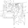
Fig. 1 shows a schematic plan view of an operating mechanism according to the present disclosure, in which the movable contact bracket is in the open position; -
Fig. 2 shows a schematic plan view of the operating mechanism according to the present disclosure, in which the movable contact bracket is in the closed position; -
Figs. 3a and 3b show assembly schematic diagrams of some components of the operating mechanism according to the present disclosure from two perspectives; -
Fig. 4a is a cross-sectional view taken along section line N-N infig. 4b, and fig. 4b shows a schematic plan view of the structure infigs. 3a and 3b ,fig. 4c is an enlarged schematic view of the structure in the circle infig. 4a , andfig. 4d is an enlarged schematic view of the structure in the rectangle infig. 4b ; -
Fig. 5 shows a schematic perspective view of the movable contact bracket according to the present disclosure; -
Figs. 6a and 6b respectively show schematic perspective views of a center plate according to the present disclosure from two perspectives; -
Figs. 7a-7c show plan views of the center plate according to the present disclosure, among which,fig. 7a is a plan view of a first side of the center plate,fig. 7b is a cross-sectional view taken along section line M-M infig. 7c, and fig. 7c is a plan view of a second side of the center plate. - In order to make the purpose, solutions and advantages of the technical solutions of the present disclosure clearer, the technical solutions of the embodiments of the present disclosure will be described clearly and completely with the accompanying drawings of specific embodiments of the present disclosure. Unless otherwise specified, the terms used herein have the ordinary meaning in the art. In the drawings, the same reference numerals represent the same parts.
- In the description of the present disclosure, it should be noted that unless otherwise specified and limited, terms "mounted", "in connection" and "connected" should be broadly understood. For example, they can refer to fixed connection, detachable connection or integrated connection; they can refer to mechanical connection or electrical connection; they can refer to direct connection, indirect connection through an intermediate medium, and inner connection between two elements. For those skilled in the art, the specific meanings of the above terms in the present disclosure can be understood according to specific situations.
- For convenience of description, the direction in which the pivot axis of the manually-operated
piece 2 is located is designated as the first direction. - The operating mechanism according to the present disclosure, as shown in
figs. 1 and2 , includes ahousing 1 and a moving assembly. The moving assembly includes a manually-operatedpiece 2, acenter plate 3, amovable contact bracket 4 and a transmission assembly. Both the manually-operatedpiece 2 and thecenter plate 3 are pivotably mounted to thehousing 1, and the respective pivot axes of the manually-operatedpiece 2 and thecenter plate 3 are parallel to each other, that is, parallel to the first direction. The manually-operatedpiece 2 further includes anoperating handle 21 protruding from the housing, so that the manually-operatedpiece 2 can be pivoted about its pivot axis by swinging theoperating handle 21. In addition, thehousing 1 is further configured to limit the swing range of the operating handle 21 so that the manually-operatedpiece 2 can only move between an opening position and a closing position.Fig. 1 shows the manually-operatedpiece 2 in the opening position andfig. 2 shows the manually-operatedpiece 2 in the closing position. - The
movable contact bracket 4 is also pivotably mounted to thehousing 1 and pivots around an axis the same with thecenter plate 3. Themovable contact bracket 4 is mounted against one side of thecenter plate 3, and is connected with thecenter plate 3 through a first torsion spring 71 (as shown infig. 3b ), so that the pivoting of thecenter plate 3 can drive themovable contact bracket 4 to pivot and the pivoting of themovable contact bracket 4 can drive thecenter plate 3 to pivot. Amovable contact 43 is installed at an end of themovable contact bracket 4, as shown infig. 3b . The contact and separation between themovable contact 43 and thestationary contact 61 realize the on-off of the circuit. - The transmission assembly includes a
lock catch 51, atrip catch 52, and a connectingrod 53 to connect the manually-operatedpiece 2 with thecenter plate 3 in a transmission manner. That is, the movement of the manually-operatedpiece 2 can be transmitted to thecenter plate 3 through the transmission assembly, and vice versa, i.e., the movement of thecenter plate 3 can be transmitted to the manually-operatedpiece 2 through the transmission assembly, which will be described in detail later. - Therefore, through the
center plate 3 and the transmission assembly, the pivoting of the manually-operatedpiece 2 can drive the pivoting of themovable contact bracket 4, and the pivoting of themovable contact bracket 4 can also drive the pivoting of the manually-operatedpiece 2. As shown infig. 1 , when the manually-operatedpiece 2 moves to the opening position, themovable contact bracket 4 moves to the open position, and at the open position, themovable contact bracket 4 drives themovable contact 43 to separate from thestationary contact 61. As shown infig. 2 , when the manually-operatedpiece 2 moves to the closing position, themovable contact bracket 4 moves to the closed position, and at the closed position, themovable contact 43 keeps in contact with thestationary contact 61. Therefore, the on-off operation of themovable contact 43 and thestationary contact 61 can be controlled by theoperating handle 2. - Next, the structures of the
center plate 3, themovable contact bracket 4 and the transmission assembly are introduced in detail. -
Figs. 3a and 3b show the assembly schematic diagrams of some components of the operating mechanism according to the present disclosure from two perspectives. Specifically, as shown infig. 3a , thelock catch 51 is pivotably mounted to a side of thecenter plate 3 opposite to themovable contact bracket 4 and has a firstengaging portion 511. Thetrip catch 52 is pivotably mounted to the side of the center plate opposite to themovable contact bracket 4, and thetrip catch 52 has a secondengaging portion 521 engaged with the first engagingportion 511. The firstengaging portion 511 and the secondengaging portion 521 can engage with each other so that thelock catch 51 and thetrip catch 52 can be static relative to thecenter plate 3. The respective pivot axis directions of thelock catch 51 and thetrip catch 52 are both parallel to the first direction. For example, as shown infig. 3a , the first engagingportion 511 and the secondengaging portion 521 may have complementary hook structures. In addition, the first engagingportion 511 and the secondengaging portion 521 may also have clamping structures, overlapping structures, keyway structures and other engaging structures that can be conceived by those skilled in the art. - In addition, the
trip catch 52 and thecenter plate 3 are also connected by asecond torsion spring 72 to bias thetrip catch 52 to the position where it engages with thelock catch 51, which further ensures that thetrip catch 52 and the lock catch are engaged through the first engagingportion 511 and the secondengaging portion 521, and is also beneficial for thetrip catch 52 to return to the original position after thetrip catch 52 and thelock catch 51 are disengaged, so as to keep the smooth closing of the stationary contact and the movable contact. - The transmission assembly further includes a connecting
rod 53. As shown infigs. 1 and2 , two ends of the connectingrod 53 are pivotally connected to the manually-operatedpiece 2 and thelock catch 51, respectively. The connectingrod 53 may have two sections angled with respect to teach other to avoid other mechanisms or components in the housing, thereby preventing interference and further improving space compactness. - When the manually-operated
piece 2 drives thecenter plate 3 to pivot through the transmission assembly, thetrip catch 52 and thelock catch 51 always keep engaged, that is, thetrip catch 52 and thelock catch 51 always keep static relative to thecenter plate 3, so the distance between the point of connection between the connectingrod 53 and thelock catch 51 and the pivot axis of thecenter plate 3 is constant. Therefore, thecenter plate 3, thelock catch 51 and thetrip catch 52 form a relatively static assembly, so that the manually-operatedpiece 2, the connectingrod 53 and the relatively static assembly formed by thecenter plate 3, thelock catch 51 and thetrip catch 52 form a four-bar linkage. That is, both the manually-operatedpiece 2 and thecenter plate 3 are pivotably fixed, while the two ends of the connectingrod 53 are pivot connection points, and through the four-bar linkage, the manually-operatedpiece 2 drives thecenter plate 3 to pivot. - In order to ensure the closing safety of the mechanism, that is, to ensure the contact between the
movable contact 43 and thestationary contact 61, during the movement of themovable contact bracket 4 from the open position to the closed position, the above-mentioned four-bar linkage is configured to pass through the dead point position. Specifically, in a plane perpendicular to the first direction, such as the plane in whichfigs. 1 and2 are taken, the connection point between the manually-operatedpiece 2 and the connectingrod 53, the connection point between the manually-operatedpiece 2 and thelock catch 51, and the pivot center point of the manually-operatedpiece 2 are in a straight line. As a result, themovable contact bracket 4 cannot easily move from the closed position to the open position due to the configuration of the dead point position, thus ensuring the long-term contact between themovable contact 43 and thestationary contact 61. - In order to realize the separation of the
movable contact 43 from thestationary contact 61, anactuator 62 needs to be provided, which can be, for example, an electromagnetic coil, a pneumatic cylinder, a hydraulic cylinder, etc., and has an actuating end that moves in a direction perpendicular to the first direction. The actuating end can make themovable contact bracket 4 have kinetic energy to realize the opening movement. However, if the existence of the dead point makes it difficult for themovable contact bracket 4 to move to the open position, it is necessary to disengage the first engagingportion 511 from the secondengaging portion 521, so that the four-bar linkage changes into a five-bar linkage. - Specifically, as shown in
figs. 3a and 3b , thetrip catch 52 is further provided with anextended end 522, which can be arranged between the free end of theactuator 62 and themovable contact bracket 4. The free end can strike theextended end 522, so that thetrip catch 52 can pivot around its pivot axis away from thelock catch 51, for example, the first engagingportion 511 is disengaged from the secondengaging portion 521, so that thelock catch 51 can pivot relative to thecenter plate 3. In this state, the manually-operatedpiece 2, the connectingrod 53, thelock catch 51, and thecenter plate 3 form a five-bar linkage. By adding a degree of freedom, it is possible to circumvent the above-mentioned dead point and realize the opening movement of themovable contact bracket 4. - The
housing 1 according to the present disclosure has a maximum thickness between 8.8 and 9.2 mm in the first direction. The maximum thickness of the housing refers to the maximum distance between any two points on the housing in the first direction measured from the outside of the housing. Such thickness greatly reduces the volume of the product according to the present disclosure, so that the product can be more easily installed in a narrow installation space. - The total thickness of the moving assembly (i.e., the manually-operated
piece 2, thecenter plate 3, thetrip catch 52, thelock catch 51, themovable contact bracket 4, thefirst torsion spring 71 and the connecting rod 53) in the first direction may be less than or equal to 7.6 mm, or less than or equal to 7.5 mm, or less than or equal to 7.4 mm, or less than or equal to 7.3 mm, or less than or equal to 7.2 mm, or less than or equal to 7.1 mm, or less than or equal to 7.0 mm. The total thickness of the moving assembly in the first direction refers to the total thickness of the moving assembly in the assembled state, that is, the maximum distance between any two points in the moving assembly in the first direction. By setting the thickness of the moving assembly in the first direction to the above range, it is ensured that the moving assembly according to the present disclosure can be installed in the above-mentionedhousing 1, and installation error and safe interval distance are reserved. -
Fig. 4a is a cross-sectional view taken along section line N-N infig. 4b, and fig. 4b shows a schematic plan view of the structure infigs. 3a and 3b ,fig. 4c is an enlarged schematic view of the structure in the circle infig. 4a , andfig. 4d is an enlarged schematic view of the structure in the rectangle infig. 4b . As shown infigs. 4a and 4c , themovable contact bracket 4, thecenter plate 3, thelock catch 51 and thesnap catch 52 pass through a plurality of planes perpendicular to the first direction, that is, the extension interval of these components in the first direction intersect, thereby making full use of the space and reducing the thickness of the moving assembly in the first direction, so as to realize the above-mentioned total thickness range of the moving assembly. - There is a gap between the
extended end 522 and themovable contact bracket 4 in a plane perpendicular to the first direction, as clearly shown infig. 4b . As a result, after the free end of theactuator 62 strikes theextended end 522, theextended end 522 strikes themovable contact bracket 4 with a certain speed, which is beneficial to a faster acceleration of themovable contact bracket 4, shortening the time for opening of the movable contact and further improving the safety performance. - In addition, returning to
figs. 1 and2 , the operating mechanism according to the present disclosure may further include anopen spring 73, the two ends of which are respectively connected to thecenter plate 3 and thehousing 1. When the manually-operatedpiece 2 is in the closing position, that is, when themovable contact bracket 4 is in the closed position, theopen spring 73 is compressed, and when themovable contact bracket 4 moves from the closed position to the open position, theopen spring 73 releases elastic potential energy to further accelerate the movement of theopen spring 73, which is beneficial for further shortening the time for opening and further improving the safety performance. - As shown in
figs. 1 and2 , the housing further includes afirst rib 11 and asecond rib 12. Because the moving mechanism may need to bear the airflow impact from short circuit and lightning, a first rib is arranged between the manually-operatedpiece 2 and thecenter plate 3 as well as themovable contact bracket 4 for airflow barrier. Thesecond rib 12 is arranged adjacent to themovable contact bracket 4, as shown infig. 2 , and is used for limiting and blocking themovable contact bracket 4, absorbing the opening energy of the operating mechanism, and preventing the movable contact bracket from rebounding excessively and thus the breakdown of the contact. -
Fig. 5 shows amovable contact bracket 4 according to an embodiment of the present disclosure. Themovable contact bracket 4 is mounted to thehousing 1 through a movable contact bracket pivot shaft 42 (shown infig. 3b ), and further includes a torsionspring accommodating groove 41. The torsionspring accommodating groove 41 includes abase 411 and an arc-shapedprotrusion 412 surrounding the movable contactbracket pivot shaft 42. The base has asecond surface 82 and athird surface 83 which are opposite to each other. Thesecond surface 82 is used for abutting against thefirst surface 81 of thecenter plate 3, as shown infig. 4c . As shown infig. 5 , the arc-shapedprotrusion 412 extends from thethird surface 83 in the first direction. Thefirst torsion spring 71 is installed, surrounding the arc-shapedprotrusion 412, in the torsionspring accommodating groove 41 to prevent thefirst torsion spring 71 from being detached from the operating mechanism, and the arc-shapedprotrusion 412 can exert an abutting force on thefirst torsion spring 71, so that thefirst torsion spring 71 can be balanced in force. - The
movable contact bracket 4 further includes a first cut-offface 86 which cuts off the arc-shapedprotrusion 412 and thebase 411, so that the arc-shapedprotrusion 412 forms an incomplete annular structure. The position of the first cut-offface 86 needs to be designed accurately. Specifically, the extreme stress point (black dot marked infig. 4b ) of the movable contactbracket pivot shaft 42 on themovable contact bracket 4 is opposite to the first cut-offface 86 with respect to the movable contactbracket pivot shaft 42. As shown infig. 4b , force analysis is performed on themovable contact bracket 4. Themovable contact bracket 4 is subjected to force Fl from the first torsion spring, and when it is closed, it is subjected to force F2 from the stationary contact 61 (not shown). In order to balance these two forces, themovable contact bracket 4 is further subjected to the stress from the movable contactbracket pivot shaft 42. Therefore, the acting position of force from the movable contactbracket pivot shaft 42 on themovable contact bracket 4 can be set. Specifically, by adjusting the structure of thefirst torsion spring 71, the angular position of thefirst torsion spring 71 relative to themovable contact bracket 4, the contact position between themovable contact 43 and thestationary contact 61, etc., the stressed position can be set to avoid the first cut-off face 86 (where the strength is weak), that is, the stressed position and the first cut-offface 86 are located on either side of the movable contactbracket pivot shaft 42 respectively. Therefore, although a cut-off face exists, the strength of themovable contact bracket 4 will not be affected. At the same time, on the premise that the thickness of the moving assembly in the first direction is greatly reduced, the provision of the cut-off face reserves more space for thecenter plate 3, so that thecenter plate 3 can be set thicker in the reserved space to ensure the strength and machinability of the center plate. - Next, the
center plate 3 will be described in detail.Figs. 6a and 6b respectively show schematic perspective views of thecenter plate 3 according to the present disclosure from two perspectives.Figs. 7a-7c show plan views of the center plate according to the present disclosure, among which,fig. 7a is a plan view of a first side of the center plate,fig. 7b is a cross-sectional view taken along section line M-M infig. 7c, and fig. 7c is a plan view of a second side of the center plate.Fig. 6a shows a first side of thecenter plate 3, on which afirst surface 81 is provided, and themovable contact bracket 4 is mounted against thefirst surface 81. Thecenter plate 3 further includes aboss section 31 protruding from thefirst surface 81, and theboss section 31 includes a second cut-offface 87. The second cut-offface 87 and the first cut-offface 86 conform with each other in shape, and the two faces are set oppositely adjacent, that is, theboss section 31 is set oppositely adjacent to the arc-shapedprotrusion 412, as shown infigs. 4b and4d . - As shown in the cross-sectional views of
fig. 4c andfig. 7b , the arrangement of theboss section 31 increases the thickness of thecenter plate 3 where theboss section 31 is located. Without theboss section 31 having the second cut-offface 87, it is possible that thefirst surface 81 is almost in the same plane as the fourth surface 84 (to be described later), so that thecenter plate 3 would not be manufacturable, and even if it is manufactured, it would be unusable because of the extremely low strength. - As shown in
figs. 6a and7a , the first side of thecenter plate 3 can further be provided with an arc-shapedsection 32, which arc-shaped section forms a complete circular periphery with themovable contact bracket 4, as shown infig. 4b , so as to surround the first torsion spring, further ensuring the firm installation of thefirst torsion spring 71 and preventing accidental detachment. - In particular, as shown in
fig. 4d , in a cross section perpendicular to the first direction, the first cut-offface 86 is a secant of the incomplete annular structure of the arc-shapedprotrusion 412, that is, the first cut-offface 86 is a plane, and thus the second cut-offface 87 is also a plane, which is beneficial for manufacture and assembly. - In addition, as shown in
fig. 6b , thecenter plate 3 according to the present disclosure further includes afirst stop portion 33 and asecond stop portion 34, which are respectively used to limit the movement range of thelock catch 51 and thetrip catch 52. Providing the two stop portions on the center plate makes use of the space to a further extent, making the structure more compact and conducive to further reducing the total thickness of the moving assembly in the first direction. - As shown in
figs. 6b and7c , the second side of thecenter plate 3 according to the present disclosure can be provided with afourth surface 84 and afifth surface 85. Thetrip catch 52 is mounted against thefourth surface 84 of thecenter plate 3, and thelock catch 51 is mounted against thefifth surface 85 of thecenter plate 3. The respective planes where thefourth surface 84 and thefifth surface 85 are located are spaced away from each other and are both perpendicular to the first direction. In particular, thefourth surface 84 is further away from thefirst surface 81 than thefifth surface 85, as shown in the cross-sectional views offigs. 4c and7b . Because two ends of thelock catch 51 are pivotally connected to the connectingrod 53 and thecenter plate 3 respectively, the strength of thelock catch 51 needs to be greater than that of thetrip catch 52, so that the arrangement of thefifth surface 85 closer to thefirst surface 81 than thefourth surface 84 reserves more space for thelock catch 51, so that thelock catch 51 can be set thicker to ensure the strength. - The product including the above operating mechanism according to the present disclosure can be a circuit breaker, especially a micro circuit breaker (MCB), and can also be a SPD specific disconnector (SSD). The product according to the present disclosure has the small-sized part structures with high strength that meets the requirements regarding short circuit and aftercurrent, while resisting lightning current
- It should be understood that the above description is intended to be illustrative rather than limiting. For example, the above embodiments (and/or aspects thereof) may be used in combination with each other. In addition, many modifications may be made to adapt a particular situation or material to the teachings of the present disclosure without departing from its scope. The functions or performances of various elements or modules described herein are only for illustration and are in no way restrictive, and are only exemplary embodiments. Many other embodiments and modifications within the spirit and scope of the claims will be apparent to those skilled in the art after reading the above description. Therefore, the scope of the present disclosure should be determined with reference to the appended claims, along with the full scope of equivalents to which such claims are entitled.
- In the appended claims, the terms "comprise" and "wherein" are used as simple English equivalents of the corresponding terms "include" and "in which". Furthermore, in the following claims, terms "first", "second" and "third" are only used as indexes, and no numerical requirements are intended to be imposed on their objects.
-
- 1 housing,
- 11 first rib,
- 12 second rib,
- 2 manually-operated piece,
- 21 operating handle,
- 3 center plate,
- 31 boss section,
- 32 arc-shaped section,
- 33 first stop portion,
- 34 second stop portion,
- 4 movable contact bracket,
- 41 torsion spring accommodating groove,
- 411 base,
- 412 arc-shaped protrusion,
- 42 movable contact bracket pivot shaft,
- 43 movable contact,
- 51 lock catch,
- 511 first engaging portion,
- 52 trip catch,
- 521 second engaging portion,
- 522 extended end,
- 53 connecting rod,
- 61 stationary contact,
- 62 actuator,
- 71 first torsion spring,
- 72 second torsion spring,
- 73 open spring,
- 81 first surface,
- 82 second surface,
- 83 third surface,
- 84 fourth surface,
- 85 fifth surface,
- 86 first cut-off face,
- 87 second cut-off face
Claims (16)
- An operating mechanism comprising a housing and a moving assembly, the moving assembly comprising:a manually-operated piece pivotably mounted to the housing and pivotable between an opening position and a closing position,a center plate pivotably mounted to the housing,a transmission assembly through which the manually-operated piece is connected with the center plate,a movable contact bracket pivotably mounted to the housing and abutting against a first surface of the center plate, wherein the pivot axis of the movable contact bracket coincides with the pivot axis of the center plate, the respective pivot axes of the manually-operated piece and the movable contact bracket are both parallel to a first direction,a first torsion spring mounted on a side of the movable contact bracket opposite to the center plate, wherein two ends of the first torsion spring are respectively connected to the movable contact bracket and the center plate, so that pivoting of the center plate can drive the movable contact bracket to pivot and pivoting of the movable contact bracket can drive the center plate to pivot,wherein through the transmission assembly and the center plate, the movable contact bracket moves to the open position when the manually-operated piece moves to the opening position, and moves to the closed position when the manually-operated piece moves to the closing position,the movable contact bracket and the center plate pass through a plurality of planes which are perpendicular to the first direction,the movable contact bracket comprises a torsion spring accommodating groove and a first cut-off face, wherein the first torsion spring is accommodated in the torsion spring accommodating groove, and the first cut-off face is used for cutting off the torsion spring accommodating groove, so that the accommodating groove forms an incomplete annular structure,the movable contact bracket is mounted to the housing through a movable contact bracket pivot shaft, and the force acting position of the movable contact bracket pivot shaft on the movable contact bracket is opposite to the first cut-off face relative to the movable contact bracket pivot shaft.
- The operating mechanism according to claim 1, wherein,
a total thickness of the moving assembly in the first direction is less than or equal to 7.5 mm, preferably less than or equal to 7.3 mm. - The operating mechanism according to claim 1, wherein,
the torsion spring accommodating groove comprises a base and an arc-shaped protrusion around the pivot axis of the movable contact bracket, wherein the base has a second surface and a third surface which are opposite, the second surface abuts against the first surface, the arc-shaped protrusion extends from the third surface in the first direction, and the first torsion spring is mounted in the torsion spring accommodating groove around the arc-shaped protrusion. - The operating mechanism according to claim 3, wherein,the center plate further comprises a boss section protruding from the first surface, and the boss section comprises a second cut-off face that conforms with the first cut-off face in shape and is oppositely adjacent to the first cut-off face,preferably in a cross section perpendicular to the first direction, the first cut-off face is a secant of the incomplete annular structure of the arc-shaped protrusion.
- The operating mechanism according to any of the preceding claims, wherein the transmission assembly comprisesa lock catch pivotably mounted to a side of the center plate opposite to the movable contact bracket and having a first engaging portion,a connecting rod, two ends of the connecting rod pivotally connected to the manually-operated piece and the lock catch respectively,a trip catch pivotably mounted to the side of the center plate opposite to the movable contact bracket and having a second engaging portion which engages with the first engaging portion,wherein the respective pivot axes of the manually-operated piece, the center plate, the lock catch, the trip catch and the movable contact bracket are all parallel to the first direction,the operating mechanism is configured to enable the lock catch and the trip catch to be static relative to the center plate through the engagement between the first engaging portion and the second engaging portion.
- The operating mechanism according to claim 5, wherein,
the trip catch and the center plate are also connected through a second torsion spring, and the second torsion spring biases the trip catch relative to the center plate, so that the first engaging portion and the second engaging portion are abutted and engaged. - The operating mechanism according to claim 5, wherein,
in a state that the first engaging portion and the second engaging portion are engaged, a relatively static assembly formed by the center plate, the lock catch and the trip catch, the manually-operated piece, the connecting rod, the center plate and the relatively static assembly can form a four-bar linkage, so that when the manually-operated piece moves to the open position, the movable contact bracket moves to the opening position, and when the manually-operated piece moves to the closed position, the movable contact bracket moves to the closing position. - The operating mechanism according to claim 7, wherein,
during the movement of the movable contact bracket from the open position to the closed position, the four-bar linkage comprising the manually-operated piece, the connecting rod and the relatively static assembly passes through the position of dead point, preferably the connecting rod has two sections that are angled with respect to each other. - The operating mechanism according to claim 5, wherein,the trip catch is further provided with an extended end adjacent to the movable contact bracket, and a gap is provided between the extended end and the movable contact bracket in a plane perpendicular to the first direction,preferably when the extended end is actuated, the trip catch pivots relative to the center plate, so that the first engaging portion and the second engaging portion are disengaged, and the manually-operated piece, the connecting rod, the lock catch and the center plate can form a five-bar linkage, and the extended end can strike the movable contact bracket so that the movable contact bracket moves toward the open position.
- The operating mechanism according to claim 5, wherein,
the operating mechanism further comprises an open spring, wherein two ends of the open spring are respectively connected to the center plate and the housing, and the open spring is compressed when the manually-operated piece is in the closing position. - The operating mechanism according to claim 5, wherein,
the trip catch and the lock catch respectively abut against the fourth surface and the fifth surface of the center plate, and the planes where the fourth surface and the fifth surface are respectively located have a distance therebetween and are both perpendicular to the first direction. - The operating mechanism according to claim 5, wherein,
the fourth surface is further away from the first surface than the fifth surface. - A circuit breaker comprising the operating mechanism according to any one of claims 1 to 12.
- The circuit breaker according to claim 13, wherein,
a maximum thickness of the circuit breaker in the first direction is between 8.8 mm and 9.2 mm. - A SPD specific disconnector comprising the operating mechanism according to any one of claims 1 to 12.
- The SPD specific disconnector according to claim 15, wherein,
a maximum thickness of the SPD specific disconnector in the first direction is between 8.8 mm and 9.2 mm.
Applications Claiming Priority (1)
| Application Number | Priority Date | Filing Date | Title |
|---|---|---|---|
| CN202311370196.9A CN119864259A (en) | 2023-10-20 | 2023-10-20 | Operating mechanism, circuit breaker and backup protector |
Publications (1)
| Publication Number | Publication Date |
|---|---|
| EP4542615A1 true EP4542615A1 (en) | 2025-04-23 |
Family
ID=93378072
Family Applications (1)
| Application Number | Title | Priority Date | Filing Date |
|---|---|---|---|
| EP24306717.0A Pending EP4542615A1 (en) | 2023-10-20 | 2024-10-17 | Operating mechanism, circuit breaker and spd specific disconnector |
Country Status (2)
| Country | Link |
|---|---|
| EP (1) | EP4542615A1 (en) |
| CN (1) | CN119864259A (en) |
Citations (3)
| Publication number | Priority date | Publication date | Assignee | Title |
|---|---|---|---|---|
| CN205428852U (en) * | 2016-01-14 | 2016-08-03 | 浙江正泰电器股份有限公司 | Operation mechanism of small breaker |
| CN211404430U (en) * | 2020-03-26 | 2020-09-01 | 尹明志 | Moving contact operating mechanism of circuit breaker |
| CN116435151A (en) * | 2023-03-24 | 2023-07-14 | 温州奥来电器有限公司 | A leakage circuit breaker |
-
2023
- 2023-10-20 CN CN202311370196.9A patent/CN119864259A/en active Pending
-
2024
- 2024-10-17 EP EP24306717.0A patent/EP4542615A1/en active Pending
Patent Citations (3)
| Publication number | Priority date | Publication date | Assignee | Title |
|---|---|---|---|---|
| CN205428852U (en) * | 2016-01-14 | 2016-08-03 | 浙江正泰电器股份有限公司 | Operation mechanism of small breaker |
| CN211404430U (en) * | 2020-03-26 | 2020-09-01 | 尹明志 | Moving contact operating mechanism of circuit breaker |
| CN116435151A (en) * | 2023-03-24 | 2023-07-14 | 温州奥来电器有限公司 | A leakage circuit breaker |
Also Published As
| Publication number | Publication date |
|---|---|
| CN119864259A (en) | 2025-04-22 |
Similar Documents
| Publication | Publication Date | Title |
|---|---|---|
| CN107978493A (en) | Breaker including rotating handle | |
| EP4542615A1 (en) | Operating mechanism, circuit breaker and spd specific disconnector | |
| CN108269719B (en) | Circuit breaker operating mechanism and assembly method thereof | |
| CN111128616B (en) | An operating mechanism for a small circuit breaker | |
| EP2549499B1 (en) | Electrical switching apparatus and secondary trip mechanism therefor | |
| US9842708B1 (en) | Circuit breaker latch mechanism integrated into the rotor assembly | |
| CN107978473B (en) | Circuit breaker comprising a rotating handle | |
| CN111446131B (en) | State indication structure of power distribution electric appliance | |
| EP2873085B1 (en) | Circuit interrupter and indicator apparatus | |
| CN217562500U (en) | Operating mechanism of a miniature circuit breaker and miniature circuit breaker | |
| EP4539079A1 (en) | Energy storage structure and rotary isolation switch | |
| US10008355B2 (en) | Control system for a breaker pole with forcing, and breaker gear | |
| CN214068624U (en) | Three-station isolation mechanism | |
| CN111430160A (en) | An interlocking device and switchgear | |
| CN221651429U (en) | Plug-in circuit breaker | |
| CN221427595U (en) | Indication mechanism and switch device | |
| EP3074995B1 (en) | Electrical switching apparatus and opening assembly therefor having engagement lug | |
| CN222126322U (en) | Switching device | |
| CN221861563U (en) | Plug-in circuit breaker | |
| CN224153315U (en) | A disconnect switch equipped with a forced disconnect mechanism | |
| CN219106027U (en) | Circuit breaker | |
| CN113972093A (en) | Tripping device and spring operating mechanism using same | |
| CN112331514A (en) | Interlocking structure of three-station isolation mechanism | |
| CN223230295U (en) | Circuit breaker | |
| EP4540851B1 (en) | Anti-rebound protection device and circuit breaker comprising the same |
Legal Events
| Date | Code | Title | Description |
|---|---|---|---|
| PUAI | Public reference made under article 153(3) epc to a published international application that has entered the european phase |
Free format text: ORIGINAL CODE: 0009012 |
|
| STAA | Information on the status of an ep patent application or granted ep patent |
Free format text: STATUS: THE APPLICATION HAS BEEN PUBLISHED |
|
| AK | Designated contracting states |
Kind code of ref document: A1 Designated state(s): AL AT BE BG CH CY CZ DE DK EE ES FI FR GB GR HR HU IE IS IT LI LT LU LV MC ME MK MT NL NO PL PT RO RS SE SI SK SM TR |
|
| STAA | Information on the status of an ep patent application or granted ep patent |
Free format text: STATUS: REQUEST FOR EXAMINATION WAS MADE |
|
| 17P | Request for examination filed |
Effective date: 20251023 |