EP4542614A1 - Lightning protection device, surge protector, backup protector and electrical connector - Google Patents
Lightning protection device, surge protector, backup protector and electrical connector Download PDFInfo
- Publication number
- EP4542614A1 EP4542614A1 EP24306403.7A EP24306403A EP4542614A1 EP 4542614 A1 EP4542614 A1 EP 4542614A1 EP 24306403 A EP24306403 A EP 24306403A EP 4542614 A1 EP4542614 A1 EP 4542614A1
- Authority
- EP
- European Patent Office
- Prior art keywords
- component
- electrical connector
- protector
- surge protector
- base part
- Prior art date
- Legal status (The legal status is an assumption and is not a legal conclusion. Google has not performed a legal analysis and makes no representation as to the accuracy of the status listed.)
- Pending
Links
Images



Classifications
-
- H—ELECTRICITY
- H01—ELECTRIC ELEMENTS
- H01H—ELECTRIC SWITCHES; RELAYS; SELECTORS; EMERGENCY PROTECTIVE DEVICES
- H01H71/00—Details of the protective switches or relays covered by groups H01H73/00 - H01H83/00
- H01H71/08—Terminals; Connections
- H01H71/082—Connections between juxtaposed circuit breakers
-
- H—ELECTRICITY
- H02—GENERATION; CONVERSION OR DISTRIBUTION OF ELECTRIC POWER
- H02H—EMERGENCY PROTECTIVE CIRCUIT ARRANGEMENTS
- H02H9/00—Emergency protective circuit arrangements for limiting excess current or voltage without disconnection
-
- H—ELECTRICITY
- H01—ELECTRIC ELEMENTS
- H01H—ELECTRIC SWITCHES; RELAYS; SELECTORS; EMERGENCY PROTECTIVE DEVICES
- H01H83/00—Protective switches, e.g. circuit-breaking switches, or protective relays operated by abnormal electrical conditions otherwise than solely by excess current
- H01H83/10—Protective switches, e.g. circuit-breaking switches, or protective relays operated by abnormal electrical conditions otherwise than solely by excess current operated by excess voltage, e.g. for lightning protection
-
- H—ELECTRICITY
- H02—GENERATION; CONVERSION OR DISTRIBUTION OF ELECTRIC POWER
- H02H—EMERGENCY PROTECTIVE CIRCUIT ARRANGEMENTS
- H02H9/00—Emergency protective circuit arrangements for limiting excess current or voltage without disconnection
- H02H9/02—Emergency protective circuit arrangements for limiting excess current or voltage without disconnection responsive to excess current
-
- H—ELECTRICITY
- H02—GENERATION; CONVERSION OR DISTRIBUTION OF ELECTRIC POWER
- H02H—EMERGENCY PROTECTIVE CIRCUIT ARRANGEMENTS
- H02H9/00—Emergency protective circuit arrangements for limiting excess current or voltage without disconnection
- H02H9/04—Emergency protective circuit arrangements for limiting excess current or voltage without disconnection responsive to excess voltage
-
- H—ELECTRICITY
- H01—ELECTRIC ELEMENTS
- H01R—ELECTRICALLY-CONDUCTIVE CONNECTIONS; STRUCTURAL ASSOCIATIONS OF A PLURALITY OF MUTUALLY-INSULATED ELECTRICAL CONNECTING ELEMENTS; COUPLING DEVICES; CURRENT COLLECTORS
- H01R9/00—Structural associations of a plurality of mutually-insulated electrical connecting elements, e.g. terminal strips or terminal blocks; Terminals or binding posts mounted upon a base or in a case; Bases therefor
- H01R9/22—Bases, e.g. strip, block, panel
- H01R9/24—Terminal blocks
- H01R9/26—Clip-on terminal blocks for side-by-side rail- or strip-mounting
- H01R9/2625—Clip-on terminal blocks for side-by-side rail- or strip-mounting with built-in electrical component
- H01R9/2641—Clip-on terminal blocks for side-by-side rail- or strip-mounting with built-in electrical component with built-in overvoltage protection
-
- H—ELECTRICITY
- H01—ELECTRIC ELEMENTS
- H01R—ELECTRICALLY-CONDUCTIVE CONNECTIONS; STRUCTURAL ASSOCIATIONS OF A PLURALITY OF MUTUALLY-INSULATED ELECTRICAL CONNECTING ELEMENTS; COUPLING DEVICES; CURRENT COLLECTORS
- H01R9/00—Structural associations of a plurality of mutually-insulated electrical connecting elements, e.g. terminal strips or terminal blocks; Terminals or binding posts mounted upon a base or in a case; Bases therefor
- H01R9/22—Bases, e.g. strip, block, panel
- H01R9/24—Terminal blocks
- H01R9/26—Clip-on terminal blocks for side-by-side rail- or strip-mounting
- H01R9/2675—Electrical interconnections between two blocks, e.g. by means of busbars
Definitions
- Embodiments of the disclosure generally relate to the technical field of electrical equipment, and more particularly, to a lightning protection device, a surge protector, a backup protector, and an electrical connector.
- a surge protector also referred to as a lightning protector, is an electronic apparatus that provides safety protection for various electronic devices, instruments and meters, and communication lines.
- SPD surge protector
- a spike current or voltage for example, an overvoltage caused by lightning
- the surge protector can be switched on to shunt in a very short time, thereby avoiding damage to other devices in the circuit by surge.
- the SSD is a backup protector in series at the front end of the SPD, which is also referred to as an external disconnector.
- the SSD as a backup protection device for a new-generation surge protector, has high disconnection capacity upon occurrence of a short-circuit current, and has high surge-tolerance capability, and a short-circuit action current of the SSD is far lower than that of a traditional backup protection device under the condition of considering the disconnection capacity and the surge-tolerance capability.
- the low short-circuit current can be effectively disconnected, providing finer short-circuit protection for the surge protector.
- a conventional solution is to form the SSD and the SPD into independent products, and the connection between the SSD and the SPD is realized through wires.
- the additional wires increase product costs and are inconvenient to use.
- Another conventional solution is to form the SSD and the SPD into an integral product. This solution limits the use flexibility of the product, and when there is a problem with one of the SSD and the SPD, the SSD and the SPD can only be replaced as a whole, and the part that has the problem cannot be replaced separately.
- An object of the disclosure is to provide a lightning protection device, a surge protector, a backup protector and an electrical connector, to at least partially solve the above problems.
- a lightning protection device including a surge protector and a backup protector capable of being connected via a connecting pin.
- the surge protector includes: a first housing, a side of the first housing facing the backup protector being provided with a first connecting hole; and a first live wire side conductive component disposed in the first housing.
- the backup protector includes: a second housing, a side of the second housing facing the surge protector being provided with a second connecting hole corresponding to the first connecting hole; and a second live wire side conductive component disposed in the second housing.
- At least one of the backup protector and the surge protector further includes an electrical connector disposed in the respective housing and electrically connected to the respective live wire side conductive component, and the connecting pin passes through the first connecting hole and the second connecting hole and is plugged into the electrical connector.
- the electrical connector includes a first connecting component, a second connecting component and a third connecting component
- the first connecting component includes a base part and first connecting parts disposed on two opposite sides of the base part
- the second connecting component includes a bent part and a second connecting part, an end of the bent part is connected to a first side of the base part, the other end of the bent part is connected to the second connecting part
- a gap is formed between the second connecting part and a surface of the base part facing away from the first connecting parts, the gap is located at a position corresponding to the respective connecting hole
- the connecting pin passes through the first connecting hole and the second connecting hole and is inserted into the gap to be in contact with the base part and the second connecting part
- the first connecting component is provided for plugging of the respective live wire side conductive component
- the third connecting component is connected to an end of the second connecting part away from the bent part and extends in a direction from the second connecting part to the base part.
- the surge protector includes a first electrical connector
- the backup protector includes a second electrical connector
- the first electrical connector and the second electrical connector are respectively configured as the electrical connector
- an end of the connecting pin is inserted into the gap of the first electrical connector
- the other end of the connecting pin is inserted into the gap of the second electrical connector.
- the surge protector includes a first electrical connector configured as the electrical connector, an end of the connecting pin is inserted into the gap of the first electrical connector, and the other end of the connecting pin is fixedly connected to the backup protector and is electrically connected to the second live wire side conductive component.
- the surge protector further includes an electrical connecting component disposed on a live wire side, and the third connecting component of the first electrical connector is connected to the electrical connecting component.
- the backup protector includes a second electrical connector configured as the electrical connector, an end of the connecting pin is inserted into the gap of the second electrical connector, and the other end of the connecting pin is fixedly connected to the surge protector and electrically connected to the first live wire side conductive component.
- the surge protector further includes a third electrical connector, a ground side conductive component and a ground component, the third electrical connector is configured as the electrical connector, the first connecting component of the third electrical connector is provided for plugging of the ground side conductive component, and the third connecting component of the third electrical connector is connected to the ground component.
- a third connecting hole is provided on the first housing at a position corresponding to the gap of the third electrical connector.
- the backup protector is a first backup protector
- the surge protector is a first surge protector
- the first backup protector and the first surge protector constitute a first phase protection unit
- the lightning protection device further includes a second phase protection unit and a current converging component
- the second phase protection unit includes a second backup protector and a second surge protector connected via the connecting pin
- the second surge protector includes the first housing, the ground side conductive component and the third electrical connector
- the current converging component passes through the gap of the third electrical connector of the first surge protector, the third connecting hole on the first housing of the first surge protector, the third connecting hole on the first housing of the second surge protector, and the gap of the third electrical connector of the second surge protector, and contacts the base part of the third electrical connector and the second connecting part.
- the second housing is provided with a fourth connecting hole corresponding to the third connecting hole, and the current converging component further passes through the fourth connecting hole.
- the first side of the base part is provided with at least two first connecting parts, and the bent part is connected to a position of the first side of the base part between adjacent first connecting parts.
- a surface of the second connecting part facing the base part is provided with a protrusion.
- a surge protector including: a first housing provided with a first connecting hole; a first electrical connector disposed in the first housing and including a first connecting component, a second connecting component and a third connecting component, wherein the first connecting component includes a base part and first connecting parts disposed on two opposite sides of the base part, the second connecting component includes a bent part and a second connecting part, an end of the bent part is connected to a first side of the base part, the other end of the bent part is connected to the second connecting part, a gap is formed between the second connecting part and a surface of the base part facing away from the first connecting parts, the gap is located at a position corresponding to the first connecting hole, and the third connecting component is connected to an end of the second connecting part away from the bent part and extends in a direction from the second connecting part to the base part; and a first live wire side conductive component disposed in the first housing and plugged into the first connecting component.
- the surge protector further includes a cover covering the first connecting hole and removable from the first connecting hole.
- the surge protector further includes a third electrical connector, a ground side conductive component and a ground component
- the third electrical connector includes a first connecting component, a second connecting component and a third connecting component
- the first connecting component includes a base part and first connecting parts disposed on two opposite sides of the base part
- the second connecting component includes a bent part and a second connecting part, an end of the bent part is connected to a first side of the base part, the other end of the bent part is connected to the second connecting part, a gap is formed between the second connecting part and a surface of the base part facing away from the first connecting parts
- the third connecting component is connected to an end of the second connecting part away from the bent part and extends in a direction from the second connecting part to the base part
- the first connecting component of the third electrical connector is provided for plugging of the ground side conductive component
- the third connecting component of the third electrical connector is connected to the ground component.
- the surge protector further includes an electrical connecting component disposed on a live wire side in the first housing and connected to the third connecting component of the first electrical connector.
- a backup protector including: a second housing provided with a second connecting hole; a second electrical connector disposed in the second housing and including a first connecting component, a second connecting component and a third connecting component, the first connecting component includes a base part and first connecting parts disposed on two opposite sides of the base part, the second connecting component includes a bent part and a second connecting part, an end of the bent part is connected to a first side of the base part, the other end of the bent part is connected to the second connecting part, a gap is formed between the second connecting part and a surface of the base part facing away from the first connecting parts, wherein the gap is located at a position corresponding to the second connecting hole, and the third connecting component is connected to an end of the second connecting part away from the bent part and extends in a direction from the second connecting part to the base part; and a second live wire side conductive component disposed in the second housing and plugged into the first connecting component.
- the backup protector further includes a cover covering the second connecting hole and removable from the second connecting hole.
- an electrical connector suitable for a surge protector or a backup protector including: a first connecting component including a base part and first connecting parts disposed on two opposite sides of the base part; a second connecting component including a bent part and a second connecting part, an end of the bent part being connected to a first side of the base part, the other end of the bent part being connected to the second connecting part, a gap being formed between the second connecting part and a surface of the base part facing away from the first connecting parts; and a third connecting component connected to an end of the second connecting part away from the bent part and extending in a direction from the second connecting part to the base part.
- the first side of the base part is provided with at least two first connecting parts, and the bent part is connected to a position of the first side of the base part between adjacent first connecting parts.
- a surface of the second connecting part facing the base part is provided with a protrusion.
- the surge protector and the backup protector can be conveniently connected together by the connecting pin.
- the tedious operation upon connection through the wires can be avoided, and the cost can be saved.
- the surge protector and the backup protector are provided separately, when there is problem with one of the surge protector and the backup protector, it can only replace the part that has the problem without need of replacing the whole product.
- the term “comprising” and variations thereof represent openness, i.e., “including but not limited to”. Unless specifically stated, the term “or” means “and/or”. The term “based on” means “based at least in part on”. The terms “an example embodiment” and “an embodiment” mean “at least one example embodiment”. The term “another embodiment” means “at least one further embodiment”. The terms “first,” “second,” and the like may refer to different or identical objects.
- the surge protector and the backup protector are provided separately, when there is problem with one of the surge protector and the backup protector, it can only replace the part that has the problem without need of replacing the whole product.
- the principle of the disclosure will be described below with reference to FIGS. 1 11 .
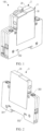
- FIG. 1 shows a schematic structural diagram of a lightning protection device according to an embodiment of the disclosure.
- the lightning protection device 100 described herein generally includes a surge protector 3 and a backup protector 2.
- the surge protector 3 and the backup protector 2 are in a state assembled with each other.
- the combination of surge protector 3 and backup protector 2 may form a 1P lightning protection device connected to a pole of a line.
- the surge protector 3 and the backup protector 2 can be conveniently assembled together, or can be conveniently separated from each other, which will be described in detail hereinafter.
- the surge protector 3 includes a first housing 30. Other components of the surge protector 3 may be disposed in or connected to the first housing 30.
- the backup protector 2 includes a second housing 20. Other components of the backup protector 2 may be disposed in the second housing 20 or on the second housing 20.
- an electrical connector may be provided in at least one of the surge protector 3 and the backup protector 2.
- the assembling manner of the surge protector 3 and the backup protector 2 will be described by using an example in which the electrical connector is disposed in the surge protector 3. It should be understood that the assembling of the surge protector 3 and the backup protector 2 may also be achieved by disposing the electrical connector in the backup protector 2 separately or disposing the electrical connecter in both the surge protector 3 and the backup protector 2, which will be described in further detail below.
- FIG. 2 shows a schematic structural diagram of a surge protector 3 according to an embodiment of the disclosure
- FIG. 3 shows a schematic diagram of an internal structure of the surge protector 3 shown in FIG. 2
- FIG. 4 shows a schematic structural diagram of an electrical connector 10 according to an embodiment of the disclosure
- FIG. 5 shows a schematic structural diagram of a backup protector 2 according to an embodiment of the disclosure
- FIG. 6 shows an assembling schematic diagram of a backup protector 2 and a connecting pin 4 according to an embodiment of the disclosure.
- a side of the first housing 30 facing the backup protector 2 is provided with a first connecting hole 301 located on a live wire side of the surge protector 3.
- a side of the second housing 20 facing the surge protector 3 is provided with a second connecting hole 201 corresponding to the first connecting hole 301, and the second connecting hole 201 is located on the live wire side of the backup protector 2.
- the connecting pin 4 is disposed in the second connecting hole 201.
- An end of the connecting pin 4 is disposed in the second housing 20 for electrical connection with the live wire side of the backup protector 2.
- the other end of the connecting pin 4 extends out of the second housing 20 for electrical connection with the live wire side of the surge protector 3.
- an end of the connecting pin 4 for electrical connecting with the backup protector 2 may also be referred to as a first end of the connecting pin 4
- an end of the connecting pin 4 for electrical connecting with the surge protector 3 may also be referred to as a second end of the connecting pin 4.
- the first end of the connecting pin 4 may be directly or indirectly fixedly connected to the live wire side conductive component of the backup protector 2 via an intermediate connection.
- the connecting pin 4 may be integrally formed directly on the backup protector 2 and the second end of the connecting pin 4 extends out of the second housing 20.
- a second end of the connecting pin 4 may be plugged into the first connecting hole 301 on the surge protector 3 and electrically connected to the live wire side of the surge protector 3.
- the surge protector 3 includes a cover that covers the first connecting hole 301 and is removable from the first connecting hole 301.
- the cover When the surge protector 3 needs to be assembled with the backup protector 2, the cover may be torn away from the first connecting hole 301, and the second end of the connecting pin 4 may be inserted into the first connecting hole 301. When the surge protector 3 is used separately, the cover may cover the first connecting hole 301.
- a first electrical connector 101 may be provided in the surge protector 3, as shown in FIG. 3 .
- the first electrical connector 101 is disposed on the live wire side of the surge protector 3 and is electrically connected to the first live wire side conductive component 31 of the surge protector 3. With the second end of the connecting pin 4 plugged into the first connecting hole 301 on the surge protector 3, the second end of the connecting pin 4 may be electrically connected to the first electrical connector 101.
- the first electrical connector 101 may adopt the structure of the electrical connector 10 shown in FIG. 4 .
- the electrical connector 10 includes a first connecting component 11, a second connecting component 12, and a third connecting component 13.
- the first connecting component 11 is configured to be connected to the first live wire side conductive component 31 of the surge protector 3.
- the second connecting component 12 is configured to be connected to the second end of the connecting pin 4.
- the third connecting component 13 is configured to be connected to the electrical connecting component 34 disposed on the live wire side of the surge protector 3.
- the first connecting component 11 includes a base part 111 and first connecting parts 112 disposed on two opposite sides of the base part 111.
- the first live wire side conductive component 31 may be inserted between and in contact with the first connecting parts 112 disposed on both sides of the base part 111 to achieve an electrical connection between the first connecting component 11 and the first live wire side conductive component 31.
- the second connecting component 12 includes a bent part 121 and a second connecting part 122. An end of the bent part 121 is connected to the first side of the base part 111. The other end of the bent part 121 is connected to the second connecting part 122. A gap 123 is formed between the second connecting part 122 and a surface of the base part 111 facing away from the first connecting parts 112.
- the gap 123 is located at a position corresponding to the first connecting hole 301, and when the second end of the connecting pin 4 is plugged into the first connecting hole 301 on the surge protector 3, the second end of the connecting pin 4 may be inserted into the gap 123 and is in contact with the base part 111 and the second connecting part 122, thereby realizing the electrical connection between the connecting pin 4 and the first electrical connector 101.
- the distance of the gap 123 is controllable and may be selected appropriately as needed.
- the third connecting component 13 is connected to an end of the second connecting part 122 away from the bent part 121 and extends substantially along a direction from the second connecting part 122 to the base part 111.
- the third connecting component 13 may be connected to the electrical connecting component 34 by welding or any available connection way.
- the electrical connecting component 34 may be wired via a wiring hole 303 of the first housing 30 corresponding to the electrical connecting component 34.
- the electrical connecting component 34 does not need to be wired through the wiring hole 303, and only the first electrical connector 101 needs to be connected by using the connecting pin 4.
- the bent part 121 may be generally U-shaped. It should be understood that the bent part 121 may have other shapes as long as the base part 111 and the second connecting part 122 can be connected and the gap 123 can be formed between the second connecting part 122 and the base part 111.
- two first connecting parts 112 are disposed on the first side of the base part 111, and the bent part 121 is connected to a position of the first side of the base part 111 between the two first connecting parts 112.
- more than two first connecting parts 112 may be disposed on the first side of the base part 111, and the bent part 121 is connected to a position between the adjacent first connecting parts 112 on the first side of the base part 111.
- two first connecting parts 112 are disposed on a second side of the base part 111 opposite to the first side, and the two first connecting parts 112 on the second side of the base part 111 correspond to the two first connecting parts 112 on the first side of the base part 111.
- more than two first connecting parts 112 may be correspondingly disposed on the second side of the base part 111, and more than two first connecting parts 112 on the second side of the base part 111 are in one-to-one correspondence with more than two first connecting parts 112 on the first side of the base part 111.
- a protrusion 1221 is provided on a surface of the second connecting part 122 facing the base part 111.
- the second end of the connecting pin 4 may be inserted into the gap 123 and in contact with the base part 111 and the protrusion 1221.
- the second end of the connecting pin 4 can be brought into close contact with the protruding portion 1221, thereby improving the connection reliability between the second end of the connecting pin 4 and the first electrical connector 101.
- the third connecting component 13 of the first electrical connector 101 is substantially perpendicular to the second connecting part 122. It should be understood that, depending on the arrangement orientation of the electrical connecting component 34, it is also possible that the third connecting component 13 is disposed in other direction relative to the second connecting part 122.
- the ground side of the surge protector 3 is provided with a third electrical connector 102, a ground side conductive component 32 and a ground component 33.
- the third electrical connector 102 may adopt the structure of the electrical connector 10 shown in FIG. 4 .
- the first connecting component 11 of the third electrical connector 102 is provided for plugging of the ground side conductive component 32.
- the ground side conductive component 32 may be inserted between the first connecting parts 112 of the third electrical connector 102 disposed on both sides of the base part 111 and in contact with the first connecting parts 112 to achieve an electrical connection between the first connecting component 11 of the third electrical connector 102 and the ground side conductive component 32.
- the third connecting component 13 of the third electrical connector 102 is connected to the ground component 33.
- the third connecting component 13 may be connected to the ground component 33 by welding or any feasible connection way.
- the third connecting component 13 of the third electrical connector 102 is substantially perpendicular to the second connecting part 122. It should be understood that, depending on the arrangement orientation of the ground component 33, it is also possible that the third connecting component 13 of the third electrical connector 102 is disposed in other direction relative to the second connecting part 122.
- the assembling of the surge protector 3 and the backup protector 2 may also be achieved by disposing the electrical connector in the backup protector 2 separately or disposing the electrical connecter in both the surge protector 3 and the backup protector 2.
- further description will be given for these two cases.
- the electrical connector 10 is provided separately in the backup protector 2 is first described, that is, the electrical connector 10 is only provided on the live wire side of the backup protector 2, and the electrical connector 10 is not provided on the live wire side of the surge protector 3.
- the second end of the connecting pin 4 may be directly or indirectly fixedly connected to the live wire side of the surge protector 3 via an intermediate connection.
- the connecting pin 4 may be directly integrally formed on the surge protector 3. Similar to the case described above in connection with FIGS. 2-6 , the first end of the connecting pin 4 may be plugged into the second connecting hole 201 on the backup protector 2 and electrically connected to the live wire side of the backup protector 2.
- a second electrical connector (not shown) may be provided in the backup protector 2.
- the second electrical connector is disposed on the live wire side of the backup protector 2 and is electrically connected to the second live wire side conductive component (not shown) of the backup protector 2. With the first end of the connecting pin 4 plugged into the second connecting hole 201 on the backup protector 2, the first end of the connecting pin 4 may be electrically connected to the second electrical connector.
- the second electrical connector may also adopt the structure of the electrical connector 10 shown in FIG. 4 .
- the second live wire side conductive component of the backup protector 2 may be inserted between and in contact with the first connecting parts 112 of the second electrical connector disposed on both sides of the base part 111 to achieve an electrical connection between the first connecting component 11 and the second live wire side conductive component of the second electrical connector.
- the gap 123 of the second electrical connector is disposed at a position corresponding to the second connecting hole 201. With the first end of the connecting pin 4 plugged into the second connecting hole 201 on the backup protector 2, the first end of the connecting pin 4 may be inserted into the gap 123 of the second electrical connector and in contact with the base part 111 and the second connecting part 122 of the second electrical connector, thereby achieving an electrical connection between the connecting pin 4 and the second electrical connector. In this way, the surge protector 3 and the backup protector 2 can be conveniently assembled together.
- the backup protector 2 includes a cover that covers the second connecting hole 201 and is removable from the second connecting hole 201.
- the cover may be torn away from the second connecting hole 201, and the first end of the connecting pin 4 may be inserted into the second connecting hole 201.
- the cover may cover the second connecting hole 201.
- the surge protector 3 may be provided with the first electrical connector 101 as described above
- the backup protector 2 may be provided with the second electrical connector as described above.
- the first end of the connecting pin 4 may be inserted into the second connecting hole 201 on the backup protector 2
- the second end of the connecting pin 4 may be inserted into the first connecting hole 301 on the surge protector 3.
- the first end of the connecting pin 4 may extend into the gap 123 on the second electrical connector and be in contact with the base part 111 and the second connecting part 122 of the second electrical connector.
- the second end of the connecting pin 4 may extend into the gap 123 on the first electrical connector 101 and be in contact with the base part 111 and the second connecting part 122 of the first electrical connector 101. In this way, the surge protector 3 and the backup protector 2 may also be conveniently assembled together.
- the first connecting hole 301 and the second connecting hole 201 may both be provided with a covering component.
- the cover can be torn off from the first connecting hole 301 and the second connecting hole 201, and two ends of the connecting pin 4 are respectively inserted into the first connecting hole 301 and the second connecting hole 201.
- slots are respectively disposed at corresponding positions on the first housing 30 and the second housing 20.
- the surge protector 3 and the backup protector 2 may be assembled together by clamping a hook in the slot. In this way, the surge protector 3 and the backup protector 2 can be conveniently and reliably fixed together. It should be understood that other fixing manners are feasible, such as by screws, which is not limited in the embodiments of the disclosure.
- the surge protector 3 and the backup protector 2 can be conveniently connected, so that the user can select the required surge protector 3 and the backup protector 2 for flexible assembling according to requirements.
- FIG. 7 shows a schematic diagram of an internal structure of a surge protector 3 according to another embodiment of the disclosure.
- the structure of the surge protector 3 shown in FIG. 7 is similar to that of the surge protector 3 shown in FIG. 3 , except that the electrical connecting component 34 is not provided in the surge protector 3 shown in FIG. 7 , and the arrangement of the first electrical connector 101 is different from the surge protector 3 shown in FIG. 3 . Only differences between them will be described in detail below, and the same parts will not be repeated.
- the first electrical connector 101 is disposed on the live wire side of the surge protector 3, and the first connecting component 11 thereof is electrically connected to the first live wire side conductive component 31 of the surge protector 3.
- the second end of the connecting pin 4 may be inserted into the gap 123 between the first connecting component 11 and the second connecting component 12 of the first electrical connector 101.
- the third connecting component 13 of the first electrical connector 101 is not used in this embodiment, i.e., is not electrically connected to other components.
- the surge protector 3 and the backup protector 2 may also be conveniently assembled together using a connecting pin 4.
- the lightning protection device 100 described above in connection with FIGS. 1-6 is a 1P lightning protection device for connecting to one pole of the line.
- multiple poles of the line need to be connected to the lightning protection device.
- the lightning protection device 100 may include multiple sets of surge protectors 3 and backup protectors 2, where each set of surge protectors 3 and backup protectors 2 may be assembled together in the manner described in connection with FIGS. 1-6 and connected to the respective one pole of the line.
- the lightning protection device 100 When the lightning protection device 100 includes two sets of surge protectors 3 and backup protectors 2, the lightning protection device 100 may be referred to as a 2P lightning protection device, and when the lightning protection device 100 includes three sets of surge protectors 3 and backup protectors 2, the lightning protection device 100 may be referred to as a 3P lightning protection device, and the like.
- the lightning protection device 100 includes two sets of surge protectors 3 and backup protectors 2 is used as an example to describe an assembling manner of the plurality of sets of surge protectors 3 and backup protectors 2, as shown in FIGS. 8 to 11 . It should be understood that the plurality of sets of surge protectors 3 and backup protectors 2 may be assembled in a similar manner, which will not be described in detail herein again.
- the first backup protector 210 and the first surge protector 310 may constitute a first phase protection unit 110 by using the assembling manner described above for connecting one pole of the line.
- the second backup protector 220 and the second surge protector 320 may constitute a second phase protection unit 120 by using the assembling manner described above for connecting the other pole of the line.
- the first backup protector 210 and the second backup protector 220 may adopt the structure of the backup protector 2 described above.
- One of the first surge protector 310 and the second surge protector 320 may adopt the structure of the surge protector 3 described above.
- the other of the first surge protector 310 and the second surge protector 320 may employ a structure similar to the surge protector 3 described above, except that the ground component 33 need not be provided.
- the ground side of the first surge protector 310 may be electrically connected to the ground side of the second surge protector 320 via the current converging component 5.
- the lightning protection device 10 includes the plurality of sets of surge protectors 3 and backup protectors 2
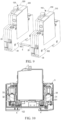
- a third connecting hole 302 is provided on a side of the first housing 30 of the first surge protector 310 facing the first backup protector 210, and the third connecting hole 302 is located at a position corresponding to the gap 123 of the third electrical connector 102 of the first surge protector 310.
- a side of the first housing 30 of the second surge protector 320 facing away from the second backup protector 220 is provided with a third connecting hole 302 located at a position corresponding to the gap 123 of the third electrical connector 102 of the second surge protector 320.
- fourth connecting holes 202 are disposed on two opposite sides of the second housing 20 of the first backup protector 210, and the fourth connecting hole 202 is disposed at a position corresponding to the third connecting hole 302.
- an end of the current converging component 5 may be inserted into the gap 123 of the third electrical connector 102 in the second surge protector 320 via the third connecting hole 302 on the second surge protector 320 and in contact with the base part 111 and the second connecting part 122.
- the other end of the current converging component 5 may pass through the fourth connecting hole 202 on the first backup protector 210 and be inserted into the gap 123 of the third electrical connector 102 in the first surge protector 310 via the third connecting hole 302 on the first surge protector 310 and in contact with the base part 111 and the second connecting part 122.
- a side of the first housing 30 of the first surge protector 310 facing away from the first backup protector 210 may also be provided with a third connecting hole 302, so as to further connect the one or more phase protection units on the right side of the first surge protector 310 by using the current converging component 5.
- a side of the first housing 30 of the second surge protector 320 facing the second backup protector 220 may also be provided with a third connecting hole 302, and the opposite sides of the second housing 20 of the second backup protector 220 are also provided with fourth connecting holes 202, so as to further connect the one or more phase protection units on the left side of the second backup protector 220 by using the current converging component 5.
- the current converging component 5 is generally a sheet-like structure.
- the size of both ends of the current converging component 5 may be slightly smaller than the size of the intermediate portion for easier insertion into the respective connecting hole.
Landscapes
- Engineering & Computer Science (AREA)
- Power Engineering (AREA)
- Emergency Protection Circuit Devices (AREA)
Abstract
Description
- Embodiments of the disclosure generally relate to the technical field of electrical equipment, and more particularly, to a lightning protection device, a surge protector, a backup protector, and an electrical connector.
- A surge protector (SPD), also referred to as a lightning protector, is an electronic apparatus that provides safety protection for various electronic devices, instruments and meters, and communication lines. In a low-voltage power distribution system, when a spike current or voltage (for example, an overvoltage caused by lightning) is suddenly generated in an electrical loop or a communication line due to an external disturbance, the surge protector can be switched on to shunt in a very short time, thereby avoiding damage to other devices in the circuit by surge.
- SSD is a backup protector in series at the front end of the SPD, which is also referred to as an external disconnector. The SSD, as a backup protection device for a new-generation surge protector, has high disconnection capacity upon occurrence of a short-circuit current, and has high surge-tolerance capability, and a short-circuit action current of the SSD is far lower than that of a traditional backup protection device under the condition of considering the disconnection capacity and the surge-tolerance capability. The low short-circuit current can be effectively disconnected, providing finer short-circuit protection for the surge protector.
- In order to realize the connection between the SSD and the SPD, a conventional solution is to form the SSD and the SPD into independent products, and the connection between the SSD and the SPD is realized through wires. However, the additional wires increase product costs and are inconvenient to use. Another conventional solution is to form the SSD and the SPD into an integral product. This solution limits the use flexibility of the product, and when there is a problem with one of the SSD and the SPD, the SSD and the SPD can only be replaced as a whole, and the part that has the problem cannot be replaced separately.
- An object of the disclosure is to provide a lightning protection device, a surge protector, a backup protector and an electrical connector, to at least partially solve the above problems.
- In a first aspect of the disclosure, there is provided a lightning protection device including a surge protector and a backup protector capable of being connected via a connecting pin. The surge protector includes: a first housing, a side of the first housing facing the backup protector being provided with a first connecting hole; and a first live wire side conductive component disposed in the first housing. The backup protector includes: a second housing, a side of the second housing facing the surge protector being provided with a second connecting hole corresponding to the first connecting hole; and a second live wire side conductive component disposed in the second housing. At least one of the backup protector and the surge protector further includes an electrical connector disposed in the respective housing and electrically connected to the respective live wire side conductive component, and the connecting pin passes through the first connecting hole and the second connecting hole and is plugged into the electrical connector.
- In some embodiments, the electrical connector includes a first connecting component, a second connecting component and a third connecting component, the first connecting component includes a base part and first connecting parts disposed on two opposite sides of the base part, the second connecting component includes a bent part and a second connecting part, an end of the bent part is connected to a first side of the base part, the other end of the bent part is connected to the second connecting part, a gap is formed between the second connecting part and a surface of the base part facing away from the first connecting parts, the gap is located at a position corresponding to the respective connecting hole, the connecting pin passes through the first connecting hole and the second connecting hole and is inserted into the gap to be in contact with the base part and the second connecting part, the first connecting component is provided for plugging of the respective live wire side conductive component, and the third connecting component is connected to an end of the second connecting part away from the bent part and extends in a direction from the second connecting part to the base part.
- In some embodiments, the surge protector includes a first electrical connector, the backup protector includes a second electrical connector, the first electrical connector and the second electrical connector are respectively configured as the electrical connector, an end of the connecting pin is inserted into the gap of the first electrical connector, and the other end of the connecting pin is inserted into the gap of the second electrical connector.
- In some embodiments, the surge protector includes a first electrical connector configured as the electrical connector, an end of the connecting pin is inserted into the gap of the first electrical connector, and the other end of the connecting pin is fixedly connected to the backup protector and is electrically connected to the second live wire side conductive component.
- In some embodiments, the surge protector further includes an electrical connecting component disposed on a live wire side, and the third connecting component of the first electrical connector is connected to the electrical connecting component.
- In some embodiments, the backup protector includes a second electrical connector configured as the electrical connector, an end of the connecting pin is inserted into the gap of the second electrical connector, and the other end of the connecting pin is fixedly connected to the surge protector and electrically connected to the first live wire side conductive component.
- In some embodiments, the surge protector further includes a third electrical connector, a ground side conductive component and a ground component, the third electrical connector is configured as the electrical connector, the first connecting component of the third electrical connector is provided for plugging of the ground side conductive component, and the third connecting component of the third electrical connector is connected to the ground component.
- In some embodiments, a third connecting hole is provided on the first housing at a position corresponding to the gap of the third electrical connector.
- In some embodiments, the backup protector is a first backup protector, the surge protector is a first surge protector, the first backup protector and the first surge protector constitute a first phase protection unit, and the lightning protection device further includes a second phase protection unit and a current converging component, the second phase protection unit includes a second backup protector and a second surge protector connected via the connecting pin, the second surge protector includes the first housing, the ground side conductive component and the third electrical connector, the current converging component passes through the gap of the third electrical connector of the first surge protector, the third connecting hole on the first housing of the first surge protector, the third connecting hole on the first housing of the second surge protector, and the gap of the third electrical connector of the second surge protector, and contacts the base part of the third electrical connector and the second connecting part.
- In some embodiments, the second housing is provided with a fourth connecting hole corresponding to the third connecting hole, and the current converging component further passes through the fourth connecting hole.
- In some embodiments, the first side of the base part is provided with at least two first connecting parts, and the bent part is connected to a position of the first side of the base part between adjacent first connecting parts.
- In some embodiments, a surface of the second connecting part facing the base part is provided with a protrusion.
- In a second aspect of the disclosure, there is provided a surge protector including: a first housing provided with a first connecting hole; a first electrical connector disposed in the first housing and including a first connecting component, a second connecting component and a third connecting component, wherein the first connecting component includes a base part and first connecting parts disposed on two opposite sides of the base part, the second connecting component includes a bent part and a second connecting part, an end of the bent part is connected to a first side of the base part, the other end of the bent part is connected to the second connecting part, a gap is formed between the second connecting part and a surface of the base part facing away from the first connecting parts, the gap is located at a position corresponding to the first connecting hole, and the third connecting component is connected to an end of the second connecting part away from the bent part and extends in a direction from the second connecting part to the base part; and a first live wire side conductive component disposed in the first housing and plugged into the first connecting component.
- In some embodiments, the surge protector further includes a cover covering the first connecting hole and removable from the first connecting hole.
- In some embodiments, the surge protector further includes a third electrical connector, a ground side conductive component and a ground component, wherein the third electrical connector includes a first connecting component, a second connecting component and a third connecting component, the first connecting component includes a base part and first connecting parts disposed on two opposite sides of the base part, the second connecting component includes a bent part and a second connecting part, an end of the bent part is connected to a first side of the base part, the other end of the bent part is connected to the second connecting part, a gap is formed between the second connecting part and a surface of the base part facing away from the first connecting parts, the third connecting component is connected to an end of the second connecting part away from the bent part and extends in a direction from the second connecting part to the base part, the first connecting component of the third electrical connector is provided for plugging of the ground side conductive component, and the third connecting component of the third electrical connector is connected to the ground component.
- In some embodiments, the surge protector further includes an electrical connecting component disposed on a live wire side in the first housing and connected to the third connecting component of the first electrical connector.
- In a third aspect of the disclosure, there is provided a backup protector including: a second housing provided with a second connecting hole; a second electrical connector disposed in the second housing and including a first connecting component, a second connecting component and a third connecting component, the first connecting component includes a base part and first connecting parts disposed on two opposite sides of the base part, the second connecting component includes a bent part and a second connecting part, an end of the bent part is connected to a first side of the base part, the other end of the bent part is connected to the second connecting part, a gap is formed between the second connecting part and a surface of the base part facing away from the first connecting parts, wherein the gap is located at a position corresponding to the second connecting hole, and the third connecting component is connected to an end of the second connecting part away from the bent part and extends in a direction from the second connecting part to the base part; and a second live wire side conductive component disposed in the second housing and plugged into the first connecting component.
- In some embodiments, the backup protector further includes a cover covering the second connecting hole and removable from the second connecting hole.
- In a fourth aspect of the disclosure, there is provided an electrical connector suitable for a surge protector or a backup protector, the electrical connector including: a first connecting component including a base part and first connecting parts disposed on two opposite sides of the base part; a second connecting component including a bent part and a second connecting part, an end of the bent part being connected to a first side of the base part, the other end of the bent part being connected to the second connecting part, a gap being formed between the second connecting part and a surface of the base part facing away from the first connecting parts; and a third connecting component connected to an end of the second connecting part away from the bent part and extending in a direction from the second connecting part to the base part.
- In some embodiments, the first side of the base part is provided with at least two first connecting parts, and the bent part is connected to a position of the first side of the base part between adjacent first connecting parts.
- In some embodiments, a surface of the second connecting part facing the base part is provided with a protrusion.
- According to embodiments of the disclosure, the surge protector and the backup protector can be conveniently connected together by the connecting pin. On the one hand, the tedious operation upon connection through the wires can be avoided, and the cost can be saved. On the other hand, since the surge protector and the backup protector are provided separately, when there is problem with one of the surge protector and the backup protector, it can only replace the part that has the problem without need of replacing the whole product.
- It should be understood that the content described in the summary is not intended to limit critical or important features of the embodiments of the disclosure, nor is it intended to limit the scope of the disclosure. Other features of the disclosure will become readily understood from the following description.
- The above and other features, advantages, and aspects of various embodiments of the disclosure will become more apparent from the following detailed description taken in conjunction with the accompanying drawings. In the drawings, the same or similar reference numbers refer to the same or similar elements, wherein:
-
FIG. 1 shows a schematic structural diagram of a lightning protection device according to an embodiment of the disclosure; -
FIG. 2 shows a schematic structural diagram of a surge protector according to an embodiment of the disclosure; -
FIG. 3 shows a schematic diagram of an internal structure of the surge protector shown inFIG. 2 ; -
FIG. 4 shows a schematic structural diagram of an electrical connector according to an embodiment of the disclosure; -
FIG. 5 shows a schematic structural diagram of a backup protector according to an embodiment of the disclosure; -
FIG. 6 shows a schematic assembling diagram of a backup protector and a connecting pin according to an embodiment of the disclosure; -
FIG. 7 shows a schematic diagram of an internal structure of a surge protector according to another embodiment of the disclosure; -
FIG. 8 shows a schematic structural diagram of a lightning protection device according to another embodiment of the disclosure; -
FIG. 9 shows an schematic explosive view of the lightning protection device shown inFIG. 8 ; -
FIG. 10 shows a schematic diagram of an internal structure of a first surge protector in the lightning protection device shown inFIG. 9 ; and -
FIG. 11 shows a schematic structural diagram of a current converging component according to an embodiment of the disclosure. - 10 electrical connector; 101 first electrical connector; 102 third electrical connector; 11 first connecting component; 111 base part; 112 first connecting part; 12 second connecting component; 121 bent part; 122 second connecting part; 1221 protrusion; 123 gap; 13 third connecting component; 3 surge protector; 310 first surge protector; 320 second surge protector; 30 first housing; 301 first connecting hole; 302 third connecting hole; 303 wiring hole; 31 first live wire side conductive component; 32 ground side conductive component; 2 backup protector; 210 first backup protector; 220 second backup protector; 20 second housing; 201 second connecting hole; 202 fourth connecting hole; 33 ground component; 34 electrical connecting component; 4 connecting pin; 5 current converging component; 100 lightning protection device; 110 first phase protection unit; 120 second phase protection unit.
- Preferred embodiments of the disclosure will be described in more detail below with reference to the accompanying drawings. While the preferred embodiments of the disclosure are shown in the drawings, it should be understood that the disclosure may be implemented in various forms and should not be limited by the embodiments set forth herein. Rather, these embodiments are provided to make this disclosure more thorough and complete, and to fully convey the scope of the disclosure to those skilled in the art.
- As used herein, the term "comprising" and variations thereof represent openness, i.e., "including but not limited to". Unless specifically stated, the term "or" means "and/or". The term "based on" means "based at least in part on". The terms "an example embodiment" and "an embodiment" mean "at least one example embodiment". The term "another embodiment" means "at least one further embodiment". The terms "first," "second," and the like may refer to different or identical objects.
- As described above, connecting the SSD with the SPD via the wire increases the product cost and is inconvenient to use, and the formation of the SSD and the SPD into an integral product limits the use flexibility of the product, and when there is a problem with one of the SSD and the SPD, the SSD and the SPD can only be replaced as a whole, and the part that has the problem cannot be replaced separately. According to the embodiments of the disclosure, by providing an electrical connector in at least one of the surge protector and the backup protector, the connection of the surge protector and the backup protector can be conveniently realized by using a connecting pin in a plugging manner. On the one hand, the tedious operation upon connection through the wires can be avoided, and the cost can be saved. On the other hand, since the surge protector and the backup protector are provided separately, when there is problem with one of the surge protector and the backup protector, it can only replace the part that has the problem without need of replacing the whole product. The principle of the disclosure will be described below with reference to
FIGS. 1 11 . -
FIG. 1 shows a schematic structural diagram of a lightning protection device according to an embodiment of the disclosure. As shown inFIG. 1 , thelightning protection device 100 described herein generally includes asurge protector 3 and abackup protector 2. Thesurge protector 3 and thebackup protector 2 are in a state assembled with each other. The combination ofsurge protector 3 andbackup protector 2 may form a 1P lightning protection device connected to a pole of a line. In the embodiments of the disclosure, thesurge protector 3 and thebackup protector 2 can be conveniently assembled together, or can be conveniently separated from each other, which will be described in detail hereinafter. - As shown in
FIG. 1 , thesurge protector 3 includes afirst housing 30. Other components of thesurge protector 3 may be disposed in or connected to thefirst housing 30. Thebackup protector 2 includes asecond housing 20. Other components of thebackup protector 2 may be disposed in thesecond housing 20 or on thesecond housing 20. - In order to achieve the assembling of the
surge protector 3 and thebackup protector 2, an electrical connector may be provided in at least one of thesurge protector 3 and thebackup protector 2. Hereafter, the assembling manner of thesurge protector 3 and thebackup protector 2 will be described by using an example in which the electrical connector is disposed in thesurge protector 3. It should be understood that the assembling of thesurge protector 3 and thebackup protector 2 may also be achieved by disposing the electrical connector in thebackup protector 2 separately or disposing the electrical connecter in both thesurge protector 3 and thebackup protector 2, which will be described in further detail below. -
FIG. 2 shows a schematic structural diagram of asurge protector 3 according to an embodiment of the disclosure,FIG. 3 shows a schematic diagram of an internal structure of thesurge protector 3 shown inFIG. 2 ,FIG. 4 shows a schematic structural diagram of anelectrical connector 10 according to an embodiment of the disclosure,FIG. 5 shows a schematic structural diagram of abackup protector 2 according to an embodiment of the disclosure, andFIG. 6 shows an assembling schematic diagram of abackup protector 2 and a connectingpin 4 according to an embodiment of the disclosure. - In an embodiment, as shown in
FIG. 2 , a side of thefirst housing 30 facing thebackup protector 2 is provided with a first connectinghole 301 located on a live wire side of thesurge protector 3. Correspondingly, as shown inFIG. 5 , a side of thesecond housing 20 facing thesurge protector 3 is provided with a second connectinghole 201 corresponding to the first connectinghole 301, and the second connectinghole 201 is located on the live wire side of thebackup protector 2. With thesurge protector 3 and thebackup protector 2 assembled together, the first connectinghole 301 and the second connectinghole 201 are substantially aligned. The electrical connection between the live wire side of thesurge protector 3 and the live wire side of thebackup protector 2 may be achieved by a connectingpin 4 passing through the first connectinghole 301 and the second connectinghole 201. - In an embodiment, as shown in
FIG. 6 , the connectingpin 4 is disposed in the second connectinghole 201. An end of the connectingpin 4 is disposed in thesecond housing 20 for electrical connection with the live wire side of thebackup protector 2. The other end of the connectingpin 4 extends out of thesecond housing 20 for electrical connection with the live wire side of thesurge protector 3. Herein, for ease of description, an end of the connectingpin 4 for electrical connecting with thebackup protector 2 may also be referred to as a first end of the connectingpin 4, and an end of the connectingpin 4 for electrical connecting with thesurge protector 3 may also be referred to as a second end of the connectingpin 4. - In an embodiment, the first end of the connecting
pin 4 may be directly or indirectly fixedly connected to the live wire side conductive component of thebackup protector 2 via an intermediate connection. In other words, the connectingpin 4 may be integrally formed directly on thebackup protector 2 and the second end of the connectingpin 4 extends out of thesecond housing 20. A second end of the connectingpin 4 may be plugged into the first connectinghole 301 on thesurge protector 3 and electrically connected to the live wire side of thesurge protector 3. In an embodiment, thesurge protector 3 includes a cover that covers the first connectinghole 301 and is removable from the first connectinghole 301. When thesurge protector 3 needs to be assembled with thebackup protector 2, the cover may be torn away from the first connectinghole 301, and the second end of the connectingpin 4 may be inserted into the first connectinghole 301. When thesurge protector 3 is used separately, the cover may cover the first connectinghole 301. - To connect the second end of the connecting
pin 4 to the live wire side of thesurge protector 3, a firstelectrical connector 101 may be provided in thesurge protector 3, as shown inFIG. 3 . The firstelectrical connector 101 is disposed on the live wire side of thesurge protector 3 and is electrically connected to the first live wire sideconductive component 31 of thesurge protector 3. With the second end of the connectingpin 4 plugged into the first connectinghole 301 on thesurge protector 3, the second end of the connectingpin 4 may be electrically connected to the firstelectrical connector 101. The firstelectrical connector 101 may adopt the structure of theelectrical connector 10 shown inFIG. 4 . - In an embodiment, as shown in
FIG. 4 , theelectrical connector 10 includes a first connectingcomponent 11, a second connectingcomponent 12, and a third connectingcomponent 13. The first connectingcomponent 11 is configured to be connected to the first live wire sideconductive component 31 of thesurge protector 3. The second connectingcomponent 12 is configured to be connected to the second end of the connectingpin 4. The third connectingcomponent 13 is configured to be connected to the electrical connectingcomponent 34 disposed on the live wire side of thesurge protector 3. The first connectingcomponent 11 includes abase part 111 and first connectingparts 112 disposed on two opposite sides of thebase part 111. The first live wire sideconductive component 31 may be inserted between and in contact with the first connectingparts 112 disposed on both sides of thebase part 111 to achieve an electrical connection between the first connectingcomponent 11 and the first live wire sideconductive component 31. The second connectingcomponent 12 includes abent part 121 and a second connectingpart 122. An end of thebent part 121 is connected to the first side of thebase part 111. The other end of thebent part 121 is connected to the second connectingpart 122. Agap 123 is formed between the second connectingpart 122 and a surface of thebase part 111 facing away from the first connectingparts 112. With reference toFIGS. 2-6 , thegap 123 is located at a position corresponding to the first connectinghole 301, and when the second end of the connectingpin 4 is plugged into the first connectinghole 301 on thesurge protector 3, the second end of the connectingpin 4 may be inserted into thegap 123 and is in contact with thebase part 111 and the second connectingpart 122, thereby realizing the electrical connection between the connectingpin 4 and the firstelectrical connector 101. The distance of thegap 123 is controllable and may be selected appropriately as needed. The third connectingcomponent 13 is connected to an end of the second connectingpart 122 away from thebent part 121 and extends substantially along a direction from the second connectingpart 122 to thebase part 111. The third connectingcomponent 13 may be connected to the electrical connectingcomponent 34 by welding or any available connection way. - When the
surge protector 3 is used separately, the electrical connectingcomponent 34 may be wired via awiring hole 303 of thefirst housing 30 corresponding to the electrical connectingcomponent 34. When thesurge protector 3 and thebackup protector 2 need to be assembled, the electrical connectingcomponent 34 does not need to be wired through thewiring hole 303, and only the firstelectrical connector 101 needs to be connected by using the connectingpin 4. - In an embodiment, as shown in
FIGS. 3 and 4 , thebent part 121 may be generally U-shaped. It should be understood that thebent part 121 may have other shapes as long as thebase part 111 and the second connectingpart 122 can be connected and thegap 123 can be formed between the second connectingpart 122 and thebase part 111. - In an embodiment, as shown in
FIG. 4 , two first connectingparts 112 are disposed on the first side of thebase part 111, and thebent part 121 is connected to a position of the first side of thebase part 111 between the two first connectingparts 112. In some embodiments, more than two first connectingparts 112 may be disposed on the first side of thebase part 111, and thebent part 121 is connected to a position between the adjacent first connectingparts 112 on the first side of thebase part 111. When the first live wire sideconductive component 31 is inserted into the first connectingcomponent 11, it may contact each of the first connectingparts 112 to improve connection reliability. - In an embodiment, as shown in
FIG. 4 , two first connectingparts 112 are disposed on a second side of thebase part 111 opposite to the first side, and the two first connectingparts 112 on the second side of thebase part 111 correspond to the two first connectingparts 112 on the first side of thebase part 111. In some embodiments, in a case where more than two first connectingparts 112 are disposed on the first side of thebase part 111, more than two first connectingparts 112 may be correspondingly disposed on the second side of thebase part 111, and more than two first connectingparts 112 on the second side of thebase part 111 are in one-to-one correspondence with more than two first connectingparts 112 on the first side of thebase part 111. - In an embodiment, as shown in
FIG. 4 , aprotrusion 1221 is provided on a surface of the second connectingpart 122 facing thebase part 111. With the second end of the connectingpin 4 plugged into the first connectinghole 301 on thesurge protector 3, the second end of the connectingpin 4 may be inserted into thegap 123 and in contact with thebase part 111 and theprotrusion 1221. With this arrangement, the second end of the connectingpin 4 can be brought into close contact with the protrudingportion 1221, thereby improving the connection reliability between the second end of the connectingpin 4 and the firstelectrical connector 101. - In some embodiments, as shown in
FIG. 4 , the third connectingcomponent 13 of the firstelectrical connector 101 is substantially perpendicular to the second connectingpart 122. It should be understood that, depending on the arrangement orientation of the electrical connectingcomponent 34, it is also possible that the third connectingcomponent 13 is disposed in other direction relative to the second connectingpart 122. In some embodiments, as shown inFIG. 3 , the ground side of thesurge protector 3 is provided with a thirdelectrical connector 102, a ground sideconductive component 32 and aground component 33. The thirdelectrical connector 102 may adopt the structure of theelectrical connector 10 shown inFIG. 4 . The first connectingcomponent 11 of the thirdelectrical connector 102 is provided for plugging of the ground sideconductive component 32. The ground sideconductive component 32 may be inserted between the first connectingparts 112 of the thirdelectrical connector 102 disposed on both sides of thebase part 111 and in contact with the first connectingparts 112 to achieve an electrical connection between the first connectingcomponent 11 of the thirdelectrical connector 102 and the ground sideconductive component 32. The third connectingcomponent 13 of the thirdelectrical connector 102 is connected to theground component 33. The third connectingcomponent 13 may be connected to theground component 33 by welding or any feasible connection way. - In some embodiments, as shown in
FIG. 4 , the third connectingcomponent 13 of the thirdelectrical connector 102 is substantially perpendicular to the second connectingpart 122. It should be understood that, depending on the arrangement orientation of theground component 33, it is also possible that the third connectingcomponent 13 of the thirdelectrical connector 102 is disposed in other direction relative to the second connectingpart 122. - As described above, the assembling of the
surge protector 3 and thebackup protector 2 may also be achieved by disposing the electrical connector in thebackup protector 2 separately or disposing the electrical connecter in both thesurge protector 3 and thebackup protector 2. Hereafter, further description will be given for these two cases. - The case where the
electrical connector 10 is provided separately in thebackup protector 2 is first described, that is, theelectrical connector 10 is only provided on the live wire side of thebackup protector 2, and theelectrical connector 10 is not provided on the live wire side of thesurge protector 3. In this case, the second end of the connectingpin 4 may be directly or indirectly fixedly connected to the live wire side of thesurge protector 3 via an intermediate connection. In other words, the connectingpin 4 may be directly integrally formed on thesurge protector 3. Similar to the case described above in connection withFIGS. 2-6 , the first end of the connectingpin 4 may be plugged into the second connectinghole 201 on thebackup protector 2 and electrically connected to the live wire side of thebackup protector 2. To connect the first end of the connectingpin 4 to the live wire side of thebackup protector 2, a second electrical connector (not shown) may be provided in thebackup protector 2. The second electrical connector is disposed on the live wire side of thebackup protector 2 and is electrically connected to the second live wire side conductive component (not shown) of thebackup protector 2. With the first end of the connectingpin 4 plugged into the second connectinghole 201 on thebackup protector 2, the first end of the connectingpin 4 may be electrically connected to the second electrical connector. The second electrical connector may also adopt the structure of theelectrical connector 10 shown inFIG. 4 . - The second live wire side conductive component of the
backup protector 2 may be inserted between and in contact with the first connectingparts 112 of the second electrical connector disposed on both sides of thebase part 111 to achieve an electrical connection between the first connectingcomponent 11 and the second live wire side conductive component of the second electrical connector. Thegap 123 of the second electrical connector is disposed at a position corresponding to the second connectinghole 201. With the first end of the connectingpin 4 plugged into the second connectinghole 201 on thebackup protector 2, the first end of the connectingpin 4 may be inserted into thegap 123 of the second electrical connector and in contact with thebase part 111 and the second connectingpart 122 of the second electrical connector, thereby achieving an electrical connection between the connectingpin 4 and the second electrical connector. In this way, thesurge protector 3 and thebackup protector 2 can be conveniently assembled together. - In an embodiment, the
backup protector 2 includes a cover that covers the second connectinghole 201 and is removable from the second connectinghole 201. When thesurge protector 3 needs to be assembled with thebackup protector 2, the cover may be torn away from the second connectinghole 201, and the first end of the connectingpin 4 may be inserted into the second connectinghole 201. In the case where thebackup protector 2 is used separately, the cover may cover the second connectinghole 201. - The following describes the case in which the
electrical connector 10 is provided in both thesurge protector 3 and thebackup protector 2. In this case, thesurge protector 3 may be provided with the firstelectrical connector 101 as described above, and thebackup protector 2 may be provided with the second electrical connector as described above. When assembling thesurge protector 3 and thebackup protector 2, the first end of the connectingpin 4 may be inserted into the second connectinghole 201 on thebackup protector 2, and the second end of the connectingpin 4 may be inserted into the first connectinghole 301 on thesurge protector 3. The first end of the connectingpin 4 may extend into thegap 123 on the second electrical connector and be in contact with thebase part 111 and the second connectingpart 122 of the second electrical connector. The second end of the connectingpin 4 may extend into thegap 123 on the firstelectrical connector 101 and be in contact with thebase part 111 and the second connectingpart 122 of the firstelectrical connector 101. In this way, thesurge protector 3 and thebackup protector 2 may also be conveniently assembled together. - In an embodiment, the first connecting
hole 301 and the second connectinghole 201 may both be provided with a covering component. When thesurge protector 3 needs to be assembled with thebackup protector 2, the cover can be torn off from the first connectinghole 301 and the second connectinghole 201, and two ends of the connectingpin 4 are respectively inserted into the first connectinghole 301 and the second connectinghole 201. - In some embodiments, slots (not shown) are respectively disposed at corresponding positions on the
first housing 30 and thesecond housing 20. After connecting thesurge protector 3 with thebackup protector 2 by using the connectingpin 4, thesurge protector 3 and thebackup protector 2 may be assembled together by clamping a hook in the slot. In this way, thesurge protector 3 and thebackup protector 2 can be conveniently and reliably fixed together. It should be understood that other fixing manners are feasible, such as by screws, which is not limited in the embodiments of the disclosure. - According to the embodiments of the disclosure, by using the
electrical connector 10 having the first connectingcomponent 11 and the second connectingcomponent 12, thesurge protector 3 and thebackup protector 2 can be conveniently connected, so that the user can select the requiredsurge protector 3 and thebackup protector 2 for flexible assembling according to requirements. -
FIG. 7 shows a schematic diagram of an internal structure of asurge protector 3 according to another embodiment of the disclosure. The structure of thesurge protector 3 shown inFIG. 7 is similar to that of thesurge protector 3 shown inFIG. 3 , except that the electrical connectingcomponent 34 is not provided in thesurge protector 3 shown inFIG. 7 , and the arrangement of the firstelectrical connector 101 is different from thesurge protector 3 shown inFIG. 3 . Only differences between them will be described in detail below, and the same parts will not be repeated. - As shown in
FIG. 7 , the firstelectrical connector 101 is disposed on the live wire side of thesurge protector 3, and the first connectingcomponent 11 thereof is electrically connected to the first live wire sideconductive component 31 of thesurge protector 3. With the second end of the connectingpin 4 plugged into the first connectinghole 301 on thesurge protector 3, the second end of the connectingpin 4 may be inserted into thegap 123 between the first connectingcomponent 11 and the second connectingcomponent 12 of the firstelectrical connector 101. The third connectingcomponent 13 of the firstelectrical connector 101 is not used in this embodiment, i.e., is not electrically connected to other components. With such an embodiment, thesurge protector 3 and thebackup protector 2 may also be conveniently assembled together using a connectingpin 4. - The
lightning protection device 100 described above in connection withFIGS. 1-6 is a 1P lightning protection device for connecting to one pole of the line. In some embodiments, multiple poles of the line need to be connected to the lightning protection device. In this case, thelightning protection device 100 may include multiple sets ofsurge protectors 3 andbackup protectors 2, where each set ofsurge protectors 3 andbackup protectors 2 may be assembled together in the manner described in connection withFIGS. 1-6 and connected to the respective one pole of the line. When thelightning protection device 100 includes two sets ofsurge protectors 3 andbackup protectors 2, thelightning protection device 100 may be referred to as a 2P lightning protection device, and when thelightning protection device 100 includes three sets ofsurge protectors 3 andbackup protectors 2, thelightning protection device 100 may be referred to as a 3P lightning protection device, and the like. - In the following, a case in which the
lightning protection device 100 includes two sets ofsurge protectors 3 andbackup protectors 2 is used as an example to describe an assembling manner of the plurality of sets ofsurge protectors 3 andbackup protectors 2, as shown inFIGS. 8 to 11 . It should be understood that the plurality of sets ofsurge protectors 3 andbackup protectors 2 may be assembled in a similar manner, which will not be described in detail herein again. - In some embodiments, as shown in
FIGS. 8 to 11 , thefirst backup protector 210 and thefirst surge protector 310 may constitute a firstphase protection unit 110 by using the assembling manner described above for connecting one pole of the line. Thesecond backup protector 220 and thesecond surge protector 320 may constitute a secondphase protection unit 120 by using the assembling manner described above for connecting the other pole of the line. Thefirst backup protector 210 and thesecond backup protector 220 may adopt the structure of thebackup protector 2 described above. One of thefirst surge protector 310 and thesecond surge protector 320 may adopt the structure of thesurge protector 3 described above. The other of thefirst surge protector 310 and thesecond surge protector 320 may employ a structure similar to thesurge protector 3 described above, except that theground component 33 need not be provided. The ground side of thefirst surge protector 310 may be electrically connected to the ground side of thesecond surge protector 320 via the current convergingcomponent 5. - It should be understood that, in the case where the
lightning protection device 10 includes the plurality of sets ofsurge protectors 3 andbackup protectors 2, since the current convergingcomponent 5 is used to electrically connect the ground side of eachsurge protector 3, only one of thesurge protectors 3 needs to be provided with theground component 33 to realize the current discharge without disposing theground component 33 in each surge protector. - In an embodiment, with reference to
FIGS. 1, 2 and9 , a third connectinghole 302 is provided on a side of thefirst housing 30 of thefirst surge protector 310 facing thefirst backup protector 210, and the third connectinghole 302 is located at a position corresponding to thegap 123 of the thirdelectrical connector 102 of thefirst surge protector 310. A side of thefirst housing 30 of thesecond surge protector 320 facing away from thesecond backup protector 220 is provided with a third connectinghole 302 located at a position corresponding to thegap 123 of the thirdelectrical connector 102 of thesecond surge protector 320. With reference toFIGS. 5, 6 and9 , fourth connectingholes 202 are disposed on two opposite sides of thesecond housing 20 of thefirst backup protector 210, and the fourth connectinghole 202 is disposed at a position corresponding to the third connectinghole 302. - When the first
phase protection unit 110 and the secondphase protection unit 120 are assembled together, an end of the current convergingcomponent 5 may be inserted into thegap 123 of the thirdelectrical connector 102 in thesecond surge protector 320 via the third connectinghole 302 on thesecond surge protector 320 and in contact with thebase part 111 and the second connectingpart 122. The other end of the current convergingcomponent 5 may pass through the fourth connectinghole 202 on thefirst backup protector 210 and be inserted into thegap 123 of the thirdelectrical connector 102 in thefirst surge protector 310 via the third connectinghole 302 on thefirst surge protector 310 and in contact with thebase part 111 and the second connectingpart 122. With this arrangement, the electrical connection between ground sides of different phase protection units is achieved. In addition, since the third connectingcomponent 13 of the thirdelectrical connector 102 of thefirst surge protector 310 is electrically connected to theground component 33, the ground side of each phase protection unit can be electrically connected to theground component 33. - In some embodiments, a side of the
first housing 30 of thefirst surge protector 310 facing away from thefirst backup protector 210 may also be provided with a third connectinghole 302, so as to further connect the one or more phase protection units on the right side of thefirst surge protector 310 by using the current convergingcomponent 5. - In some embodiments, a side of the
first housing 30 of thesecond surge protector 320 facing thesecond backup protector 220 may also be provided with a third connectinghole 302, and the opposite sides of thesecond housing 20 of thesecond backup protector 220 are also provided with fourth connectingholes 202, so as to further connect the one or more phase protection units on the left side of thesecond backup protector 220 by using the current convergingcomponent 5. - In an embodiment, as shown in
FIG. 11 , the current convergingcomponent 5 is generally a sheet-like structure. The size of both ends of the current convergingcomponent 5 may be slightly smaller than the size of the intermediate portion for easier insertion into the respective connecting hole. - Various embodiments of the disclosure have been described above, which are exemplary, not exhaustive, and are not limited to the embodiments disclosed. Many modifications and variations will be apparent to those of ordinary skill in the art without departing from the scope and spirit of the illustrated embodiments. The selection of the terms used herein is intended to best explain the principles of the embodiments, practical applications, or technical improvements in the marketplace, or to enable others of ordinary skill in the art to understand the embodiments disclosed herein.
Claims (21)
- A lightning protection device (100) comprising a surge protector (3) and a backup protector (2) capable of being connected via a connecting pin (4), whereinthe surge protector (3) comprises: a first housing (30), a side of the first housing (30) facing the backup protector (2) being provided with a first connecting hole (301); and a first live wire side conductive component (31) disposed in the first housing (30);the backup protector (2) comprises: a second housing (20), a side of the second housing (20) facing the surge protector (3) being provided with a second connecting hole (201) corresponding to the first connecting hole (301); and a second live wire side conductive component disposed in the second housing (20);at least one of the backup protector (2) and the surge protector (3) further comprises an electrical connector (10) disposed in the respective housing and electrically connected to the respective live wire side conductive component, and the connecting pin (4) passes through the first connecting hole (301) and the second connecting hole (201) and is plugged into the electrical connector (10).
- The lightning protection device (100) according to claim 1, wherein the electrical connector (10) comprises a first connecting component (11), a second connecting component (12) and a third connecting component (13), the first connecting component (11) comprises a base part (111) and first connecting parts (112) disposed on two opposite sides of the base part (111), the second connecting component (12) comprises a bent part (121) and a second connecting part (122), an end of the bent part (121) is connected to a first side of the base part (111), the other end of the bent part (121) is connected to the second connecting part (122), a gap (123) is formed between the second connecting part (122) and a surface of the base part (111) facing away from the first connecting parts (112), the gap (123) is located at a position corresponding to the respective connecting hole, the connecting pin (4) passes through the first connecting hole (301) and the second connecting hole (201) and is inserted into the gap (123) to be in contact with the base part (111) and the second connecting part (122), the first connecting component (11) is provided for plugging of the respective live wire side conductive component, and the third connecting component (13) is connected to an end of the second connecting part (122) away from the bent part (121) and extends in a direction from the second connecting part (122) to the base part (111).
- The lightning protection device (100) according to claim 2, wherein the surge protector (3) comprises a first electrical connector (101), the backup protector (2) comprises a second electrical connector, the first electrical connector (101) and the second electrical connector are respectively configured as the electrical connector (10), an end of the connecting pin (4) is inserted into the gap (123) of the first electrical connector (101), and the other end of the connecting pin (4) is inserted into the gap (123) of the second electrical connector.
- The lightning protection device (100) according to claim 2, wherein the surge protector (3) comprises a first electrical connector (101) configured as the electrical connector (10), an end of the connecting pin (4) is inserted into the gap (123) of the first electrical connector (101), and the other end of the connecting pin (4) is fixedly connected to the backup protector (2) and is electrically connected to the second live wire side conductive component.
- The lightning protection device (100) according to claim 3 or claim 4, wherein the surge protector (3) further comprises an electrical connecting component (34) disposed on a live wire side, and the third connecting component (13) of the first electrical connector (101) is connected to the electrical connecting component (34).
- The lightning protection device (100) according to claim 2, wherein the backup protector (2) comprises a second electrical connector configured as the electrical connector (10), an end of the connecting pin (4) is inserted into the gap (123) of the second electrical connector, and the other end of the connecting pin (4) is fixedly connected to the surge protector (3) and electrically connected to the first live wire side conductive component (31).
- The lightning protection device (100) according to claim 2, wherein the surge protector (3) further comprises a third electrical connector (102), a ground side conductive component (32) and a ground component (33), the third electrical connector (102) is configured as the electrical connector (10), the first connecting component (11) of the third electrical connector (102) is provided for plugging of the ground side conductive component (32), and the third connecting component (13) of the third electrical connector (102) is connected to the ground component (33).
- The lightning protection device (100) according to claim 7, wherein a third connecting hole (302) is provided on the first housing (30) at a position corresponding to the gap (123) of the third electrical connector (102).
- The lightning protection device (100) according to claim 8, wherein the backup protector (2) is a first backup protector (210), the surge protector (3) is a first surge protector (310), the first backup protector (210) and the first surge protector (310) constitute a first phase protection unit (110), and the lightning protection device (100) further comprises a second phase protection unit (120) and a current converging component (5), the second phase protection unit (120) comprises a second backup protector (220) and a second surge protector (38) connected via the connecting pin (4),
the second surge protector (320) comprises the first housing (30), the ground side conductive component (32) and the third electrical connector (102), the current converging component (5) passes through the gap (123) of the third electrical connector (102) of the first surge protector (310), the third connecting hole (302) on the first housing (30) of the first surge protector (310), the third connecting hole (302) on the first housing (30) of the second surge protector (320), and the gap (123) of the third electrical connector (102) of the second surge protector (320), and contacts the base part (111) of the third electrical connector (102) and the second connecting part (122). - The lightning protection device (100) according to claim 9, wherein the second housing (20) is provided with a fourth connecting hole (202) corresponding to the third connecting hole (302), and the current converging component (5) further passes through the fourth connecting hole (202).
- The lightning protection device (100) according to claim 2, wherein the first side of the base part (111) is provided with at least two first connecting parts (112), and the bent part (121) is connected to a position of the first side of the base part (111) between adjacent first connecting parts (112).
- The lightning protection device (100) according to claim 2, wherein a surface of the second connecting part (122) facing the base part (111) is provided with a protrusion (1221).
- A surge protector (3) comprising:a first housing (30) provided with a first connecting hole (301);a first electrical connector (101) disposed in the first housing (30) and comprising a first connecting component (11), a second connecting component (12) and a third connecting component (13), wherein the first connecting component (11) comprises a base part (111) and first connecting parts (112) disposed on two opposite sides of the base part (111), the second connecting component (12) comprises a bent part (121) and a second connecting part (122), an end of the bent part (121) is connected to a first side of the base part (111), the other end of the bent part (121) is connected to the second connecting part (122), a gap (123) is formed between the second connecting part (122) and a surface of the base part (111) facing away from the first connecting parts (112), the gap (123) is located at a position corresponding to the first connecting hole (301), and the third connecting component (13) is connected to an end of the second connecting part (122) away from the bent part (121) and extends in a direction from the second connecting part (122) to the base part (111); anda first live wire side conductive component (31) disposed in the first housing (30) and plugged into the first connecting component (11).
- The surge protector (3) according to claim 13, further comprising a cover covering the first connecting hole (301) and removable from the first connecting hole (301).
- The surge protector (3) according to claim 13, further comprising a third electrical connector (102), a ground side conductive component (32) and a ground component (33), wherein the third electrical connector (102) comprises a first connecting component (11), a second connecting component (12) and a third connecting component (13), the first connecting component (11) comprises a base part (111) and first connecting parts (112) disposed on two opposite sides of the base part (111), the second connecting component (12) comprises a bent part (121) and a second connecting part (122), an end of the bent part (121) is connected to a first side of the base part (111), the other end of the bent part (121) is connected to the second connecting part (122), a gap (123) is formed between the second connecting part (122) and a surface of the base part (111) facing away from the first connecting parts (112), the third connecting component (13) is connected to an end of the second connecting part (122) away from the bent part (121) and extends in a direction from the second connecting part (122) to the base part (111), the first connecting component (11) of the third electrical connector (102) is provided for plugging of the ground side conductive component (32), and the third connecting component (13) of the third electrical connector (102) is connected to the ground component (33).
- The surge protector (3) according to claim 13, further comprising: an electrical connecting component (34) disposed on a live wire side in the first housing (30) and connected to the third connecting component (13) of the first electrical connector (101).
- A backup protector (2) comprising:a second housing (20) provided with a second connecting hole (201);a second electrical connector disposed in the second housing (20) and comprising a first connecting component (11), a second connecting component (12) and a third connecting component (13), the first connecting component (11) comprises a base part (111) and first connecting parts (112) disposed on two opposite sides of the base part (111), the second connecting component (12) comprises a bent part (121) and a second connecting part (122), an end of the bent part (121) is connected to a first side of the base part (111), the other end of the bent part (121) is connected to the second connecting part (122), a gap (123) is formed between the second connecting part (122) and a surface of the base part (111) facing away from the first connecting parts (112), wherein the gap (123) is located at a position corresponding to the second connecting hole (201), and the third connecting component (13) is connected to an end of the second connecting part (122) away from the bent part (121) and extends in a direction from the second connecting part (122) to the base part (111); anda second live wire side conductive component disposed in the second housing (20) and plugged into the first connecting component (11).
- The backup protector (2) according to claim 17, further comprising a cover covering the second connecting hole (201) and removable from the second connecting hole (201).
- An electrical connector (10) suitable for a surge protector (3) or a backup protector (2), comprising:a first connecting component (11) comprising a base part (111) and first connecting parts (112) disposed on two opposite sides of the base part (111);a second connecting component (12) comprising a bent part (121) and a second connecting part (122), an end of the bent part (121) being connected to a first side of the base part (111), the other end of the bent part (121) being connected to the second connecting part (122), a gap (123) being formed between the second connecting part (122) and a surface of the base part (111) facing away from the first connecting parts (112); anda third connecting component (13) connected to an end of the second connecting part (122) away from the bent part (121) and extending in a direction from the second connecting part (122) to the base part (111).
- The electrical connector (10) according to claim 19, wherein the first side of the base part (111) is provided with at least two first connecting parts (112), and the bent part (121) is connected to a position of the first side of the base part (111) between adjacent first connecting parts (112).
- The electrical connector (10) according to claim 19, wherein a surface of the second connecting part (122) facing the base part (111) is provided with a protrusion (1221).
Applications Claiming Priority (1)
| Application Number | Priority Date | Filing Date | Title |
|---|---|---|---|
| CN202311346728.5A CN119852951A (en) | 2023-10-17 | 2023-10-17 | Lightning protection device, surge protector, backup protector and electric connector |
Publications (1)
| Publication Number | Publication Date |
|---|---|
| EP4542614A1 true EP4542614A1 (en) | 2025-04-23 |
Family
ID=92708466
Family Applications (1)
| Application Number | Title | Priority Date | Filing Date |
|---|---|---|---|
| EP24306403.7A Pending EP4542614A1 (en) | 2023-10-17 | 2024-08-27 | Lightning protection device, surge protector, backup protector and electrical connector |
Country Status (2)
| Country | Link |
|---|---|
| EP (1) | EP4542614A1 (en) |
| CN (1) | CN119852951A (en) |
Citations (5)
| Publication number | Priority date | Publication date | Assignee | Title |
|---|---|---|---|---|
| EP2031627A2 (en) * | 2007-08-27 | 2009-03-04 | Phoenix Contact GmbH & Co. KG | Construction unit made of a ground fault circuit breaker and an overvoltage protection device |
| DE102013017157A1 (en) * | 2013-10-16 | 2015-04-30 | Phoenix Contact Gmbh & Co. Kg | Device for mounting at least one overvoltage protection device designed as a plug-in module |
| EP2897153A1 (en) * | 2014-01-21 | 2015-07-22 | Legrand France | Interface for interconnecting a circuit breaker and a surge arrester, surge arrester including such an interface and self-protected electrical assembly comprising a surge arrester and a circuit breaker interconnected by such an interface |
| US20170338649A1 (en) * | 2016-05-20 | 2017-11-23 | Erico International Corporation | Distribution Block with Integrated Surge Protective Device |
| CN111342248A (en) * | 2020-02-26 | 2020-06-26 | 乐清市万赛电器有限公司 | Wire Connectors with Parallel Capability |
-
2023
- 2023-10-17 CN CN202311346728.5A patent/CN119852951A/en active Pending
-
2024
- 2024-08-27 EP EP24306403.7A patent/EP4542614A1/en active Pending
Patent Citations (5)
| Publication number | Priority date | Publication date | Assignee | Title |
|---|---|---|---|---|
| EP2031627A2 (en) * | 2007-08-27 | 2009-03-04 | Phoenix Contact GmbH & Co. KG | Construction unit made of a ground fault circuit breaker and an overvoltage protection device |
| DE102013017157A1 (en) * | 2013-10-16 | 2015-04-30 | Phoenix Contact Gmbh & Co. Kg | Device for mounting at least one overvoltage protection device designed as a plug-in module |
| EP2897153A1 (en) * | 2014-01-21 | 2015-07-22 | Legrand France | Interface for interconnecting a circuit breaker and a surge arrester, surge arrester including such an interface and self-protected electrical assembly comprising a surge arrester and a circuit breaker interconnected by such an interface |
| US20170338649A1 (en) * | 2016-05-20 | 2017-11-23 | Erico International Corporation | Distribution Block with Integrated Surge Protective Device |
| CN111342248A (en) * | 2020-02-26 | 2020-06-26 | 乐清市万赛电器有限公司 | Wire Connectors with Parallel Capability |
Also Published As
| Publication number | Publication date |
|---|---|
| CN119852951A (en) | 2025-04-18 |
Similar Documents
| Publication | Publication Date | Title |
|---|---|---|
| CN100550566C (en) | overvoltage protection device | |
| RU2394322C1 (en) | Multipolar discharger for lightning protection and/or surge voltage protection, made in form of connector block | |
| US5383799A (en) | Multi-purpose plug-in electrical outlet adaptor | |
| US6342998B1 (en) | Data surge protection module | |
| US4331839A (en) | Telephone distribution frame connector assembly | |
| US6196869B1 (en) | Mounting bracket and power bus for a connector block | |
| US4500862A (en) | Power source isolator | |
| CN104242281B (en) | Surge protector with protection module capable of being plugged without interrupting signals | |
| US20240222918A1 (en) | Electrical receptacle with ground fault circuit interrupter and power conversion device for low-voltage interface | |
| JPH11510950A (en) | Transient voltage surge protection assembly for communication lines | |
| US10014639B1 (en) | Electrical receptacle | |
| EP4542614A1 (en) | Lightning protection device, surge protector, backup protector and electrical connector | |
| US6093041A (en) | Connector block with internal power bus | |
| WO1998027625A1 (en) | Telephone adaptor | |
| EP3349318A1 (en) | Surge protection device base | |
| WO2025044160A1 (en) | Surge protection device | |
| KR102106997B1 (en) | Surge Protective Device | |
| US12531356B2 (en) | Base element for an at least two-part overvoltage protector and corresponding overvoltage protector | |
| US12531173B2 (en) | Surge arresting power cable | |
| US6134093A (en) | Category 5/25-pair protector | |
| JP3013803B2 (en) | Switchboard | |
| CN217522338U (en) | Busbar and surge protector | |
| JP2832715B2 (en) | Protector | |
| CN221552580U (en) | Leakage protection assembly and distribution box | |
| CN223809282U (en) | A type of SPD shorting pin |
Legal Events
| Date | Code | Title | Description |
|---|---|---|---|
| PUAI | Public reference made under article 153(3) epc to a published international application that has entered the european phase |
Free format text: ORIGINAL CODE: 0009012 |
|
| STAA | Information on the status of an ep patent application or granted ep patent |
Free format text: STATUS: THE APPLICATION HAS BEEN PUBLISHED |
|
| AK | Designated contracting states |
Kind code of ref document: A1 Designated state(s): AL AT BE BG CH CY CZ DE DK EE ES FI FR GB GR HR HU IE IS IT LI LT LU LV MC ME MK MT NL NO PL PT RO RS SE SI SK SM TR |
|
| STAA | Information on the status of an ep patent application or granted ep patent |
Free format text: STATUS: REQUEST FOR EXAMINATION WAS MADE |
|
| 17P | Request for examination filed |
Effective date: 20251023 |
|
| GRAP | Despatch of communication of intention to grant a patent |
Free format text: ORIGINAL CODE: EPIDOSNIGR1 |
|
| STAA | Information on the status of an ep patent application or granted ep patent |
Free format text: STATUS: GRANT OF PATENT IS INTENDED |