EP4542463A1 - Training program, training method, and information processing device - Google Patents
Training program, training method, and information processing device Download PDFInfo
- Publication number
- EP4542463A1 EP4542463A1 EP22946838.4A EP22946838A EP4542463A1 EP 4542463 A1 EP4542463 A1 EP 4542463A1 EP 22946838 A EP22946838 A EP 22946838A EP 4542463 A1 EP4542463 A1 EP 4542463A1
- Authority
- EP
- European Patent Office
- Prior art keywords
- data
- encoder
- feature amount
- relationship
- training
- Prior art date
- Legal status (The legal status is an assumption and is not a legal conclusion. Google has not performed a legal analysis and makes no representation as to the accuracy of the status listed.)
- Pending
Links
Images









Classifications
-
- G—PHYSICS
- G06—COMPUTING OR CALCULATING; COUNTING
- G06V—IMAGE OR VIDEO RECOGNITION OR UNDERSTANDING
- G06V10/00—Arrangements for image or video recognition or understanding
- G06V10/70—Arrangements for image or video recognition or understanding using pattern recognition or machine learning
- G06V10/77—Processing image or video features in feature spaces; using data integration or data reduction, e.g. principal component analysis [PCA] or independent component analysis [ICA] or self-organising maps [SOM]; Blind source separation
- G06V10/774—Generating sets of training patterns; Bootstrap methods, e.g. bagging or boosting
- G06V10/7753—Incorporation of unlabelled data, e.g. multiple instance learning [MIL]
-
- G—PHYSICS
- G06—COMPUTING OR CALCULATING; COUNTING
- G06N—COMPUTING ARRANGEMENTS BASED ON SPECIFIC COMPUTATIONAL MODELS
- G06N3/00—Computing arrangements based on biological models
- G06N3/02—Neural networks
- G06N3/04—Architecture, e.g. interconnection topology
- G06N3/045—Combinations of networks
- G06N3/0455—Auto-encoder networks; Encoder-decoder networks
-
- G—PHYSICS
- G06—COMPUTING OR CALCULATING; COUNTING
- G06N—COMPUTING ARRANGEMENTS BASED ON SPECIFIC COMPUTATIONAL MODELS
- G06N3/00—Computing arrangements based on biological models
- G06N3/02—Neural networks
- G06N3/04—Architecture, e.g. interconnection topology
- G06N3/0464—Convolutional networks [CNN, ConvNet]
-
- G—PHYSICS
- G06—COMPUTING OR CALCULATING; COUNTING
- G06N—COMPUTING ARRANGEMENTS BASED ON SPECIFIC COMPUTATIONAL MODELS
- G06N3/00—Computing arrangements based on biological models
- G06N3/02—Neural networks
- G06N3/08—Learning methods
- G06N3/0895—Weakly supervised learning, e.g. semi-supervised or self-supervised learning
-
- G—PHYSICS
- G06—COMPUTING OR CALCULATING; COUNTING
- G06T—IMAGE DATA PROCESSING OR GENERATION, IN GENERAL
- G06T7/00—Image analysis
-
- G—PHYSICS
- G06—COMPUTING OR CALCULATING; COUNTING
- G06T—IMAGE DATA PROCESSING OR GENERATION, IN GENERAL
- G06T7/00—Image analysis
- G06T7/70—Determining position or orientation of objects or cameras
- G06T7/73—Determining position or orientation of objects or cameras using feature-based methods
-
- G—PHYSICS
- G06—COMPUTING OR CALCULATING; COUNTING
- G06V—IMAGE OR VIDEO RECOGNITION OR UNDERSTANDING
- G06V10/00—Arrangements for image or video recognition or understanding
- G06V10/70—Arrangements for image or video recognition or understanding using pattern recognition or machine learning
- G06V10/764—Arrangements for image or video recognition or understanding using pattern recognition or machine learning using classification, e.g. of video objects
-
- G—PHYSICS
- G06—COMPUTING OR CALCULATING; COUNTING
- G06V—IMAGE OR VIDEO RECOGNITION OR UNDERSTANDING
- G06V10/00—Arrangements for image or video recognition or understanding
- G06V10/70—Arrangements for image or video recognition or understanding using pattern recognition or machine learning
- G06V10/77—Processing image or video features in feature spaces; using data integration or data reduction, e.g. principal component analysis [PCA] or independent component analysis [ICA] or self-organising maps [SOM]; Blind source separation
- G06V10/774—Generating sets of training patterns; Bootstrap methods, e.g. bagging or boosting
-
- G—PHYSICS
- G06—COMPUTING OR CALCULATING; COUNTING
- G06T—IMAGE DATA PROCESSING OR GENERATION, IN GENERAL
- G06T2207/00—Indexing scheme for image analysis or image enhancement
- G06T2207/20—Special algorithmic details
- G06T2207/20081—Training; Learning
-
- G—PHYSICS
- G06—COMPUTING OR CALCULATING; COUNTING
- G06T—IMAGE DATA PROCESSING OR GENERATION, IN GENERAL
- G06T2207/00—Indexing scheme for image analysis or image enhancement
- G06T2207/20—Special algorithmic details
- G06T2207/20084—Artificial neural networks [ANN]
-
- G—PHYSICS
- G06—COMPUTING OR CALCULATING; COUNTING
- G06V—IMAGE OR VIDEO RECOGNITION OR UNDERSTANDING
- G06V10/00—Arrangements for image or video recognition or understanding
- G06V10/70—Arrangements for image or video recognition or understanding using pattern recognition or machine learning
- G06V10/82—Arrangements for image or video recognition or understanding using pattern recognition or machine learning using neural networks
-
- G—PHYSICS
- G06—COMPUTING OR CALCULATING; COUNTING
- G06V—IMAGE OR VIDEO RECOGNITION OR UNDERSTANDING
- G06V2201/00—Indexing scheme relating to image or video recognition or understanding
- G06V2201/07—Target detection
Definitions
- an object is to improve classification accuracy of a relationship by reflecting a specific relationship between a plurality of target objects in image data.
- a training program causes a computer to execute a process including: generating, for first data that includes a first object feature amount and position information of each of a plurality of target objects in first image data, at least one second data by substituting at least one first object feature amount of the plurality of target objects with a second object feature amount acquired for at least one other object classified into a same class as the target object in at least one second image data that is different from the first image data; and training an encoder by inputting the at least one second data to the encoder.
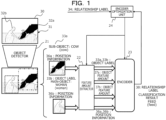
- FIG. 1 is a diagram describing a training process on an encoder 23 in a technology in the related art.
- the encoder 23 is trained with supervised learning using a deep neural network (DNN).
- DNN deep neural network
- the labeled data 30 includes image data 31.
- a plurality of target objects 32a (cow) and 32b (woman) exist in the image data 31.
- the labeled data 30 may include object labels 33a and 33b, and a relationship label 34.
- the object labels 33a and 33b are information indicating a type (class) of each of the plurality of target objects 32a and 32b in the image data 31.
- the object label 33a is "cow”
- the object label 33b is "woman”.
- the relationship label 34 is information indicating a relationship between the plurality of target objects 32a and 32b, and is "feed” in FIG. 1 .
- a trained object detector 21 acquires the object labels 33a and 33b and position information 36a and 36b of the respective target objects 32a and 32b, from the labeled data 30.
- the target objects 32a and 32b may include a main-object and a sub-object.
- the object label 33a and the position information 36a are acquired for the "cow” which is a sub-object.
- the object label 33b and the position information 36b are acquired for the " woman" which is a main-object.
- a feature amount extractor 22 calculates a first object feature amount 37a for the target object 32a (sub-object) and a first object feature amount 37b for the target object 32b (main-object) based on the position information 36a and 36b occupied by the target objects 32a and 32b, respectively.
- the encoder 23 outputs a classification result 38 of a relationship label based on the first object feature amount 37a of the sub-object and the first object feature amount 37b of the main-object.
- the encoder 23 outputs the classification result 38 of the relationship label "feed".
- An encoder optimization unit 24 compares the classification result 38 of the relationship label output from the encoder 23 with the relationship label 34 as a correct answer of the labeled data 30, and trains the encoder 23 to reduce an error between the classification result 38 and the relationship label 34.
- a method of considering the specific relationship by increasing a variation of the labeled data 30 can be considered. Meanwhile, increasing the number of pieces of data of the labeled data 30 having the relationship label 34 increases a burden on an operator.
- FIG. 2 is a block diagram schematically illustrating a hardware configuration example of an information processing apparatus 1 according to the embodiment.
- the information processing apparatus 1 is a computer. As illustrated in FIG. 2 , the information processing apparatus 1 includes a processor 11, a memory unit 12, a display control unit 13, a storage device 14, an input interface (IF) 15, an external recording medium processing unit 16, and a communication IF 17.
- a processor 11 a processor 11, a memory unit 12, a display control unit 13, a storage device 14, an input interface (IF) 15, an external recording medium processing unit 16, and a communication IF 17.
- the memory unit 12 is an example of a storage unit, and is, for example, a read-only memory (ROM), a random-access memory (RAM), or the like.
- a program such as a Basic Input/Output System (BIOS) may be written in the ROM of the memory unit 12.
- BIOS Basic Input/Output System
- a software program of the memory unit 12 may be appropriately read into and executed by the processor 11.
- the RAM of the memory unit 12 may be used as a temporary recording memory or a working memory.
- the display control unit 13 is coupled to a display device 130, and controls the display device 130.
- the display device 130 is a liquid crystal display, an organic light-emitting diode (OLED) display, a cathode ray tube (CRT), an electronic paper display, or the like, and displays various types of information for an operator or the like.
- the display device 130 may be combined with an input device, or may be, for example, a touch panel.
- the storage device 14 is a storage device having high IO performance, and for example, dynamic random-access memory (DRAM), a solid-state drive (SSD), a storage class memory (SCM), or a hard disk drive (HDD) may be used.
- DRAM dynamic random-access memory
- SSD solid-state drive
- SCM storage class memory
- HDD hard disk drive
- the input IF 15 may be coupled to an input device, such as a mouse 151 or a keyboard 152, and may control the input device, such as the mouse 151 or the keyboard 152.
- the mouse 151 and the keyboard 152 are examples of the input devices, and the operator performs various input operations via these input devices.
- the external recording medium processing unit 16 is configured such that a recording medium 160 can be mounted.
- the external recording medium processing unit 16 is configured such that information recorded on the recording medium 160 can be read in a state in which the recording medium 160 is mounted.
- the recording medium 160 has portability.
- the recording medium 160 is a flexible disk, an optical disk, a magnetic disk, an optical magnetic disk, a semiconductor memory, or the like.
- the communication IF 17 is an interface for enabling communication with an external apparatus.
- the processor 11 is a processing device that performs various types of control and computation.
- the processor 11 may include a central processing unit (CPU).
- the processor 11 may include a discrete graphics processing unit (dGPU), and the dGPU means a GPU that exists over a graphic chip or a graphic board that is independent of the CPU.
- the processor 11 realizes various functions by executing an operating system (OS) or a program read in the memory unit 12.
- the processor 11 may realize a function as a control unit 100, which will be described below.
- a device for controlling the operation of the entire information processing apparatus 1 is not limited to the CPU and the dGPU, and may be, for example, any one of an MPU, a DSP, an ASIC, a PLD, and an FPGA.
- the device for controlling the operation of the entire information processing apparatus 1 may be a combination of two or more types of the CPU, the MPU, the DSP, the ASIC, the PLD, and the FPGA.
- the MPU is an abbreviation for a micro processing unit
- the DSP is an abbreviation for a digital signal processor
- the ASIC is an abbreviation for an application-specific integrated circuit.
- PLD is an abbreviation for a programmable logic device
- FPGA is an abbreviation for a field-programmable gate array.
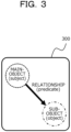
- FIG. 3 is a diagram describing a definition of a scene graph 300.
- the scene graph 300 is a directed graph in which objects (target objects) in an image or a moving image are represented by nodes and a relationship between the target objects is represented by an edge.
- the image and the moving image are examples of image data.
- the target object (object) may be a living organism including a person, an article, or a part of the living organism or the article.
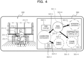
- FIG. 4 is a diagram schematically illustrating an example of the scene graph 300.
- a data set illustrated in FIG. 4 includes image data 200 and the scene graph 300.
- a man, a computer, a table, a chair, and a window exist as target objects in the image data 200.
- Position information 211-1 to 211-5 of the respective target objects are given.
- the position information 211 may have information on coordinates (x, y), a height, and a width.
- the position information 211 may be represented by a bounding box.
- the bounding box is a rectangular box surrounding the target object.
- the scene graph 300 includes an object label 321-1 (man), an object label 321-2 (computer), an object label 321-3 (table), an object label 321-4 (chair), and an object label 321-5 (window).
- object label 321-1 man
- object label 321-2 computer
- object label 321-3 table
- object label 321-4 chair
- object label 321-5 windshield
- directed edges 323-1 to 328-4 may be a line with an arrow.
- a relationship label 322-1 is illustrated to be "using”.
- a relationship label 322-2 between the computer and the table is illustrated to be “on”, and a relationship label 322-3 between the man and the chair is illustrated to be “sitting on”.
- the relationship label 322 can increase the information amount of the scene graph 300 by indicating a specific relationship (for example, sitting on or standing on) rather than an abstract relationship (for example, on).
- the information processing apparatus 1 improves classification accuracy of the relationship by reflecting the specific relationship between a plurality of target objects in the image data. For this reason, the information processing apparatus 1 uses self-supervised learning, particularly, a contrastive learning method.
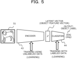
- FIG. 5 is a diagram illustrating an example of self-supervised learning.
- FIG. 5 as a simple example, a case is described in which image data in which a dog appears is input as input data 51, and an object label "dog" is output as output.
- the encoder 43 In a case where the input data 51 is input to an encoder 43, the encoder 43 outputs a latent vector (in FIG. 5 , an object feature vector) Z.
- the latent vector Z is input to a classifier 44, and the classifier 44 outputs a label.
- the self-supervised learning has a two-stage training (learning) step.
- the encoder 43 is trained by using unlabeled data.
- the unlabeled data has a smaller generation burden than labeled data. Therefore, the number of pieces of data can be increased in a case of training using the unlabeled data, as compared with a case of training using the labeled data. Therefore, the encoder 43 can learn many variations, and can increase training accuracy (learning accuracy).
- FIG. 6 is a diagram illustrating an example of contrastive learning.
- the contrastive learning is a kind of self-supervised learning.
- FIG. 6 as a simple example, a case is described in which image data in which a dog appears is input as the input data 51, and an object label "dog" is output as an output.
- Two pieces of extension data x i to T 1 (x) and x j to T 2 (x) are obtained from an input x (the input data 51) by two types of data extension (T 1 , T 2 ).
- the data extension is obtained, for example, by executing deformation by parallel movement, rotation, enlargement and reduction, up and down inversion, left and right inversion, brightness adjustment, and a combination of a plurality of these on an original image.
- the two pieces of extension data x i to T 1 (x) and x j to T 2 (x) are data on which different deformations are performed without changing the essence of the object.
- a loss function L ⁇ -sim(z i , z j ) is calculated, and a parameter ⁇ may be updated such that this value is minimized.
- the encoder 143 is an example of an encoder that calculates a relationship between a plurality of target objects.
- FIG. 7 is a block diagram schematically illustrating a first example of a software configuration in a training phase of an encoder by the information processing apparatus 1 illustrated in FIG. 2 .
- the control unit 100 may include a labeled data acquisition unit 101, an object label acquisition unit 102, a position information acquisition unit 103, a detection certainty factor acquisition unit 104, a first object feature amount acquisition unit 105, a pair creation unit 106, an unlabeled data acquisition unit 108, a second object feature amount acquisition unit 109, and an encoder optimization unit 110.
- the control unit 100 realizes a learning process (training process) in machine learning using training data. That is, the information processing apparatus 1 functions as a training apparatus that trains a machine learning model by the control unit 100.
- an object detector 121, an object feature amount extractor 122, and the encoder 143 are examples of the machine learning model.
- the machine learning model may be, for example, a deep learning model (deep neural network).
- the neural network may be a hardware circuit, or may be a virtual network by software that is coupled to a hierarchy virtually constructed over a computer program by the processor 11 or the like.
- the labeled data acquisition unit 101 acquires the labeled data 30.
- the labeled data 30 may be a data set including image data, an object label, and a relationship label.
- the acquired labeled data 30 may be input to the object detector 121.
- the object detector 121 may be an existing object detector based on a DNN.
- the object detector 121 may be a faster region-based convolutional neural network (FasterRCNN) or may be a detection transformer (DETR). A detailed description of the object detector 121 itself will be omitted.
- the object label acquisition unit 102 respectively acquires the object labels 33a and 33b of the target objects 32a and 32b in image data from the labeled data 30.
- the labeled data 30, the image data 31, the target objects 32a and 32b, the object labels 33a and 33b, the relationship label 34, the position information 36a and 36b, and the object feature amounts 37a and 37b may be the same as the technology in the related art illustrated in FIG. 1 .
- the position information acquisition unit 103 acquires the position information 36a and 36b of the respective target objects 32a and 32b in the image data 31.
- the position information acquisition unit 103 acquires the position information 36a and 36b by using the object detector 121.
- the first object feature amount acquisition unit 105 acquires the first object feature amounts 37a and 37b, which are object feature amounts for the target objects 32a and 32b, based on the position information 36a and 36b.
- the first object feature amounts 37a and 37b are examples of a first object feature amount.
- the position information 36a and 36b specified by the object detector 121 are input to the object feature amount extractor 122, respectively.
- the object feature amount extractor 122 specifies the object feature amounts 37a and 37b, based on image data in the bounding boxes, which are the position information 36a and 36b.
- the object detector 121 and the object feature amount extractor 122 may be formed as one machine learning model.
- the first object feature amount acquisition unit 105 may acquire the object feature amounts 37a and 37b by using the object feature amount extractor 122.
- the unlabeled data acquisition unit 108 may extract an image including the same label from an external data set, by using any of an object label of any of the main-object and the sub-object as a key.
- the unlabeled data 39 is data that does not have a relationship label between the plurality of target objects.
- the unlabeled data acquisition unit 108 can acquire image data classified into the same class "cow" as the target object 32a, that is, image data of the cow.
- the unlabeled data acquisition unit 108 can widely acquire a large amount of unlabeled data 39 from an outside of the information processing apparatus 1 via the Internet.
- the second object feature amount acquisition unit 109 acquires a second object feature amount 40, which is an object feature amount for the object in the unlabeled data 39.
- the second object feature amount 40 is an example of a second object feature amount.
- the second object feature amount acquisition unit 109 acquires the second object feature amount 40 based on image data in a bounding box corresponding to an object in the unlabeled data 39.
- the second object feature amount acquisition unit 109 may acquire the second object feature amount 40 by using the object detector 121 and the object feature amount extractor 122.
- the control unit 100 acquires first data including the first object feature amount 37a of the sub-object, the first object feature amount 37b of the main-object, the position information 36a of the sub-object, and the position information 36b of the main-object, by the position information acquisition unit 103 and the first object feature amount acquisition unit 105.
- the control unit 100 generates second data in which at least one of the first object feature amount 37a of the sub-object and the first object feature amount 37b of the main-object in the first data is substituted with another second object feature amount 40 by the position information acquisition unit 103 and the second object feature amount acquisition unit 109.
- the control unit 100 trains the encoder 143 by inputting the second data as extension data during encoder training using contrastive learning.
- the encoder 143 may be configured with a multilayer perceptron (MLP), for example.
- MLP multilayer perceptron
- the encoder 143 is configured with at least three node layers.
- the training (learning) of the encoder 143 may be performed by using a learning method called backpropagation (error backpropagation method).
- the encoder optimization unit 110 may acquire a first latent vector 62a (Z) for a relationship between the plurality of target objects 32a and 32b, which is obtained by inputting the first data to the encoder 143.
- the encoder optimization unit 110 may acquire a second latent vector 62b (Z') for a relationship between the plurality of target objects 32a and 32b, which is obtained by inputting the second data to the encoder 143.
- the encoder optimization unit 110 may train the encoder 143 with machine learning to increase a coincidence degree (similarity) between the first latent vector 62a (Z) and the second latent vector 62b (Z').
- the first latent vector 62a (Z) is an example of a first relationship feature amount for the relationship between the plurality of target objects 32a and 32b
- the second latent vector 62b (Z) is an example of a second relationship feature amount for the relationship between the plurality of target objects 32a and 32b.
- a function used as a criterion for evaluating the coincidence degree (similarity) may be a function used in contrastive learning (SimCLR or the like) (InforNCE or the like).
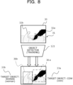
- FIG. 8 is a diagram illustrating an example of a training process of the object detector 121 by the information processing apparatus 1 illustrated in FIG. 2 .
- the image data 31 and the labeled data 30 including a correct answer label and correct answer position information for the object labels 33a and 33b of the target objects 32a and 32b in the image data 31 are input to the object detector 121.
- the labeled data 30 may be a data set such as visual genome in the example.
- the object detector 121 respectively outputs the object labels 33a and 33b and the position information 36a and 36b of the target objects 32a and 32b, based on the image data 31.
- the object detector 121 may also output the detection certainty factor as described in FIG. 7 .
- the position information 36a and 36b may have information on plane coordinates (x, y), a height (h), and a width (w).
- the plane coordinates may be coordinates of one vertex of a bounding box (rectangle).
- the height (h) may be a length of a side of the bounding box in an x-direction
- the width (w) may be a length of a side of the bounding box in a y-direction parallel with the x-direction.
- FIG. 9 is a diagram illustrating an example of a training process of the encoder 143 by the information processing apparatus 1 illustrated in FIG. 2 .
- a parameter of the object detector 121 is fixed.
- a case where the parameter of the object detector 121 is fixed is referred to as "freezing" in some cases.
- Second data in which at least one of the first object feature amount 37a of the sub-object or the first object feature amount 37b of the main-object is substituted with the second object feature amount 40 is generated from first data including the first object feature amount 37a of the sub-object (not illustrated in FIG. 9 ), the first object feature amount 37b of the main-object, the position information 36a of the sub-object, and the position information 36b of the main-object.
- FIG. 9 a case is illustrated in which second data 42 is generated by substituting the first object feature amount 37a with the second object feature amount 40, and the first object feature amount 37b may be substituted with the second object feature amount 40.
- both the first object feature amount 37a and the first object feature amount 37b may be substituted with the second object feature amount 40.
- the unlabeled data 39 which does not include a relationship label can be used.
- the unlabeled data 39 may be image data (image data of a cow and image data of a woman) classified into at least one class (a cow, a woman, or the like) of the target object 32a or the target object 32b. Therefore, an external data set that can be used as the unlabeled data 39 exists in a large amount in the Internet space. Therefore, the encoder 143 can be trained (learned) by using the large amount of data without the relationship label.
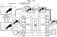
- FIG. 10 is a diagram illustrating an example of a process of using contrastive learning in a training process of the encoder 143 in FIG. 9 .
- first data 41 including the first object feature amount 37a of the sub-object, the first object feature amount 37b of the main-object, the position information 36a of the sub-object, and the position information 36b of the main-object, and the second data 42 in which the first object feature amount 37a is substituted with the second feature amount 40 are input to the encoder 143.
- the encoder 143 outputs the first latent vector 62a (the relationship feature vector Z) based on the input of the first data 41.
- the encoder 143 outputs the second latent vector 62b (the relationship feature vector Z') based on the input of the second data 42.
- the second latent vector 62b (Z') is obtained by data extension of the first data 41, which is the input to the encoder 143.
- the position information 36a and 36b are the same as the first data 41, which is an original input.
- a class of another object in the second data 42 (for example, the cow) is the same as a class of the sub-object (the target object 32a) in the first data 41.
- the object feature amount of the target object 32b, which is the main-object in the second data 42, is the same as the object feature amount of the target object 32b in the first data 41. Therefore, an essential portion (the position information and the object label) of the relationship between the target objects in the first data 41 and the relationship between the target objects in the second data 42 are maintained.
- the first latent vector 62a (the relationship feature vector Z) and the second latent vector 62b (the relationship feature vector Z') are to be similar to each other. Contrastive learning is performed on the encoder 143 such that the coincidence degree (similarity) between the first latent vector 62a (Z) and the second latent vector 62b (Z') is increased.
- FIG. 11 is a block diagram schematically illustrating a second example of the software configuration in the training phase of the encoder 143 by the information processing apparatus 1 illustrated in FIG. 2 .
- Second data and third data may be generated from the first data 41 by two types of data extension, in the same manner in which the two pieces of extension data are obtained from the input x by two types of data extension (T1, T2), in the description with reference to FIG. 6 .
- a second and third object feature amount acquisition unit 111 is provided, instead of the second object feature amount acquisition unit 109 in FIG. 7 .
- control unit 100 generates the second data 42 as data in which at least one of the first object feature amount 37a of the sub-object or the first object feature amount 37b of the main-object is substituted with the other second object feature amount 40 corresponding to the main-object or the sub-object, in the first data 41.
- the generation of the third object feature amount 54 and the third data 53 has the same manner as the generation of the second object feature amount 40 and the second data 42.
- the unlabeled data 39 without a relationship label can be used without being restricted by the number of pieces of data of the labeled data 30.
- the number of pieces of data for training the encoder 143 can be increased.
- FIG. 12 is a block diagram schematically illustrating an example of a software configuration in a training phase of a classifier 144 by the information processing apparatus 1 illustrated in FIG. 2 .
- a state is illustrated in which training of the object detector 121 and the encoder 143 is completed and a parameter is fixed.
- the control unit 100 may include the labeled data acquisition unit 101, the object label acquisition unit 102, the position information acquisition unit 103, the first object feature amount acquisition unit 105, the pair creation unit 106, and a classifier optimization unit 112.
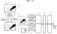
- FIG. 13 is a diagram illustrating an example of a training process of the classifier 144 by the information processing apparatus 1 illustrated in FIG. 2 .
- the first object feature amount 37a of a sub-object, the first object feature amount 37b of a main-object, the position information 36a of the sub-object, and the position information 36b of the main-object are acquired.
- Each of the acquired data is input to the encoder 143.
- the classifier 144 is used as an example of a machine learning model.
- the classifier 144 may be, for example, a deep learning model (deep neural network).
- the neural network may be a hardware circuit, or may be a virtual network by software that is coupled to a hierarchy virtually constructed over a computer program by the processor 11 or the like.
- the classifier 144 may be logistic regression, which is an identification model configured with only one fully coupled layer, or may be a multilayer perceptron (MLP) having a plurality of layers.
- MLP multilayer perceptron
- the control unit 100 acquires the first object feature amount 37a of the sub-object, the first object feature amount 37b of the main-object, the position information 36a of the sub-object, and the position information 36b of the main-object, by the position information acquisition unit 103 and the first object feature amount acquisition unit 105. Each of the acquired data is input to the encoder 143.
- the control unit 100 calculates a latent vector 62 (Z) by using the encoder 143.
- the latent vector Z indicates a position in a latent space.
- the latent vector 62 (Z) is input to the classifier 144.
- the classifier 144 outputs a logit.
- the logit may be a non-normalized final score for classification of a relationship label.
- the logit may be converted into a prediction value of the relationship label by using a Softmax function or the like.
- the classifier optimization unit 112 optimizes a parameter of the classifier 144, based on a correct answer label and the logit of the relationship label in the labeled data 30.
- the number of pieces of data is increased by using the unlabeled data 39, while in the training of the classifier 144, the unlabeled data 39 may not be used.
- FIG. 14 is a block diagram schematically illustrating an example of a software configuration in an inference phase by the information processing apparatus 1 illustrated in FIG. 2 .
- the control unit 100 may include the object label acquisition unit 102, the position information acquisition unit 103, the first object feature amount acquisition unit 105, the pair creation unit 106, an input image acquisition unit 113, a relationship label acquisition unit 114, and a scene graph creation unit 115.
- the object label acquisition unit 102, the position information acquisition unit 103, the first object feature amount acquisition unit 105, and the pair creation unit 106 may have the same functions as the functions described using FIG. 7 , except that data as a processing target is input image data, instead of the labeled data 30 for training.
- the input image acquisition unit 113 acquires the input image data, which is a processing target.
- the input image data of the processing target is input to the trained object detector 121.
- the object detector 121 is used to acquire object labels and position information of target objects (main-object and sub-object) in the input image data.
- the object feature amounts of the target objects (main-object and sub-object) are acquired by using the object feature amount extractor 122.
- the encoder 143 receives the position information and the object feature amounts of the target objects (main-object and sub-object) in the input image data.
- the encoder 143 infers the latent vector 62 (Z) based on the position information and the object feature amounts of the target objects (main-object and sub-object).
- the latent vector 62 (relationship feature vector) indicates a relationship between a plurality of target objects (between the sub-object and the main-object).
- the latent vector 62 is input to the classifier 144.
- the classifier 144 outputs a logit in the example.
- the relationship label acquisition unit 114 acquires a relationship label indicating the relationship between the plurality of target objects (sub-object and main-object) by using a logit.
- the scene graph creation unit 115 creates the scene graph 300.
- the scene graph creation unit 115 collects the object labels of the main-object and the sub-object acquired from the input image data by the object label acquisition unit 102, and the relationship labels of the main-object and the sub-object acquired from the input image data by the relationship label acquisition unit 114 as the scene graph 300.
- data extension is performed by replacing the object feature amount of at least one of the main-object or the sub-object in the first data 41 with the object feature amount of another object of the same class.
- the encoder 143 can learn many variations, and can increase training accuracy.
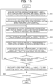
- the control unit 100 acquires the position information 36a and 36b (B) of the target objects 32a and 32b in image data, the object labels 33a and 32b (L), a detection certainty factor C, and the first object feature amounts 37a and 37b (H) from the input labeled data 30 (x) (step S11).
- the control unit 100 acquires each value by inputting the labeled data 30 to the object detector 121 (od).
- the first object feature amounts 37a and 37b (H) are acquired by using the object feature amount extractor 122.
- the input x is defined as x ⁇ labeled data (image data set) Di.
- the first object feature amount H (h 1 , h 2 , ..., h i , ..., and h N ) od(x)
- the detection certainty factor C and the pair upper limit count Nmax are input to the pair creation unit 106 (PairGenerator).
- the pair creation unit 106 generates a pair P of a main-object and a sub-object from target objects 32 (step S12).
- the control unit 100 generates the pair P of the main-object and the sub-object from among the plurality of target objects 32 (step S12).
- the first object feature amounts h si and h oi of the main-object and the sub-object and the position information b si and b oi are input to the encoder 143.
- the first latent vector 62a which is a feature vector Z i , is calculated from the encoder 143 (f ⁇ ) (step S13).
- the first object feature amounts h si and h oi of the main-object and the sub-object and the position information b si and b oi are examples of first data.
- the unlabeled data acquisition unit 108 extracts an image Xe (the unlabeled data 39) including another object corresponding to l si from an external data set De, by using the object label l si of the main-object as a key (step S14). Meanwhile, the unlabeled data acquisition unit 108 may extract the image Xe (the unlabeled data 39) including still another object corresponding to l oi from the external data set De, by using the object label l oi of the sub-object as a key.
- the second object feature amount acquisition unit 109 inputs the image Xe (unlabeled data 39) to the object detector 121 (od), and extracts the second object feature amount 40 (h' si ) corresponding to the object label l si in the image Xe from an output of the object detector 121 (od) (step S15).
- the second object feature amount acquisition unit 109 may select the second object feature amount 40 (h' si ) at random.
- the control unit 100 inputs the second object feature amount 40 (h' si ), the first object feature amount (h oi ), and the position information b si and b oi to the encoder 143 (f ⁇ ) as the object feature amounts of the main-object and the sub-object.
- the control unit 100 calculates the second latent vector 62b, which is the feature vector Z i , based on an output of the encoder 143 (f ⁇ ) (step S16).
- the second object feature amount 40 (h' si ), the first object feature amount (h oi ), and the position information b si and b oi are examples of the second data 42.
- the second data 42 is data in which at least one of the first object feature amount h si or h oi in the first data 41 is substituted. Meanwhile, the second data 42 maintains the position information b si and b oi in the first data 41.
- a first latent vector Zi f ⁇ (h si , h oi , b si , b oi )
- a first latent vector Z'i f ⁇ (h' si , h oi , b si , b oi )
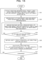
- the control unit 100 determines whether or not the calculation of the feature vector is completed for all the pairs (step S17). In a case where the feature vector is not calculated for all the pairs (see No route in step S17), the process may return to the process of step S13. In a case where the calculation of the feature vector is completed for all the pairs (see Yes route of step S17). The process proceeds to step S18.
- the encoder optimization unit 110 calculates a loss function E x ⁇ p(x) [-sim(Z, Z')], and updates a parameter ⁇ such that the value thereof is minimized (step S18).
- argmin means a function for acquiring the parameter ⁇ that gives the minimum value.
- the control unit 100 repeats the process of steps S11 to S19 until the process converges (see No route in step S19).
- the control unit 100 waits for the process to converge (see Yes route of step S19), and ends the training process of the encoder 143 in the training phase.
- Step S21 is the same as step S11 in FIG. 15 .
- the position information B is input to the pair creation unit 106 (PairGenerator).
- the pair creation unit 106 generates the pair P of a main-object and a sub-object from the target objects 32 (step S22).
- s i represents an index of the main-object of the i-th pair
- o i represents an index of the sub-object of the i-th pair
- the control unit 100 generates the pair P of the main-object and the sub-object from among the plurality of target objects 32 (step S12).
- the first object feature amounts h si and h oi of the main-object and the sub-object and the position information b si and b oi are input to the encoder 143.
- the latent vector 62 (feature vector) that is the feature vector Z i is calculated from the encoder 143 (f ⁇ ) (step S23).
- a latent vector Zi f ⁇ (h si , h oi , b si , b oi )
- step S24 In a case where there is a pair P for which the latent vector (feature vector) is not calculated (No route of step S24), the process returns to step S23.
- the feature vector Z is input to the classifier 144 (g ⁇ ) after waiting for the calculation of the latent vector (feature vector) for all the pairs P (Yes route of step S24).
- a logit Y is calculated from an output of the classifier 144 (g ⁇ ) (step S25).
- the classifier optimization unit 112 calculates the loss function E x ⁇ p(x) based on the following expression.
- ⁇ argmin(E x ⁇ p(x) [CrossEntropy(Softmax(Y), T]).
- T is a correct answer relationship label.
- the logit Y is converted into a prediction value of class classification of the relationship label by using the Softmax function or the like.
- a distance between the prediction value and the correct answer relationship label is calculated by the CrossEntropy function.
- the parameter ⁇ is updated by the argmin function such that the distance between the prediction value and the correct answer relationship label is minimized (step S26).
- the control unit 100 repeats the process of steps S21 to S27 until the process converges (see No route of step S27).
- the control unit 100 waits for the process to converge (see Yes route of step S27), and ends the training process of the classifier 144 in the training phase.
- the input image acquisition unit 113 acquires input image data (input image x) of a processing target.
- the process of steps S31 to S35 has the same manner as the process of steps S21 to 25 of FIG. 16 , except for a difference in the input data.
- the relationship label acquisition unit 114 calculates a softmax value softmax(Y) of the logit Y to extract a relationship label corresponding to an index (subscript) with which a value of softmax(Y) is the largest (step S36).
- the scene graph creation unit 115 creates the scene graph 300 for the input image by collecting an object label and a relationship label constituting each pair (step S37). In a case where the process is not collected, the process returns to step S31 (see No route of step S38). The control unit 100 waits for the process to be collected (see Yes route of step S38), and the creation process of the scene graph in the inference phase is completed.
- FIG. 18 is a diagram illustrating an example of a result of a reproducibility of a relationship label by the information processing apparatus 1 illustrated in FIG. 2 .
- a reproducibility which is the degree to which the encoder 143 can reproduce a correct relationship label, is high in a case of an abstract relationship and is low in a case of a specific relationship.
- contrastive learning a reproducibility of a relationship label can be further improved even in the case of the specific relationship, and a bias of class distribution of the relationship label is relaxed.
- the reproducibility of the specific relationship label can be enhanced, as compared with a case of the technology in the related art. Therefore, in a case of creating the scene graph 300, the scene graph 300 having improved expression power can be created.
- the control unit 100 acquires the first data 41 including each of the first object feature amounts 37a and 37b and the position information 36a and 36b of the plurality of target objects 32a and 32b in first image data.
- the control unit 100 generates at least one second data 42 by substituting at least one of the first object feature amounts 37a and 37b of the plurality of target objects 32a and 32b in the first data 41 with the second object feature amount 40.
- the second object feature amount 40 is an object feature amount acquired for at least one other object classified into the same class as the target object in at least one second image data different from the first image data.
- the control unit 100 inputs at least one of the second data 42 to the encoder 143 to train the encoder 143.
- classification accuracy of the relationship can be improved by reflecting the specific relationship between the plurality of target objects 32a and 32b in the image data.
- control unit 100 inputs the first data 41 and the second data 42 to the encoder 143 to train the encoder 143.
- the existing labeled data 30 can be used as training data of the encoder 143, and the unlabeled data 39 can be acquired and used. Therefore, the encoder 143 can be trained by the training data having a variety. Therefore, training accuracy is increased.
- the control unit 100 performs machine learning to increase a coincidence degree between the first relationship feature amount (first latent vector Z) and the second relationship feature amount (second latent vector Z').
- the first relationship feature amount is a feature amount related to a relationship between the plurality of target objects 32a and 32b, and is obtained by inputting the first data 41 to the encoder 143.
- the second relationship feature amount is a feature amount related to a relationship between the plurality of target objects 32a and 32b, and is obtained by inputting the second data 42 to the encoder 143.
- the control unit 100 acquires the first object feature amounts 37a and 37b and the position information 36a and 36b by inputting the first image data to the trained object detector 121.
- the control unit 100 acquires the second object feature amount 40 by inputting the second image data to the trained object detector 121.
- classification accuracy of the relationship can be improved by reflecting the specific relationship between the plurality of target objects 32a and 32b in the image data.
Landscapes
- Engineering & Computer Science (AREA)
- Theoretical Computer Science (AREA)
- Physics & Mathematics (AREA)
- General Physics & Mathematics (AREA)
- Computer Vision & Pattern Recognition (AREA)
- Artificial Intelligence (AREA)
- Computing Systems (AREA)
- Health & Medical Sciences (AREA)
- Evolutionary Computation (AREA)
- General Health & Medical Sciences (AREA)
- Software Systems (AREA)
- Databases & Information Systems (AREA)
- Medical Informatics (AREA)
- Multimedia (AREA)
- Life Sciences & Earth Sciences (AREA)
- Biomedical Technology (AREA)
- Biophysics (AREA)
- Computational Linguistics (AREA)
- Data Mining & Analysis (AREA)
- Molecular Biology (AREA)
- General Engineering & Computer Science (AREA)
- Mathematical Physics (AREA)
- Image Analysis (AREA)
Abstract
Description
- The present invention relates to a training program, a training method, and an information processing apparatus.
- A technology of generating a knowledge graph called a scene graph from image data is known. The scene graph includes information on a relationship between a plurality of target objects in the image data. In a case of generating the scene graph, a machine learning model for calculating the feature amount of the relationship between the target objects is trained by using supervised data (labeled data) including a correct answer label for the relationship between the target objects. From the viewpoint of increasing the information amount included in the scene graph, it is desirable to calculate a specific relationship rather than an abstract relationship between the plurality of target objects.
- PTL 1:
Japanese National Publication of International Patent Application No. 2022-508737 - Meanwhile, depending on a content of the prepared supervised data (labeled data), there is a concern that it is not easy to improve classification accuracy of the relationship by reflecting the specific relationship between the objects.
- In one aspect, an object is to improve classification accuracy of a relationship by reflecting a specific relationship between a plurality of target objects in image data.
- In one aspect, a training program causes a computer to execute a process including: generating, for first data that includes a first object feature amount and position information of each of a plurality of target objects in first image data, at least one second data by substituting at least one first object feature amount of the plurality of target objects with a second object feature amount acquired for at least one other object classified into a same class as the target object in at least one second image data that is different from the first image data; and training an encoder by inputting the at least one second data to the encoder.
- In one aspect, it is possible to improve classification accuracy of a relationship by reflecting a specific relationship between a plurality of target objects in image data.
-
- [
FIG. 1] FIG. 1 is a diagram describing a training process of an encoder in a technology in the related art. - [
FIG. 2] FIG. 2 is a block diagram schematically illustrating a hardware configuration example of an information processing apparatus according to an embodiment. - [
FIG. 3] FIG. 3 is a diagram describing a definition of a scene graph. - [
FIG. 4] FIG. 4 is a diagram schematically illustrating an example of the scene graph. - [
FIG. 5] FIG. 5 is a diagram illustrating an example of self-supervised learning. - [
FIG. 6] FIG. 6 is a diagram illustrating an example of contrastive learning. - [
FIG. 7] FIG. 7 is a block diagram schematically illustrating a first example of a software configuration in a training phase of the encoder by the information processing apparatus illustrated inFIG. 2 . - [
FIG. 8] FIG. 8 is a diagram illustrating an example of a training process of an object detector by the information processing apparatus illustrated inFIG. 2 . - [
FIG. 9] FIG. 9 is a diagram illustrating an example of a training process of the encoder by the information processing apparatus illustrated inFIG. 2 . - [
FIG. 10] FIG. 10 is a diagram illustrating an example of a process of using contrastive learning in the training process of the encoder inFIG. 9 . - [
FIG. 11] FIG. 11 is a block diagram schematically illustrating a second example of the software configuration in the training phase of the encoder by the information processing apparatus illustrated inFIG. 2 . - [
FIG. 12] FIG. 12 is a block diagram schematically illustrating an example of a software configuration in a training phase of a classifier by the information processing apparatus illustrated inFIG. 2 . - [
FIG. 13] FIG. 13 is a diagram illustrating an example of a training process of the classifier by the information processing apparatus illustrated inFIG. 2 . - [
FIG. 14] FIG. 14 is a block diagram schematically illustrating an example of a software configuration in an inference phase by the information processing apparatus illustrated inFIG. 2 . - [
FIG. 15] FIG. 15 is a flowchart describing an example of a training process of the encoder in the training phase of the information processing apparatus illustrated inFIG. 2 . - [
FIG. 16] FIG. 16 is a flowchart describing an example of a training process of the classifier in the training phase of the information processing apparatus illustrated inFIG. 2 . - [
FIG. 17] FIG. 17 is a flowchart illustrating an example of a creation process of a scene graph in the inference phase of the information processing apparatus illustrated inFIG. 2 . - [
FIG. 18] FIG. 18 is a diagram illustrating an example of a result of a reproducibility of a relationship label by the information processing apparatus illustrated inFIG. 2 . -
FIG. 1 is a diagram describing a training process on anencoder 23 in a technology in the related art. - In the technology in the related art, the
encoder 23 is trained with supervised learning using a deep neural network (DNN). - As input image data, labeled
data 30 is used. The labeleddata 30 is also referred to as supervised data. - The labeled
data 30 includesimage data 31. In an example illustrated inFIG. 1 , a plurality oftarget objects 32a (cow) and 32b (woman) exist in theimage data 31. The labeleddata 30 may includeobject labels relationship label 34. Theobject labels target objects image data 31. InFIG. 1 , theobject label 33a is "cow", and theobject label 33b is "woman". Therelationship label 34 is information indicating a relationship between the plurality oftarget objects FIG. 1 . - A trained
object detector 21 acquires theobject labels position information respective target objects data 30. Thetarget objects object label 33a and theposition information 36a are acquired for the "cow" which is a sub-object. In the same manner, theobject label 33b and theposition information 36b are acquired for the "woman" which is a main-object. - A
feature amount extractor 22 calculates a firstobject feature amount 37a for thetarget object 32a (sub-object) and a firstobject feature amount 37b for thetarget object 32b (main-object) based on theposition information target objects - The
encoder 23 outputs aclassification result 38 of a relationship label based on the firstobject feature amount 37a of the sub-object and the firstobject feature amount 37b of the main-object. In the present example, theencoder 23 outputs theclassification result 38 of the relationship label "feed". Anencoder optimization unit 24 compares theclassification result 38 of the relationship label output from theencoder 23 with therelationship label 34 as a correct answer of the labeleddata 30, and trains theencoder 23 to reduce an error between theclassification result 38 and therelationship label 34. - In the technology in the related art, it is necessary to prepare the labeled
data 30. In a case where the prepared labeleddata 30 has a bias in therelationship label 34 as the correct answer, it is not easy to increase training accuracy of theencoder 23. In the example, there is a case where an appearance frequency of an abstract relationship such as "on" or "have" is higher than an appearance frequency of a specific relationship such as "sitting on" or "walking on". In this case, it is not easy to assign a relationship label in consideration of the specific relationship. - A method of considering the specific relationship by increasing a variation of the labeled
data 30 can be considered. Meanwhile, increasing the number of pieces of data of the labeleddata 30 having therelationship label 34 increases a burden on an operator. - In that respect, it is considered to adopt self-supervised learning in which the
encoder 23 is trained by using not only the labeleddata 30 but also unlabeled data, particularly, contrastive learning. - Hereinafter, an embodiment will be described with reference to the drawings. Meanwhile, the following embodiment is merely an example, and the intention is not to exclude various modification examples and the application of the technology not described in the embodiment. That is, the present embodiment can be implemented with various modifications without departing from spirit of the present embodiment. In addition, the present embodiment is not limited to the components illustrated in each of the drawings, and the components can include other functions or the like.
- Hereinafter, in the drawings, the same respective reference numerals denote the same portions, and the description thereof will be omitted.
-
FIG. 2 is a block diagram schematically illustrating a hardware configuration example of aninformation processing apparatus 1 according to the embodiment. - The
information processing apparatus 1 is a computer. As illustrated inFIG. 2 , theinformation processing apparatus 1 includes aprocessor 11, amemory unit 12, adisplay control unit 13, astorage device 14, an input interface (IF) 15, an external recordingmedium processing unit 16, and a communication IF 17. - The
memory unit 12 is an example of a storage unit, and is, for example, a read-only memory (ROM), a random-access memory (RAM), or the like. A program such as a Basic Input/Output System (BIOS) may be written in the ROM of thememory unit 12. A software program of thememory unit 12 may be appropriately read into and executed by theprocessor 11. In addition, the RAM of thememory unit 12 may be used as a temporary recording memory or a working memory. - The
display control unit 13 is coupled to adisplay device 130, and controls thedisplay device 130. Thedisplay device 130 is a liquid crystal display, an organic light-emitting diode (OLED) display, a cathode ray tube (CRT), an electronic paper display, or the like, and displays various types of information for an operator or the like. Thedisplay device 130 may be combined with an input device, or may be, for example, a touch panel. - The
storage device 14 is a storage device having high IO performance, and for example, dynamic random-access memory (DRAM), a solid-state drive (SSD), a storage class memory (SCM), or a hard disk drive (HDD) may be used. - The input IF 15 may be coupled to an input device, such as a
mouse 151 or akeyboard 152, and may control the input device, such as themouse 151 or thekeyboard 152. Themouse 151 and thekeyboard 152 are examples of the input devices, and the operator performs various input operations via these input devices. - The external recording
medium processing unit 16 is configured such that arecording medium 160 can be mounted. The external recordingmedium processing unit 16 is configured such that information recorded on therecording medium 160 can be read in a state in which therecording medium 160 is mounted. In the present example, therecording medium 160 has portability. For example, therecording medium 160 is a flexible disk, an optical disk, a magnetic disk, an optical magnetic disk, a semiconductor memory, or the like. - The communication IF 17 is an interface for enabling communication with an external apparatus.
- The
processor 11 is a processing device that performs various types of control and computation. Theprocessor 11 may include a central processing unit (CPU). In addition, theprocessor 11 may include a discrete graphics processing unit (dGPU), and the dGPU means a GPU that exists over a graphic chip or a graphic board that is independent of the CPU. Theprocessor 11 realizes various functions by executing an operating system (OS) or a program read in thememory unit 12. Theprocessor 11 may realize a function as acontrol unit 100, which will be described below. - A device for controlling the operation of the entire
information processing apparatus 1 is not limited to the CPU and the dGPU, and may be, for example, any one of an MPU, a DSP, an ASIC, a PLD, and an FPGA. In addition, the device for controlling the operation of the entireinformation processing apparatus 1 may be a combination of two or more types of the CPU, the MPU, the DSP, the ASIC, the PLD, and the FPGA. The MPU is an abbreviation for a micro processing unit, the DSP is an abbreviation for a digital signal processor, and the ASIC is an abbreviation for an application-specific integrated circuit. In addition, PLD is an abbreviation for a programmable logic device, and FPGA is an abbreviation for a field-programmable gate array. -
FIG. 3 is a diagram describing a definition of ascene graph 300. Thescene graph 300 is a directed graph in which objects (target objects) in an image or a moving image are represented by nodes and a relationship between the target objects is represented by an edge. The image and the moving image are examples of image data. The target object (object) may be a living organism including a person, an article, or a part of the living organism or the article. -
FIG. 4 is a diagram schematically illustrating an example of thescene graph 300. A data set illustrated inFIG. 4 includesimage data 200 and thescene graph 300. InFIG. 4 , a man, a computer, a table, a chair, and a window exist as target objects in theimage data 200. Position information 211-1 to 211-5 of the respective target objects are given. The position information 211 may have information on coordinates (x, y), a height, and a width. The position information 211 may be represented by a bounding box. The bounding box is a rectangular box surrounding the target object. - The
scene graph 300 includes an object label 321-1 (man), an object label 321-2 (computer), an object label 321-3 (table), an object label 321-4 (chair), and an object label 321-5 (window). In addition, relationships between the respective target objects are illustrated by directed edges 323-1 to 328-4. The directed edge 323 may be a line with an arrow. - As information indicating a relationship between the man and the computer, a relationship label 322-1 is illustrated to be "using". A relationship label 322-2 between the computer and the table is illustrated to be "on", and a relationship label 322-3 between the man and the chair is illustrated to be "sitting on".
- The relationship label 322 can increase the information amount of the
scene graph 300 by indicating a specific relationship (for example, sitting on or standing on) rather than an abstract relationship (for example, on). - The
information processing apparatus 1 according to the present embodiment improves classification accuracy of the relationship by reflecting the specific relationship between a plurality of target objects in the image data. For this reason, theinformation processing apparatus 1 uses self-supervised learning, particularly, a contrastive learning method. -
FIG. 5 is a diagram illustrating an example of self-supervised learning. InFIG. 5 , as a simple example, a case is described in which image data in which a dog appears is input asinput data 51, and an object label "dog" is output as output. - In a case where the
input data 51 is input to anencoder 43, theencoder 43 outputs a latent vector (inFIG. 5 , an object feature vector) Z. The latent vector Z is input to aclassifier 44, and theclassifier 44 outputs a label. - The self-supervised learning has a two-stage training (learning) step. In a first stage, the
encoder 43 is trained by using unlabeled data. The unlabeled data has a smaller generation burden than labeled data. Therefore, the number of pieces of data can be increased in a case of training using the unlabeled data, as compared with a case of training using the labeled data. Therefore, theencoder 43 can learn many variations, and can increase training accuracy (learning accuracy). -
FIG. 6 is a diagram illustrating an example of contrastive learning. The contrastive learning is a kind of self-supervised learning. InFIG. 6 , as a simple example, a case is described in which image data in which a dog appears is input as theinput data 51, and an object label "dog" is output as an output. - Two pieces of extension data xi to T1(x) and xj to T2(x) are obtained from an input x (the input data 51) by two types of data extension (T1, T2). The data extension is obtained, for example, by executing deformation by parallel movement, rotation, enlargement and reduction, up and down inversion, left and right inversion, brightness adjustment, and a combination of a plurality of these on an original image.
- Pieces of data obtained by the two types of data extension are input to the encoders 43 (fΦ), respectively, to obtain two latent vectors zi = fΦ(xi) (first latent vector) and zj = fΦ(xj) (second latent vector).
- The two pieces of extension data xi to T1(x) and xj to T2(x) are data on which different deformations are performed without changing the essence of the object. The two latent vectors zi = fΦ(xi) and zj = fΦ(xj) match or are similar to each other, by the fact that the essence of the object is not changed. Therefore, in the contrastive learning, the
encoder 43 is trained by machine learning such that a coincidence degree (similarity) between the two latent vectors zi = fΦ(xi) and zj = fΦ(xj) is increased. In the example, a loss function Lφ = -sim(zi, zj) is calculated, and a parameter φ may be updated such that this value is minimized. - In
FIGs. 5 and6 , a case of training theencoder 43 that outputs the object label of the target object is described, and in theinformation processing apparatus 1 of the present embodiment, training of anencoder 143 that calculates the relationship between the plurality of target objects is performed by using the contrastive learning. Theencoder 143 is an example of an encoder that calculates a relationship between a plurality of target objects. -
FIG. 7 is a block diagram schematically illustrating a first example of a software configuration in a training phase of an encoder by theinformation processing apparatus 1 illustrated inFIG. 2 . - The
control unit 100 may include a labeleddata acquisition unit 101, an objectlabel acquisition unit 102, a positioninformation acquisition unit 103, a detection certaintyfactor acquisition unit 104, a first object featureamount acquisition unit 105, apair creation unit 106, an unlabeleddata acquisition unit 108, a second object featureamount acquisition unit 109, and anencoder optimization unit 110. - The
control unit 100 realizes a learning process (training process) in machine learning using training data. That is, theinformation processing apparatus 1 functions as a training apparatus that trains a machine learning model by thecontrol unit 100. - In the present example, an
object detector 121, an objectfeature amount extractor 122, and theencoder 143 are examples of the machine learning model. The machine learning model may be, for example, a deep learning model (deep neural network). The neural network may be a hardware circuit, or may be a virtual network by software that is coupled to a hierarchy virtually constructed over a computer program by theprocessor 11 or the like. - The labeled
data acquisition unit 101 acquires the labeleddata 30. The labeleddata 30 may be a data set including image data, an object label, and a relationship label. The acquired labeleddata 30 may be input to theobject detector 121. - The
object detector 121 may be an existing object detector based on a DNN. For example, theobject detector 121 may be a faster region-based convolutional neural network (FasterRCNN) or may be a detection transformer (DETR). A detailed description of theobject detector 121 itself will be omitted. - The object
label acquisition unit 102 respectively acquires the object labels 33a and 33b of the target objects 32a and 32b in image data from the labeleddata 30. The labeleddata 30, theimage data 31, the target objects 32a and 32b, the object labels 33a and 33b, therelationship label 34, theposition information FIG. 1 . - The position
information acquisition unit 103 acquires theposition information image data 31. The positioninformation acquisition unit 103 acquires theposition information object detector 121. - The detection certainty
factor acquisition unit 104 acquires a certainty factor (detection certainty factor) for a specifying result of the object labels 33a and 33b by theobject detector 121. The detection certainty factor may be a probability that, in a case where a plurality of bounding boxes are specified in theimage data 31, a predicted label (for example, a cow) for each of the bounding boxes is an actual label of the target object. The detection certaintyfactor acquisition unit 104 acquires the detection certainty factor by using theobject detector 121. - The first object feature
amount acquisition unit 105 acquires the first object feature amounts 37a and 37b, which are object feature amounts for the target objects 32a and 32b, based on theposition information - In the example, the
position information object detector 121 are input to the objectfeature amount extractor 122, respectively. The objectfeature amount extractor 122 specifies the object feature amounts 37a and 37b, based on image data in the bounding boxes, which are theposition information object detector 121 and the objectfeature amount extractor 122 may be formed as one machine learning model. The first object featureamount acquisition unit 105 may acquire the object feature amounts 37a and 37b by using the objectfeature amount extractor 122. - The
pair creation unit 106 creates a pair of a main-object and a sub-object in the plurality of target objects 32a and 32b, based on the detection certainty factor and a predetermined pair upper limit count. Thepair creation unit 106 may extract only a pair that is generated between a correct answer rectangle and a covered rectangle, in the predicted bounding box (rectangle). In the example, in a case of the image data ofFIG. 4 , thepair creation unit 106 creates "man and computer", "computer and table", "man and chair", and "man and window" as pairs of the main-object and the sub-object. - The unlabeled
data acquisition unit 108 acquiresunlabeled data 39, which is image data including at least one other object classified into the same class as at least the onetarget object 32a among the target objects 32a and 32b (a plurality of target objects forming a pair of the main-object and the sub-object). - The unlabeled
data acquisition unit 108 may extract an image including the same label from an external data set, by using any of an object label of any of the main-object and the sub-object as a key. - The
unlabeled data 39 is data that does not have a relationship label between the plurality of target objects. For example, the unlabeleddata acquisition unit 108 can acquire image data classified into the same class "cow" as thetarget object 32a, that is, image data of the cow. The unlabeleddata acquisition unit 108 can widely acquire a large amount ofunlabeled data 39 from an outside of theinformation processing apparatus 1 via the Internet. - The second object feature
amount acquisition unit 109 acquires a secondobject feature amount 40, which is an object feature amount for the object in theunlabeled data 39. The secondobject feature amount 40 is an example of a second object feature amount. - In the example, the second object feature
amount acquisition unit 109 acquires the secondobject feature amount 40 based on image data in a bounding box corresponding to an object in theunlabeled data 39. The second object featureamount acquisition unit 109 may acquire the secondobject feature amount 40 by using theobject detector 121 and the objectfeature amount extractor 122. - The
control unit 100 acquires first data including the firstobject feature amount 37a of the sub-object, the firstobject feature amount 37b of the main-object, theposition information 36a of the sub-object, and theposition information 36b of the main-object, by the positioninformation acquisition unit 103 and the first object featureamount acquisition unit 105. Thecontrol unit 100 generates second data in which at least one of the firstobject feature amount 37a of the sub-object and the firstobject feature amount 37b of the main-object in the first data is substituted with another secondobject feature amount 40 by the positioninformation acquisition unit 103 and the second object featureamount acquisition unit 109. Thecontrol unit 100 trains theencoder 143 by inputting the second data as extension data during encoder training using contrastive learning. - The
encoder 143 may be configured with a multilayer perceptron (MLP), for example. In this case, theencoder 143 is configured with at least three node layers. The training (learning) of theencoder 143 may be performed by using a learning method called backpropagation (error backpropagation method). - The
encoder optimization unit 110 may acquire a firstlatent vector 62a (Z) for a relationship between the plurality of target objects 32a and 32b, which is obtained by inputting the first data to theencoder 143. Theencoder optimization unit 110 may acquire a secondlatent vector 62b (Z') for a relationship between the plurality of target objects 32a and 32b, which is obtained by inputting the second data to theencoder 143. - The
encoder optimization unit 110 may train theencoder 143 with machine learning to increase a coincidence degree (similarity) between the firstlatent vector 62a (Z) and the secondlatent vector 62b (Z'). The firstlatent vector 62a (Z) is an example of a first relationship feature amount for the relationship between the plurality of target objects 32a and 32b, and the secondlatent vector 62b (Z) is an example of a second relationship feature amount for the relationship between the plurality of target objects 32a and 32b. A function used as a criterion for evaluating the coincidence degree (similarity) may be a function used in contrastive learning (SimCLR or the like) (InforNCE or the like). -
FIG. 8 is a diagram illustrating an example of a training process of theobject detector 121 by theinformation processing apparatus 1 illustrated inFIG. 2 . In the training of theobject detector 121, theimage data 31 and the labeleddata 30 including a correct answer label and correct answer position information for the object labels 33a and 33b of the target objects 32a and 32b in theimage data 31 are input to theobject detector 121. The labeleddata 30 may be a data set such as visual genome in the example. - The
object detector 121 respectively outputs the object labels 33a and 33b and theposition information image data 31. Theobject detector 121 may also output the detection certainty factor as described inFIG. 7 . - The
position information -
FIG. 9 is a diagram illustrating an example of a training process of theencoder 143 by theinformation processing apparatus 1 illustrated inFIG. 2 . After the training of theobject detector 121 is completed, a parameter of theobject detector 121 is fixed. A case where the parameter of theobject detector 121 is fixed is referred to as "freezing" in some cases. - Second data in which at least one of the first
object feature amount 37a of the sub-object or the firstobject feature amount 37b of the main-object is substituted with the secondobject feature amount 40 is generated from first data including the firstobject feature amount 37a of the sub-object (not illustrated inFIG. 9 ), the firstobject feature amount 37b of the main-object, theposition information 36a of the sub-object, and theposition information 36b of the main-object. - In
FIG. 9 , a case is illustrated in whichsecond data 42 is generated by substituting the firstobject feature amount 37a with the secondobject feature amount 40, and the firstobject feature amount 37b may be substituted with the secondobject feature amount 40. In addition, both the firstobject feature amount 37a and the firstobject feature amount 37b may be substituted with the secondobject feature amount 40. - In the generation of the
second data 42, theunlabeled data 39 which does not include a relationship label can be used. Theunlabeled data 39 may be image data (image data of a cow and image data of a woman) classified into at least one class (a cow, a woman, or the like) of thetarget object 32a or thetarget object 32b. Therefore, an external data set that can be used as theunlabeled data 39 exists in a large amount in the Internet space. Therefore, theencoder 143 can be trained (learned) by using the large amount of data without the relationship label. -
FIG. 10 is a diagram illustrating an example of a process of using contrastive learning in a training process of theencoder 143 inFIG. 9 . InFIG. 10 ,first data 41 including the firstobject feature amount 37a of the sub-object, the firstobject feature amount 37b of the main-object, theposition information 36a of the sub-object, and theposition information 36b of the main-object, and thesecond data 42 in which the firstobject feature amount 37a is substituted with thesecond feature amount 40 are input to theencoder 143. - The
encoder 143 outputs the firstlatent vector 62a (the relationship feature vector Z) based on the input of thefirst data 41. In addition, theencoder 143 outputs the secondlatent vector 62b (the relationship feature vector Z') based on the input of thesecond data 42. In other words, the secondlatent vector 62b (Z') is obtained by data extension of thefirst data 41, which is the input to theencoder 143. - In the
second data 42 obtained by the data extension, theposition information first data 41, which is an original input. A class of another object in the second data 42 (for example, the cow) is the same as a class of the sub-object (thetarget object 32a) in thefirst data 41. The object feature amount of thetarget object 32b, which is the main-object in thesecond data 42, is the same as the object feature amount of thetarget object 32b in thefirst data 41. Therefore, an essential portion (the position information and the object label) of the relationship between the target objects in thefirst data 41 and the relationship between the target objects in thesecond data 42 are maintained. Therefore, the firstlatent vector 62a (the relationship feature vector Z) and the secondlatent vector 62b (the relationship feature vector Z') are to be similar to each other. Contrastive learning is performed on theencoder 143 such that the coincidence degree (similarity) between the firstlatent vector 62a (Z) and the secondlatent vector 62b (Z') is increased. -
FIG. 11 is a block diagram schematically illustrating a second example of the software configuration in the training phase of theencoder 143 by theinformation processing apparatus 1 illustrated inFIG. 2 . - Second data and third data may be generated from the
first data 41 by two types of data extension, in the same manner in which the two pieces of extension data are obtained from the input x by two types of data extension (T1, T2), in the description with reference toFIG. 6 . - In
FIG. 11 , a second and third object featureamount acquisition unit 111 is provided, instead of the second object featureamount acquisition unit 109 inFIG. 7 . - In
FIG. 11 , thecontrol unit 100 generates thesecond data 42 as data in which at least one of the firstobject feature amount 37a of the sub-object or the firstobject feature amount 37b of the main-object is substituted with the other secondobject feature amount 40 corresponding to the main-object or the sub-object, in thefirst data 41. - Further, the
control unit 100 generatesthird data 53 as data in which at least one of the firstobject feature amount 37a of the sub-object or the firstobject feature amount 37b of the main-object is substituted with the other thirdobject feature amount 54 corresponding to the main-object or the sub-object, in thefirst data 41. In thesecond data 42 and thethird data 53 as well, theposition information position information - The generation of the third
object feature amount 54 and thethird data 53 has the same manner as the generation of the secondobject feature amount 40 and thesecond data 42. - According to the processing illustrated in
FIG. 11 , theunlabeled data 39 without a relationship label can be used without being restricted by the number of pieces of data of the labeleddata 30. The number of pieces of data for training theencoder 143 can be increased. -
FIG. 12 is a block diagram schematically illustrating an example of a software configuration in a training phase of aclassifier 144 by theinformation processing apparatus 1 illustrated inFIG. 2 . InFIG. 12 , a state is illustrated in which training of theobject detector 121 and theencoder 143 is completed and a parameter is fixed. - The
control unit 100 may include the labeleddata acquisition unit 101, the objectlabel acquisition unit 102, the positioninformation acquisition unit 103, the first object featureamount acquisition unit 105, thepair creation unit 106, and aclassifier optimization unit 112. -
FIG. 13 is a diagram illustrating an example of a training process of theclassifier 144 by theinformation processing apparatus 1 illustrated inFIG. 2 . The firstobject feature amount 37a of a sub-object, the firstobject feature amount 37b of a main-object, theposition information 36a of the sub-object, and theposition information 36b of the main-object are acquired. Each of the acquired data is input to theencoder 143. - In the present example, the
classifier 144 is used as an example of a machine learning model. Theclassifier 144 may be, for example, a deep learning model (deep neural network). The neural network may be a hardware circuit, or may be a virtual network by software that is coupled to a hierarchy virtually constructed over a computer program by theprocessor 11 or the like. In the example, theclassifier 144 may be logistic regression, which is an identification model configured with only one fully coupled layer, or may be a multilayer perceptron (MLP) having a plurality of layers. - The
control unit 100 acquires the firstobject feature amount 37a of the sub-object, the firstobject feature amount 37b of the main-object, theposition information 36a of the sub-object, and theposition information 36b of the main-object, by the positioninformation acquisition unit 103 and the first object featureamount acquisition unit 105. Each of the acquired data is input to theencoder 143. - The
control unit 100 calculates a latent vector 62 (Z) by using theencoder 143. The latent vector Z indicates a position in a latent space. - The latent vector 62 (Z) is input to the
classifier 144. Theclassifier 144 outputs a logit. The logit may be a non-normalized final score for classification of a relationship label. The logit may be converted into a prediction value of the relationship label by using a Softmax function or the like. - The
classifier optimization unit 112 optimizes a parameter of theclassifier 144, based on a correct answer label and the logit of the relationship label in the labeleddata 30. - In the training of the
encoder 143, the number of pieces of data is increased by using theunlabeled data 39, while in the training of theclassifier 144, theunlabeled data 39 may not be used. -
FIG. 14 is a block diagram schematically illustrating an example of a software configuration in an inference phase by theinformation processing apparatus 1 illustrated inFIG. 2 . - The
control unit 100 may include the objectlabel acquisition unit 102, the positioninformation acquisition unit 103, the first object featureamount acquisition unit 105, thepair creation unit 106, an inputimage acquisition unit 113, a relationshiplabel acquisition unit 114, and a scenegraph creation unit 115. The objectlabel acquisition unit 102, the positioninformation acquisition unit 103, the first object featureamount acquisition unit 105, and thepair creation unit 106 may have the same functions as the functions described usingFIG. 7 , except that data as a processing target is input image data, instead of the labeleddata 30 for training. - The input
image acquisition unit 113 acquires the input image data, which is a processing target. The input image data of the processing target is input to the trainedobject detector 121. Theobject detector 121 is used to acquire object labels and position information of target objects (main-object and sub-object) in the input image data. The object feature amounts of the target objects (main-object and sub-object) are acquired by using the objectfeature amount extractor 122. - The
encoder 143 receives the position information and the object feature amounts of the target objects (main-object and sub-object) in the input image data. Theencoder 143 infers the latent vector 62 (Z) based on the position information and the object feature amounts of the target objects (main-object and sub-object). The latent vector 62 (relationship feature vector) indicates a relationship between a plurality of target objects (between the sub-object and the main-object). - The
latent vector 62 is input to theclassifier 144. Theclassifier 144 outputs a logit in the example. The relationshiplabel acquisition unit 114 acquires a relationship label indicating the relationship between the plurality of target objects (sub-object and main-object) by using a logit. - The scene
graph creation unit 115 creates thescene graph 300. The scenegraph creation unit 115 collects the object labels of the main-object and the sub-object acquired from the input image data by the objectlabel acquisition unit 102, and the relationship labels of the main-object and the sub-object acquired from the input image data by the relationshiplabel acquisition unit 114 as thescene graph 300. - In the present embodiment, in the training of the
encoder 143 to obtain the relationship between the plurality of target objects, data extension is performed by replacing the object feature amount of at least one of the main-object or the sub-object in thefirst data 41 with the object feature amount of another object of the same class. Theencoder 143 can learn many variations, and can increase training accuracy. - An example of a training process of the
encoder 143 in a training phase of theinformation processing apparatus 1 illustrated inFIG. 2 will be described with reference to a flowchart (steps S11 to S19) illustrated inFIG. 15 . - The
control unit 100 acquires theposition information control unit 100 acquires each value by inputting the labeleddata 30 to the object detector 121 (od). The first object feature amounts 37a and 37b (H) are acquired by using the objectfeature amount extractor 122. - The input x is defined as x ∈ labeled data (image data set) Di.
- The position information (including coordinate information) B (b1, b2, ..., bi, ..., and bN) = od(x)
- The object label L (l1, l2, ..., li, ..., and lN) = od(x)
- The detection certainty factor C (c1, c2, ..., ci, ..., and cN) = od(x)
- The first object feature amount H (h1, h2, ..., hi, ..., and hN) = od(x)
- The detection certainty factor C and the pair upper limit count Nmax are input to the pair creation unit 106 (PairGenerator). The
pair creation unit 106 generates a pair P of a main-object and a sub-object from target objects 32 (step S12). -
- P = PairGenerator(C, Nmax)
- P = (P1, P2, ..., Pi, ..., and PNmax) where Pi = (si, oi)
- si is an index of the main-object of the i-th pair, and oi is an index of the sub-object of the i-th pair.
- The
control unit 100 generates the pair P of the main-object and the sub-object from among the plurality of target objects 32 (step S12). The first object feature amounts hsi and hoi of the main-object and the sub-object and the position information bsi and boi are input to theencoder 143. The firstlatent vector 62a, which is a feature vector Zi, is calculated from the encoder 143 (fφ) (step S13). The first object feature amounts hsi and hoi of the main-object and the sub-object and the position information bsi and boi are examples of first data. - In
FIG. 15 , the unlabeleddata acquisition unit 108 extracts an image Xe (the unlabeled data 39) including another object corresponding to lsi from an external data set De, by using the object label lsi of the main-object as a key (step S14). Meanwhile, the unlabeleddata acquisition unit 108 may extract the image Xe (the unlabeled data 39) including still another object corresponding to loi from the external data set De, by using the object label loi of the sub-object as a key. The unlabeleddata acquisition unit 108 may extract the image Xe including the another object corresponding to the object label lsi from the external data set De and the image Xe including the still another object corresponding to the object label loi from the external data set De, by using both of the object labels lsi and loi of the main-object and the sub-object as keys. - The second object feature
amount acquisition unit 109 inputs the image Xe (unlabeled data 39) to the object detector 121 (od), and extracts the second object feature amount 40 (h'si) corresponding to the object label lsi in the image Xe from an output of the object detector 121 (od) (step S15). In a case where a plurality of second object feature amounts 40 (h'si) exist, the second object featureamount acquisition unit 109 may select the second object feature amount 40 (h'si) at random. - The
control unit 100 inputs the second object feature amount 40 (h'si), the first object feature amount (hoi), and the position information bsi and boi to the encoder 143 (fφ) as the object feature amounts of the main-object and the sub-object. Thecontrol unit 100 calculates the secondlatent vector 62b, which is the feature vector Zi, based on an output of the encoder 143 (fφ) (step S16). The second object feature amount 40 (h'si), the first object feature amount (hoi), and the position information bsi and boi are examples of thesecond data 42. Thesecond data 42 is data in which at least one of the first object feature amount hsi or hoi in thefirst data 41 is substituted. Meanwhile, thesecond data 42 maintains the position information bsi and boi in thefirst data 41. - A first latent vector Zi = fφ(hsi, hoi, bsi, boi)
- A first latent vector Z'i = fφ(h'si, hoi, bsi, boi)
- The
control unit 100 determines whether or not the calculation of the feature vector is completed for all the pairs (step S17). In a case where the feature vector is not calculated for all the pairs (see No route in step S17), the process may return to the process of step S13. In a case where the calculation of the feature vector is completed for all the pairs (see Yes route of step S17). The process proceeds to step S18. - The
encoder optimization unit 110 calculates a loss function Ex~p(x)[-sim(Z, Z')], and updates a parameter φ such that the value thereof is minimized (step S18). - φ = argmin(Ex~p(x)[-sim(Z, Z')]) where Z = (z1, z2, ..., zi, ..., and zNmax), Z' = (z1', z2', ..., zi', ..., and zNmax'). Meanwhile, argmin means a function for acquiring the parameter φ that gives the minimum value.
- The
control unit 100 repeats the process of steps S11 to S19 until the process converges (see No route in step S19). Thecontrol unit 100 waits for the process to converge (see Yes route of step S19), and ends the training process of theencoder 143 in the training phase. - An example of a training process of the
classifier 144 in the training phase of theinformation processing apparatus 1 illustrated inFIG. 2 will be described with reference to a flowchart (steps S21 to S27) illustrated inFIG. 16 . Step S21 is the same as step S11 inFIG. 15 . - The position information B is input to the pair creation unit 106 (PairGenerator). The
pair creation unit 106 generates the pair P of a main-object and a sub-object from the target objects 32 (step S22). - P = (P1, P2, ..., Pi, ..., and PNmax) where Pi = (si, oi)
- si represents an index of the main-object of the i-th pair, and oi represents an index of the sub-object of the i-th pair.
- The
control unit 100 generates the pair P of the main-object and the sub-object from among the plurality of target objects 32 (step S12). The first object feature amounts hsi and hoi of the main-object and the sub-object and the position information bsi and boi are input to theencoder 143. The latent vector 62 (feature vector) that is the feature vector Zi is calculated from the encoder 143 (fφ) (step S23). - A latent vector Zi = fφ(hsi, hoi, bsi, boi)
- In a case where there is a pair P for which the latent vector (feature vector) is not calculated (No route of step S24), the process returns to step S23. The feature vector Z is input to the classifier 144 (gθ) after waiting for the calculation of the latent vector (feature vector) for all the pairs P (Yes route of step S24). A logit Y is calculated from an output of the classifier 144 (gθ) (step S25).
- The logit Y = gθ(Z) where Z = (Z1, Z2, ..., Zi, ..., and ZNmax)
- The
classifier optimization unit 112 calculates the loss function Ex~p(x) based on the following expression. φ = argmin(Ex~p(x)[CrossEntropy(Softmax(Y), T]). Meanwhile, T is a correct answer relationship label. The logit Y is converted into a prediction value of class classification of the relationship label by using the Softmax function or the like. Then, a distance between the prediction value and the correct answer relationship label is calculated by the CrossEntropy function. Then, the parameter θ is updated by the argmin function such that the distance between the prediction value and the correct answer relationship label is minimized (step S26). - The
control unit 100 repeats the process of steps S21 to S27 until the process converges (see No route of step S27). Thecontrol unit 100 waits for the process to converge (see Yes route of step S27), and ends the training process of theclassifier 144 in the training phase. - An example of a creation process of a scene graph in the inference phase of the
information processing apparatus 1 illustrated inFIG. 2 will be described with reference to the flowchart (steps S31 to S38) illustrated inFIG. 17 . - The input
image acquisition unit 113 acquires input image data (input image x) of a processing target. The process of steps S31 to S35 has the same manner as the process of steps S21 to 25 ofFIG. 16 , except for a difference in the input data. - The relationship
label acquisition unit 114 calculates a softmax value softmax(Y) of the logit Y to extract a relationship label corresponding to an index (subscript) with which a value of softmax(Y) is the largest (step S36). - The scene
graph creation unit 115 creates thescene graph 300 for the input image by collecting an object label and a relationship label constituting each pair (step S37). In a case where the process is not collected, the process returns to step S31 (see No route of step S38). Thecontrol unit 100 waits for the process to be collected (see Yes route of step S38), and the creation process of the scene graph in the inference phase is completed. -
FIG. 18 is a diagram illustrating an example of a result of a reproducibility of a relationship label by theinformation processing apparatus 1 illustrated inFIG. 2 . In a case where theencoder 143 is trained by the technology in the related art (supervised learning) ofFIG. 1 , a reproducibility, which is the degree to which theencoder 143 can reproduce a correct relationship label, is high in a case of an abstract relationship and is low in a case of a specific relationship. On the other hand, in a case of the present embodiment using contrastive learning, a reproducibility of a relationship label can be further improved even in the case of the specific relationship, and a bias of class distribution of the relationship label is relaxed. In particular, the reproducibility of the specific relationship label can be enhanced, as compared with a case of the technology in the related art. Therefore, in a case of creating thescene graph 300, thescene graph 300 having improved expression power can be created. - According to the example of the embodiment described above, for example, the following action and effect can be exhibited.
- The
control unit 100 acquires thefirst data 41 including each of the first object feature amounts 37a and 37b and theposition information control unit 100 generates at least onesecond data 42 by substituting at least one of the first object feature amounts 37a and 37b of the plurality of target objects 32a and 32b in thefirst data 41 with the secondobject feature amount 40. The secondobject feature amount 40 is an object feature amount acquired for at least one other object classified into the same class as the target object in at least one second image data different from the first image data. Thecontrol unit 100 inputs at least one of thesecond data 42 to theencoder 143 to train theencoder 143. - As a result, classification accuracy of the relationship can be improved by reflecting the specific relationship between the plurality of target objects 32a and 32b in the image data.
- In the process of training the
encoder 143, thecontrol unit 100 inputs thefirst data 41 and thesecond data 42 to theencoder 143 to train theencoder 143. - As a result, the existing labeled
data 30 can be used as training data of theencoder 143, and theunlabeled data 39 can be acquired and used. Therefore, theencoder 143 can be trained by the training data having a variety. Therefore, training accuracy is increased. - In the process of training the
encoder 143, thecontrol unit 100 performs machine learning to increase a coincidence degree between the first relationship feature amount (first latent vector Z) and the second relationship feature amount (second latent vector Z'). The first relationship feature amount is a feature amount related to a relationship between the plurality of target objects 32a and 32b, and is obtained by inputting thefirst data 41 to theencoder 143. The second relationship feature amount is a feature amount related to a relationship between the plurality of target objects 32a and 32b, and is obtained by inputting thesecond data 42 to theencoder 143. - As a result, it is possible to improve the classification accuracy of the relationship by reflecting the specific relationship between the plurality of target objects in the image data.
- The
control unit 100 acquires the first object feature amounts 37a and 37b and theposition information object detector 121. Thecontrol unit 100 acquires the secondobject feature amount 40 by inputting the second image data to the trainedobject detector 121. - As a result, classification accuracy of the relationship can be improved by reflecting the specific relationship between the plurality of target objects 32a and 32b in the image data.
- The disclosed technology is not limited to the embodiments described above, and can be variously modified and implemented without departing from the spirit of the present embodiment. Each configuration and each process of the present embodiment may be optionally selected or appropriately combined.
-
- 1
- information processing apparatus
- 11
- processor
- 12
- memory unit
- 13
- display control unit
- 130
- display device
- 14
- storage device
- 15
- input IF
- 151
- mouse
- 152
- keyboard
- 16
- external recording medium processing unit
- 160
- recording medium
- 17
- communication IF
- 100
- control unit
- 101
- labeled data acquisition unit
- 102
- object label acquisition unit
- 103
- position information acquisition unit
- 104
- detection certainty factor acquisition unit
- 105
- first object feature amount acquisition unit
- 106
- pair creation unit
- 108
- unlabeled data acquisition unit
- 109
- second object feature amount acquisition unit
- 110
- encoder optimization unit
- 111
- second and third object feature amount acquisition unit
- 112
- classifier optimization unit
- 113
- input image acquisition unit
- 114
- relationship label acquisition unit
- 115
- scene graph creation unit
- 121
- object detector
- 122
- object feature amount extractor
- 143
- encoder
- 144
- classifier
Claims (12)
- A training program causing a computer to execute a process comprising:generating, for first data that includes a first object feature amount and position information of each of a plurality of target objects in first image data, at least one second data by substituting at least one first object feature amount of the plurality of target objects with a second object feature amount acquired for at least one other object classified into a same class as the target object in at least one second image data that is different from the first image data; andtraining an encoder by inputting the at least one second data to the encoder.
- The training program according to claim 1,wherein in the process of training the encoder, the training program causes the computer to execute a process oftraining the encoder by inputting the first data and the second data to the encoder.
- The training program according to claim 2,wherein in the process of training the encoder, the training program causes the computer to execute a process ofperforming machine learning to increase a coincidence degree between a first relationship feature amount for a relationship between the plurality of target objects, which is obtained by inputting the first data to the encoder, and a second relationship feature amount for the relationship between the plurality of target objects, which is obtained by inputting the second data to the encoder.
- The training program according to any one of claims 1 to 3,wherein the training program causes the computer to execute a process ofacquiring the first object feature amount and the position information by inputting the first image data to a trained object detector, andacquiring the second object feature amount by inputting the second image data to the trained object detector.
- A training method causing a computer to execute a process comprising:generating, for first data that includes a first object feature amount and position information of each of a plurality of target objects in first image data, at least one second data by substituting at least one first object feature amount of the plurality of target objects with a second object feature amount acquired for at least one other object classified into a same class as the target object in at least one second image data that is different from the first image data; andtraining an encoder by inputting the at least one second data to the encoder.
- The training method according to claim 5,wherein in the process of training the encoder, the training program causes the computer to execute a process oftraining the encoder by inputting the first data and the second data to the encoder.
- The training method according to claim 6,wherein in the process of training the encoder, the training program causes the computer to execute a process ofperforming machine learning to increase a coincidence degree between a first relationship feature amount for a relationship between the plurality of target objects, which is obtained by inputting the first data to the encoder, and a second relationship feature amount for the relationship between the plurality of target objects, which is obtained by inputting the second data to the encoder.
- The training method according to any one of claims 5 to 7,wherein the training program causes the computer to execute a process of acquiring the first object feature amount and the position information by inputting the first image data to a trained object detector, andacquiring the second object feature amount by inputting the second image data to the trained object detector.
- An information processing apparatus comprising:
a processor configured to:generate, for first data that includes a first object feature amount and position information of each of a plurality of target objects in first image data, at least one second data by substituting at least one first object feature amount of the plurality of target objects with a second object feature amount acquired for at least one other object classified into a same class as the target object in at least one second image data that is different from the first image data; andtrain an encoder by inputting the at least one second data to the encoder. - The information processing apparatus according to claim 9,
wherein in the process to train the encoder, the processor trains the encoder by inputting the first data and the second data to the encoder. - The information processing apparatus according to claim 10,
wherein in the process to train the encoder, the processor performs machine learning to increase a coincidence degree between a first relationship feature amount for a relationship between the plurality of target objects, which is obtained by inputting the first data to the encoder, and a second relationship feature amount for the relationship between the plurality of target objects, which is obtained by inputting the second data to the encoder. - The information processing apparatus according to any one of claims 9 to 11,
wherein the processor:acquires the first object feature amount and the position information by inputting the first image data to a trained object detector, andacquires the second object feature amount by inputting the second image data to the trained object detector.
Applications Claiming Priority (1)
| Application Number | Priority Date | Filing Date | Title |
|---|---|---|---|
| PCT/JP2022/024037 WO2023243020A1 (en) | 2022-06-15 | 2022-06-15 | Training program, training method, and information processing device |
Publications (2)
| Publication Number | Publication Date |
|---|---|
| EP4542463A1 true EP4542463A1 (en) | 2025-04-23 |
| EP4542463A4 EP4542463A4 (en) | 2025-07-23 |
Family
ID=89192495
Family Applications (1)
| Application Number | Title | Priority Date | Filing Date |
|---|---|---|---|
| EP22946838.4A Pending EP4542463A4 (en) | 2022-06-15 | 2022-06-15 | TRAINING PROGRAM, TRAINING METHOD AND INFORMATION PROCESSING DEVICE |
Country Status (5)
| Country | Link |
|---|---|
| US (1) | US20250029373A1 (en) |
| EP (1) | EP4542463A4 (en) |
| JP (1) | JP7794314B2 (en) |
| CN (1) | CN119213447A (en) |
| WO (1) | WO2023243020A1 (en) |
Family Cites Families (3)
| Publication number | Priority date | Publication date | Assignee | Title |
|---|---|---|---|---|
| JP4788525B2 (en) * | 2006-08-30 | 2011-10-05 | 日本電気株式会社 | Object identification parameter learning system, object identification parameter learning method, and object identification parameter learning program |
| FI20185863A1 (en) | 2018-10-13 | 2020-04-14 | Iprally Tech Oy | A system for retrieving natural language documents |
| US12475384B2 (en) * | 2020-11-09 | 2025-11-18 | Adobe Inc. | Self-supervised visual-relationship probing |
-
2022
- 2022-06-15 WO PCT/JP2022/024037 patent/WO2023243020A1/en not_active Ceased
- 2022-06-15 CN CN202280095608.XA patent/CN119213447A/en active Pending
- 2022-06-15 EP EP22946838.4A patent/EP4542463A4/en active Pending
- 2022-06-15 JP JP2024528009A patent/JP7794314B2/en active Active
-
2024
- 2024-10-09 US US18/910,050 patent/US20250029373A1/en active Pending
Also Published As
| Publication number | Publication date |
|---|---|
| EP4542463A4 (en) | 2025-07-23 |
| JPWO2023243020A1 (en) | 2023-12-21 |
| JP7794314B2 (en) | 2026-01-06 |
| CN119213447A (en) | 2024-12-27 |
| WO2023243020A1 (en) | 2023-12-21 |
| US20250029373A1 (en) | 2025-01-23 |
Similar Documents
| Publication | Publication Date | Title |
|---|---|---|
| Li et al. | Ranking-order case-based reasoning for financial distress prediction | |
| Guo et al. | Supplier selection based on hierarchical potential support vector machine | |
| Yang et al. | Mfpp: Morphological fragmental perturbation pyramid for black-box model explanations | |
| Sun et al. | PGCNet: patch graph convolutional network for point cloud segmentation of indoor scenes | |
| KR102305230B1 (en) | Method and device for improving accuracy of boundary information from image | |
| Zhou et al. | Enhance the recognition ability to occlusions and small objects with Robust Faster R-CNN | |
| Han et al. | A novel approach to pre-extracting support vectors based on the theory of belief functions | |
| US20220270341A1 (en) | Method and device of inputting annotation of object boundary information | |
| Xie et al. | Sequential gesture learning for continuous labanotation generation based on the fusion of graph neural networks | |
| Li et al. | A novel feature learning framework for high-dimensional data classification | |
| Yang et al. | A review of research on instance segmentation based on deep learning | |
| Belharbi et al. | Deep neural networks regularization for structured output prediction | |
| Machlev et al. | Explaining the decisions of power quality disturbance classifiers using latent space features | |
| Li et al. | Weakly supervised segmentation loss based on graph cuts and superpixel algorithm | |
| Behzadi et al. | Taming connectedness in machine-learning-based topology optimization with connectivity graphs | |
| CN116415632B (en) | Methods and systems for local interpretability of neural network prediction domains | |
| Jensen et al. | Semi-supervised fuzzy-rough feature selection | |
| US20250029373A1 (en) | Computer-readable recording medium storing training program, training method, and information processing apparatus | |
| CN109300135A (en) | Markov Random Field Iterative Reweighted Image Segmentation Method | |
| Kaur et al. | Facial emotion recognition through quantum machine learning | |
| Fang et al. | End‐to‐end power equipment detection and localization with RM transformer | |
| CN118070192A (en) | Scene graph generation method, device and medium | |
| Lian et al. | LSSMask: a lightweight semantic segmentation network for dynamic object | |
| Bişkin et al. | Transforming tabular data into graphs for GNN-driven classification of BSM and standard model events in high-energy collisions | |
| Baldeon Calisto | Teacher-student semi-supervised approach for medical image segmentation |
Legal Events
| Date | Code | Title | Description |
|---|---|---|---|
| STAA | Information on the status of an ep patent application or granted ep patent |
Free format text: STATUS: THE INTERNATIONAL PUBLICATION HAS BEEN MADE |
|
| PUAI | Public reference made under article 153(3) epc to a published international application that has entered the european phase |
Free format text: ORIGINAL CODE: 0009012 |
|
| STAA | Information on the status of an ep patent application or granted ep patent |
Free format text: STATUS: REQUEST FOR EXAMINATION WAS MADE |
|
| 17P | Request for examination filed |
Effective date: 20241014 |
|
| AK | Designated contracting states |
Kind code of ref document: A1 Designated state(s): AL AT BE BG CH CY CZ DE DK EE ES FI FR GB GR HR HU IE IS IT LI LT LU LV MC MK MT NL NO PL PT RO RS SE SI SK SM TR |
|
| REG | Reference to a national code |
Ref country code: DE Ref legal event code: R079 Free format text: PREVIOUS MAIN CLASS: G06N0020000000 Ipc: G06N0003089500 |
|
| A4 | Supplementary search report drawn up and despatched |
Effective date: 20250623 |
|
| RIC1 | Information provided on ipc code assigned before grant |
Ipc: G06N 3/0895 20230101AFI20250616BHEP Ipc: G06N 3/0455 20230101ALI20250616BHEP Ipc: G06N 3/0464 20230101ALI20250616BHEP Ipc: G06T 7/00 20170101ALI20250616BHEP Ipc: G06T 7/73 20170101ALI20250616BHEP Ipc: G06V 10/764 20220101ALI20250616BHEP Ipc: G06V 10/774 20220101ALI20250616BHEP |
|
| DAV | Request for validation of the european patent (deleted) | ||
| DAX | Request for extension of the european patent (deleted) |