EP4542342A1 - System comprising a head-worn device and a hand-held device and configured to detect a use of the hand-held device by a user wearing the head-worn device - Google Patents
System comprising a head-worn device and a hand-held device and configured to detect a use of the hand-held device by a user wearing the head-worn device Download PDFInfo
- Publication number
- EP4542342A1 EP4542342A1 EP23306802.2A EP23306802A EP4542342A1 EP 4542342 A1 EP4542342 A1 EP 4542342A1 EP 23306802 A EP23306802 A EP 23306802A EP 4542342 A1 EP4542342 A1 EP 4542342A1
- Authority
- EP
- European Patent Office
- Prior art keywords
- hand
- held device
- head
- user
- test
- Prior art date
- Legal status (The legal status is an assumption and is not a legal conclusion. Google has not performed a legal analysis and makes no representation as to the accuracy of the status listed.)
- Pending
Links
Images


Classifications
-
- G—PHYSICS
- G06—COMPUTING OR CALCULATING; COUNTING
- G06F—ELECTRIC DIGITAL DATA PROCESSING
- G06F3/00—Input arrangements for transferring data to be processed into a form capable of being handled by the computer; Output arrangements for transferring data from processing unit to output unit, e.g. interface arrangements
- G06F3/01—Input arrangements or combined input and output arrangements for interaction between user and computer
- G06F3/011—Arrangements for interaction with the human body, e.g. for user immersion in virtual reality
- G06F3/012—Head tracking input arrangements
-
- G—PHYSICS
- G06—COMPUTING OR CALCULATING; COUNTING
- G06F—ELECTRIC DIGITAL DATA PROCESSING
- G06F3/00—Input arrangements for transferring data to be processed into a form capable of being handled by the computer; Output arrangements for transferring data from processing unit to output unit, e.g. interface arrangements
- G06F3/01—Input arrangements or combined input and output arrangements for interaction between user and computer
- G06F3/03—Arrangements for converting the position or the displacement of a member into a coded form
- G06F3/033—Pointing devices displaced or positioned by the user, e.g. mice, trackballs, pens or joysticks; Accessories therefor
- G06F3/0346—Pointing devices displaced or positioned by the user, e.g. mice, trackballs, pens or joysticks; Accessories therefor with detection of the device orientation or free movement in a three-dimensional [3D] space, e.g. 3D mice, 6-DOF [six degrees of freedom] pointers using gyroscopes, accelerometers or tilt-sensors
-
- G—PHYSICS
- G06—COMPUTING OR CALCULATING; COUNTING
- G06F—ELECTRIC DIGITAL DATA PROCESSING
- G06F1/00—Details not covered by groups G06F3/00 - G06F13/00 and G06F21/00
- G06F1/16—Constructional details or arrangements
- G06F1/1613—Constructional details or arrangements for portable computers
- G06F1/1626—Constructional details or arrangements for portable computers with a single-body enclosure integrating a flat display, e.g. Personal Digital Assistants [PDAs]
-
- G—PHYSICS
- G06—COMPUTING OR CALCULATING; COUNTING
- G06F—ELECTRIC DIGITAL DATA PROCESSING
- G06F1/00—Details not covered by groups G06F3/00 - G06F13/00 and G06F21/00
- G06F1/16—Constructional details or arrangements
- G06F1/1613—Constructional details or arrangements for portable computers
- G06F1/163—Wearable computers, e.g. on a belt
-
- G—PHYSICS
- G06—COMPUTING OR CALCULATING; COUNTING
- G06F—ELECTRIC DIGITAL DATA PROCESSING
- G06F1/00—Details not covered by groups G06F3/00 - G06F13/00 and G06F21/00
- G06F1/16—Constructional details or arrangements
- G06F1/1613—Constructional details or arrangements for portable computers
- G06F1/1633—Constructional details or arrangements of portable computers not specific to the type of enclosures covered by groups G06F1/1615 - G06F1/1626
- G06F1/1684—Constructional details or arrangements related to integrated I/O peripherals not covered by groups G06F1/1635 - G06F1/1675
- G06F1/1686—Constructional details or arrangements related to integrated I/O peripherals not covered by groups G06F1/1635 - G06F1/1675 the I/O peripheral being an integrated camera
-
- G—PHYSICS
- G06—COMPUTING OR CALCULATING; COUNTING
- G06F—ELECTRIC DIGITAL DATA PROCESSING
- G06F1/00—Details not covered by groups G06F3/00 - G06F13/00 and G06F21/00
- G06F1/16—Constructional details or arrangements
- G06F1/1613—Constructional details or arrangements for portable computers
- G06F1/1633—Constructional details or arrangements of portable computers not specific to the type of enclosures covered by groups G06F1/1615 - G06F1/1626
- G06F1/1684—Constructional details or arrangements related to integrated I/O peripherals not covered by groups G06F1/1635 - G06F1/1675
- G06F1/1694—Constructional details or arrangements related to integrated I/O peripherals not covered by groups G06F1/1635 - G06F1/1675 the I/O peripheral being a single or a set of motion sensors for pointer control or gesture input obtained by sensing movements of the portable computer
-
- G—PHYSICS
- G06—COMPUTING OR CALCULATING; COUNTING
- G06F—ELECTRIC DIGITAL DATA PROCESSING
- G06F3/00—Input arrangements for transferring data to be processed into a form capable of being handled by the computer; Output arrangements for transferring data from processing unit to output unit, e.g. interface arrangements
- G06F3/01—Input arrangements or combined input and output arrangements for interaction between user and computer
- G06F3/011—Arrangements for interaction with the human body, e.g. for user immersion in virtual reality
-
- G—PHYSICS
- G06—COMPUTING OR CALCULATING; COUNTING
- G06F—ELECTRIC DIGITAL DATA PROCESSING
- G06F3/00—Input arrangements for transferring data to be processed into a form capable of being handled by the computer; Output arrangements for transferring data from processing unit to output unit, e.g. interface arrangements
- G06F3/01—Input arrangements or combined input and output arrangements for interaction between user and computer
- G06F3/011—Arrangements for interaction with the human body, e.g. for user immersion in virtual reality
- G06F3/013—Eye tracking input arrangements
-
- G—PHYSICS
- G02—OPTICS
- G02B—OPTICAL ELEMENTS, SYSTEMS OR APPARATUS
- G02B27/00—Optical systems or apparatus not provided for by any of the groups G02B1/00 - G02B26/00, G02B30/00
- G02B27/01—Head-up displays
- G02B27/017—Head mounted
- G02B2027/0178—Eyeglass type
Definitions
- This disclosure relates to systems comprising a head-worn device and a hand-held device and configured to detect a use of the hand-held device by a user wearing the head-worn device.
- This disclosure also relates to computer-implemented methods configured for the same.
- Detecting the use of the hand-held device by the user wearing the head-worn device may be useful to realize a plurality of actions, for example, to adapt values of parameters of functions of the hand-held device and/or the head-worn device.
- Some systems of the state of the art may realize this detection based on image sensors.
- these systems have several drawbacks. For example, they have the drawback of having weak performance in low light situations.
- the system allows the detection of the use of the hand-held device and avoids the drawbacks previously described.
- the system comprises a head-worn device and a hand-held device.
- the system is configured to detect a use of the hand-held device by a user wearing the head-worn device.
- the system is also configured to determine a relative motion of one among the head-worn device and the hand-held device with respect to another among the head-worn device and the hand-held device and, to detect, based on the relative motion, the use of the hand-held device by the user.
- the system of this disclosure is to allow a quicker determination of the use of the hand-held device by the user. Thanks to this quicker determination values of parameters of a function of the hand-held device or the head-worn device may be adapted quicker and therefore the user could use comfortably the hand-held device quicker.
- Another aspect of this disclosure is a non-transitory program storage device, readable by a computer, tangibly embodying a program of instructions executable by the computer to perform the computer-implemented for detecting the use of a hand-held device by a user wearing a head-worn device.
- the computer-implemented method comprises determining a relative motion of one among the head-worn device and the hand-held device with respect to another among the head-worn device and the hand-held device and detecting, based on the relative motion, the use of the hand-held device by the user.
- Figure 1 represent the system 101 comprising a hand-held device 102 and a head-worn device 103.
- the system 101 may comprise a detection module configured to detect a use of the hand-held device 102 by a user wearing the head-worn device 103.
- the detection module may comprise at least one processor and at least one memory.
- the at least one processor and the at least on memory may be configured to realize the method for detecting a use of the hand-held device 102 by a user wearing the head-worn device 103.
- the detection module may be integrated in the hand-held device 102 or the head-worn device 103.
- processors include microprocessors, microcontrollers, graphics processing units (GPUs), central processing units (CPUs), application processors, digital signal processors (DSPs), reduced instruction set computing (RISC) processors, systems on a chip (SoC), baseband processors, field-programmable gate arrays (FPGAs), programmable logic devices (PLDs), state machines, gated logic, discrete hardware circuits, and other suitable hardware configured to perform the various functionality described throughout this disclosure.
- GPUs graphics processing units
- CPUs central processing units
- DSPs digital signal processors
- RISC reduced instruction set computing
- SoC systems on a chip
- SoC systems on a chip
- FPGAs field-programmable gate arrays
- PLDs programmable logic devices
- state machines gated logic, discrete hardware circuits, and other suitable hardware configured to perform the various functionality described throughout this disclosure.
- the detection module When the detection module is integrated in the hand-held device 102, the detection module may be integrated in a system on chip (SoC) of the hand-held device 102. This system on chip may be also configured to realize other functions of the hand-held device 102.
- SoC system on chip
- the detection module When the detection module is integrated in the head-worn device 103, the detection module may be integrated in a system on chip (SoC) of the head-worn device 103. This system on chip may be also configured to realize other functions of the head-worn device 103.
- SoC system on chip
- the head-worn device 103 may be eyeglasses, for example smart eyeglasses or a clip configured to be attachable to eyeglasses.
- the head-worn device 103 may also comprise an optical device.
- This optical device may be an active optical device.
- the active optical device may be an electrochromic optical lens or may be configured to display elements.
- the active optical elements may comprise a Light Optical Element (LOE).
- LOE Light Optical Element
- an optical device in which a value of a parameter of a functionality of the optical device can be modified on-demand.
- the value of the parameter may be modified by applying a signal, for example an electrical signal to terminals of the active optical device.
- the functionality may be one of the following:
- the head-worn device 103 may comprise a motion determination module.
- the hand-held device 102 may comprise an eye tracking module.
- the head-worn device 103 may comprise an eye tracking module.
- the hand-held device 102 may comprise a distance module.
- the head-worn device 103 may comprise a distance module.
- the eye tracking module and the distance module of the hand-held device 102 or of the head-worn device 103 may be a TrueDepth sensor.
- the distance module may be configured for determining a distance between the hand-held device 102 and the head-worn device 103 or the eye of the user.
- the system 101 of this disclosure allows a detection of the use of the hand-held device 102 by the user. Once the use is detected the system 101 may be configured to adapt a value of a parameter of a function of the hand-held device 102 or the head-worn device 103. The aim of this adaptation is to allow a better use of the hand-held device 102.
- the adaptation of the values and the quickness of the detection of the use of the hand-held device 102 allows a more comfortable use of the hand-held device 102.
- the hand-held device 102 and/or the head-worn device 103 may comprise a camera.
- the camera of the hand-held device 102 may be used to obtain images of a face of the user. These images may be used to determine the use of the hand-held device 102, for example by determining a gaze axis of the user.
- the images of the face of the user may be treated frame by frame independently.
- the images may be treated in real time.
- the camera of the hand-held device 102 may be activated in background while the hand-held device 102 is held by the user.
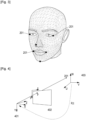
- the figure 2 represents example of this characteristic points 201.
- the figure 3 represents an example of the 3D model of the face with the characteristic points 201 located.
- One may acquire values of parameters of the camera parameters. These values may be expressed as the following 3x3 matrix which may be used during a determination of a pose of the head: camera matrix f x 0 c x 0 f y c y 0 0 1 f x and f y are values of the focal length of the camera while c x and c y are values of the optical centre of the camera. While the camera parameters may be unique to a specific camera, one may estimate these parameters from the image (the image presented on the image plane). Both f x and f y may be directly proportional to the width of the image while the coordinates at mid-width and mid-height of the image can be assumed to be the optical centre of the camera.
- 401 is the world coordinates, with coordinates being U, V and W.
- 402 is the image plane coordinates, with coordinates being x and y.
- 403 is the camera coordinates, with coordinates being X, Y et Z.
- the image plane coordinates 402 may be the screen of the hand-held device 102.
- the coordinates in world coordinates 401 of the characterising points 201 of the face may be determined based on the coordinates in camera coordinates 403 using a transformation comprising for example a rotation R and a translation t.
- the characterising points 201 in camera coordinates 403 may be projected in the image plane coordinates 402 using the intrinsic parameters of the camera (focal length, optical centre etc.).
- This distance may be estimated using scale referencing method.
- One may require a distance between the two pupils of the user and the corresponding value of number of pixels in the image.
- Figure 6 represents the distance P' between the two pupils and the distance D' between the eyes of the user and the hand-held device 102.
- the camera of the head-worn device 103 may be used to obtain images of a field of view of the user. These images may be used to determine the use of the hand-held device 102, for example by determining when the hand-held device 102 is within the field of view of the user.
- the method for detecting the use of the hand-held device 102 by the user wearing the head-worn device 103 is represented schematically in the figure 7 .
- the method for detecting the use of the hand-held device 102 by the user wearing the head-worn device 103 comprises:
- relative motion of a first object with respect to a second object one means the motion of the first object in a referentiel in which the second object is fixed.
- the relative motion may be determined based on an absolute motion of the hand-held device 102 and an absolute motion of the head-worn device 103.
- the absolute motion of the hand-held device 102 may be obtained from the motion determination module of the hand-held device 102.
- the parameter may be an amplitude of the relative motion or a variation of the relative motion, for example a first-order or second-order derivation of the amplitude of the relative motion.
- the method of the figure 2 may also comprise, when detecting that the user is using the hand-held device 102, a step 801 of adapting, toward an optimal value, a value of a parameter of a function of an element of the hand-held device 102.
- the optimal value may be a value of the parameter of the function of the element of the hand-held device 102 that make using the hand-held device 102 the most comfortable for the user.
- the hand-held device 102 may be configured to display the elements of the screen of the hand-held device 102 so that the user is holding the hand-held device 102 at the Harmon distance.
- the Harmon distance is the most comfortable distance for close work.
- the Harmon distance depends on the distance between the tip of the elbow and the middle of the index finger.
- the method of the figure 7 or the figure 8 may also comprises, when detecting that the user is using the hand-held device 102, a step of adapting, toward an optimal value, a value of a parameter of a function of an element of the head-worn device 103.
- the optimal value may be a value of the parameter of the function of the element of the head-worn device 103 that make using the hand-held device 102 the most comfortable for the user.
- the element of the head-worn device 103 may be an optical device or an active optical device.
- the function may be chosen among the functionalities described above.
- the adaptation of the value toward the optimal value is increased when the predetermined threshold is decreased.
- the optimal value of the function of the element of the head-worn device 103 or the optimal value of the function of the element of the head-worn device 103 may depend on values of environmental parameters and/or values of physiological parameters of the user.
- the environmental parameters may comprise:
- the physiological parameters of the user may comprise:
- the figure 9 represents another embodiment of the method of the figure 7 .
- the step 701 of determining the relative motion and the step 702 of detecting, based on the relative motion, the use of the hand-held device 102 may form a first test 901.
- the method of this disclosure may also comprise a step 902 of detecting, using a second test, the use of the hand-held device 102 by the user.
- the method of this disclosure may also comprise, when detecting, using the second test 902, that the user is using the hand-held device 102, a step 903 of realising a second adaptation, toward the optimal value, of the value of the parameter of the function of the element of the hand-held device 102.
- the first adaptation may depend on a value of a parameter of the first test 901 and/or the second adaptation may depend on a value of a parameter of the second test 902.
- the first test 901 and the second test 902 may be realized by an increasing order of a confidence level of the first test 901 and a confidence level of the second test 902.
- the confidence level of the first test 901 when the confidence level of the first test 901 is higher than the confidence level of the second test 902, one may adapt more, toward the optimal value, the value of the function of the element of the hand-held device 102, during the first adaptation than during the second adaptation.
- the confidence level of the first test 901 is lower than the confidence level of the second test 902, one may adapt more, toward the optimal value, the value of the function of the element of the hand-held device 102, during the second adaptation than during the first adaptation.
- the value of the function of the element of the head-worn device 103 is adapted, during the second adaptation, in addition or instead of the value of the function of the element of the hand-held device 102.
- the confidence level of the first test 901 when the confidence level of the first test 901 is higher than the confidence level of the second test 902, one may adapt more, toward the optimal value, the value of the function of the element of the head-worn device 103, during the first adaptation than during the second adaptation.
- the confidence level of the first test 901 is lower than the confidence level of the second test 902, one may adapt more, toward the optimal value, the value of the function of the element of the head-worn device 103, during the second adaptation than during the first adaptation.
- the second test 902 may comprise a detection of the gaze axis of the user, when the detected gaze axis is crossing the hand-held device 102, the use of the hand-held device 102 is detected.
- the detection of the gaze axis of the user may be realized using the eye tracking module of the hand-held device 102 or using the eye tracking module of the head-worn device 103.
- the second test 902 may comprise a determination of a distance between the head-worn device 103 and the hand-held device 102. When the distance is below a distance threshold, the use of the hand-held device 102 is detected.
- the second test 902 may comprise a detection of a reception by the hand-held device 102 of a notification, when the hand-held device 102 receives the notification, the use of the hand-held device is detected.
- the second test 902 may comprise determining whether a screen of the hand-held device 102 is turned on, when the screen of the hand-held device 102 is determined to be turned on, the use of the hand-held device is detected.
- the second test 902 may comprise obtaining signals from sensors of the hand-held device 102 and the head-worn device 103 and inputting these signals in a machine learning module to determine whether or not the user is using the hand-held device 102.
- the machine learning module may have been previously trained with model signals associating respectively with an indication of whether or not the user is using the hand-held device 102.
- the second test 902 may comprise obtaining signals form the IMU of the hand-held device 102 or the IMU of the head-worn device 103, determining an angle of a head of the user, for example using the camera of the head-worn device 103 or the hand-held device 102 and a distance between the hand-held device 102 and the head-worn device 103 or the face of the user. Based on the signals, the angle and the distance one may detect the use of the hand-held device 102 by the user.
- a third test, a fourth test and so on, associated with a third adaptation and a fourth adaptation may be realized.
- the head-worn device 102 may be smart eyeglasses having at least one sensor to measure the motion of the head of the user, active lenses for example electrochromic optical lenses or active lenses on which the power of the lenses can be adapted, a camera and an inertial module unit.
- the hand-held device intended to be used by the user may be a smartphone. This smartphone may comprise a camera and an inertial module unit.
- the images obtained by the camera of the smartphone may be used to detect the use of the smartphone by the user.
- the images obtained by the camera of the smart eyeglasses may be used to detect the use of the smartphone by the user.
- an estimation of the field of view of the user may be realized based on these images and a determination whether or not the smartphone is within this field of view.
- a motion of the head of the user may be detected using the IMU of the smartphone and/or the IMU of the smart eyeglasses.
- signals coming from the IMU of the smartphone and/or the IMU of the smart eyeglasses may be inputted in a machine learning model.
- a reception of a notification by the smartphone is detected and in such case one may consider that the user is using the smartphone.
- the use of the smartphone is detected one may obtain values of environmental parameters (an indication of an activation of the Wi-Fi, an indication of whether the user is indoor or outdoor, a localization of the user, a distance between eyes of the user and smartphone, a type of the smartphone, a type of the usage of the smartphone by the user).
- environmental parameters an indication of an activation of the Wi-Fi, an indication of whether the user is indoor or outdoor, a localization of the user, a distance between eyes of the user and smartphone, a type of the smartphone, a type of the usage of the smartphone by the user.
Landscapes
- Engineering & Computer Science (AREA)
- Theoretical Computer Science (AREA)
- General Engineering & Computer Science (AREA)
- Human Computer Interaction (AREA)
- Physics & Mathematics (AREA)
- General Physics & Mathematics (AREA)
- Computer Hardware Design (AREA)
- User Interface Of Digital Computer (AREA)
- Eye Examination Apparatus (AREA)
Abstract
System and computer-implemented method for detecting a use of a hand-held device by a user wearing a head-worn device, the system comprises a head-worn device and a hand-held device, the system is configured to detect a use of the hand-held device by a user wearing the head-worn device. The system is also configured to determine a relative motion of one among the head-worn device and the hand-held device with respect to another among the head-worn device and the hand-held device and to detect, based on the relative motion, the use of the hand-held device by the user.
Description
- This disclosure relates to systems comprising a head-worn device and a hand-held device and configured to detect a use of the hand-held device by a user wearing the head-worn device. This disclosure also relates to computer-implemented methods configured for the same.
- Detecting the use of the hand-held device by the user wearing the head-worn device may be useful to realize a plurality of actions, for example, to adapt values of parameters of functions of the hand-held device and/or the head-worn device.
- Some systems of the state of the art may realize this detection based on image sensors. However, these systems have several drawbacks. For example, they have the drawback of having weak performance in low light situations.
- The system, according to this disclosure, allows the detection of the use of the hand-held device and avoids the drawbacks previously described.
- The following presents a simplified summary to provide a basic understanding of various aspects of this disclosure. This summary is not an extensive overview of all contemplated aspects and is intended to neither identify key or critical elements of all aspects nor delineate the scope of any or all aspects. The sole purpose is to present some concepts of one or more aspects in a simplified form as a prelude to the more detailed description that is presented later.
- One aspect of this disclosure is a system. The system comprises a head-worn device and a hand-held device. The system is configured to detect a use of the hand-held device by a user wearing the head-worn device. The system is also configured to determine a relative motion of one among the head-worn device and the hand-held device with respect to another among the head-worn device and the hand-held device and, to detect, based on the relative motion, the use of the hand-held device by the user.
- The system of this disclosure is to allow a quicker determination of the use of the hand-held device by the user. Thanks to this quicker determination values of parameters of a function of the hand-held device or the head-worn device may be adapted quicker and therefore the user could use comfortably the hand-held device quicker.
- Another aspect of this disclosure is a computer-implemented method for detecting a use of a hand-held device by a user wearing a head-worn device. The computer-implemented method comprises determining a relative motion of one among the head-worn device and the hand-held device with respect to another among the head-worn device and the hand-held device and detecting, based on the relative motion, the use of the hand-held device by the user.
- A computer may include a memory and a processor. Examples of processors include microprocessors, microcontrollers, graphics processing units (GPUs), central processing units (CPUs), application processors, digital signal processors (DSPs), reduced instruction set computing (RISC) processors, systems on a chip (SoC), field-programmable gate arrays (FPGAs), programmable logic devices (PLDs), state machines, gated logic, discrete hardware circuits, and other suitable hardware configured to perform the various functionality described throughout this disclosure. The memory may be a computer-readable media. By way of example, and not limitation, such computer-readable media may include a random-access memory (RAM), a read-only memory (ROM), an electrically erasable programmable ROM (EEPROM), optical disk storage, magnetic disk storage, other magnetic storage devices, combinations of the aforementioned types of computer-readable media, or any other medium that may be used to store computer executable code in the form of instructions or data structures that may be accessed by the processor of the computer.
- Another aspect of this disclosure is a non-transitory program storage device, readable by a computer, tangibly embodying a program of instructions executable by the computer to perform the computer-implemented for detecting the use of a hand-held device by a user wearing a head-worn device. The computer-implemented method comprises determining a relative motion of one among the head-worn device and the hand-held device with respect to another among the head-worn device and the hand-held device and detecting, based on the relative motion, the use of the hand-held device by the user.
- For a more complete understanding of the description provided herein and the advantages thereof, reference is now made to the brief descriptions below, taken in connection with the accompanying drawings and detailed description, wherein like reference numerals represent like parts.
-
Figure 1 represents a system comprising a hand-held device and a head-worn device. - The
figure 2 represents an example of characteristic points of a face of the user. - The
figure 3 represents an example of a 3D model of the face. - The
figure 4 represents 3 coordinate systems. - The
figure 5 represents characteristic points of the iris. - The
figure 6 represents the distance between the two pupils and the distance between the eyes of the user and the hand-held device. -
Figure 7 represents a first example of a method for detecting the use of the hand-held device by the user wearing the head-worn device. -
Figure 8 represents a second example of a method for detecting the use of the hand-held device by the user wearing the head-worn device. -
Figure 9 represents a second example of a method for detecting the use of the hand-held device by the user wearing the head-worn device. - The detailed description set forth below in connection with the appended drawings is intended as a description of various possible embodiments and is not intended to represent the only embodiments in which the concepts described herein may be practiced. The detailed description includes specific details for the purpose of providing a thorough understanding of various concepts. However, it will be apparent to those skilled in the art that these concepts may be practiced without these specific details. In some instances, well-known structures and components are shown in block diagram form to avoid obscuring such concepts.
-
Figure 1 represent thesystem 101 comprising a hand-helddevice 102 and a head-worn device 103. - The
system 101 may comprise a detection module configured to detect a use of the hand-helddevice 102 by a user wearing the head-worn device 103. - The detection module may comprise at least one processor and at least one memory. The at least one processor and the at least on memory may be configured to realize the method for detecting a use of the hand-held
device 102 by a user wearing the head-worn device 103. - The detection module may be integrated in the hand-held
device 102 or the head-worn device 103. - Examples of processors include microprocessors, microcontrollers, graphics processing units (GPUs), central processing units (CPUs), application processors, digital signal processors (DSPs), reduced instruction set computing (RISC) processors, systems on a chip (SoC), baseband processors, field-programmable gate arrays (FPGAs), programmable logic devices (PLDs), state machines, gated logic, discrete hardware circuits, and other suitable hardware configured to perform the various functionality described throughout this disclosure.
- The memory may be a computer-readable media. By way of example, and not limitation, such computer-readable media may include a random-access memory (RAM), a read-only memory (ROM), an electrically erasable programmable ROM (EEPROM), optical disk storage, magnetic disk storage, other magnetic storage devices, combinations of the aforementioned types of computer-readable media, or any other medium that may be used to store computer executable code in the form of instructions or data structures that may be accessed by the processor of the calculation module.
- When the detection module is integrated in the hand-held
device 102, the detection module may be integrated in a system on chip (SoC) of the hand-helddevice 102. This system on chip may be also configured to realize other functions of the hand-helddevice 102. - When the detection module is integrated in the head-
worn device 103, the detection module may be integrated in a system on chip (SoC) of the head-worn device 103. This system on chip may be also configured to realize other functions of the head-worn device 103. - The hand-held
device 102 may be an electronic device, for example, a device comprising an electronic display. The electronic device may be a smartphone, a computer or a tablet. - The head-
worn device 103 may be eyeglasses, for example smart eyeglasses or a clip configured to be attachable to eyeglasses. - The head-
worn device 103 may also comprise an optical device. This optical device may be an active optical device. - The active optical device may be an electrochromic optical lens or may be configured to display elements. To display elements, the active optical elements may comprise a Light Optical Element (LOE).
- By an active optical device, one means an optical device in which a value of a parameter of a functionality of the optical device can be modified on-demand. The value of the parameter may be modified by applying a signal, for example an electrical signal to terminals of the active optical device. The functionality may be one of the following:
- a transmittance level of the active optical device,
- a tint of the active optical device,
- a reflectance level of the active optical device and
- a parameter of a polarization of the active optical device, for example a polarization angle of the active optical device,
- an optical power of the active optical device,
- elements displayed by the active optical device. The elements may be images, symbols, letters, or texts. In embodiments, the elements to be displayed and the position of these elements may be selected.
- The hand-held
device 102 may comprise a motion determination module. - The head-worn
device 103 may comprise a motion determination module. - The motion determination module of the hand-held
device 102 may be an Inertial Measurement Unit (IMU). - The motion determination module of the head-worn
device 103 may be an Inertial Measurement Unit (IMU). - The hand-held
device 102 may comprise an eye tracking module. - The head-worn
device 103 may comprise an eye tracking module. - The hand-held
device 102 may comprise a distance module. - The head-worn
device 103 may comprise a distance module. - The eye tracking module and the distance module of the hand-held
device 102 or of the head-worndevice 103 may be a TrueDepth sensor. - The distance module may be configured for determining a distance between the hand-held
device 102 and the head-worndevice 103 or the eye of the user. - The
system 101 of this disclosure allows a detection of the use of the hand-helddevice 102 by the user. Once the use is detected thesystem 101 may be configured to adapt a value of a parameter of a function of the hand-helddevice 102 or the head-worndevice 103. The aim of this adaptation is to allow a better use of the hand-helddevice 102. - The adaptation of the values and the quickness of the detection of the use of the hand-held
device 102 allows a more comfortable use of the hand-helddevice 102. - The hand-held
device 102 and/or the head-worndevice 103 may comprise a camera. - The camera of the hand-held
device 102 may be used to obtain images of a face of the user. These images may be used to determine the use of the hand-helddevice 102, for example by determining a gaze axis of the user. - The images of the face of the user may be treated frame by frame independently. The images may be treated in real time. The camera of the hand-held
device 102 may be activated in background while the hand-helddevice 102 is held by the user. - To determine an angle of a head of the user, one may extract location, on the images acquired by the camera, of characteristic points of the face of the user. These characteristic points may be chosen among:
- the left eye corner of the left eye or of the right eye,
- the right eye corner of the left eye or of the right eye,
- the nose tip,
- the left lip corner,
- the right lip corner and
- the chin.
- The
figure 2 represents example of this characteristic points 201. - Using the
characteristic points 201 of thefigure 2 one may determine a 3D model of the face of the user. Thefigure 3 represents an example of the 3D model of the face with thecharacteristic points 201 located. - One may acquire values of parameters of the camera parameters. These values may be expressed as the following 3x3 matrix which may be used during a determination of a pose of the head:

fx and fy are values of the focal length of the camera while cx and cy are values of the optical centre of the camera. While the camera parameters may be unique to a specific camera, one may estimate these parameters from the image (the image presented on the image plane). Both fx and fy may be directly proportional to the width of the image while the coordinates at mid-width and mid-height of the image can be assumed to be the optical centre of the camera. - After getting the necessary parameters, one may determine the angles of the head. There are three coordinate systems usable to determine these angles. These coordinate systems are represented
figure 4 . 401 is the world coordinates, with coordinates being U, V and W. 402 is the image plane coordinates, with coordinates being x and y. 403 is the camera coordinates, with coordinates being X, Y et Z. The image plane coordinates 402 may be the screen of the hand-helddevice 102. The coordinates in world coordinates 401 of the characterising points 201 of the face may be determined based on the coordinates in camera coordinates 403 using a transformation comprising for example a rotation R and a translation t. The characterising points 201 in camera coordinates 403 may be projected in the image plane coordinates 402 using the intrinsic parameters of the camera (focal length, optical centre etc.). - The relationship between the image coordinates and the camera coordinates based on intrinsic parameters of the camera may be model using the equation below:

- Here, the camera coordinates may be transformed into world coordinates by a translation and rotation transformation (i.e., the head angles and translation)

- The images obtained from the camera of the hand-held
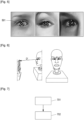
device 102 may also be used to determine a motion of an iris of the user. The skilled person would know how to realise this determination, for example the skilled person would know to use an iris tracking model to obtain landmarks of the iris. The skilled person may use the mediapipe library of the company Google. One may determine 5 characteristic points of the iris (4 on the circumference of the iris and 1 in the centre of the iris). The coordinates of the centre of the iris are extracted to track the motion of the iris from frame to frame.Figure 5 representscharacteristic points 501 of the iris. - Using the images obtained from the camera of the hand-held
device 102 one may also determine the distance between the hand-helddevice 102 and the eyes of the user. - This distance may be estimated using scale referencing method. One may require a distance between the two pupils of the user and the corresponding value of number of pixels in the image.
Figure 6 represents the distance P' between the two pupils and the distance D' between the eyes of the user and the hand-helddevice 102. The distance D' may be obtained using the following formula:
- The camera of the head-worn
device 103 may be used to obtain images of a field of view of the user. These images may be used to determine the use of the hand-helddevice 102, for example by determining when the hand-helddevice 102 is within the field of view of the user. - The method for detecting the use of the hand-held
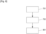
device 102 by the user wearing the head-worndevice 103 is represented schematically in thefigure 7 . The method for detecting the use of the hand-helddevice 102 by the user wearing the head-worndevice 103 comprises: - a
step 701 of determining a relative motion of one among the head-worndevice 103 and the hand-helddevice 102 with respect to another among the head-worndevice 103 and the hand-helddevice 102, - a
step 702 of detecting, based on the relative motion, the use of the hand-helddevice 102 by the user. - By relative motion of a first object with respect to a second object, one means the motion of the first object in a referentiel in which the second object is fixed.
- The relative motion may be determined based on an absolute motion of the hand-held
device 102 and an absolute motion of the head-worndevice 103. - The absolute motion of the hand-held
device 102 may be obtained from the motion determination module of the hand-helddevice 102. - The absolute motion of the head-worn
device 103 may be obtained from the motion determination module of the head-worndevice 103. - In embodiments, the
step 702 of detecting the use of the hand-helddevice 102 by the user may comprise: - determining a value of a parameter of the relative motion,
- determining when the user is using the hand-held device by comparing the value with a predetermined threshold.
- The parameter of the relative motion may be a speed of the relative motion, for example expressed in °/s. According to tests realized by the applicant, the predetermined threshold may be chosen between 10°/s and 6°/s.
- The parameter may be an amplitude of the relative motion or a variation of the relative motion, for example a first-order or second-order derivation of the amplitude of the relative motion.
- One may compare the value with the predetermined threshold and, when the value is below the predetermined threshold, considers that the user is using the electronic device.
- As presented in
figure 3 , in embodiments, the method of thefigure 2 may also comprise, when detecting that the user is using the hand-helddevice 102, astep 801 of adapting, toward an optimal value, a value of a parameter of a function of an element of the hand-helddevice 102. - The optimal value may be a value of the parameter of the function of the element of the hand-held
device 102 that make using the hand-helddevice 102 the most comfortable for the user. For example the hand-helddevice 102 may be configured to display the elements of the screen of the hand-helddevice 102 so that the user is holding the hand-helddevice 102 at the Harmon distance. The Harmon distance is the most comfortable distance for close work. The Harmon distance depends on the distance between the tip of the elbow and the middle of the index finger. - The more a confidence of the detection, that the user is using the hand-held
device 102, is high, the more the value of the parameter of the function of the element of the hand-helddevice 102 is adapted toward the optimal value. - For example, if the test of the previous section is used, the adaptation of the value toward the optimal value is increased when the predetermined threshold is decreased.
- In embodiments the method of the
figure 7 or thefigure 8 may also comprises, when detecting that the user is using the hand-helddevice 102, a step of adapting, toward an optimal value, a value of a parameter of a function of an element of the head-worndevice 103. - As previously the optimal value may be a value of the parameter of the function of the element of the head-worn
device 103 that make using the hand-helddevice 102 the most comfortable for the user. - The element of the head-worn
device 103 may be an optical device or an active optical device. When the element is an active optical device, the function may be chosen among the functionalities described above. - The more a confidence of the detection, that the user is using the hand-held device102 , is high, the more the value of the parameter of the function of the element of the head-worn
device 103 is adapted toward the optimal value of the parameter of the function of the element of the head-worndevice 103. - For example, if the test of the previous section is used, the adaptation of the value toward the optimal value is increased when the predetermined threshold is decreased.
- The optimal value of the function of the element of the head-worn
device 103 or the optimal value of the function of the element of the head-worndevice 103 may depend on values of environmental parameters and/or values of physiological parameters of the user. - The environmental parameters may comprise:
- an indication of an activation of the Wi-Fi,
- an amount of an ambient light,
- a distance between eyes of the user and the hand-held
device 102, - a type of the hand-held
device 102 - a type of the usage of the hand-held
device 102 by the user (for example reading, scrolling pictures or articles or watching movies) and/or - indoor or outdoor conditions
- The physiological parameters of the user may comprise:
- an age of the user
- a refraction of the user and/or
- parameters representing a visual performance of the user, for example a visual acuity of the user and a dynamic visual acuity of the user.
- The
figure 9 represents another embodiment of the method of thefigure 7 . As presented infigure 9 thestep 701 of determining the relative motion and thestep 702 of detecting, based on the relative motion, the use of the hand-helddevice 102 may form afirst test 901. As presented infigure 9 the method of this disclosure may also comprise astep 902 of detecting, using a second test, the use of the hand-helddevice 102 by the user. As presented in thefigure 9 , the method of this disclosure may also comprise, when detecting, using thesecond test 902, that the user is using the hand-helddevice 102, astep 903 of realising a second adaptation, toward the optimal value, of the value of the parameter of the function of the element of the hand-helddevice 102. - The first adaptation may depend on a value of a parameter of the
first test 901 and/or the second adaptation may depend on a value of a parameter of thesecond test 902. - The
first test 901 and thesecond test 902 may be realized by an increasing order of a confidence level of thefirst test 901 and a confidence level of thesecond test 902. - This classification generally implies that the tests are ordered de facto by increasing order of complexity.
- In embodiments, when the confidence level of the
first test 901 is higher than the confidence level of thesecond test 902, one may adapt more, toward the optimal value, the value of the function of the element of the hand-helddevice 102, during the first adaptation than during the second adaptation. When the confidence level of thefirst test 901 is lower than the confidence level of thesecond test 902, one may adapt more, toward the optimal value, the value of the function of the element of the hand-helddevice 102, during the second adaptation than during the first adaptation. - In embodiments the value of the function of the element of the head-worn
device 103 is adapted, during the second adaptation, in addition or instead of the value of the function of the element of the hand-helddevice 102. - In embodiments, when the confidence level of the
first test 901 is higher than the confidence level of thesecond test 902, one may adapt more, toward the optimal value, the value of the function of the element of the head-worndevice 103, during the first adaptation than during the second adaptation. When the confidence level of thefirst test 901 is lower than the confidence level of thesecond test 902, one may adapt more, toward the optimal value, the value of the function of the element of the head-worndevice 103, during the second adaptation than during the first adaptation. - The
second test 902 may comprise a detection of the gaze axis of the user, when the detected gaze axis is crossing the hand-helddevice 102, the use of the hand-helddevice 102 is detected. - The detection of the gaze axis of the user may be realized using the eye tracking module of the hand-held
device 102 or using the eye tracking module of the head-worndevice 103. - The
second test 902 may comprise a determination of a distance between the head-worndevice 103 and the hand-helddevice 102. When the distance is below a distance threshold, the use of the hand-helddevice 102 is detected. - The
second test 902 may comprise a detection of a reception by the hand-helddevice 102 of a notification, when the hand-helddevice 102 receives the notification, the use of the hand-held device is detected. - The
second test 902 may comprise determining whether a screen of the hand-helddevice 102 is turned on, when the screen of the hand-helddevice 102 is determined to be turned on, the use of the hand-held device is detected. - The
second test 902 may comprise obtaining signals from sensors of the hand-helddevice 102 and the head-worndevice 103 and inputting these signals in a machine learning module to determine whether or not the user is using the hand-helddevice 102. The machine learning module may have been previously trained with model signals associating respectively with an indication of whether or not the user is using the hand-helddevice 102. - The
second test 902 may comprise obtaining signals form the IMU of the hand-helddevice 102 or the IMU of the head-worndevice 103, determining an angle of a head of the user, for example using the camera of the head-worndevice 103 or the hand-helddevice 102 and a distance between the hand-helddevice 102 and the head-worndevice 103 or the face of the user. Based on the signals, the angle and the distance one may detect the use of the hand-helddevice 102 by the user. - In embodiments a third test, a fourth test and so on, associated with a third adaptation and a fourth adaptation may be realized.
- In a use case the head-worn
device 102 may be smart eyeglasses having at least one sensor to measure the motion of the head of the user, active lenses for example electrochromic optical lenses or active lenses on which the power of the lenses can be adapted, a camera and an inertial module unit. The hand-held device intended to be used by the user may be a smartphone. This smartphone may comprise a camera and an inertial module unit. - In a first test the images obtained by the camera of the smartphone may be used to detect the use of the smartphone by the user.
- In a second test the images obtained by the camera of the smart eyeglasses may be used to detect the use of the smartphone by the user. To realize the detection an estimation of the field of view of the user may be realized based on these images and a determination whether or not the smartphone is within this field of view.
- In a third test a motion of the head of the user may be detected using the IMU of the smartphone and/or the IMU of the smart eyeglasses. For example, signals coming from the IMU of the smartphone and/or the IMU of the smart eyeglasses may be inputted in a machine learning model.
- In a fourth test a reception of a notification by the smartphone is detected and in such case one may consider that the user is using the smartphone.
- Once, based on the above presented four tests, the use of the smartphone is detected one may obtain values of environmental parameters (an indication of an activation of the Wi-Fi, an indication of whether the user is indoor or outdoor, a localization of the user, a distance between eyes of the user and smartphone, a type of the smartphone, a type of the usage of the smartphone by the user).
- Based on the values of these environmental parameters and possibly of the values of the physiological parameters, for example and advantageously the refraction of the user, once the use of the smartphone is detected, one may adapt a value of the function of the active lens.
Claims (15)
- System (101) comprising a head-worn device (103) and a hand-held device (102), the system (101) being configured to detect a use of the hand-held device (102) by a user wearing the head-worn device (103),
the system (101) being also configured:- to determine a relative motion of one among the head-worn device (103) and the hand-held device (102) with respect to another among the head-worn device (103) and the hand-held device (102) and,- to detect, based on the relative motion, the use of the hand-held device (102) by the user. - The system (101) according to the claim 1,the head-worn device (103) comprising a motion determination module and/orthe hand-held device (102) comprising a motion determination module.
- The system (101) according to the claim 1 or 2,
the system (101) being also configured:- to determine a value of a parameter of the relative motion,- to determine when the user is using the hand-held device (102) by comparing the value with a predetermined threshold. - The system (101) according to any one of the claims 1 to 3,
the system (101) being also configured:- when detecting that the user is using the hand-held device (102), to adapt, toward an optimal value, a value of a parameter of a function of an element of the head-worn device (103). - The system (101) according to the claim 4, the optimal value depending on values of environmental parameters and/or values of physiological parameters of the user.
- The system (101) according to the claim 4 or 5,the determination of the relative motion and the detection, based on the relative motion, of the use of the hand-held device (102) by the user, are together a first test (901),the adaptation is a first adaptation,the system (101) being configured:- to detect, using a second test (902), the use of the hand-held device (102) by the user,- when detecting, using the second test (902), that the user is using the hand-held device (102), to realise a second adaptation, toward the optimal value, of the value of the parameter of the function of the element of the head-worn device (103).
- The system (101) according to the claim 6,the first adaptation depending on a value of a parameter of the first test (901) and/orthe second adaptation depending on a value of a parameter of the second test (902).
- The system (101) according to the claim 6 or 7,
the system being configured to realize the first test (901) and the second test (902) by an increasing order of a confidence level of the first test (901) and a confidence level of the second test (902). - The system (101) according to the claim 8,
the system (101) being configured:- when the confidence level of the first test (901) is higher than the confidence level of the second test (902), to adapt more, toward the optimal value, the value of the function of the element of the head-worn device (103), during the first adaptation than during the second adaptation and/or- when the confidence level of the first test (901) is lower than the confidence level of the second test (902), to adapt more, toward the optimal value, the value of the function of the element of the head-worn device (103), during the second adaptation than during the first adaptation. - The system (101) according to anyone of the claims 6 to 9,
the second test (902) comprising a detection of a gaze axis of the user, when the detected gaze axis is crossing the hand-held device, the use of the hand-held device (102) is detected. - The system (101) according to anyone of the claims 6 to 9,the second test (902) comprising a detection of a reception by the hand-held device (102) of a notification, when the hand-held device (102) receives the notification, the use of the hand-held device (102) is detected and/orthe second test (902) comprising determining whether a screen of the hand-held device (102) is turned on, when the screen of the hand-held device (102) is determined to be turned on, the use of the hand-held device (102) is detected.
- The system (101) according to any one of the claims 4 to 11,the optimal value being a first optimal value,the system (101) being also configured:- when detecting that the user is using the hand-held device (102), to adapt, toward a second optimal value, a value of a parameter of a function of an element of the hand-held device (102).
- The system (101) according to any one of the claims 1 to 12,
the head-worn device (103) being eyeglasses or a clip configured to be attachable to eyeglasses. - The system (101) according to any one of the claims 1 to 13,
the hand-held device (102) being a smartphone. - Computer-implemented method for detecting a use of a hand-held device by a user wearing a head-worn device,
the computer-implemented method comprising:- determining (701) a relative motion of one among the head-worn device and the hand-held device with respect to another among the head-worn device and the hand-held device,- detecting (702), based on the relative motion, the use of the hand-held device by the user.
Priority Applications (3)
| Application Number | Priority Date | Filing Date | Title |
|---|---|---|---|
| EP23306802.2A EP4542342A1 (en) | 2023-10-16 | 2023-10-16 | System comprising a head-worn device and a hand-held device and configured to detect a use of the hand-held device by a user wearing the head-worn device |
| US18/909,056 US20250123682A1 (en) | 2023-10-16 | 2024-10-08 | System comprising a head-worn device and a hand-held device and configured to detect a use of the hand-held device by a user wearing the head-worn device |
| CN202411426906.XA CN119847347A (en) | 2023-10-16 | 2024-10-14 | System comprising a head-mounted device and a handheld device and configured to detect use of the handheld device by a user wearing the head-mounted device |
Applications Claiming Priority (1)
| Application Number | Priority Date | Filing Date | Title |
|---|---|---|---|
| EP23306802.2A EP4542342A1 (en) | 2023-10-16 | 2023-10-16 | System comprising a head-worn device and a hand-held device and configured to detect a use of the hand-held device by a user wearing the head-worn device |
Publications (1)
| Publication Number | Publication Date |
|---|---|
| EP4542342A1 true EP4542342A1 (en) | 2025-04-23 |
Family
ID=88600319
Family Applications (1)
| Application Number | Title | Priority Date | Filing Date |
|---|---|---|---|
| EP23306802.2A Pending EP4542342A1 (en) | 2023-10-16 | 2023-10-16 | System comprising a head-worn device and a hand-held device and configured to detect a use of the hand-held device by a user wearing the head-worn device |
Country Status (3)
| Country | Link |
|---|---|
| US (1) | US20250123682A1 (en) |
| EP (1) | EP4542342A1 (en) |
| CN (1) | CN119847347A (en) |
Citations (2)
| Publication number | Priority date | Publication date | Assignee | Title |
|---|---|---|---|---|
| US20170060266A1 (en) * | 2015-08-31 | 2017-03-02 | Xiaomi Inc. | Screen control method and device |
| US20170163578A1 (en) * | 2015-12-08 | 2017-06-08 | International Business Machines Corporation | System and method for message delivery |
Family Cites Families (11)
| Publication number | Priority date | Publication date | Assignee | Title |
|---|---|---|---|---|
| US9019068B2 (en) * | 2010-04-01 | 2015-04-28 | Apple Inc. | Method, apparatus and system for automated change of an operating mode relating to a wireless device |
| US10231614B2 (en) * | 2014-07-08 | 2019-03-19 | Wesley W. O. Krueger | Systems and methods for using virtual reality, augmented reality, and/or a synthetic 3-dimensional information for the measurement of human ocular performance |
| US20170279957A1 (en) * | 2013-08-23 | 2017-09-28 | Cellepathy Inc. | Transportation-related mobile device context inferences |
| US9406211B2 (en) * | 2014-11-19 | 2016-08-02 | Medical Wearable Solutions Ltd. | Wearable posture regulation system and method to regulate posture |
| JP2019502246A (en) * | 2015-12-05 | 2019-01-24 | ユメ クラウド インコーポレーテッド | Electronic system with presentation mechanism and method of operation thereof |
| US9738125B1 (en) * | 2016-05-17 | 2017-08-22 | Horizon Global Americas Inc. | Communication device, system, and method for active control of external vehicle components |
| EP3543829A1 (en) * | 2018-03-19 | 2019-09-25 | Padrone AG | Method and finger-worn device for controlling an external computer |
| US12346818B2 (en) * | 2019-08-19 | 2025-07-01 | Board Of Trustees Of Michigan State University | Systems and methods for implementing flexible, input-adaptive deep learning neural networks |
| KR102766471B1 (en) * | 2021-05-19 | 2025-02-12 | 스냅 인코포레이티드 | Touchpad input for augmented reality display devices |
| US11755150B2 (en) * | 2021-09-21 | 2023-09-12 | Apple Inc. | Input location correction based on device motion |
| US20240078004A1 (en) * | 2022-09-07 | 2024-03-07 | Meta Platforms Technologies, Llc | Authoring context aware policies with real-time feedforward validation in extended reality |
-
2023
- 2023-10-16 EP EP23306802.2A patent/EP4542342A1/en active Pending
-
2024
- 2024-10-08 US US18/909,056 patent/US20250123682A1/en active Pending
- 2024-10-14 CN CN202411426906.XA patent/CN119847347A/en active Pending
Patent Citations (2)
| Publication number | Priority date | Publication date | Assignee | Title |
|---|---|---|---|---|
| US20170060266A1 (en) * | 2015-08-31 | 2017-03-02 | Xiaomi Inc. | Screen control method and device |
| US20170163578A1 (en) * | 2015-12-08 | 2017-06-08 | International Business Machines Corporation | System and method for message delivery |
Non-Patent Citations (2)
| Title |
|---|
| HO JIMMY R02944004@NTU EDU TW ET AL: "EyeProtector Encouraging a Healthy Viewing Distance when Using Smartphones", HOT TOPICS IN MIDDLEBOXES AND NETWORK FUNCTION VIRTUALIZATION, ACM, 2 PENN PLAZA, SUITE 701 NEW YORK NY 10121-0701 USA, 24 August 2015 (2015-08-24), pages 77 - 85, XP058513576, ISBN: 978-1-4503-3540-9, DOI: 10.1145/2785830.2785836 * |
| LEE JI YEON ALL4ME8911@GMAIL COM ET AL: "EYE DEAR Smartphone Text Resizing Interaction for the Eye Health of the Presbyopia Population", PROCEEDINGS OF THE 35TH IEEE/ACM INTERNATIONAL CONFERENCE ON AUTOMATED SOFTWARE ENGINEERING, ACM, 2 PENN PLAZA, SUITE 701NEW YORKNY10121-0701USA, 20 October 2017 (2017-10-20), pages 161 - 163, XP058936399, ISBN: 978-1-4503-7001-1, DOI: 10.1145/3131785.3131830 * |
Also Published As
| Publication number | Publication date |
|---|---|
| CN119847347A (en) | 2025-04-18 |
| US20250123682A1 (en) | 2025-04-17 |
Similar Documents
| Publication | Publication Date | Title |
|---|---|---|
| US20250131583A1 (en) | Line-of-sight direction tracking method and apparatus | |
| US10413177B2 (en) | Eyeball observation device, eyewear terminal, line-of-sight detection method, and program | |
| US10692210B2 (en) | Recording medium storing computer program for pupil detection, information processing apparatus, and pupil detecting method | |
| US9733703B2 (en) | System and method for on-axis eye gaze tracking | |
| US9291834B2 (en) | System for the measurement of the interpupillary distance using a device equipped with a display and a camera | |
| US20190302878A9 (en) | Virtual reality interaction method, apparatus and system | |
| US8406479B2 (en) | Visual axis direction detection device and visual line direction detection method | |
| CN109690553A (en) | The system and method for executing eye gaze tracking | |
| CN107209849A (en) | Eyes are tracked | |
| US20210165993A1 (en) | Neural network training and line of sight detection methods and apparatus, and electronic device | |
| US10394321B2 (en) | Information acquiring method, information acquiring apparatus, and user equipment | |
| KR20160108388A (en) | Eye gaze detection with multiple light sources and sensors | |
| EP3699808B1 (en) | Facial image detection method and terminal device | |
| Sun et al. | Real-time gaze estimation with online calibration | |
| US12026980B2 (en) | Pupil ellipse-based, real-time iris localization | |
| US9924861B2 (en) | System and methods for assessing vision using a computing device | |
| CN109634431B (en) | Media-free floating projection visual tracking interactive system | |
| CN117935343A (en) | Pupil positioning data processing system, method and device | |
| US10642353B2 (en) | Non-transitory computer-readable storage medium, information processing apparatus, and information processing method | |
| TWI718410B (en) | Method and apparatus for pre-load display of object information | |
| US20250123682A1 (en) | System comprising a head-worn device and a hand-held device and configured to detect a use of the hand-held device by a user wearing the head-worn device | |
| EP3440532B1 (en) | Improving readability of content displayed on a screen | |
| US20240153136A1 (en) | Eye tracking | |
| CN115410242B (en) | Line of sight estimation method and apparatus | |
| Elahi et al. | Webcam-based accurate eye-central localization |
Legal Events
| Date | Code | Title | Description |
|---|---|---|---|
| PUAI | Public reference made under article 153(3) epc to a published international application that has entered the european phase |
Free format text: ORIGINAL CODE: 0009012 |
|
| STAA | Information on the status of an ep patent application or granted ep patent |
Free format text: STATUS: THE APPLICATION HAS BEEN PUBLISHED |
|
| AK | Designated contracting states |
Kind code of ref document: A1 Designated state(s): AL AT BE BG CH CY CZ DE DK EE ES FI FR GB GR HR HU IE IS IT LI LT LU LV MC ME MK MT NL NO PL PT RO RS SE SI SK SM TR |
|
| STAA | Information on the status of an ep patent application or granted ep patent |
Free format text: STATUS: REQUEST FOR EXAMINATION WAS MADE |
|
| 17P | Request for examination filed |
Effective date: 20250926 |