EP4542333A1 - Wearable device - Google Patents
Wearable device Download PDFInfo
- Publication number
- EP4542333A1 EP4542333A1 EP24173192.6A EP24173192A EP4542333A1 EP 4542333 A1 EP4542333 A1 EP 4542333A1 EP 24173192 A EP24173192 A EP 24173192A EP 4542333 A1 EP4542333 A1 EP 4542333A1
- Authority
- EP
- European Patent Office
- Prior art keywords
- pieces
- detachable structure
- detachable
- installing
- inductive
- Prior art date
- Legal status (The legal status is an assumption and is not a legal conclusion. Google has not performed a legal analysis and makes no representation as to the accuracy of the status listed.)
- Pending
Links
Images



Classifications
-
- G—PHYSICS
- G06—COMPUTING OR CALCULATING; COUNTING
- G06F—ELECTRIC DIGITAL DATA PROCESSING
- G06F1/00—Details not covered by groups G06F3/00 - G06F13/00 and G06F21/00
- G06F1/16—Constructional details or arrangements
- G06F1/1613—Constructional details or arrangements for portable computers
- G06F1/163—Wearable computers, e.g. on a belt
-
- G—PHYSICS
- G04—HOROLOGY
- G04G—ELECTRONIC TIME-PIECES
- G04G21/00—Input or output devices integrated in time-pieces
-
- G—PHYSICS
- G06—COMPUTING OR CALCULATING; COUNTING
- G06F—ELECTRIC DIGITAL DATA PROCESSING
- G06F3/00—Input arrangements for transferring data to be processed into a form capable of being handled by the computer; Output arrangements for transferring data from processing unit to output unit, e.g. interface arrangements
- G06F3/01—Input arrangements or combined input and output arrangements for interaction between user and computer
- G06F3/011—Arrangements for interaction with the human body, e.g. for user immersion in virtual reality
-
- G—PHYSICS
- G01—MEASURING; TESTING
- G01D—MEASURING NOT SPECIALLY ADAPTED FOR A SPECIFIC VARIABLE; ARRANGEMENTS FOR MEASURING TWO OR MORE VARIABLES NOT COVERED IN A SINGLE OTHER SUBCLASS; TARIFF METERING APPARATUS; MEASURING OR TESTING NOT OTHERWISE PROVIDED FOR
- G01D5/00—Mechanical means for transferring the output of a sensing member; Means for converting the output of a sensing member to another variable where the form or nature of the sensing member does not constrain the means for converting; Transducers not specially adapted for a specific variable
- G01D5/12—Mechanical means for transferring the output of a sensing member; Means for converting the output of a sensing member to another variable where the form or nature of the sensing member does not constrain the means for converting; Transducers not specially adapted for a specific variable using electric or magnetic means
- G01D5/14—Mechanical means for transferring the output of a sensing member; Means for converting the output of a sensing member to another variable where the form or nature of the sensing member does not constrain the means for converting; Transducers not specially adapted for a specific variable using electric or magnetic means influencing the magnitude of a current or voltage
- G01D5/142—Mechanical means for transferring the output of a sensing member; Means for converting the output of a sensing member to another variable where the form or nature of the sensing member does not constrain the means for converting; Transducers not specially adapted for a specific variable using electric or magnetic means influencing the magnitude of a current or voltage using Hall-effect devices
- G01D5/145—Mechanical means for transferring the output of a sensing member; Means for converting the output of a sensing member to another variable where the form or nature of the sensing member does not constrain the means for converting; Transducers not specially adapted for a specific variable using electric or magnetic means influencing the magnitude of a current or voltage using Hall-effect devices influenced by the relative movement between the Hall device and magnetic fields
-
- G—PHYSICS
- G01—MEASURING; TESTING
- G01R—MEASURING ELECTRIC VARIABLES; MEASURING MAGNETIC VARIABLES
- G01R33/00—Arrangements or instruments for measuring magnetic variables
- G01R33/12—Measuring magnetic properties of articles or specimens of solids or fluids
-
- G—PHYSICS
- G04—HOROLOGY
- G04B—MECHANICALLY-DRIVEN CLOCKS OR WATCHES; MECHANICAL PARTS OF CLOCKS OR WATCHES IN GENERAL; TIME PIECES USING THE POSITION OF THE SUN, MOON OR STARS
- G04B45/00—Time pieces of which the indicating means or cases provoke special effects, e.g. aesthetic effects
- G04B45/0084—Pictures or inscriptions on the case or parts thereof, attaching complete pictures
- G04B45/0092—Changeable parts
-
- G—PHYSICS
- G04—HOROLOGY
- G04B—MECHANICALLY-DRIVEN CLOCKS OR WATCHES; MECHANICAL PARTS OF CLOCKS OR WATCHES IN GENERAL; TIME PIECES USING THE POSITION OF THE SUN, MOON OR STARS
- G04B47/00—Time-pieces combined with other articles which do not interfere with the running or the time-keeping of the time-piece
- G04B47/04—Time-pieces combined with other articles which do not interfere with the running or the time-keeping of the time-piece with attached ornaments or amusement apparatus
- G04B47/046—Changeable decorations and parts thereof, decorations for the case which change the external appearance of the clockwork
-
- G—PHYSICS
- G04—HOROLOGY
- G04B—MECHANICALLY-DRIVEN CLOCKS OR WATCHES; MECHANICAL PARTS OF CLOCKS OR WATCHES IN GENERAL; TIME PIECES USING THE POSITION OF THE SUN, MOON OR STARS
- G04B19/00—Indicating the time by visual means
- G04B19/28—Adjustable guide marks or pointers for indicating determined points of time
- G04B19/283—Adjustable guide marks or pointers for indicating determined points of time on rotatable rings, i.e. bezel
Definitions
- the disclosure relates to the technical field of electronic devices, in particular to a wearable device.
- a body of a wearable device generally includes a fixed structure and a detachable structure.
- a display of the wearable device typically remains unchanged, which is not conducive to the coordination between the detachable structure and the display of the wearable device.
- the disclosure provides a wearable device.
- a wearable device including: a fixed structure; a processor, where the processor is installed on the fixed structure; and a detachable structure.
- the detachable structure is installed on the fixed structure in a detachable mode, at least one group of inductive pieces are arranged on the detachable structure, each group of inductive pieces includes at least one inductive element, and at least one sensor is arranged on the fixed structure.
- the sensor is configured to detect the inductive element at a corresponding position, different types of at least one group of inductive pieces are arranged on different types of detachable structures, and the processor is in communication connection with the sensor so as to adjust a display of the wearable device according to a detection result of the sensor.
- the inductive element is structured as a magnetic piece
- the sensor is structured as a Hall device.
- At least two groups of inductive pieces are arranged on the detachable structure, the at least two groups of inductive pieces are arranged at intervals in a circumferential direction of the detachable structure, and any two groups of inductive pieces are arranged in a rotationally symmetric mode, where in the any two groups of inductive pieces, poles of two corresponding magnetic pieces arranged in a rotationally symmetric mode are the same.
- the detachable structure has an installing structure configured to install each group of inductive pieces, and the installing structure includes at least two installing grooves used to install the magnetic pieces, where a quantity of the Hall devices equals a quantity of the installing grooves in the installing structure, and a quantity of the magnetic pieces of each group of inductive pieces is smaller than a quantity of the installing grooves in the installing structure.
- the detachable structure has an installing structure configured to install each group of inductive pieces, and the installing structure includes at least two installing grooves used to install the magnetic pieces, where a quantity of the Hall devices equals a quantity of the installing grooves in the installing structure, and a quantity of the magnetic pieces of each group of inductive pieces equals a quantity of the installing grooves in the installing structure.
- the fixed structure has an annular matching part, and the detachable structure is rotatably sleeved in the annular matching part.
- a first turnbuckle is arranged on the annular matching part, a second turnbuckle is arranged on the detachable structure, and the first turnbuckle and the second turnbuckle are clamped together in a rotatably fastening mode.
- the fixed structure has an annular matching part
- the detachable structure is rotatably sleeved in the annular matching part.
- a flexible piece is arranged on one of the annular matching part and the detachable structure, and the flexible piece abuts against the other of the annular matching part and the detachable structure.
- the flexible piece is arranged on the detachable structure, the flexible piece has a first wall surface, and the first wall surface is used to abut against the fixed structure in an axial direction.
- the flexible piece is arranged on the detachable structure, the flexible piece has a second wall surface, and the second wall surface is used to abut against the annular matching part in a radial direction.
- the fixed structure has an annular matching part
- the detachable structure is rotatably sleeved in the annular matching part.
- An elastic sheet is arranged on the detachable structure, the elastic sheet has a first protrusion that protrudes inwardly, the annular matching part is provided with a second protrusion that protrudes outwardly, and when the detachable structure rotates, the first protrusion selectively abuts against the second protrusion.
- the wearable device includes the fixed structure and the detachable structure and the detachable structure can be installed on the fixed structure in a detachable mode, the wearable device can realize that different types of detachable structures are replaced on the same fixed structure, thus achieving detaching of the detachable structure.
- the inductive element is arranged on the detachable structure
- the sensor is arranged on the fixed structure, and the sensor can detect the inductive element at the corresponding position
- the processor adjusts a display of the wearable device according to a detection result of the sensor so that the display of the wearable device matches with the current detachable structure.
- different types of at least one group of inductive pieces are arranged on different types of detachable structures, that is, the different types of detachable structures have different types of inductive pieces.
- orientation terms such as “inside and outside” is defined based on a radial direction of a detachable or fixed structure to mean that the direction along the radius of the detachable or fixed structure towards the center of the circle is inside, and the direction along the center of the circle to the radius is outside.
- first and second are used to distinguish one element from another and do not have sequentiality or significance.
- the following description refers to the accompanying drawings in such a way that the same reference numerals in the different drawings indicate the same or similar elements.
- a wearable device 1 is provided. As shown in Fig. 1 , the wearable device 1 includes: a fixed structure 100; a processor10, where the processor 10 is installed on the fixed structure 100; and a detachable structure 200, the detachable structure 200 is installed on the fixed structure 100 in a detachable mode, at least one group of inductive pieces 20 are arranged on the detachable structure 200, each group of inductive pieces 20 includes at least one inductive element 30, and at least one sensor 40 is arranged on the fixed structure 100.
- the sensor 40 is configured to detect the inductive element 30 at a corresponding position, different types of at least one group of inductive pieces 20 are arranged on different types of detachable structure 200, and the processor 10 is in communication connection with the sensor 40 so as to adjust a display of the wearable device 1 according to a detection result of the sensor 40.
- the wearable device 1 because the wearable device 1 includes the fixed structure 100 and the detachable structure 200, and the detachable structure 200 can be installed on the fixed structure 100 in a detachable mode, the wearable device 1 can realize that the different types of detachable structures 200 are replaced on the same fixed structure 100, thus achieving detaching of the detachable structure 200.
- the inductive element 30 is arranged on the detachable structure 200
- the sensor 40 is arranged on the fixed structure 100, and the sensor 40 can detect the inductive element 30 at the corresponding position
- the sensor 40 can detect the inductive element 30 corresponding to the current detachable structure 200
- the processor 10 adjusts a display of the wearable 1 device according to a detection result of the sensor 40 so that the display of the wearable device 1 matches with the current detachable structure 200.
- the different types of at least one group of inductive pieces 20 are arranged on the different types of detachable structures 200, that is, the different types of detachable structures 200 have different types of inductive pieces.
- automatically adjusting the display of the wearable device 1 can further be easily achieved during replacement of the detachable structure 200 and operation is convenient.
- the "different types of detachable structures 200" may refer to detachable structures 200 in different appearances.
- An appearance of the detachable structure 200 at least includes at least one of a color, a shape, a material, etc. of the detachable structure 200.
- the “different types of detachable structures 200” may refer to detachable structures 200 different in at least one of the color, the shape, or the material.
- the “detection result” may be a type of the detachable structure detected by the sensor 40, that is, the sensor 40 may detect the type of the detachable structure through detecting the type of the at least one group of inductive pieces 20.
- the "the display of the wearable device 1" may refer to display information on a touch control display screen in the wearable device 1.
- the processor 10 may further adjust at least one of the display, vibration, and sound of the wearable device 1 according to the detection result.
- the processor 10 may adjust at least one of display information of a dial plate, audio information broadcast by a speaker, or vibration information triggered by a motor according to the detection result, or may adjust a combination of any two of them, or may adjust the display information, audio information broadcast by the speaker and vibration information triggered by the motor at the same time.
- dial plate here may refer to information displayed on a display interface of the wearable device 1.
- the “detachable structure” and the “fixed structure” here refer to the “detachable structure” and the “fixed structure” included in a body of the wearable device 1.
- the “detachable structure” may refer to a watch bezel of the body of the wearable device 1
- the "fixed structure” may refer to a middle frame of the body of the wearable device 1.
- “different types of at least one group of inductive pieces 20 are arranged on different types of detachable structures 200” refers to that, at least one group of inductive pieces 20 may be arranged on the detachable structures 200, and for the same type of detachable structure 200, the inductive elements 30 at the same positions in each group of inductive pieces 20 are the same; and for the different types of detachable structures 200, in each group of inductive pieces 20, the inductive elements 30 at at least one same position are different, or at the same position, there may be a case that an inductive element 30 is arranged in one group while no inductive element 30 is arranged in another group.
- the inductive elements 30 and the sensor 40 may be structured in any suitable mode.
- the inductive elements 30 may be structured as magnetic pieces 300
- the sensor 40 may be structured as a Hall device 400
- the Hall device 400 is configured to detect magnetic pole information of the magnetic piece 300 at the corresponding position.
- the "different types of at least one group of inductive pieces 20" may refer to that the magnetic pole information of the magnetic pieces 300 in different types of at least one group of inductive pieces 20 is different.
- the Hall device 400 may detect the type of the at least one group of inductive pieces 20 through detecting the magnetic pole information of the magnetic pieces 300, thus detecting the type of the detachable structure, and transmit a detection result, i.e.
- the processor 10 adjusts the display of the wearable device 1.
- the detachable structures 200 rotate relative to the fixed structure 100, so the magnetic pieces 300 and the Hall device 400 rotate from deflected positions with a relatively large distance to positions corresponding to each other.
- a magnetic field strength of the magnetic pieces 300 is higher than a threshold value required by the Hall device 400 so that the Hall device 400 can generate a Hall effect.
- the Hall device 400 detects the magnetic pole information of the magnetic pieces 300 at the corresponding position.
- the inductive elements 30 may be structured as structural members
- the sensor 40 may be structured as an image recognition sensor
- the structural members may be protrusions.
- the "different types of at least one group of inductive pieces 20" may refer to a case that the protrusions in the different types of at least one group of inductive pieces 20 are different in shape or quantity.
- the image recognition sensor may detect the type of the at least one group of inductive pieces 20 by detecting the shapes or quantity of the protrusions, thus detecting the type of the detachable structure, and transmit a detection result, i.e. the type of the detachable structure, to the processor 10, and the processor 10 adjusts the display of the wearable device 1.
- the inductive pieces 20 may be structured in any suitable mode.
- at least two groups of inductive pieces 20 may be arranged on the detachable structure 200, the at least two groups of inductive pieces 20 may be arranged at intervals in a circumferential direction of the detachable structure 200, and any two groups of inductive pieces 20 may be arranged in a rotationally symmetric mode.
- poles of two corresponding magnetic pieces 300 arranged in a rotationally symmetric mode may be the same. That is, in the same type of detachable structure 200, the magnetic pole information of the magnetic pieces 300 in each group of inductive pieces 20 is the same.
- the Hall device 400 can detect the magnetic pole information of the corresponding magnetic pieces 300 so as to determine the type of the current detachable structure 200.
- any two groups of inductive pieces 20 may be arranged in a rotationally symmetric mode” may refer to a case that any two groups of inductive pieces 20 are at the same interval angle. In this way, during installation of the detachable structure 200, installation may be completed when the detachable structure 200 is rotated by at most one interval angle relative to the fixed structure 100.
- a rotation degree of the detachable structure 200 during installation may be reduced, and installation is convenient; and on the other hand, compared to the arrangement of merely one group of inductive pieces 20, the above arrangement can prevent the situation that in an installed wearable device 1, the Hall device 400 fails to recognize the type of the current detachable structure 200 because the magnetic pieces 300 and the Hall device 400 are at non-corresponding positions.
- a quantity of the inductive pieces 20 is three groups, "any two groups of inductive pieces 20 may be arranged in a rotationally symmetric mode" may refer to a case that any two groups of inductive pieces 20 are at the same interval angle of 120°.
- installation may be completed when the detachable structure 200 is rotated by at most 120° relative to the fixed structure 100.
- the magnetic pieces 300 in each group of inductive pieces 20 may be structured in any suitable mode.
- the detachable structure 200 may have an installing structure 50 configured to install each group of inductive pieces 20, and the installing structure 50 may include at least two installing grooves 210 used to install the magnetic pieces 300, where a quantity of the Hall devices 400 may equal a quantity of the installing grooves 210 in the installing structure 50, and a quantity of the magnetic pieces 300 of each group of inductive pieces 20 may be smaller than a quantity of the installing grooves 210 in the installing structure 50.
- the quantity of the magnetic pieces 300 of each group of inductive pieces 20 may be smaller than a quantity of the installing grooves 210 in the installing structure 50
- the magnetic pole information of the magnetic pieces 300 includes an N pole and an S pole
- a quantity of the installing grooves 210 in the installing structure 50 is two, there will be four different types of corresponding detachable structures 200 as follows.
- the magnetic piece 300 is installed in the first installing groove 210a, and in a case of completing installation of the detachable structure 200, the N pole of the magnetic piece 300 can be detected by the Hall device 400; and no magnetic piece 300 is installed in the second installing groove 210b.
- the type of the detachable structure 200 is recorded as a first detachable structure, and the corresponding magnetic pole information detected by the Hall device 400 is: N/.
- the magnetic piece 300 is installed in the first installing groove 210a, and in a case of completing installation of the detachable structure 200, the S pole of the magnetic piece 300 can be detected by the Hall device 400; and no magnetic piece 300 is installed in the second installing groove 210b.
- the type of the detachable structure 200 is recorded as a second detachable structure, and the corresponding magnetic pole information detected by the Hall device 400 is: S/. III.
- No magnetic piece 300 is installed in the first installing groove 210a, the magnetic piece 300 is installed in the second installing groove 210b, and in a case of completing installation of the detachable structure 200, the N pole of the magnetic piece 300 can be detected by the Hall device 400.
- the type of the detachable structure 200 is recorded as a third detachable structure, and the corresponding magnetic pole information detected by the Hall device 400 is: /N. IV.
- No magnetic piece 300 is installed in the first installing groove 210a, the magnetic piece 300 is installed in the second installing groove 210b, and in a case of completing installation of the detachable structure 200, the S pole of the magnetic piece 300 can be detected by the Hall device 400.
- the type of the detachable structure 200 is recorded as a fourth detachable structure, and the corresponding magnetic pole information detected by the Hall device 400 is: /S.
- the detachable structure 200 may have the installing structure 50 configured to install each group of inductive pieces 20, and the installing structure 50 may include at least two installing grooves 210 used to install the magnetic pieces 300, where a quantity of the Hall devices 400 may equal a quantity of the installing grooves 210 in the installing structure 50, and a quantity of the magnetic pieces 300 of each group of inductive pieces 20 may equal a quantity of the installing grooves 210 in the installing structure.
- the magnetic piece 300 is installed in each installing groove 210.
- the quantity of the magnetic pieces 300 of each group of inductive pieces 20 may equal a quantity of the installing grooves 210 in the installing structure 50
- the magnetic pole information of the magnetic pieces 300 includes an N pole and an S pole
- a quantity of the installing grooves 210 in the installing structure 50 is two, there will be four different types of corresponding detachable structures 200 as follows.
- the magnetic pieces 300 are installed in both the first installing groove 210a and second installing groove 210b, and in a case of completing installation of the detachable structure 200, the N pole of the magnetic piece 300 in the first installing groove 210a and the N pole of the magnetic piece 300 in the second installing groove 210b can be respectively detected by the corresponding Hall device 400.
- the type of the detachable structure 200 is recorded as a fifth detachable structure, and the corresponding magnetic pole information detected by the Hall device 400 is: NN. II.
- the magnetic pieces 300 are installed in both the first installing groove 210a and second installing groove 210b, and in a case of completing installation of the detachable structure 200, the N pole of the magnetic piece 300 in the first installing groove 210a and the S pole of the magnetic piece 300 in the second installing groove 210b can be respectively detected by the corresponding Hall device 400.
- the type of the detachable structure 200 is recorded as a sixth detachable structure, and the corresponding magnetic pole information detected by the Hall device 400 is: NS. III.
- the magnetic pieces 300 are installed in both the first installing groove 210a and second installing groove 210b, and in a case of completing installation of the detachable structure 200, the S pole of the magnetic piece 300 in the first installing groove 210a and the N pole of the magnetic piece 300 in the second installing groove 210b can be respectively detected by the corresponding Hall device 400.
- the type of the detachable structure 200 is recorded as a seventh detachable structure, and the corresponding magnetic pole information detected by the Hall device 400 is: SN. IV.
- the magnetic pieces 300 are installed in both the first installing groove 210a and second installing groove 210b, and in a case of completing installation of the detachable structure 200, the S pole of the magnetic piece 300 in the first installing groove 210a and the S pole of the magnetic piece 300 in the second installing groove 210b can be respectively detected by the corresponding Hall device 400.
- the type of the detachable structure 200 is recorded as an eighth detachable structure, and the corresponding magnetic pole information detected by the Hall device 400 is: SS.
- installing groups 210 in other suitable quantity may also be arranged in the installing structure 50.
- a quantity of the installing grooves 210 in the installing structure 50 may be three, four, etc., which is not specifically limited in the invention.
- a quantity of the Hall devices 400 may equal a quantity of the installing grooves 210, and a quantity of the magnetic pieces 300 may be smaller than or equal a quantity of the installing grooves 210.
- the detachable structure 200 may be installed on the fixed structure 100 in a detachable mode in any suitable way.
- the fixed structure 100 may have an annular matching part 110, and the detachable structure 200 may be rotatably sleeved in the annular matching part 110.
- a first turnbuckle 510 may be arranged on the annular matching part 110
- a second turnbuckle 520 may be arranged on the detachable structure 200
- the first turnbuckle 510 and the second turnbuckle 520 may be clamped together in a rotatably fastening mode.
- the first turnbuckle 510 may be arranged as one of a fastener or a clamping groove, and the second turnbuckle 520 may be arranged as the other.
- the fastener can also rotate relative to the clamping groove and be clamped in the clamping groove.
- installation of the detachable structure 200 and the fixed structure 100 can be realized through rotation, and operation is convenient; and on the other hand, detachment of the detachable structure 200 from the fixed structure 100 can be prevented, and it is ensured that the detachable structure 200 is firmly installed.
- an L-shaped baffle may be arranged on an outer side wall of the annular matching part 110, the L-shaped baffle may include a first stopping part 511 and a second stopping part 512, and the first stopping part 511, the second stopping part 512 and a frame body of the fixed structure 100 may jointly define a U-shaped clamping groove with an open end.
- the U-shaped clamping groove is arranged in a circumferential direction of the annular matching part 110 so as to be used as the first turnbuckle 510. As shown in Fig.
- blocking chunks may be arranged on an inner side wall of the detachable structure 200, the blocking chunks may be arranged in the circumferential direction of the detachable structure 200 so as to be used as the second turnbuckle 520.
- the blocking chunks that is, the second turnbuckle 520
- the U-shaped clamping groove that is, the first turnbuckle 510
- enter the U-shaped clamping groove that is, the first turnbuckle 510 from the open end of the U-shaped clamping groove (that is, the first turnbuckle 510).
- the first stopping part 511 and the frame body of the fixed structure 100 can jointly restrict the blocking chunks (that is, the second turnbuckle 520) from moving in an axial direction of the detachable structure 200 relative to the U-shaped clamping groove (that is, the first turnbuckle 510), that is, restricting the detachable structure 200 from being detached from the fixed structure 100 along the axial direction of the detachable structure 200.
- the blocking chunks (that is, the second turnbuckle 520) can be restricted from further rotating relative to the U-shaped clamping groove (that is, the first turnbuckle 510), that is, the detachable structure 200 is restricted from further rotating relative to the fixed structure 100, which reminds an operator of completing installation of the detachable structure 200.
- each Hall device 400 can also detect the magnetic pole information of the corresponding magnetic piece 300.
- a quantity of the first turnbuckles 510 and second turnbuckles 520 may be plural, the first turnbuckles 510 and second turnbuckles 520 may be arranged respectively in one-to-one correspondence.
- the plurality of first turnbuckles 510 may be arranged at intervals in the circumferential direction of the annular matching part 110, and the plurality of second turnbuckles 520 may be arranged at intervals in the circumferential direction of the detachable structure 200.
- one circumference of the detachable structure 200 may be firmly installed on the fixed structure 100 through the first turnbuckles 510 and second turnbuckles 520, thus increasing connection stability.
- the first turnbuckles 510 and second turnbuckles 520 may also be structured in other suitable modes, which is not restricted in the invention.
- the fixed structure 100 may have the annular matching part 110
- the detachable structure 200 may be rotatably sleeved in the annular matching part 110
- a flexible piece 600 may be arranged on one of the annular matching part 110 and the detachable structure 200, and the flexible piece 600 may abut against the other of the annular matching part 110 and the detachable structure 200.
- the flexible piece 600 may be arranged between the annular matching part 110 and the detachable structure 200, and offer buffering during relative rotation between the annular matching part 110 and the detachable structure 200, thus preventing hard contact between the annular matching part 110 and the detachable structure 200, and reducing wearing between the annular matching part 110 and the detachable structure 200.
- a first locating groove 220 for installing the flexible piece 600 may be formed on the detachable structure 200, the flexible piece 600 may be partially accommodated in the first locating groove 220 and be bonded in the first locating groove 220 through glue dispensing, so that an installing position of the flexible piece 600 can be conveniently determined in a processing course.
- a quantity of the flexible piece 600 may be plural, and the plurality of flexible pieces 600 are arranged at intervals in the circumferential direction of the detachable structure 200. In this way, an effect of comprehensive protection may be achieved on the circumference of the detachable structure 200.
- the flexible piece 600 may be structured in any suitable mode.
- the flexible piece 600 may be arranged on the detachable structure 200, the flexible piece 600 may have a first wall surface 610, and the first wall surface 610 may be used to abut against the fixed structure 100 in an axial direction. In this way, the first wall surface 610 may prevent hard contact between the annular matching part 110 and the detachable structure 200 in the axial direction.
- the flexible piece 600 may be arranged on the detachable structure 200, the flexible piece 600 may have a second wall surface 620, and the second wall surface 620 may be used to abut against the annular matching part 110 in a radial direction. In this way, the second wall surface 620 can prevent hard contact between the annular matching part 110 and the detachable structure 200 in a radial direction.
- the fixed structure 100 may have the annular matching part 110
- the detachable structure 200 may be rotatably sleeved in the annular matching part 110
- an elastic sheet 700 may be arranged on the detachable structure 200
- the elastic sheet 700 may have a first protrusion 710 that protrudes inwardly
- a second protrusion 111 that protrudes outwardly may be arranged on the annular matching part 110, and when the detachable structure 200 rotates, the first protrusion 710 may selectively abut against the second protrusion 111.
- the elastic sheet 700 in contact with the second protrusion 111, and at the moment the elastic sheet 700 can move outward in the radial direction of the detachable structure 200 under an abutting effect of the second protrusion 111; and when installation of the detachable structure 200 is completed, the elastic sheet 700 can bypass the second protrusion 111, and at the moment, the elastic sheet 700 can move inward in the radial direction of the detachable structure 200 under an elastic effect of the elastic sheet and strike the annular matching part 110 to cause vibration and make a sound, which reminds the operator of completed installation of the detachable structure 200.
- a distance between the elastic sheet 700 and the annular matching part 110 can be enlarged, so a striking degree of the elastic sheet 700 against the annular matching part 110 is also clearer.
- a quantity of the elastic sheet 700 and the second protrusion 111 may be set to be one or plural, and the elastic sheet 700 and the second protrusion 111 are arranged in one-to-one correspondence.
- the plurality of elastic sheets 700 may be distributed at intervals in the circumferential direction of the detachable structure 200. In this way, a reminding effect for the operator caused by the elastic sheets 700 may be further enhanced.
- the first protrusion 710 and the second protrusion 111 may be arranged in an arc shape on both sides, which facilitates the situation that the elastic sheet 700 is in smooth contact with the second protrusion 111 during rotation, and elastic deformation is caused to prevent clamping of the elastic sheet 700.
- a second locating groove 230 for installing the elastic sheet 700 may be arranged on the detachable structure 200, the elastic sheet 700 may be partially accommodated in the second locating groove 230 and be installed in the second locating groove 230 through laser welding or other modes, and in this way, an installing position of the elastic sheet 700 can be conveniently determined in a processing course.
- two second protrusions 111 may also be arranged.
- the elastic sheet 700 can be located between the two second protrusions 111.
- the purpose of reminding the operator through vibration and sounds can be achieved, and on the other hand, over rotation of the detachable structure 200 by the operator can be prevented through restricting the position of the elastic sheet 700 by the two second protrusions 111.
- the operator may rotate the detachable structure 200 to achieve rotatable fastening between the first turnbuckle 510 and the second turnbuckle 520, and a reminding sound made by the elastic sheet 700 and vibration indicate that the detachable structure 200 has been installed in place; and at the moment, it is no longer needed to rotate the detachable structure 200.
- the Hall device 400 can detect the magnetic pole information of the corresponding magnetic piece 300 so as to determine the type of the current detachable structure 200. Then the processor 10 may adjust the display of the wearable device 1 according to a detection result of the Hall device 400. In this way, instant switching of the corresponding display of the wearable device 1 may be realized during replacement of different types of detachable structures.
Landscapes
- Physics & Mathematics (AREA)
- Engineering & Computer Science (AREA)
- General Physics & Mathematics (AREA)
- Theoretical Computer Science (AREA)
- General Engineering & Computer Science (AREA)
- Human Computer Interaction (AREA)
- Computer Hardware Design (AREA)
- Condensed Matter Physics & Semiconductors (AREA)
- Transmission And Conversion Of Sensor Element Output (AREA)
- Arrangements For Transmission Of Measured Signals (AREA)
Abstract
The disclosure relates to a wearable device (1), including: a fixed structure (100); a processor(10), where the processor is installed on the fixed structure; and a detachable structure (200), where the detachable structure is installed on the fixed structure in a detachable mode, at least one group of inductive pieces (20) are arranged on the detachable structure, each group of inductive pieces includes at least one inductive element (30), and at least one sensor (40) is arranged on the fixed structure. The sensor is configured to detect the inductive element at a corresponding position, different types of at least one group of inductive pieces (20) are arranged on different types of detachable structures (200), and the processor (10) is in communication connection with the sensor (40) so as to adjust a display of the wearable device (1) according to a detection result of the sensor (40).
Description
- The disclosure relates to the technical field of electronic devices, in particular to a wearable device.
- With the rapid development of information technology, there is a constant stream of new advancements in wearable devices. Currently, a body of a wearable device generally includes a fixed structure and a detachable structure. When the detachable structure of the wearable device is being replaced, a display of the wearable device typically remains unchanged, which is not conducive to the coordination between the detachable structure and the display of the wearable device.
- In order to solve the existing problem in the related art, the disclosure provides a wearable device..
- According to a first aspect of the present invention, there is provided a wearable device, including: a fixed structure; a processor, where the processor is installed on the fixed structure; and a detachable structure. The detachable structure is installed on the fixed structure in a detachable mode, at least one group of inductive pieces are arranged on the detachable structure, each group of inductive pieces includes at least one inductive element, and at least one sensor is arranged on the fixed structure. The sensor is configured to detect the inductive element at a corresponding position, different types of at least one group of inductive pieces are arranged on different types of detachable structures, and the processor is in communication connection with the sensor so as to adjust a display of the wearable device according to a detection result of the sensor.
- Optionally, the inductive element is structured as a magnetic piece, and the sensor is structured as a Hall device.
- Optionally, at least two groups of inductive pieces are arranged on the detachable structure, the at least two groups of inductive pieces are arranged at intervals in a circumferential direction of the detachable structure, and any two groups of inductive pieces are arranged in a rotationally symmetric mode, where in the any two groups of inductive pieces, poles of two corresponding magnetic pieces arranged in a rotationally symmetric mode are the same.
- Optionally, the detachable structure has an installing structure configured to install each group of inductive pieces, and the installing structure includes at least two installing grooves used to install the magnetic pieces, where a quantity of the Hall devices equals a quantity of the installing grooves in the installing structure, and a quantity of the magnetic pieces of each group of inductive pieces is smaller than a quantity of the installing grooves in the installing structure.
- Optionally, the detachable structure has an installing structure configured to install each group of inductive pieces, and the installing structure includes at least two installing grooves used to install the magnetic pieces, where a quantity of the Hall devices equals a quantity of the installing grooves in the installing structure, and a quantity of the magnetic pieces of each group of inductive pieces equals a quantity of the installing grooves in the installing structure.
- Optionally, the fixed structure has an annular matching part, and the detachable structure is rotatably sleeved in the annular matching part. A first turnbuckle is arranged on the annular matching part, a second turnbuckle is arranged on the detachable structure, and the first turnbuckle and the second turnbuckle are clamped together in a rotatably fastening mode.
- Optionally, the fixed structure has an annular matching part, and the detachable structure is rotatably sleeved in the annular matching part. A flexible piece is arranged on one of the annular matching part and the detachable structure, and the flexible piece abuts against the other of the annular matching part and the detachable structure.
- Optionally, the flexible piece is arranged on the detachable structure, the flexible piece has a first wall surface, and the first wall surface is used to abut against the fixed structure in an axial direction.
- Optionally, the flexible piece is arranged on the detachable structure, the flexible piece has a second wall surface, and the second wall surface is used to abut against the annular matching part in a radial direction.
- Optionally, the fixed structure has an annular matching part, and the detachable structure is rotatably sleeved in the annular matching part. An elastic sheet is arranged on the detachable structure, the elastic sheet has a first protrusion that protrudes inwardly, the annular matching part is provided with a second protrusion that protrudes outwardly, and when the detachable structure rotates, the first protrusion selectively abuts against the second protrusion.
- Through the above technical solution, in the wearable device provided by the disclosure, because the wearable device includes the fixed structure and the detachable structure and the detachable structure can be installed on the fixed structure in a detachable mode, the wearable device can realize that different types of detachable structures are replaced on the same fixed structure, thus achieving detaching of the detachable structure. In addition, because the inductive element is arranged on the detachable structure, the sensor is arranged on the fixed structure, and the sensor can detect the inductive element at the corresponding position, when the detachable structure is installed on the fixed structure, the sensor can detect the inductive element corresponding to the current detachable structure, the processor adjusts a display of the wearable device according to a detection result of the sensor so that the display of the wearable device matches with the current detachable structure. On this basis, different types of at least one group of inductive pieces are arranged on different types of detachable structures, that is, the different types of detachable structures have different types of inductive pieces. Thus, according to the wearable device of the disclosure, automatically adjusting the display of the wearable device can further be easily achieved during replacement of the detachable structure and operation is convenient.
- Other features and advantages of the disclosure will be described in detail in the subsequent detailed description part.
- The accompanying drawings here are incorporated into and form a part of the specification, illustrate examples consistent with the disclosure, and are used in conjunction with the specification to explain the principles of the disclosure.
-
Fig. 1 is a first partially explosive view of a wearable device provided by some examples of the disclosure. -
Fig. 2 is a second partially explosive view of a wearable device provided by some examples of the disclosure. -
Fig. 3 is a schematic structural diagram of a fixed structure provided by some examples of the disclosure. -
Fig. 4 is a three-dimensional view of a fixed structure provided by some examples of the disclosure. -
Fig. 5 is a schematic structural diagram of a detachable structure provided by some examples of the disclosure. -
Fig. 6 is a three-dimensional view of a detachable structure provided by some examples of the disclosure. -
Fig. 7 is a three-dimensional view of a flexible piece and an elastic sheet provided by some examples of the disclosure. -
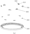
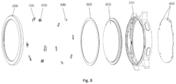
Fig. 8 is an explosive view of a wearable device provided by some examples of the disclosure. - Some examples of the invention are described in detail below in conjunction with the accompanying drawings. It is to be understood that some examples described here are merely used to illustrate and explain the invention and are not used to limit the invention.
- In the invention, in the absence of any indication to the contrary, the use of orientation terms such as "inside and outside" is defined based on a radial direction of a detachable or fixed structure to mean that the direction along the radius of the detachable or fixed structure towards the center of the circle is inside, and the direction along the center of the circle to the radius is outside. The terms "first" and "second" are used to distinguish one element from another and do not have sequentiality or significance. In addition, the following description refers to the accompanying drawings in such a way that the same reference numerals in the different drawings indicate the same or similar elements.
- According to some examples of the invention, a
wearable device 1 is provided. As shown inFig. 1 , thewearable device 1 includes: afixed structure 100; a processor10, where theprocessor 10 is installed on thefixed structure 100; and adetachable structure 200, thedetachable structure 200 is installed on thefixed structure 100 in a detachable mode, at least one group ofinductive pieces 20 are arranged on thedetachable structure 200, each group ofinductive pieces 20 includes at least oneinductive element 30, and at least onesensor 40 is arranged on thefixed structure 100. Thesensor 40 is configured to detect theinductive element 30 at a corresponding position, different types of at least one group ofinductive pieces 20 are arranged on different types ofdetachable structure 200, and theprocessor 10 is in communication connection with thesensor 40 so as to adjust a display of thewearable device 1 according to a detection result of thesensor 40. - Through the above technical solution, in the
wearable device 1 provided by the invention, because thewearable device 1 includes thefixed structure 100 and thedetachable structure 200, and thedetachable structure 200 can be installed on thefixed structure 100 in a detachable mode, thewearable device 1 can realize that the different types ofdetachable structures 200 are replaced on the samefixed structure 100, thus achieving detaching of thedetachable structure 200. In addition, because theinductive element 30 is arranged on thedetachable structure 200, thesensor 40 is arranged on thefixed structure 100, and thesensor 40 can detect theinductive element 30 at the corresponding position, when thedetachable structure 200 is installed on thefixed structure 100, thesensor 40 can detect theinductive element 30 corresponding to the currentdetachable structure 200, and theprocessor 10 adjusts a display of the wearable 1 device according to a detection result of thesensor 40 so that the display of thewearable device 1 matches with the currentdetachable structure 200. On this basis, the different types of at least one group ofinductive pieces 20 are arranged on the different types ofdetachable structures 200, that is, the different types ofdetachable structures 200 have different types of inductive pieces. Thus, according to thewearable device 1 of the invention, automatically adjusting the display of thewearable device 1 can further be easily achieved during replacement of thedetachable structure 200 and operation is convenient. - It needs to be noted that, the "different types of
detachable structures 200" may refer todetachable structures 200 in different appearances. An appearance of thedetachable structure 200 at least includes at least one of a color, a shape, a material, etc. of thedetachable structure 200. In other words, the "different types ofdetachable structures 200" may refer todetachable structures 200 different in at least one of the color, the shape, or the material. In addition, the "detection result" may be a type of the detachable structure detected by thesensor 40, that is, thesensor 40 may detect the type of the detachable structure through detecting the type of the at least one group ofinductive pieces 20. In addition, the "the display of thewearable device 1" may refer to display information on a touch control display screen in thewearable device 1. - In the invention, the
processor 10 may further adjust at least one of the display, vibration, and sound of thewearable device 1 according to the detection result. Theprocessor 10 may adjust at least one of display information of a dial plate, audio information broadcast by a speaker, or vibration information triggered by a motor according to the detection result, or may adjust a combination of any two of them, or may adjust the display information, audio information broadcast by the speaker and vibration information triggered by the motor at the same time. The above "dial plate" here may refer to information displayed on a display interface of thewearable device 1. - The "detachable structure" and the "fixed structure" here refer to the "detachable structure" and the "fixed structure" included in a body of the
wearable device 1. For example, the "detachable structure" may refer to a watch bezel of the body of thewearable device 1, and the "fixed structure" may refer to a middle frame of the body of thewearable device 1. In addition, "different types of at least one group ofinductive pieces 20 are arranged on different types ofdetachable structures 200" refers to that, at least one group ofinductive pieces 20 may be arranged on thedetachable structures 200, and for the same type ofdetachable structure 200, theinductive elements 30 at the same positions in each group ofinductive pieces 20 are the same; and for the different types ofdetachable structures 200, in each group ofinductive pieces 20, theinductive elements 30 at at least one same position are different, or at the same position, there may be a case that aninductive element 30 is arranged in one group while noinductive element 30 is arranged in another group. - In some examples of the invention, the
inductive elements 30 and thesensor 40 may be structured in any suitable mode. In some examples, theinductive elements 30 may be structured asmagnetic pieces 300, thesensor 40 may be structured as aHall device 400, and theHall device 400 is configured to detect magnetic pole information of themagnetic piece 300 at the corresponding position. It needs to be noted here that, the "different types of at least one group ofinductive pieces 20" may refer to that the magnetic pole information of themagnetic pieces 300 in different types of at least one group ofinductive pieces 20 is different. In some examples, theHall device 400 may detect the type of the at least one group ofinductive pieces 20 through detecting the magnetic pole information of themagnetic pieces 300, thus detecting the type of the detachable structure, and transmit a detection result, i.e. the detected type of the detachable structure, to theprocessor 10, and theprocessor 10 adjusts the display of thewearable device 1. In some examples, during replacement of different types ofdetachable structures 200, thedetachable structures 200 rotate relative to the fixedstructure 100, so themagnetic pieces 300 and theHall device 400 rotate from deflected positions with a relatively large distance to positions corresponding to each other. In a process when themagnetic pieces 300 gradually approach theHall device 400, a magnetic field strength of themagnetic pieces 300 is higher than a threshold value required by theHall device 400 so that theHall device 400 can generate a Hall effect. At the moment, theHall device 400 detects the magnetic pole information of themagnetic pieces 300 at the corresponding position. - In other examples, the
inductive elements 30 may be structured as structural members, thesensor 40 may be structured as an image recognition sensor, and the structural members may be protrusions. It needs to be noted here that, the "different types of at least one group ofinductive pieces 20" may refer to a case that the protrusions in the different types of at least one group ofinductive pieces 20 are different in shape or quantity. In the example, the image recognition sensor may detect the type of the at least one group ofinductive pieces 20 by detecting the shapes or quantity of the protrusions, thus detecting the type of the detachable structure, and transmit a detection result, i.e. the type of the detachable structure, to theprocessor 10, and theprocessor 10 adjusts the display of thewearable device 1. - In some examples of the invention, the
inductive pieces 20 may be structured in any suitable mode. In some examples, as shown inFig. 1 ,Fig. 5 andFig. 6 , at least two groups ofinductive pieces 20 may be arranged on thedetachable structure 200, the at least two groups ofinductive pieces 20 may be arranged at intervals in a circumferential direction of thedetachable structure 200, and any two groups ofinductive pieces 20 may be arranged in a rotationally symmetric mode. In the any two groups ofinductive pieces 20, poles of two correspondingmagnetic pieces 300 arranged in a rotationally symmetric mode may be the same. That is, in the same type ofdetachable structure 200, the magnetic pole information of themagnetic pieces 300 in each group ofinductive pieces 20 is the same. In this way, during installation of thedetachable structure 200, it is merely needed to make the positions of themagnetic pieces 300 in any one group ofinductive pieces 20 correspond to that of theHall device 400, and theHall device 400 can detect the magnetic pole information of the correspondingmagnetic pieces 300 so as to determine the type of the currentdetachable structure 200. - In addition, it needs to be noted that, "any two groups of
inductive pieces 20 may be arranged in a rotationally symmetric mode" may refer to a case that any two groups ofinductive pieces 20 are at the same interval angle. In this way, during installation of thedetachable structure 200, installation may be completed when thedetachable structure 200 is rotated by at most one interval angle relative to the fixedstructure 100. On the one hand, a rotation degree of thedetachable structure 200 during installation may be reduced, and installation is convenient; and on the other hand, compared to the arrangement of merely one group ofinductive pieces 20, the above arrangement can prevent the situation that in an installedwearable device 1, theHall device 400 fails to recognize the type of the currentdetachable structure 200 because themagnetic pieces 300 and theHall device 400 are at non-corresponding positions. For example, when a quantity of theinductive pieces 20 is three groups, "any two groups ofinductive pieces 20 may be arranged in a rotationally symmetric mode" may refer to a case that any two groups ofinductive pieces 20 are at the same interval angle of 120°. During installation of thedetachable structure 200, installation may be completed when thedetachable structure 200 is rotated by at most 120° relative to the fixedstructure 100. At the same time, after installation of thedetachable structure 200, there is always one group ofinductive pieces 20 among the three groups ofinductive pieces 20 at the position corresponding to the position of theHall device 400, so the situation that theinductive pieces 20 and theHall device 400 are at non-corresponding positions and the angular difference between theinductive pieces 20 and theHall device 400 is 120° or 240° will not be caused. - In some examples of the invention, the
magnetic pieces 300 in each group ofinductive pieces 20 may be structured in any suitable mode. In some examples, as shown inFig. 5 to Fig. 6 , thedetachable structure 200 may have an installingstructure 50 configured to install each group ofinductive pieces 20, and the installingstructure 50 may include at least two installinggrooves 210 used to install themagnetic pieces 300, where a quantity of theHall devices 400 may equal a quantity of the installinggrooves 210 in the installingstructure 50, and a quantity of themagnetic pieces 300 of each group ofinductive pieces 20 may be smaller than a quantity of the installinggrooves 210 in the installingstructure 50. In other words, there may be a case that in at least one installinggroove 210, nomagnetic piece 300 is installed. For example, when a quantity of the installinggrooves 210 in the installingstructure 50 is two (respectively labeled as thefirst installing groove 210a and thesecond installing groove 210b here), "the quantity of themagnetic pieces 300 of each group ofinductive pieces 20 may be smaller than a quantity of the installinggrooves 210 in the installingstructure 50" refers to a case that a quantity of themagnetic piece 300 in each group ofinductive pieces 20 is one, that is, themagnetic piece 300 is installed in one of thefirst installing groove 210a and thesecond installing groove 210b, and nomagnetic piece 300 is installed in the other of the two. Because the magnetic pole information of themagnetic pieces 300 includes an N pole and an S pole, when a quantity of the installinggrooves 210 in the installingstructure 50 is two, there will be four different types of correspondingdetachable structures 200 as follows. - I. The
magnetic piece 300 is installed in thefirst installing groove 210a, and in a case of completing installation of thedetachable structure 200, the N pole of themagnetic piece 300 can be detected by theHall device 400; and nomagnetic piece 300 is installed in thesecond installing groove 210b. In this case, the type of thedetachable structure 200 is recorded as a first detachable structure, and the corresponding magnetic pole information detected by theHall device 400 is: N/. II. Themagnetic piece 300 is installed in thefirst installing groove 210a, and in a case of completing installation of thedetachable structure 200, the S pole of themagnetic piece 300 can be detected by theHall device 400; and nomagnetic piece 300 is installed in thesecond installing groove 210b. In this case, the type of thedetachable structure 200 is recorded as a second detachable structure, and the corresponding magnetic pole information detected by theHall device 400 is: S/. III. Nomagnetic piece 300 is installed in thefirst installing groove 210a, themagnetic piece 300 is installed in thesecond installing groove 210b, and in a case of completing installation of thedetachable structure 200, the N pole of themagnetic piece 300 can be detected by theHall device 400. In this case, the type of thedetachable structure 200 is recorded as a third detachable structure, and the corresponding magnetic pole information detected by theHall device 400 is: /N. IV. Nomagnetic piece 300 is installed in thefirst installing groove 210a, themagnetic piece 300 is installed in thesecond installing groove 210b, and in a case of completing installation of thedetachable structure 200, the S pole of themagnetic piece 300 can be detected by theHall device 400. In this case, the type of thedetachable structure 200 is recorded as a fourth detachable structure, and the corresponding magnetic pole information detected by theHall device 400 is: /S. - In some other examples, the
detachable structure 200 may have the installingstructure 50 configured to install each group ofinductive pieces 20, and the installingstructure 50 may include at least two installinggrooves 210 used to install themagnetic pieces 300, where a quantity of theHall devices 400 may equal a quantity of the installinggrooves 210 in the installingstructure 50, and a quantity of themagnetic pieces 300 of each group ofinductive pieces 20 may equal a quantity of the installinggrooves 210 in the installing structure. In other words, themagnetic piece 300 is installed in each installinggroove 210. For example, when a quantity of the installinggrooves 210 in the installingstructure 20 is two (respectively labeled as thefirst installing groove 210a and thesecond installing groove 210b here), "the quantity of themagnetic pieces 300 of each group ofinductive pieces 20 may equal a quantity of the installinggrooves 210 in the installingstructure 50" refers to a case that a quantity ofmagnetic pieces 300 in each group ofinductive pieces 20 is two, that is, themagnetic pieces 300 are installed in both thefirst installing groove 210a andsecond installing groove 210b. Because the magnetic pole information of themagnetic pieces 300 includes an N pole and an S pole, when a quantity of the installinggrooves 210 in the installingstructure 50 is two, there will be four different types of correspondingdetachable structures 200 as follows. - I. The
magnetic pieces 300 are installed in both thefirst installing groove 210a andsecond installing groove 210b, and in a case of completing installation of thedetachable structure 200, the N pole of themagnetic piece 300 in thefirst installing groove 210a and the N pole of themagnetic piece 300 in thesecond installing groove 210b can be respectively detected by the correspondingHall device 400. In this case, the type of thedetachable structure 200 is recorded as a fifth detachable structure, and the corresponding magnetic pole information detected by theHall device 400 is: NN. II. Themagnetic pieces 300 are installed in both thefirst installing groove 210a andsecond installing groove 210b, and in a case of completing installation of thedetachable structure 200, the N pole of themagnetic piece 300 in thefirst installing groove 210a and the S pole of themagnetic piece 300 in thesecond installing groove 210b can be respectively detected by the correspondingHall device 400. In this case, the type of thedetachable structure 200 is recorded as a sixth detachable structure, and the corresponding magnetic pole information detected by theHall device 400 is: NS. III. Themagnetic pieces 300 are installed in both thefirst installing groove 210a andsecond installing groove 210b, and in a case of completing installation of thedetachable structure 200, the S pole of themagnetic piece 300 in thefirst installing groove 210a and the N pole of themagnetic piece 300 in thesecond installing groove 210b can be respectively detected by the correspondingHall device 400. In this case, the type of thedetachable structure 200 is recorded as a seventh detachable structure, and the corresponding magnetic pole information detected by theHall device 400 is: SN. IV. Themagnetic pieces 300 are installed in both thefirst installing groove 210a andsecond installing groove 210b, and in a case of completing installation of thedetachable structure 200, the S pole of themagnetic piece 300 in thefirst installing groove 210a and the S pole of themagnetic piece 300 in thesecond installing groove 210b can be respectively detected by the correspondingHall device 400. In this case, the type of thedetachable structure 200 is recorded as an eighth detachable structure, and the corresponding magnetic pole information detected by theHall device 400 is: SS. - In other examples, installing
groups 210 in other suitable quantity may also be arranged in the installingstructure 50. For example, a quantity of the installinggrooves 210 in the installingstructure 50 may be three, four, etc., which is not specifically limited in the invention. At the same time, a quantity of theHall devices 400 may equal a quantity of the installinggrooves 210, and a quantity of themagnetic pieces 300 may be smaller than or equal a quantity of the installinggrooves 210. - In some examples of the invention, the
detachable structure 200 may be installed on the fixedstructure 100 in a detachable mode in any suitable way. In some examples, as shown inFig. 3 to Fig. 6 , the fixedstructure 100 may have anannular matching part 110, and thedetachable structure 200 may be rotatably sleeved in theannular matching part 110. Afirst turnbuckle 510 may be arranged on theannular matching part 110, asecond turnbuckle 520 may be arranged on thedetachable structure 200, and thefirst turnbuckle 510 and thesecond turnbuckle 520 may be clamped together in a rotatably fastening mode. Thefirst turnbuckle 510 may be arranged as one of a fastener or a clamping groove, and thesecond turnbuckle 520 may be arranged as the other. In this way, when thedetachable structure 200 rotates relative to theannular matching part 110, the fastener can also rotate relative to the clamping groove and be clamped in the clamping groove. On the one hand, installation of thedetachable structure 200 and the fixedstructure 100 can be realized through rotation, and operation is convenient; and on the other hand, detachment of thedetachable structure 200 from the fixedstructure 100 can be prevented, and it is ensured that thedetachable structure 200 is firmly installed. - In the example, as shown in
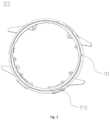
Fig. 4 , an L-shaped baffle may be arranged on an outer side wall of theannular matching part 110, the L-shaped baffle may include a first stoppingpart 511 and a second stoppingpart 512, and the first stoppingpart 511, the second stoppingpart 512 and a frame body of the fixedstructure 100 may jointly define a U-shaped clamping groove with an open end. The U-shaped clamping groove is arranged in a circumferential direction of theannular matching part 110 so as to be used as thefirst turnbuckle 510. As shown inFig. 6 , blocking chunks may be arranged on an inner side wall of thedetachable structure 200, the blocking chunks may be arranged in the circumferential direction of thedetachable structure 200 so as to be used as thesecond turnbuckle 520. In this way, when thedetachable structure 200 rotates relative to the fixedstructure 100, the blocking chunks (that is, the second turnbuckle 520) can also rotate relative to the U-shaped clamping groove (that is, the first turnbuckle 510) so as to enter the U-shaped clamping groove (that is, the first turnbuckle 510) from the open end of the U-shaped clamping groove (that is, the first turnbuckle 510). At the moment, the first stoppingpart 511 and the frame body of the fixedstructure 100 can jointly restrict the blocking chunks (that is, the second turnbuckle 520) from moving in an axial direction of thedetachable structure 200 relative to the U-shaped clamping groove (that is, the first turnbuckle 510), that is, restricting thedetachable structure 200 from being detached from the fixedstructure 100 along the axial direction of thedetachable structure 200. In addition, through the arrangement of the second stoppingpart 512, the blocking chunks (that is, the second turnbuckle 520) can be restricted from further rotating relative to the U-shaped clamping groove (that is, the first turnbuckle 510), that is, thedetachable structure 200 is restricted from further rotating relative to the fixedstructure 100, which reminds an operator of completing installation of thedetachable structure 200. It needs to be noted that, when the blocking chunks abut against the second stoppingpart 512, thedetachable structure 200 and the fixedstructure 100 are in an installed status, and at the moment, eachHall device 400 can also detect the magnetic pole information of the correspondingmagnetic piece 300. - In addition, in the example, a quantity of the
first turnbuckles 510 andsecond turnbuckles 520 may be plural, thefirst turnbuckles 510 andsecond turnbuckles 520 may be arranged respectively in one-to-one correspondence. The plurality offirst turnbuckles 510 may be arranged at intervals in the circumferential direction of theannular matching part 110, and the plurality ofsecond turnbuckles 520 may be arranged at intervals in the circumferential direction of thedetachable structure 200. In this way, one circumference of thedetachable structure 200 may be firmly installed on the fixedstructure 100 through thefirst turnbuckles 510 andsecond turnbuckles 520, thus increasing connection stability. In other examples, thefirst turnbuckles 510 andsecond turnbuckles 520 may also be structured in other suitable modes, which is not restricted in the invention. - In some examples of the invention, in order to reduce friction between the fixed
structure 100 and thedetachable structure 200, in some examples, referring toFig. 2 , and as shown inFig. 6 to Fig. 7 , the fixedstructure 100 may have theannular matching part 110, thedetachable structure 200 may be rotatably sleeved in theannular matching part 110, aflexible piece 600 may be arranged on one of theannular matching part 110 and thedetachable structure 200, and theflexible piece 600 may abut against the other of theannular matching part 110 and thedetachable structure 200. In this way, theflexible piece 600 may be arranged between theannular matching part 110 and thedetachable structure 200, and offer buffering during relative rotation between theannular matching part 110 and thedetachable structure 200, thus preventing hard contact between theannular matching part 110 and thedetachable structure 200, and reducing wearing between theannular matching part 110 and thedetachable structure 200. In the example, afirst locating groove 220 for installing theflexible piece 600 may be formed on thedetachable structure 200, theflexible piece 600 may be partially accommodated in thefirst locating groove 220 and be bonded in thefirst locating groove 220 through glue dispensing, so that an installing position of theflexible piece 600 can be conveniently determined in a processing course. In addition, in the example, a quantity of theflexible piece 600 may be plural, and the plurality offlexible pieces 600 are arranged at intervals in the circumferential direction of thedetachable structure 200. In this way, an effect of comprehensive protection may be achieved on the circumference of thedetachable structure 200. - The
flexible piece 600 may be structured in any suitable mode. In some examples, as shown inFig. 2 andFig. 6 , theflexible piece 600 may be arranged on thedetachable structure 200, theflexible piece 600 may have afirst wall surface 610, and thefirst wall surface 610 may be used to abut against the fixedstructure 100 in an axial direction. In this way, thefirst wall surface 610 may prevent hard contact between theannular matching part 110 and thedetachable structure 200 in the axial direction. - In addition, as shown in
Fig. 2 ,Fig. 6 andFig. 7 , theflexible piece 600 may be arranged on thedetachable structure 200, theflexible piece 600 may have asecond wall surface 620, and thesecond wall surface 620 may be used to abut against theannular matching part 110 in a radial direction. In this way, thesecond wall surface 620 can prevent hard contact between theannular matching part 110 and thedetachable structure 200 in a radial direction. - In some examples of the invention, referring to
Fig. 3 to Fig. 4 , and as shown inFig. 6 to Fig. 7 , the fixedstructure 100 may have theannular matching part 110, thedetachable structure 200 may be rotatably sleeved in theannular matching part 110, anelastic sheet 700 may be arranged on thedetachable structure 200, theelastic sheet 700 may have afirst protrusion 710 that protrudes inwardly, asecond protrusion 111 that protrudes outwardly may be arranged on theannular matching part 110, and when thedetachable structure 200 rotates, thefirst protrusion 710 may selectively abut against thesecond protrusion 111. In this way, in a process of rotation of thedetachable structure 200 relative to the fixedstructure 100, theelastic sheet 700 is in contact with thesecond protrusion 111, and at the moment theelastic sheet 700 can move outward in the radial direction of thedetachable structure 200 under an abutting effect of thesecond protrusion 111; and when installation of thedetachable structure 200 is completed, theelastic sheet 700 can bypass thesecond protrusion 111, and at the moment, theelastic sheet 700 can move inward in the radial direction of thedetachable structure 200 under an elastic effect of the elastic sheet and strike theannular matching part 110 to cause vibration and make a sound, which reminds the operator of completed installation of thedetachable structure 200. In addition, through the arrangement of thefirst protrusion 710 that protrudes inwardly on theelastic sheet 700, when thefirst protrusion 710 abuts against thesecond protrusion 111, a distance between theelastic sheet 700 and theannular matching part 110 can be enlarged, so a striking degree of theelastic sheet 700 against theannular matching part 110 is also clearer. In the example, a quantity of theelastic sheet 700 and thesecond protrusion 111 may be set to be one or plural, and theelastic sheet 700 and thesecond protrusion 111 are arranged in one-to-one correspondence. When there is a plurality ofelastic sheets 700, the plurality ofelastic sheets 700 may be distributed at intervals in the circumferential direction of thedetachable structure 200. In this way, a reminding effect for the operator caused by theelastic sheets 700 may be further enhanced. - In the example, the
first protrusion 710 and thesecond protrusion 111 may be arranged in an arc shape on both sides, which facilitates the situation that theelastic sheet 700 is in smooth contact with thesecond protrusion 111 during rotation, and elastic deformation is caused to prevent clamping of theelastic sheet 700. In addition, asecond locating groove 230 for installing theelastic sheet 700 may be arranged on thedetachable structure 200, theelastic sheet 700 may be partially accommodated in thesecond locating groove 230 and be installed in thesecond locating groove 230 through laser welding or other modes, and in this way, an installing position of theelastic sheet 700 can be conveniently determined in a processing course. - In some other examples, two second protrusions 111 (not shown in the drawings) may also be arranged. In this way, after completing installation of the
detachable structure 200, theelastic sheet 700 can be located between the twosecond protrusions 111. On the one hand, the purpose of reminding the operator through vibration and sounds can be achieved, and on the other hand, over rotation of thedetachable structure 200 by the operator can be prevented through restricting the position of theelastic sheet 700 by the twosecond protrusions 111. - On the basis of the above solution, as shown in
Fig. 8 , thewearable device 1 may further include an installingring 800 and acover plate 900. Thecover plate 900 may be arranged on the fixedstructure 100 in a shading mode. In this way, thecover plate 900 can provide protection for thewearable device 1 so as to prevent thewearable device 1 from knocking damage. The installingring 800 may be arranged between thecover plate 900 and thedetachable structure 200. In this way, thedetachable structure 200 can be prevented from scratching thecover plate 900 in a rotating process. In addition, a third locating groove for installing the installingring 800 may further be formed in thedetachable structure 200. - In summary, during replacement of the
detachable structure 200 of thewearable device 1, the operator may rotate thedetachable structure 200 to achieve rotatable fastening between thefirst turnbuckle 510 and thesecond turnbuckle 520, and a reminding sound made by theelastic sheet 700 and vibration indicate that thedetachable structure 200 has been installed in place; and at the moment, it is no longer needed to rotate thedetachable structure 200. TheHall device 400 can detect the magnetic pole information of the correspondingmagnetic piece 300 so as to determine the type of the currentdetachable structure 200. Then theprocessor 10 may adjust the display of thewearable device 1 according to a detection result of theHall device 400. In this way, instant switching of the corresponding display of thewearable device 1 may be realized during replacement of different types of detachable structures.
Claims (10)
- A wearable device (1), comprising:a fixed structure (100);a processor (10), installed on the fixed structure (100); anda detachable structure (200), installed on the fixed structure (100) in a detachable mode,wherein at least one group of inductive pieces (20) are arranged on the detachable structure (200), each group of inductive pieces (20) comprises at least one inductive element (30), and at least one sensor (40) is arranged on the fixed structure (100), wherein the sensor (40) is configured to detect the inductive element (30) at a corresponding position, different types of the at least one group of inductive pieces (20) are arranged on different types of detachable structures (200), and the processor (10) is in communication connection with the sensor (40) so as to adjust a display of the wearable device (1) according to a detection result of the sensor (40).
- The wearable device (1) according to claim 1, wherein the inductive element (30) is structured as a magnetic piece (300), the sensor (40) is structured as a Hall device (400), and the Hall device (400) is configured to detect magnetic pole information of the magnetic piece (300) at a corresponding position.
- The wearable device (1) according to claim 2, wherein at least two groups of inductive pieces (20) are arranged on the detachable structure (200), at least two groups of the inductive pieces (20) are arranged at intervals in a circumferential direction of the detachable structure (200), and any two groups of inductive pieces (20) are arranged in a rotationally symmetric mode, wherein in the any two groups of inductive pieces (20), magnetic poles of two corresponding magnetic pieces (300) arranged in a rotationally symmetric mode are the same.
- The wearable device (1) according to claim 3, wherein the detachable structure (200) has an installing structure (50) configured to install each group of inductive pieces (20), and the installing structure (50) comprises at least two installing grooves (210) used to install the magnetic pieces (300), wherein a quantity of the Hall devices (400) is equal to a quantity of the installing grooves (210) in the installing structure (50), and a quantity of the magnetic pieces (300) of each group of inductive pieces (20) is smaller than a quantity of the installing grooves (210) in the installing structure (50).
- The wearable device (1) according to claim 3, wherein the detachable structure (200) has an installing structure (50) configured to install each group of inductive pieces (20), and the installing structure (50) comprises at least two installing grooves (210) used to install the magnetic pieces (300), wherein a quantity of the Hall devices (400) equals a quantity of the installing grooves (210) in the installing structure (50), and a quantity of the magnetic pieces (300) of each group of inductive pieces (20) equals a quantity of the installing grooves (210) in the installing structure (50).
- The wearable device (1) according to any one of claims 1 to 5, wherein the fixed structure (100) has an annular matching part (110), and the detachable structure (200) is rotatably sleeved in the annular matching part (110), and
a first turnbuckle (510) is arranged on the annular matching part (110), a second turnbuckle (520) is arranged on the detachable structure (200), and the first turnbuckle (510) and the second turnbuckle (520) are clamped together in a rotatably fastening mode. - The wearable device (1) according to any one of claim 1 to 6, wherein the fixed structure (100) has an annular matching part (110), and the detachable structure (200) is rotatably sleeved in the annular matching part (110), and
a flexible piece (600) is arranged on one of the annular matching part (110) and the detachable structure (200), and the flexible piece (600) abuts against the other of the annular matching part (110) and the detachable structure (200). - The wearable device (1) according to claim 7, wherein the flexible piece (600) is arranged on the detachable structure (200), the flexible piece (600) has a first wall surface (610), and the first wall surface (610) is used to abut against the fixed structure (100) in an axial direction.
- The wearable device (1) according to claim 7 or 8, wherein the flexible piece (600) is arranged on the detachable structure (200), the flexible piece (600) has a second wall surface (620), and the second wall surface (620) is used to abut against the annular matching part (110) in a radial direction.
- The wearable device (1) according to any one of claim 1 to 9, wherein the fixed structure (100) has an annular matching part (110), and the detachable structure (200) is rotatably sleeved in the annular matching part (110), and
an elastic sheet (700) is arranged on the detachable structure (200), the elastic sheet (700) has a first protrusion (710) that protrudes inwardly, the annular matching part (110) is provided with a second protrusion (111) that protrudes outwardly, and in response to determining that the detachable structure (200) rotates, the first protrusion (710) selectively abuts against the second protrusion (111).
Applications Claiming Priority (1)
| Application Number | Priority Date | Filing Date | Title |
|---|---|---|---|
| CN202311345103.7A CN119847319A (en) | 2023-10-17 | 2023-10-17 | Wearing equipment |
Publications (1)
| Publication Number | Publication Date |
|---|---|
| EP4542333A1 true EP4542333A1 (en) | 2025-04-23 |
Family
ID=90923959
Family Applications (1)
| Application Number | Title | Priority Date | Filing Date |
|---|---|---|---|
| EP24173192.6A Pending EP4542333A1 (en) | 2023-10-17 | 2024-04-29 | Wearable device |
Country Status (3)
| Country | Link |
|---|---|
| US (1) | US20250123599A1 (en) |
| EP (1) | EP4542333A1 (en) |
| CN (1) | CN119847319A (en) |
Citations (4)
| Publication number | Priority date | Publication date | Assignee | Title |
|---|---|---|---|---|
| EP2270628A1 (en) * | 2009-06-30 | 2011-01-05 | Research In Motion Limited | Overlay for electronic device and method of identifying same |
| KR20160087673A (en) * | 2015-01-14 | 2016-07-22 | 엘지전자 주식회사 | Watch type terminal |
| US20180157217A1 (en) * | 2015-05-27 | 2018-06-07 | Lg Electronics Inc. | Watch-type mobile terminal and operation method thereof |
| CN219574618U (en) * | 2023-02-27 | 2023-08-22 | 合肥龙旗智能科技有限公司 | Watch decoration assembly |
-
2023
- 2023-10-17 CN CN202311345103.7A patent/CN119847319A/en active Pending
-
2024
- 2024-04-29 EP EP24173192.6A patent/EP4542333A1/en active Pending
- 2024-05-13 US US18/662,340 patent/US20250123599A1/en active Pending
Patent Citations (4)
| Publication number | Priority date | Publication date | Assignee | Title |
|---|---|---|---|---|
| EP2270628A1 (en) * | 2009-06-30 | 2011-01-05 | Research In Motion Limited | Overlay for electronic device and method of identifying same |
| KR20160087673A (en) * | 2015-01-14 | 2016-07-22 | 엘지전자 주식회사 | Watch type terminal |
| US20180157217A1 (en) * | 2015-05-27 | 2018-06-07 | Lg Electronics Inc. | Watch-type mobile terminal and operation method thereof |
| CN219574618U (en) * | 2023-02-27 | 2023-08-22 | 合肥龙旗智能科技有限公司 | Watch decoration assembly |
Also Published As
| Publication number | Publication date |
|---|---|
| US20250123599A1 (en) | 2025-04-17 |
| CN119847319A (en) | 2025-04-18 |
Similar Documents
| Publication | Publication Date | Title |
|---|---|---|
| EP0753679B1 (en) | Rolling bearing unit having tone wheel | |
| US9057883B2 (en) | Image shake correcting device, lens barrel, optical apparatus, and image pickup apparatus | |
| EP1134540A1 (en) | Magnetic rotation detector | |
| US11656062B2 (en) | Apparatus and method for indicating whether a target has been impacted by a projectile | |
| JPH08313790A (en) | Shooting lens feeding device | |
| EP4542333A1 (en) | Wearable device | |
| US8670196B2 (en) | Lens barrel | |
| JP2019144008A (en) | Crime prevention sensor device | |
| JP2001004405A (en) | Magnetic encoder device | |
| US20250255446A1 (en) | Roller brush assembly, cleaning device, detection method, and storage medium | |
| CN212367511U (en) | But rotary control's earphone | |
| EP0481884B1 (en) | Mechanism for detecting a rotation amount of a diaphragm for use in optical systems | |
| US20100265806A1 (en) | Rotation angle sensor | |
| JPH07134047A (en) | Multi-turn encoder | |
| WO2023273037A1 (en) | Wearable apparatus | |
| WO2026037018A1 (en) | Support assembly | |
| US11682511B2 (en) | Electronic apparatus | |
| US20230073974A1 (en) | Display device | |
| WO2023005010A1 (en) | Wristband device with switchable screen | |
| JP2000316147A5 (en) | How to adjust compound camera and compound camera | |
| JPH063159A (en) | Multi-rotary rotary encoder | |
| JP2011149532A (en) | Rolling bearing device with rotation sensor | |
| CN113747000A (en) | Prompter device for broadcasting host capable of being rapidly switched | |
| CN216410232U (en) | Sensor with firm installation and connection | |
| JPH02218389A (en) | needle position detector |
Legal Events
| Date | Code | Title | Description |
|---|---|---|---|
| PUAI | Public reference made under article 153(3) epc to a published international application that has entered the european phase |
Free format text: ORIGINAL CODE: 0009012 |
|
| STAA | Information on the status of an ep patent application or granted ep patent |
Free format text: STATUS: REQUEST FOR EXAMINATION WAS MADE |
|
| 17P | Request for examination filed |
Effective date: 20240429 |
|
| AK | Designated contracting states |
Kind code of ref document: A1 Designated state(s): AL AT BE BG CH CY CZ DE DK EE ES FI FR GB GR HR HU IE IS IT LI LT LU LV MC ME MK MT NL NO PL PT RO RS SE SI SK SM TR |
|
| STAA | Information on the status of an ep patent application or granted ep patent |
Free format text: STATUS: EXAMINATION IS IN PROGRESS |
|
| 17Q | First examination report despatched |
Effective date: 20260310 |