EP4542308A1 - Process cartridge - Google Patents
Process cartridge Download PDFInfo
- Publication number
- EP4542308A1 EP4542308A1 EP24206368.3A EP24206368A EP4542308A1 EP 4542308 A1 EP4542308 A1 EP 4542308A1 EP 24206368 A EP24206368 A EP 24206368A EP 4542308 A1 EP4542308 A1 EP 4542308A1
- Authority
- EP
- European Patent Office
- Prior art keywords
- wall
- cartridge
- developing
- pressure
- drum
- Prior art date
- Legal status (The legal status is an assumption and is not a legal conclusion. Google has not performed a legal analysis and makes no representation as to the accuracy of the status listed.)
- Pending
Links
Images




Classifications
-
- G—PHYSICS
- G03—PHOTOGRAPHY; CINEMATOGRAPHY; ANALOGOUS TECHNIQUES USING WAVES OTHER THAN OPTICAL WAVES; ELECTROGRAPHY; HOLOGRAPHY
- G03G—ELECTROGRAPHY; ELECTROPHOTOGRAPHY; MAGNETOGRAPHY
- G03G15/00—Apparatus for electrographic processes using a charge pattern
- G03G15/06—Apparatus for electrographic processes using a charge pattern for developing
- G03G15/08—Apparatus for electrographic processes using a charge pattern for developing using a solid developer, e.g. powder developer
- G03G15/0822—Arrangements for preparing, mixing, supplying or dispensing developer
- G03G15/0865—Arrangements for supplying new developer
-
- G—PHYSICS
- G03—PHOTOGRAPHY; CINEMATOGRAPHY; ANALOGOUS TECHNIQUES USING WAVES OTHER THAN OPTICAL WAVES; ELECTROGRAPHY; HOLOGRAPHY
- G03G—ELECTROGRAPHY; ELECTROPHOTOGRAPHY; MAGNETOGRAPHY
- G03G15/00—Apparatus for electrographic processes using a charge pattern
- G03G15/06—Apparatus for electrographic processes using a charge pattern for developing
- G03G15/08—Apparatus for electrographic processes using a charge pattern for developing using a solid developer, e.g. powder developer
- G03G15/0822—Arrangements for preparing, mixing, supplying or dispensing developer
- G03G15/0865—Arrangements for supplying new developer
- G03G15/0867—Arrangements for supplying new developer cylindrical developer cartridges, e.g. toner bottles for the developer replenishing opening
- G03G15/087—Developer cartridges having a longitudinal rotational axis, around which at least one part is rotated when mounting or using the cartridge
-
- G—PHYSICS
- G03—PHOTOGRAPHY; CINEMATOGRAPHY; ANALOGOUS TECHNIQUES USING WAVES OTHER THAN OPTICAL WAVES; ELECTROGRAPHY; HOLOGRAPHY
- G03G—ELECTROGRAPHY; ELECTROPHOTOGRAPHY; MAGNETOGRAPHY
- G03G15/00—Apparatus for electrographic processes using a charge pattern
- G03G15/06—Apparatus for electrographic processes using a charge pattern for developing
- G03G15/08—Apparatus for electrographic processes using a charge pattern for developing using a solid developer, e.g. powder developer
- G03G15/0822—Arrangements for preparing, mixing, supplying or dispensing developer
- G03G15/0877—Arrangements for metering and dispensing developer from a developer cartridge into the development unit
- G03G15/0881—Sealing of developer cartridges
-
- G—PHYSICS
- G03—PHOTOGRAPHY; CINEMATOGRAPHY; ANALOGOUS TECHNIQUES USING WAVES OTHER THAN OPTICAL WAVES; ELECTROGRAPHY; HOLOGRAPHY
- G03G—ELECTROGRAPHY; ELECTROPHOTOGRAPHY; MAGNETOGRAPHY
- G03G21/00—Arrangements not provided for by groups G03G13/00 - G03G19/00, e.g. cleaning, elimination of residual charge
- G03G21/16—Mechanical means for facilitating the maintenance of the apparatus, e.g. modular arrangements
- G03G21/18—Mechanical means for facilitating the maintenance of the apparatus, e.g. modular arrangements using a processing cartridge, whereby the process cartridge comprises at least two image processing means in a single unit
- G03G21/1803—Arrangements or disposition of the complete process cartridge or parts thereof
- G03G21/1817—Arrangements or disposition of the complete process cartridge or parts thereof having a submodular arrangement
- G03G21/1821—Arrangements or disposition of the complete process cartridge or parts thereof having a submodular arrangement means for connecting the different parts of the process cartridge, e.g. attachment, positioning of parts with each other, pressure/distance regulation
-
- G—PHYSICS
- G03—PHOTOGRAPHY; CINEMATOGRAPHY; ANALOGOUS TECHNIQUES USING WAVES OTHER THAN OPTICAL WAVES; ELECTROGRAPHY; HOLOGRAPHY
- G03G—ELECTROGRAPHY; ELECTROPHOTOGRAPHY; MAGNETOGRAPHY
- G03G2221/00—Processes not provided for by group G03G2215/00, e.g. cleaning or residual charge elimination
- G03G2221/16—Mechanical means for facilitating the maintenance of the apparatus, e.g. modular arrangements and complete machine concepts
- G03G2221/18—Cartridge systems
- G03G2221/183—Process cartridge
- G03G2221/1853—Process cartridge having a submodular arrangement
Definitions
- the present invention relates to a process cartridge.
- the drum cartridge includes a photosensitive drum, pressing members, and a drum frame supporting the photosensitive drum and the pressing members.
- the pressing members press the developing cartridge toward the photosensitive drum.
- the developing cartridge includes a developing roller, and a developing frame supporting the developing roller. In the state where the developing cartridge is attached to the drum cartridge with this technology, a wall of the developing frame that is positioned at an end portion far from the photosensitive drum is pressed by the pressing members.
- a loss in a pressing force occurs when the drum frame deforms due to a reaction force that the pressing members receive from the developing cartridge in reaction to the pressing force of the pressing members. This loss of the pressing force caused by deformation of the drum frame is greater when the pressing members are configured to press the end portion of the developing frame that is far from the photosensitive drum.
- the pressing members can press the developing cartridge toward the photosensitive drum at positions close to the photosensitive drum.
- an image forming apparatus 1 includes a housing 2, a sheet-feeding unit 3, an exposure unit 4, a process cartridge 5, and a fixing unit 8.
- the sheet-feeding unit 3 is positioned at a lower portion inside the housing 2.
- the sheet-feeding unit 3 includes a sheet tray 31, a lifter plate 32, and a sheet-feeding mechanism 33.
- the sheet tray 31 is configured to accommodate therein sheets S of paper or the like.
- the lifter plate 32 is configured to lift the sheets S accommodated in the sheet tray 31 upward.
- the sheet-feeding mechanism 33 is configured to feed the sheets S lifted upward by the lifter plate 32 toward the process cartridge 5.
- the exposure unit 4 is positioned upward of the sheet tray 31.
- the exposure unit 4 includes a light source, a deflector, lenses, mirrors, and the like.
- the exposure unit 4 is configured to emit a laser beam as indicated by a phantom line in Fig. 1 in order to expose a surface of a photosensitive drum 61 to light.
- the process cartridge 5 is positioned upward of the sheet-feeding mechanism 33.
- the process cartridge 5 includes a drum cartridge 6, and a developing cartridge 7.
- the drum cartridge 6 includes the photosensitive drum 61, a charger 62, a transfer roller 63, and a drum frame 65.
- the photosensitive drum 61 is rotatable about a drum axis 61X extending in the first direction.
- the first direction corresponds to a left-right direction of the image forming apparatus 1.
- the charger 62 is configured to charge the surface of the photosensitive drum 61.
- the transfer roller 63 is rotatable about a transfer-roller axis 63X extending in the first direction.
- the drum frame 65 holds the photosensitive drum 61, the charger 62, and the transfer roller 63.
- the developing cartridge 7 includes a developing roller 71, a supply roller 72, a thickness-regulating blade 73, an agitator 74, and a developing frame 75.
- the developing roller 71 is rotatable about a developing-roller axis 71X extending in the first direction.
- the supply roller 72 is rotatable about a supply-roller axis 72X extending in the first direction.
- the thickness-regulating blade 73 is configured to regulate a layer of toner on the developing roller 71 so that the layer is formed to have a constant thickness.
- the developing frame 75 holds the developing roller 71, the supply roller 72, the thickness-regulating blade 73, and the agitator 74.
- the developing frame 75 is configured to accommodate therein toner.
- the developing frame 75 has a toner-accommodating portion 76 configured to accommodate therein toner.
- the agitator 74 is rotatable about an agitator axis 74X extending in the first direction. By rotating, the agitator 74 is configured to agitate toner in the toner-accommodating portion 76.
- the supply roller 72 is configured to supply toner accommodated in the toner-accommodating portion 76 to the developing roller 71.
- the fixing unit 8 is positioned upward of the process cartridge 5.
- the fixing unit 8 includes a heating roller 81, and a pressure roller 82.
- the heating roller 81 is configured to heat the sheets S.
- the pressure roller 82 is configured to nip the sheets S at a position between the pressure roller 82 and the heating roller 81.
- the image forming apparatus 1 charges the surface of the photosensitive drum 61 using the charger 62.
- the image forming apparatus 1 subsequently exposes the charged surface of the photosensitive drum 61 to light with a laser beam emitted from the exposure unit 4.
- an electrostatic latent image is formed on the photosensitive drum 61 based on image data.
- the image forming apparatus 1 supplies toner from the developing roller 71 onto the photosensitive drum 61, thereby forming a toner image on the photosensitive drum 61.
- the image forming apparatus 1 subsequently conveys a sheet S supplied from the sheet-feeding unit 3 at a position between the photosensitive drum 61 and the transfer roller 63, whereby the toner image formed on the photosensitive drum 61 is transferred onto the sheet S. Thereafter, the image forming apparatus 1 conveys the sheet S on which the toner image has been transferred at a position between the heating roller 81 and the pressure roller 82. As a result, the toner image transferred onto the sheet S is fixed to the sheet S.
- the image forming apparatus 1 discharges the sheet S on which the toner image has been fixed onto a discharge tray 2A.
- the housing 2 has a housing body 21, and a cover 22.
- the housing body 21 has an opening 21A.
- the cover 22 is configured to open and close the opening 21A.
- the cover 22 is movable relative to the housing body 21 between a closed position illustrated in Fig. 1 and an open position illustrated in Fig. 2 .
- the cover 22 is pivotally movable relative to the housing body 21 between the closed position and the open position. In the closed position, the cover 22 closes the opening 21A. In the open position, the cover 22 opens the opening 21A.
- the process cartridge 5 is attachable to and detachable from the housing 2. Specifically, the process cartridge 5 is attachable to and detachable from the housing body 21 through the opening 21A in a state where the cover 22 is in the open position.
- FIG. 3A illustrates the process cartridge 5 in which the developing cartridge 7 is attached to the drum cartridge 6.
- Fig. 3B illustrates a state where the developing cartridge 7 is detached from the drum cartridge 6.
- each arrow points to one side in the corresponding direction. Specifically, a leading side of each arrow represents one side in the corresponding direction, and a trailing side of each arrow represents the other side in the corresponding direction.
- the second direction is orthogonal to the first direction.
- the third direction is orthogonal to both the first direction and the second direction.
- the drum cartridge 6 further includes a locking lever 140, a first pressing member 150A, and a second pressing member 150B.
- the drum frame 65 has a first drum end portion 65A, and a second drum end portion 65B.
- Each of the first pressing member 150A and the second pressing member 150B is an example of the "pressing member”.
- the first drum end portion 65A is an end portion in the third direction of the drum frame 65 that is close the photosensitive drum 61. In other words, the first drum end portion 65A is another end portion in the third direction of the drum frame 65.
- the second drum end portion 65B is an end portion in the third direction of the drum frame 65 that is far from the photosensitive drum 61. In other words, the second drum end portion 65B is one end portion in the third direction of the drum frame 65.
- the locking lever 140 locks the developing cartridge 7 relative to the drum cartridge 6 in a state where the developing cartridge 7 is attached to the drum cartridge 6.
- the locking lever 140 is positioned at another end in the first direction of the drum frame 65.
- the locking lever 140 is positioned closer to the second drum end portion 65B than the photosensitive drum 61 is to the second drum end portion 65B in the third direction.
- the first pressing member 150A and the second pressing member 150B press the developing cartridge 7 toward the photosensitive drum 61 in the state where the developing cartridge 7 is attached to the drum cartridge 6. As a result, the first pressing member 150A and the second pressing member 150B press the developing roller 71 against the photosensitive drum 61.
- the first pressing member 150A is positioned at one end in the first direction of the drum frame 65.
- the second pressing member 150B is positioned at the other end in the first direction of the drum frame 65.
- the first pressing member 150A and the second pressing member 150B are positioned closer to the photosensitive drum 61 than the locking lever 140 is to the photosensitive drum 61 in the third direction.
- the first pressing member 150A and the second pressing member 150B have configurations that are symmetrical to each other in the first direction.
- the first pressing member 150A includes a pressing member body 151, and a spring 152.
- the second pressing member 150B similarly includes a pressing member body 151, and a spring 152.
- Each of the pressing member bodies 151 is in contact with the developing cartridge 7 in the state where the developing cartridge 7 is attached to the drum cartridge 6.
- Each of the pressing member bodies 151 is held by the drum frame 65.
- Each of the pressing member bodies 151 is linearly movable along the third direction relative to the drum frame 65.
- Each of the springs 152 is positioned between the corresponding pressing member body 151 and the second drum end portion 65B of the drum frame 65. Each of the springs 152 urges the corresponding pressing member body 151 toward the other side in the third direction. Each of the springs 152 is a compression coil spring, for example.
- the developing frame 75 includes a first pressure-receiving wall 220A, and a second pressure-receiving wall 220B.
- the developing frame 75 has a first developing end portion 75A, and a second developing end portion 75B.
- Each of the first pressure-receiving wall 220A and the second pressure-receiving wall 220B is an example of the "pressure-receiving wall”.
- the first developing end portion 75A is an end portion in the third direction of the developing frame 75 that is close to the photosensitive drum 61 in the state where the developing cartridge 7 is attached to the drum cartridge 6.
- the first developing end portion 75A is another end portion in the third direction of the developing frame 75.
- the second developing end portion 75B is an end portion in the third direction of the developing frame 75 that is far from the photosensitive drum 61 in the state where the developing cartridge 7 is attached to the drum cartridge 6.
- the second developing end portion 75B is one end portion in the third direction of the developing frame 75.
- the first pressure-receiving wall 220A is pressed by the first pressing member 150A.
- the first pressure-receiving wall 220A is positioned at one end in the first direction of the developing frame 75.
- the second pressure-receiving wall 220B is pressed by the second pressing member 150B (see Fig. 10 ).
- the second pressure-receiving wall 220B is positioned at another end in the first direction of the developing frame 75.
- the first pressure-receiving wall 220A is aligned with both the photosensitive drum 61 and the developing roller 71 when viewed in the first direction.
- the first pressure-receiving wall 220A is positioned on a virtual straight line L when viewed in the first direction.
- the virtual straight line L passes through both the drum axis 61X and the developing-roller axis 71X. The same is applied with respect to the second pressure-receiving wall 220B.
- the developing roller 71 includes a developing roller shaft 71A, and a developing roller body 71B.
- the developing roller shaft 71A extends in the first direction.
- the developing roller shaft 71A is made of metal, for example.
- the developing roller body 71B covers an outer circumferential surface of the developing roller shaft 71A.
- the developing roller body 71B is made of rubber, for example.
- the supply roller 72 includes a supply roller shaft 72A, and a supply roller body 72B.
- the supply roller shaft 72A extends in the first direction.
- the supply roller shaft 72A is made of metal, for example.
- the supply roller body 72B covers an outer circumferential surface of the supply roller shaft 72A.
- the supply roller body 72B is made of sponge, for example.
- the supply roller 72 is aligned with both the photosensitive drum 61 and the developing roller 71 when viewed in the first direction. Specifically, in the state where the developing cartridge 7 is attached to the drum cartridge 6, the supply roller shaft 72A is positioned on the virtual straight line L when viewed in the first direction.
- the locking lever 140 is movable relative to the drum frame 65 between a locking position illustrated in Fig. 5 , and a lock release position illustrated in Fig. 7 . Specifically, the locking lever 140 is pivotally movable relative to the drum frame 65 between the locking position and the lock release position.
- the locking lever 140 includes a shaft portion 141, a lock portion 142, a pressing portion 143, and an operating portion 144.
- the shaft portion 141 defines a lever axis 140X about which the locking lever 140 is pivotably movable.
- the lever axis 140X extends in the first direction.
- the shaft portion 141 is supported by the drum frame 65 so as to be pivotally movable.
- the lock portion 142 locks the developing cartridge 7 relative to the drum frame 65.
- the lock portion 142 extends toward the one side in the second direction from the shaft portion 141.
- the lock portion 142 has a recess 142A into which a protrusion 77 of the developing cartridge 7 is configured to be fitted.
- the operating portion 144 is a part that is configured to be operated by a user for moving the locking lever 140 from the locking position to the lock release position. In the state where the locking lever 140 is in the locking position, the operating portion 144 extends diagonally toward the one side in the second direction and toward the one side in the third direction from the lock portion 142.
- the pressing portion 143 contacts the developing cartridge 7 and presses the developing cartridge 7 upward. In the state where the locking lever 140 is in the locking position, the pressing portion 143 extends toward the other side in the second direction from the shaft portion 141.
- the locking lever 140 is in the locking position in the state where the developing cartridge 7 is attached to the drum cartridge 6. In this state, the protrusion 77 of the developing cartridge 7 is positioned inside the recess 142A of the lock portion 142. As a result, the developing cartridge 7 is locked relative to the drum cartridge 6.
- the developing cartridge 7 further includes a first seal 230A, and a first bearing 240A.
- the developing frame 75 includes a first side wall 210A.
- the first seal 230A is an example of the "seal”.
- the first side wall 210A is an example of the "side wall”.
- the first side wall 210A is positioned at the one end in the first direction of the developing frame 75. In the present embodiment, the first side wall 210A is orthogonal to the first direction.
- the first pressure-receiving wall 220A protrudes toward the one side in the first direction from the first side wall 210A.
- the first pressure-receiving wall 220A surrounds one end portion in the first direction of the supply roller shaft 72A.
- the first pressure-receiving wall 220A includes a first wall 221, a second wall 222, and a third wall 223.
- Each of the first wall 221 and the second wall 222 extends in the third direction.
- the second wall 222 opposes the first wall 221 in the second direction.
- the one end portion in the first direction of the supply roller shaft 72A is positioned between the first wall 221 and the second wall 222.
- the first wall 221 is positioned on the one side of the supply roller shaft 72A in the second direction.
- the second wall 222 is positioned on the other side of the supply roller shaft 72A in the second direction.
- the third wall 223 extends in the second direction.
- the third wall 223 connects one end of the first wall 221 and one end of the second wall 222 to each other. Specifically, the third wall 223 connects one end in the third direction of the first wall 221 and one end in the third direction of the second wall 222 to each other.
- the third wall 223 protrudes further in the first direction than both the first wall 221 and the second wall 222. Specifically, a dimension in the first direction of the third wall 223 is greater than a dimension in the first direction of the first wall 221 and is greater than a dimension in the first direction of the second wall 222. In the present embodiment, the dimension in the first direction of the first wall 221 and the dimension in the first direction of the second wall 222 are the same as each other.
- the third wall 223 directly opposes the supply roller shaft 72A.
- the first pressure-receiving wall 220A also includes ribs 224.
- the ribs 224 protrude toward the first pressing member 150A (see Fig. 5 ) in the state where the developing cartridge 7 is attached to the drum cartridge 6. Specifically, the ribs 224 protrude toward the one side in the third direction from the third wall 223.
- the plurality of ribs 224 are arranged in the first direction.
- two of the ribs 224 are arranged in the first direction.
- Each of the ribs 224 has an arc shape when viewed in the first direction.
- one side surface in the third direction of each of the ribs 224 has an arc shape when viewed in the first direction.
- the third wall 223 of the first pressure-receiving wall 220A is pressed by the first pressing member 150A in the state where the developing cartridge 7 is attached to the drum cartridge 6.
- the ribs 224 of the first pressure-receiving wall 220A that protrude from the third wall 223 are pressed by the first pressing member 150A in the state where the developing cartridge 7 is attached to the drum cartridge 6.
- the first seal 230A restricts toner from leaking through a gap between the supply roller shaft 72A and the first pressure-receiving wall 220A.
- the first seal 230A is positioned between the supply roller shaft 72A and the first pressure-receiving wall 220A.
- the first pressure-receiving wall 220A holds the first seal 230A.
- the first pressure-receiving wall 220A holds the first seal 230A at a position between the first wall 221 (see Fig. 5 ) and the second wall 222.
- the first seal 230A is mounted in the developing frame 75 together with the supply roller 72 prior to mounting the developing roller 71 in the developing frame 75. Specifically, the first seal 230A is mounted in the developing frame 75 together with the supply roller 72 while the supply roller shaft 72A is inserted in a through-hole 231 (see Fig. 8 ) of the first seal 230A. The first seal 230A is mounted in a portion inside the first pressure-receiving wall 220A from the first developing end portion 75A of the developing frame 75 toward the one side in the third direction.
- the first bearing 240A supports the developing roller 71 and the supply roller 72 so that the developing roller 71 and the supply roller 72 are rotatable.
- the first bearing 240A includes a first developing bearing 241A, and a first supply bearing 242A.
- the first supply bearing 242A is an example of the "supply roller bearing".
- the first developing bearing 241A supports the developing roller 71 so that the developing roller71 is rotatable.
- One end portion in the first direction of the developing roller shaft 71A is fitted in the first developing bearing 241A.
- the first supply bearing 242A supports the supply roller 72 so that the supply roller 72 is rotatable.
- the one end portion in the first direction of the supply roller shaft 72A is fitted in the first supply bearing 242A.
- the first developing bearing 241A and the first supply bearing 242A are formed as a single member.
- the third wall 223 of the first pressure-receiving wall 220A and the first supply bearing 242A are arranged in the third direction.
- the third wall 223 of the first pressure-receiving wall 220A is positioned on the one side of the first supply bearing 242A in the third direction.
- the developing cartridge 7 also includes a supply roller gear 72G.
- the supply roller gear 72G is rotatable together with the supply roller 72 about the supply-roller axis 72X.
- the supply roller gear 72G is positioned at the one end portion in the first direction of the supply roller shaft 72A.
- the supply roller gear 72G is fixed to the supply roller shaft 72A.
- the supply roller 72 rotates upon input of a driving force into the supply roller gear 72G.
- the first pressure-receiving wall 220A is positioned between the supply roller gear 72G and the first side wall 210A of the developing frame 75.
- the first pressure-receiving wall 220A is positioned on the one side of the first side wall 210A in the first direction.
- the first pressure-receiving wall 220A is positioned on the other side of the supply roller gear 72G in the first direction.
- the first pressure-receiving wall 220A and the supply roller 72 are arranged in the first direction.
- the first pressure-receiving wall 220A is positioned on the one side of the supply roller 72 in the first direction.
- the first pressure-receiving wall 220A and the supply roller body 72B are arranged in the first direction.
- the first pressure-receiving wall 220A is positioned on the one side of the supply roller body 72B in the first direction.
- the developing cartridge 7 further includes a second seal 230B, and a second bearing 240B.
- the developing frame 75 further includes a second side wall 210B.
- the second seal 230B is also an example of the "seal”.
- the second side wall 210B is also an example of the "side wall”.
- the second side wall 210B is positioned at the other end in the first direction of the developing frame 75.
- the second side wall 210B is orthogonal to the first direction.
- the second side wall 210B opposes the first side wall 210A in the first direction.
- the second pressure-receiving wall 220B protrudes toward the other side in the first direction from the second side wall 210B.
- the second pressure-receiving wall 220B surrounds another end portion in the first direction of the supply roller shaft 72A.
- the second pressure-receiving wall 220B has a configuration that is symmetrical to the first pressure-receiving wall 220A in the first direction.
- the second pressure-receiving wall 220B includes a first wall 221, a second wall 222, a third wall 223, and ribs 224. Note that the first wall 221 and the second wall 222 of the second pressure-receiving wall 220B are omitted from the drawings.
- the other end portion in the first direction of the supply roller shaft 72A is positioned between the first wall 221 and the second wall 222 (which are not illustrated) of the second pressure-receiving wall 220B.
- the ribs 224 of the second pressure-receiving wall 220B protrude toward the second pressing member 150B in the state where the developing cartridge 7 is attached to the drum cartridge 6.
- the third wall 223 of the second pressure-receiving wall 220B is pressed by the second pressing member 150B in the state where the developing cartridge 7 is attached to the drum cartridge 6.
- the ribs 224 of the second pressure-receiving wall 220B are pressed by the second pressing member 150B in the state where the developing cartridge 7 is attached to the drum cartridge 6.
- the second seal 230B restricts toner from leaking through a gap between the supply roller shaft 72A and the second pressure-receiving wall 220B.
- the second seal 230B is positioned between the supply roller shaft 72A and the second pressure-receiving wall 220B.
- the second pressure-receiving wall 220B holds the second seal 230B.
- the second seal 230B is mounted in the developing frame 75 in the same manner as the first seal 230A.
- the second bearing 240B includes a second developing bearing 241B, and a second supply bearing 242B.
- the second supply bearing 242B is an example of the "supply roller bearing".
- the second developing bearing 241B supports the developing roller 71 so that the developing roller 71 is rotatable. Another end portion in the first direction of the developing roller shaft 71A is fitted in the second developing bearing 241B.
- the second supply bearing 242B supports the supply roller 72 so that the supply roller 72 is rotatable.
- the other end portion in the first direction of the supply roller shaft 72A is fitted in the second supply bearing 242B.
- the second developing bearing 241B and the second supply bearing 242B are formed as a single member.
- the third wall 223 of the second pressure-receiving wall 220B is juxtaposed with the second supply bearing 242B in the third direction.
- the third wall 223 of the second pressure-receiving wall 220B is positioned on the one side of the second supply bearing 242B in the third direction.
- the second pressure-receiving wall 220B is juxtaposed with the supply roller 72 in the first direction.
- the second pressure-receiving wall 220B is positioned on the other side of the supply roller 72 in the first direction.
- the second pressure-receiving wall 220B is juxtaposed with the supply roller body 72B in the first direction.
- the second pressure-receiving wall 220B is positioned on the other side of the supply roller body 72B in the first direction.
- the first pressing member 150A and the second pressing member 150B can press the developing cartridge 7 toward the photosensitive drum 61 at positions close to the photosensitive drum 61.
- the drum frame 65 Since a distance from the first pressure-receiving wall 220A and the second pressure-receiving wall 220B to the photosensitive drum 61 is short, the drum frame 65 is less likely to be deformed due to a reaction force that the first pressing member 150A and the second pressing member 150B receive from the developing cartridge 7 in reaction to the pressing force of the first pressing member 150A and the second pressing member 150B. As a result, the loss of the pressing force caused by deformation of the drum frame 65 can be reduced.
- the first pressing member 150A and the second pressing member 150B can press the developing cartridge 7 toward the photosensitive drum 61 with a sufficient force, even if the urging force of the springs 152 of the first pressing member 150A and the second pressing member 150B is small.
- the first pressure-receiving wall 220A and the second pressure-receiving wall 220B of the developing cartridge 7, which are pressed by the first pressing member 150A and the second pressing member 150B, respectively, are provided on the side walls in the first direction of the developing frame 75, rather than on the second developing end portion 75B of the developing frame 75.
- This arrangement allows the toner-accommodating portion 76 of the developing frame 75 to be made larger toward the one side in the second direction and/or the one side in the third direction, thereby making it possible to increase the accommodating capacity of toner in the developing cartridge 7.
- the developing cartridge 7 can be stably pressed toward the photosensitive drum 61 when the first pressing member 150A and the second pressing member 150B press the respective third walls 223.
- the developing cartridge 7 includes the first seal 230A and the second seal 230B at positions between the supply roller shaft 72A and the respective first pressure-receiving wall 220A and second pressure-receiving wall 220B.
- the first seal 230A and the second seal 230B can retrain toner from leaking through gaps between the supply roller shaft 72A and the respective first pressure-receiving wall 220A and second pressure-receiving wall 220B.
- the first pressure-receiving wall 220A and the second pressure-receiving wall 220B, which surround the supply roller shaft 72A, can serve as the parts that hold the first seal 230A and the second seal 230B, respectively.
- each of the first pressure-receiving wall 220A and the second pressure-receiving wall 220B includes the ribs 224, the first pressure-receiving wall 220A and the second pressure-receiving wall 220B, which receive a pressing force from the first pressing member 150A and the second pressing member 150B, respectively, can be reinforced.
- each of the ribs 224 has an arc shape, the ribs 224 are unlikely to catch on the first pressing member 150A and the second pressing member 150B during attachment and detachment of the developing cartridge 7 to and from the drum cartridge 6, thereby enabling the developing cartridge 7 to be easily attached to and detachable from the drum cartridge 6.
- the plurality of ribs 224 is arranged in the first direction. Accordingly, the developing cartridge 7 can be pressed stably toward the photosensitive drum 61 when the ribs 224 are pressed by the first pressing member 150A and the second pressing member 150B. Also, the plurality of ribs 224 can better reinforce the first pressure-receiving wall 220A and the second pressure-receiving wall 220B.
- the developing roller 71 can be pressed toward the drum axis 61X of the photosensitive drum 61 when the first pressure-receiving wall 220A and the second pressure-receiving wall 220B are pressed by the first pressing member 150A and the second pressing member 150B, respectively.
- the developing cartridge 7 can be made more compact in the first direction in comparison with a configuration in which the third walls 223 of the first pressure-receiving wall 220A and the second pressure-receiving wall 220B are offset from the respective first supply bearing 242A and second supply bearing 242B in the first direction.
- the drum cartridge 6 and the process cartridge 5 can be made more compact in the first direction.
- Each of the ribs 224 has an arc shape in the above-described embodiment.
- the ribs 224 may have a trapezoidal shape or a rectangular shape, for example.
- first pressure-receiving wall 220A is configured so that the first pressure-receiving wall 220A includes two of the ribs 224 in the above embodiment, the first pressure-receiving wall 220A may be configured so that the first pressure-receiving wall 220A includes three or more ribs 224, example. Alternatively, the first pressure-receiving wall 220A may be configured so that the first pressure-receiving wall 220A includes only one rib 224. Still alternatively, the ribs 224 may be omitted from the first pressure-receiving wall 220A.
- the second pressure-receiving wall 220B may be similarly configured.
- the third wall 223 has a dimension in the first direction that is greater than that of the first wall 221 and the second wall 222, but the third wall 223 may have the same dimension in the first direction as at least one of the first wall 221 and the second wall 222, for example. In other words, at least one of the first wall 221 and the second wall 222 may have the same dimension in the first direction as the third wall 223. Moreover, the first wall 221 and the second wall 222 may have dimensions in the first direction different from each other.
- the third wall 223 of the first pressure-receiving wall 220A is positioned between the supply roller gear 72G and the first side wall 210A so as to overlap the supply roller gear 72G when viewed in the first direction.
- the third wall 223 may be positioned so as not to overlap the supply roller gear 72G when viewed in the first direction, for example.
- the first pressure-receiving wall 220A is juxtaposed with the supply roller 72 in the first direction so as to overlap the supply roller 72 when viewed in the first direction.
- the first pressure-receiving wall 220A may be positioned so as not to overlap the supply roller 72 when viewed in the first direction, for example. The same is applied with respect to the second pressure-receiving wall 220B.
- the first pressure-receiving wall 220A is juxtaposed with the first supply bearing 242A in the third direction.
- the first pressure-receiving wall 220A may be disposed in a different position in the first direction from the first supply bearing 242A, for example. The same is applied with respect to the second pressure-receiving wall 220B and the second supply bearing 242B.
- first pressure-receiving wall 220A and the second pressure-receiving wall 220B are positioned on the virtual straight line L, but the first pressure-receiving wall 220A and the second pressure-receiving wall 220B need not be positioned on the virtual straight line L, for example.
- the supply roller shaft 72A need not be positioned on the virtual straight line L.
- the developing cartridge 7 has the toner-accommodating portion 76 configured to accommodate therein toner.
- the developing cartridge 7 may be configured without the toner-accommodating portion 76, for example.
- a toner cartridge configured to accommodate therein toner may be attachable to and detachable from the developing cartridge 7 without the toner-accommodating portion 76.
- the process cartridge 5 may be configured so that the process cartridge 5 includes the drum cartridge 6, the developing cartridge 7, and the toner cartridge.
Landscapes
- Physics & Mathematics (AREA)
- General Physics & Mathematics (AREA)
- Engineering & Computer Science (AREA)
- Computer Vision & Pattern Recognition (AREA)
- Electrophotography Configuration And Component (AREA)
- Dry Development In Electrophotography (AREA)
Abstract
Description
- The present invention relates to a process cartridge.
- There has been conventionally known a process cartridge including a drum cartridge, and a developing cartridge attachable to and detachable from the drum cartridge (see
Japanese Patent Application Publication No. 2014-016480 - However, a loss in a pressing force occurs when the drum frame deforms due to a reaction force that the pressing members receive from the developing cartridge in reaction to the pressing force of the pressing members. This loss of the pressing force caused by deformation of the drum frame is greater when the pressing members are configured to press the end portion of the developing frame that is far from the photosensitive drum.
- Therefore, it is desired that the pressing members can press the developing cartridge toward the photosensitive drum at positions close to the photosensitive drum.
- (1) In order to attain the above and other object, the present invention provides a process cartridge including: a drum cartridge; and a developing cartridge attachable to and detachable from the drum cartridge. The drum cartridge includes: a photosensitive drum; and a pressing member. The photosensitive drum is rotatable about a drum axis extending in a first direction. The pressing member presses the developing cartridge toward the photosensitive drum in a state where the developing cartridge is attached to the drum cartridge. The developing cartridge includes: a developing roller; a supply roller; and a developing frame. The developing roller is rotatable about a developing-roller axis extending in the first direction. The supply roller is rotatable about a supply-roller axis extending in the first direction. The supply roller includes a supply roller shaft extending in the first direction. The developing frame includes: a side wall: and a pressure-receiving wall. The side wall is positioned at one end in the first direction of the developing frame. The pressure-receiving wall protrudes in the first direction from the side wall. The pressure-receiving wall surrounds one end portion in the first direction of the supply roller shaft. In the state where the developing cartridge is attached to the drum cartridge, the pressure-receiving wall is pressed by the pressing member.
In the above structure, the pressure-receiving wall, which surrounds the one end portion in the first direction of the supply roller shaft, is pressed by the pressing member. Accordingly, the pressing member can press the developing cartridge toward the photosensitive drum at a position near the photosensitive drum. - (2) In the process cartridge according to aspect (1), it is preferable that: the pressure-receiving wall includes: a first wall; a second wall opposing the first wall in a second direction orthogonal to the first direction; and a third wall connecting one end of the first wall and one end of the second wall to each other; the one end portion in the first direction of the supply roller shaft is positioned between the first wall and the second wall; and in the state where the developing cartridge is attached to the drum cartridge, the third wall is pressed by the pressing member.
- (3) Preferably, in the process cartridge according to aspect (2), a dimension in the first direction of the third wall is greater than a dimension in the first direction of the first wall and is greater than a dimension in the first direction of the second wall.
Since the dimension in the first direction of the third wall that is configured to be pressed by the pressing member is made greater, the pressing member can stably press the developing cartridge toward the photosensitive drum when pressing the third wall. - (4) In the process cartridge according to aspect (1), it is preferable that: the developing frame is configured to accommodate toner therein; and the developing cartridge further includes: a seal positioned between the supply roller shaft and the pressure-receiving wall.
Since the seal is provided between the supply roller shaft and the pressure-receiving wall, the seal can restrain leakage of toner from a gap between the supply roller shaft and the pressure-receiving wall. Also, the pressure-receiving wall that surrounds the supply roller shaft can serve as a part that supports the seal. - (5) Preferably, in the process cartridge according to aspect (1), the pressure-receiving wall includes: a rib protruding toward the pressing member and pressed by the pressing member in the state where the developing cartridge is attached to the drum cartridge.
Since the pressure-receiving wall includes the rib, the pressure-receiving wall that is configured to be pressed by the pressing member can be reinforced. - (6) Preferably, in the process cartridge according to aspect (5), the rib has an arc shape when viewed in the first direction.
Since the rib has an arc shape, the rib is less likely to catch on the pressing member when the developing cartridge is attached to and detached from the drum cartridge, thereby enabling the developing cartridge to be attached to and detached from the drum cartridge easily. - (7) Preferably, in the process cartridge according to aspect (5) or aspect (6), a plurality of the ribs is provided to be arranged in first direction.
Since the plurality of ribs is arranged in the first direction, the pressing member can stably press the developing cartridge toward the photosensitive drum when pressing the plurality of ribs. Further, the plurality of ribs can further reinforce the pressure-receiving wall. - (8) Preferably, in the process cartridge according to aspect (1), in the state where the developing cartridge is attached to the drum cartridge, the pressure-receiving wall is positioned on a virtual straight line when viewed in the first direction, the virtual straight line passing through both the drum axis and the developing-roller axis.
Since the pressure-receiving wall is positioned on the virtual straight line passing through both the drum axis and the developing-roller axis, the developing roller can be pressed toward the drum axis of the photosensitive drum when the pressing member presses the pressure-receiving wall. - (9) In the process cartridge according to aspect (2) or aspect (3), it is preferable that: a supply roller bearing in which the supply roller shaft is fitted. It is also preferable that the supply roller bearing and the third wall are arranged in a direction orthogonal to both the first direction and the second direction.
Since the third wall and the supply roller bearing are arranged in the direction orthogonal to both the first direction and the second direction, the developing cartridge can be made compact in the first direction. Consequently, the drum cartridge and the process cartridge can also be made compact in the first direction. - (10) Preferably, in the process cartridge according to aspect (1), the pressure-receiving wall and the supply roller are arranged in the first direction.
- (11) Preferably, the process cartridge according to aspect (1) further includes: a supply roller gear positioned at the one end portion in the first direction of the supply roller shaft, the supply roller gear being rotatable about the supply-roller axis together with the supply roller. It is also preferable that the pressure-receiving wall is positioned between the supply roller gear and the side wall.
- (12) Preferably, in the process cartridge according to aspect (1), in the state where the developing cartridge is attached to the drum cartridge, the supply roller shaft is positioned on a virtual straight line when viewed in the first direction. It is also preferable that the virtual straight line passes through both the drum axis and the developing-roller axis.
-
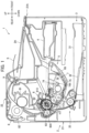
Fig. 1 is a diagram illustrating an image forming apparatus employing a process cartridge according to one embodiment. -
Fig. 2 is a diagram illustrating the image forming apparatus from which the process cartridge is detached. -
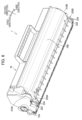
Fig. 3A is a perspective view of the process cartridge. -
Fig. 3B is a perspective view of a drum cartridge and a developing cartridge. -
Fig. 4 is a perspective view illustrating a locking lever, a first pressing member, and a second pressing member in the drum cartridge. -
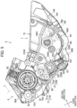
Fig. 5 is a cross-sectional view illustrating the first pressing member in the drum cartridge and a first pressure-receiving wall in the developing cartridge. -
Fig. 6 is a perspective view illustrating the first pressure-receiving wall and a second pressure-receiving wall in the developing cartridge. -
Fig. 7 is a cross-sectional view illustrating a state where the developing cartridge is lifted upward from the drum cartridge. -
Fig. 8 is an exploded perspective view illustrating one end portion of the developing cartridge. -
Fig. 9 is a cross-sectional perspective view illustrating one end portion of the process cartridge. -
Fig. 10 is a cross-sectional view illustrating the one end portion and another end portion of the process cartridge. - Hereinafter, one embodiment of the present invention will be described while referring to the accompanying drawings.
- As illustrated in
Fig. 1 , animage forming apparatus 1 includes ahousing 2, a sheet-feeding unit 3, anexposure unit 4, aprocess cartridge 5, and afixing unit 8. - The sheet-
feeding unit 3 is positioned at a lower portion inside thehousing 2. The sheet-feeding unit 3 includes asheet tray 31, alifter plate 32, and a sheet-feeding mechanism 33. Thesheet tray 31 is configured to accommodate therein sheets S of paper or the like. Thelifter plate 32 is configured to lift the sheets S accommodated in thesheet tray 31 upward. The sheet-feedingmechanism 33 is configured to feed the sheets S lifted upward by thelifter plate 32 toward theprocess cartridge 5. - The
exposure unit 4 is positioned upward of thesheet tray 31. Theexposure unit 4 includes a light source, a deflector, lenses, mirrors, and the like. Theexposure unit 4 is configured to emit a laser beam as indicated by a phantom line inFig. 1 in order to expose a surface of aphotosensitive drum 61 to light. - The
process cartridge 5 is positioned upward of the sheet-feedingmechanism 33. Theprocess cartridge 5 includes adrum cartridge 6, and a developingcartridge 7. - The
drum cartridge 6 includes thephotosensitive drum 61, acharger 62, atransfer roller 63, and adrum frame 65. Thephotosensitive drum 61 is rotatable about adrum axis 61X extending in the first direction. In the present embodiment, the first direction corresponds to a left-right direction of theimage forming apparatus 1. - The
charger 62 is configured to charge the surface of thephotosensitive drum 61. Thetransfer roller 63 is rotatable about a transfer-roller axis 63X extending in the first direction. Thedrum frame 65 holds thephotosensitive drum 61, thecharger 62, and thetransfer roller 63. - The developing
cartridge 7 includes a developingroller 71, asupply roller 72, a thickness-regulatingblade 73, anagitator 74, and a developingframe 75. - The developing
roller 71 is rotatable about a developing-roller axis 71X extending in the first direction. Thesupply roller 72 is rotatable about a supply-roller axis 72X extending in the first direction. The thickness-regulatingblade 73 is configured to regulate a layer of toner on the developingroller 71 so that the layer is formed to have a constant thickness. - The developing
frame 75 holds the developingroller 71, thesupply roller 72, the thickness-regulatingblade 73, and theagitator 74. The developingframe 75 is configured to accommodate therein toner. Specifically, the developingframe 75 has a toner-accommodatingportion 76 configured to accommodate therein toner. - The
agitator 74 is rotatable about anagitator axis 74X extending in the first direction. By rotating, theagitator 74 is configured to agitate toner in the toner-accommodatingportion 76. Thesupply roller 72 is configured to supply toner accommodated in the toner-accommodatingportion 76 to the developingroller 71. - The fixing
unit 8 is positioned upward of theprocess cartridge 5. The fixingunit 8 includes aheating roller 81, and apressure roller 82. Theheating roller 81 is configured to heat the sheets S. Thepressure roller 82 is configured to nip the sheets S at a position between thepressure roller 82 and theheating roller 81. - The
image forming apparatus 1 charges the surface of thephotosensitive drum 61 using thecharger 62. Theimage forming apparatus 1 subsequently exposes the charged surface of thephotosensitive drum 61 to light with a laser beam emitted from theexposure unit 4. As a result, an electrostatic latent image is formed on thephotosensitive drum 61 based on image data. Next, theimage forming apparatus 1 supplies toner from the developingroller 71 onto thephotosensitive drum 61, thereby forming a toner image on thephotosensitive drum 61. - The
image forming apparatus 1 subsequently conveys a sheet S supplied from the sheet-feedingunit 3 at a position between thephotosensitive drum 61 and thetransfer roller 63, whereby the toner image formed on thephotosensitive drum 61 is transferred onto the sheet S. Thereafter, theimage forming apparatus 1 conveys the sheet S on which the toner image has been transferred at a position between theheating roller 81 and thepressure roller 82. As a result, the toner image transferred onto the sheet S is fixed to the sheet S. - With a
discharge roller 9, theimage forming apparatus 1 discharges the sheet S on which the toner image has been fixed onto adischarge tray 2A. - The
housing 2 has ahousing body 21, and acover 22. Thehousing body 21 has anopening 21A. Thecover 22 is configured to open and close theopening 21A. Thecover 22 is movable relative to thehousing body 21 between a closed position illustrated inFig. 1 and an open position illustrated inFig. 2 . Specifically, thecover 22 is pivotally movable relative to thehousing body 21 between the closed position and the open position. In the closed position, thecover 22 closes theopening 21A. In the open position, thecover 22 opens theopening 21A. - As illustrated in
Fig. 2 , theprocess cartridge 5 is attachable to and detachable from thehousing 2. Specifically, theprocess cartridge 5 is attachable to and detachable from thehousing body 21 through theopening 21A in a state where thecover 22 is in the open position. - As illustrated in
Figs. 3A and 3B , the developingcartridge 7 is attachable to and detachable from thedrum cartridge 6.Fig. 3A illustrates theprocess cartridge 5 in which the developingcartridge 7 is attached to thedrum cartridge 6.Fig. 3B illustrates a state where the developingcartridge 7 is detached from thedrum cartridge 6. - Hereinafter, in the referenced drawings, arrows are used to indicate the first direction, a second direction, and a third direction. In these drawings, each arrow points to one side in the corresponding direction. Specifically, a leading side of each arrow represents one side in the corresponding direction, and a trailing side of each arrow represents the other side in the corresponding direction. The second direction is orthogonal to the first direction. The third direction is orthogonal to both the first direction and the second direction.
- As illustrated in
Fig. 4 , thedrum cartridge 6 further includes a lockinglever 140, a first pressingmember 150A, and a secondpressing member 150B. Thedrum frame 65 has a firstdrum end portion 65A, and a seconddrum end portion 65B. Each of the first pressingmember 150A and the second pressingmember 150B is an example of the "pressing member". - The first
drum end portion 65A is an end portion in the third direction of thedrum frame 65 that is close thephotosensitive drum 61. In other words, the firstdrum end portion 65A is another end portion in the third direction of thedrum frame 65. The seconddrum end portion 65B is an end portion in the third direction of thedrum frame 65 that is far from thephotosensitive drum 61. In other words, the seconddrum end portion 65B is one end portion in the third direction of thedrum frame 65. - The locking
lever 140 locks the developingcartridge 7 relative to thedrum cartridge 6 in a state where the developingcartridge 7 is attached to thedrum cartridge 6. The lockinglever 140 is positioned at another end in the first direction of thedrum frame 65. The lockinglever 140 is positioned closer to the seconddrum end portion 65B than thephotosensitive drum 61 is to the seconddrum end portion 65B in the third direction. - The first
pressing member 150A and the second pressingmember 150B press the developingcartridge 7 toward thephotosensitive drum 61 in the state where the developingcartridge 7 is attached to thedrum cartridge 6. As a result, the first pressingmember 150A and the second pressingmember 150B press the developingroller 71 against thephotosensitive drum 61. - The first
pressing member 150A is positioned at one end in the first direction of thedrum frame 65. The secondpressing member 150B is positioned at the other end in the first direction of thedrum frame 65. The firstpressing member 150A and the second pressingmember 150B are positioned closer to thephotosensitive drum 61 than the lockinglever 140 is to thephotosensitive drum 61 in the third direction. The firstpressing member 150A and the second pressingmember 150B have configurations that are symmetrical to each other in the first direction. - As illustrated in
Fig. 5 , the first pressingmember 150A includes apressing member body 151, and aspring 152. The secondpressing member 150B (seeFig. 10 ) similarly includes apressing member body 151, and aspring 152. - Each of the
pressing member bodies 151 is in contact with the developingcartridge 7 in the state where the developingcartridge 7 is attached to thedrum cartridge 6. Each of thepressing member bodies 151 is held by thedrum frame 65. Each of thepressing member bodies 151 is linearly movable along the third direction relative to thedrum frame 65. - Each of the
springs 152 is positioned between the corresponding pressingmember body 151 and the seconddrum end portion 65B of thedrum frame 65. Each of thesprings 152 urges the corresponding pressingmember body 151 toward the other side in the third direction. Each of thesprings 152 is a compression coil spring, for example. - As illustrated in
Figs. 5 and6 , the developingframe 75 includes a first pressure-receivingwall 220A, and a second pressure-receivingwall 220B. The developingframe 75 has a first developingend portion 75A, and a second developingend portion 75B. Each of the first pressure-receivingwall 220A and the second pressure-receivingwall 220B is an example of the "pressure-receiving wall". - The first developing
end portion 75A is an end portion in the third direction of the developingframe 75 that is close to thephotosensitive drum 61 in the state where the developingcartridge 7 is attached to thedrum cartridge 6. In other words, the first developingend portion 75A is another end portion in the third direction of the developingframe 75. - The second developing
end portion 75B is an end portion in the third direction of the developingframe 75 that is far from thephotosensitive drum 61 in the state where the developingcartridge 7 is attached to thedrum cartridge 6. In other words, the second developingend portion 75B is one end portion in the third direction of the developingframe 75. - In the state where the developing
cartridge 7 is attached to thedrum cartridge 6, the first pressure-receivingwall 220A is pressed by the first pressingmember 150A. The first pressure-receivingwall 220A is positioned at one end in the first direction of the developingframe 75. - In the state where the developing
cartridge 7 is attached to thedrum cartridge 6, the second pressure-receivingwall 220B is pressed by the second pressingmember 150B (seeFig. 10 ). The second pressure-receivingwall 220B is positioned at another end in the first direction of the developingframe 75. - As illustrated in
Fig. 5 , in the state where the developingcartridge 7 is attached to thedrum cartridge 6, the first pressure-receivingwall 220A is aligned with both thephotosensitive drum 61 and the developingroller 71 when viewed in the first direction. Specifically, in the state where the developingcartridge 7 is attached to thedrum cartridge 6, the first pressure-receivingwall 220A is positioned on a virtual straight line L when viewed in the first direction. The virtual straight line L passes through both thedrum axis 61X and the developing-roller axis 71X. The same is applied with respect to the second pressure-receivingwall 220B. - The developing
roller 71 includes a developingroller shaft 71A, and a developingroller body 71B. The developingroller shaft 71A extends in the first direction. The developingroller shaft 71A is made of metal, for example. The developingroller body 71B covers an outer circumferential surface of the developingroller shaft 71A. The developingroller body 71B is made of rubber, for example. - The
supply roller 72 includes asupply roller shaft 72A, and asupply roller body 72B. Thesupply roller shaft 72A extends in the first direction. Thesupply roller shaft 72A is made of metal, for example. Thesupply roller body 72B covers an outer circumferential surface of thesupply roller shaft 72A. Thesupply roller body 72B is made of sponge, for example. - In the state where the developing
cartridge 7 is attached to thedrum cartridge 6, thesupply roller 72 is aligned with both thephotosensitive drum 61 and the developingroller 71 when viewed in the first direction. Specifically, in the state where the developingcartridge 7 is attached to thedrum cartridge 6, thesupply roller shaft 72A is positioned on the virtual straight line L when viewed in the first direction. - The locking
lever 140 is movable relative to thedrum frame 65 between a locking position illustrated inFig. 5 , and a lock release position illustrated inFig. 7 . Specifically, the lockinglever 140 is pivotally movable relative to thedrum frame 65 between the locking position and the lock release position. - The locking
lever 140 includes ashaft portion 141, alock portion 142, apressing portion 143, and an operatingportion 144. - The
shaft portion 141 defines alever axis 140X about which the lockinglever 140 is pivotably movable. Thelever axis 140X extends in the first direction. Theshaft portion 141 is supported by thedrum frame 65 so as to be pivotally movable. - In a state where the locking
lever 140 is in the locking position illustrated inFig. 5 , thelock portion 142 locks the developingcartridge 7 relative to thedrum frame 65. In the state where the lockinglever 140 is in the locking position, thelock portion 142 extends toward the one side in the second direction from theshaft portion 141. Thelock portion 142 has arecess 142A into which aprotrusion 77 of the developingcartridge 7 is configured to be fitted. - The operating
portion 144 is a part that is configured to be operated by a user for moving the lockinglever 140 from the locking position to the lock release position. In the state where the lockinglever 140 is in the locking position, the operatingportion 144 extends diagonally toward the one side in the second direction and toward the one side in the third direction from thelock portion 142. - When the locking
lever 140 moves from the locking position to the lock release position, thepressing portion 143 contacts the developingcartridge 7 and presses the developingcartridge 7 upward. In the state where the lockinglever 140 is in the locking position, thepressing portion 143 extends toward the other side in the second direction from theshaft portion 141. - The locking
lever 140 is in the locking position in the state where the developingcartridge 7 is attached to thedrum cartridge 6. In this state, theprotrusion 77 of the developingcartridge 7 is positioned inside therecess 142A of thelock portion 142. As a result, the developingcartridge 7 is locked relative to thedrum cartridge 6. - When the locking
lever 140 moves from the locking position to the lock release position illustrated inFig. 7 , therecess 142A of thelock portion 142 disengages from theprotrusion 77 of the developingcartridge 7 and thepressing portion 143 presses the developingcartridge 7 upward. Accordingly, lock of the developingcartridge 7 relative to thedrum cartridge 6 is released, and the second developingend portion 75B of the developingcartridge 7 primarily separates from thedrum frame 65, whereby the developingcartridge 7 is detached from thedrum cartridge 6. - As illustrated in
Fig. 8 , the developingcartridge 7 further includes afirst seal 230A, and afirst bearing 240A. The developingframe 75 includes afirst side wall 210A. Thefirst seal 230A is an example of the "seal". Thefirst side wall 210A is an example of the "side wall". - The
first side wall 210A is positioned at the one end in the first direction of the developingframe 75. In the present embodiment, thefirst side wall 210A is orthogonal to the first direction. - The first pressure-receiving
wall 220A protrudes toward the one side in the first direction from thefirst side wall 210A. The first pressure-receivingwall 220A surrounds one end portion in the first direction of thesupply roller shaft 72A. Specifically, the first pressure-receivingwall 220A includes afirst wall 221, asecond wall 222, and athird wall 223. - Each of the
first wall 221 and thesecond wall 222 extends in the third direction. Thesecond wall 222 opposes thefirst wall 221 in the second direction. The one end portion in the first direction of thesupply roller shaft 72A is positioned between thefirst wall 221 and thesecond wall 222. Thefirst wall 221 is positioned on the one side of thesupply roller shaft 72A in the second direction. Thesecond wall 222 is positioned on the other side of thesupply roller shaft 72A in the second direction. - The
third wall 223 extends in the second direction. Thethird wall 223 connects one end of thefirst wall 221 and one end of thesecond wall 222 to each other. Specifically, thethird wall 223 connects one end in the third direction of thefirst wall 221 and one end in the third direction of thesecond wall 222 to each other. - The
third wall 223 protrudes further in the first direction than both thefirst wall 221 and thesecond wall 222. Specifically, a dimension in the first direction of thethird wall 223 is greater than a dimension in the first direction of thefirst wall 221 and is greater than a dimension in the first direction of thesecond wall 222. In the present embodiment, the dimension in the first direction of thefirst wall 221 and the dimension in the first direction of thesecond wall 222 are the same as each other. Thethird wall 223 directly opposes thesupply roller shaft 72A. - The first pressure-receiving
wall 220A also includesribs 224. Theribs 224 protrude toward the first pressingmember 150A (seeFig. 5 ) in the state where the developingcartridge 7 is attached to thedrum cartridge 6. Specifically, theribs 224 protrude toward the one side in the third direction from thethird wall 223. - The plurality of
ribs 224 are arranged in the first direction. In the present embodiment, two of theribs 224 are arranged in the first direction. Each of theribs 224 has an arc shape when viewed in the first direction. Specifically, one side surface in the third direction of each of theribs 224 has an arc shape when viewed in the first direction. - As illustrated in
Fig. 9 , thethird wall 223 of the first pressure-receivingwall 220A is pressed by the first pressingmember 150A in the state where the developingcartridge 7 is attached to thedrum cartridge 6. Specifically, theribs 224 of the first pressure-receivingwall 220A that protrude from thethird wall 223 are pressed by the first pressingmember 150A in the state where the developingcartridge 7 is attached to thedrum cartridge 6. - The
first seal 230A restricts toner from leaking through a gap between thesupply roller shaft 72A and the first pressure-receivingwall 220A. Thefirst seal 230A is positioned between thesupply roller shaft 72A and the first pressure-receivingwall 220A. The first pressure-receivingwall 220A holds thefirst seal 230A. Specifically, the first pressure-receivingwall 220A holds thefirst seal 230A at a position between the first wall 221 (seeFig. 5 ) and thesecond wall 222. - The
first seal 230A is mounted in the developingframe 75 together with thesupply roller 72 prior to mounting the developingroller 71 in the developingframe 75. Specifically, thefirst seal 230A is mounted in the developingframe 75 together with thesupply roller 72 while thesupply roller shaft 72A is inserted in a through-hole 231 (seeFig. 8 ) of thefirst seal 230A. Thefirst seal 230A is mounted in a portion inside the first pressure-receivingwall 220A from the first developingend portion 75A of the developingframe 75 toward the one side in the third direction. - Referring back to
Fig. 8 , thefirst bearing 240A supports the developingroller 71 and thesupply roller 72 so that the developingroller 71 and thesupply roller 72 are rotatable. Thefirst bearing 240A includes a first developingbearing 241A, and afirst supply bearing 242A. The first supply bearing 242A is an example of the "supply roller bearing". - The first developing bearing 241A supports the developing
roller 71 so that the developing roller71 is rotatable. One end portion in the first direction of the developingroller shaft 71A is fitted in the first developingbearing 241A. - The first supply bearing 242A supports the
supply roller 72 so that thesupply roller 72 is rotatable. The one end portion in the first direction of thesupply roller shaft 72A is fitted in thefirst supply bearing 242A. In the present embodiment, the first developing bearing 241A and thefirst supply bearing 242A are formed as a single member. - As illustrated in
Fig. 10 , thethird wall 223 of the first pressure-receivingwall 220A and the first supply bearing 242A are arranged in the third direction. Thethird wall 223 of the first pressure-receivingwall 220A is positioned on the one side of thefirst supply bearing 242A in the third direction. - The developing
cartridge 7 also includes asupply roller gear 72G. Thesupply roller gear 72G is rotatable together with thesupply roller 72 about the supply-roller axis 72X. Thesupply roller gear 72G is positioned at the one end portion in the first direction of thesupply roller shaft 72A. Thesupply roller gear 72G is fixed to thesupply roller shaft 72A. Thesupply roller 72 rotates upon input of a driving force into thesupply roller gear 72G. - The first pressure-receiving
wall 220A is positioned between thesupply roller gear 72G and thefirst side wall 210A of the developingframe 75. The first pressure-receivingwall 220A is positioned on the one side of thefirst side wall 210A in the first direction. The first pressure-receivingwall 220A is positioned on the other side of thesupply roller gear 72G in the first direction. - The first pressure-receiving
wall 220A and thesupply roller 72 are arranged in the first direction. The first pressure-receivingwall 220A is positioned on the one side of thesupply roller 72 in the first direction. Specifically, the first pressure-receivingwall 220A and thesupply roller body 72B are arranged in the first direction. The first pressure-receivingwall 220A is positioned on the one side of thesupply roller body 72B in the first direction. - The developing
cartridge 7 further includes asecond seal 230B, and asecond bearing 240B. The developingframe 75 further includes asecond side wall 210B. Thesecond seal 230B is also an example of the "seal". Thesecond side wall 210B is also an example of the "side wall". - The
second side wall 210B is positioned at the other end in the first direction of the developingframe 75. In the present embodiment, thesecond side wall 210B is orthogonal to the first direction. Thesecond side wall 210B opposes thefirst side wall 210A in the first direction. - The second pressure-receiving
wall 220B protrudes toward the other side in the first direction from thesecond side wall 210B. The second pressure-receivingwall 220B surrounds another end portion in the first direction of thesupply roller shaft 72A. The second pressure-receivingwall 220B has a configuration that is symmetrical to the first pressure-receivingwall 220A in the first direction. Specifically, as with the first pressure-receivingwall 220A, the second pressure-receivingwall 220B includes afirst wall 221, asecond wall 222, athird wall 223, andribs 224. Note that thefirst wall 221 and thesecond wall 222 of the second pressure-receivingwall 220B are omitted from the drawings. - The other end portion in the first direction of the
supply roller shaft 72A is positioned between thefirst wall 221 and the second wall 222 (which are not illustrated) of the second pressure-receivingwall 220B. Theribs 224 of the second pressure-receivingwall 220B protrude toward the second pressingmember 150B in the state where the developingcartridge 7 is attached to thedrum cartridge 6. - The
third wall 223 of the second pressure-receivingwall 220B is pressed by the second pressingmember 150B in the state where the developingcartridge 7 is attached to thedrum cartridge 6. Specifically, theribs 224 of the second pressure-receivingwall 220B are pressed by the second pressingmember 150B in the state where the developingcartridge 7 is attached to thedrum cartridge 6. - The
second seal 230B restricts toner from leaking through a gap between thesupply roller shaft 72A and the second pressure-receivingwall 220B. Thesecond seal 230B is positioned between thesupply roller shaft 72A and the second pressure-receivingwall 220B. The second pressure-receivingwall 220B holds thesecond seal 230B. Thesecond seal 230B is mounted in the developingframe 75 in the same manner as thefirst seal 230A. - The
second bearing 240B includes a second developing bearing 241B, and a second supply bearing 242B. The second supply bearing 242B is an example of the "supply roller bearing". - The second developing bearing 241B supports the developing
roller 71 so that the developingroller 71 is rotatable. Another end portion in the first direction of the developingroller shaft 71A is fitted in the second developing bearing 241B. - The second supply bearing 242B supports the
supply roller 72 so that thesupply roller 72 is rotatable. The other end portion in the first direction of thesupply roller shaft 72A is fitted in the second supply bearing 242B. In the present embodiment, the second developing bearing 241B and the second supply bearing 242B are formed as a single member. - The
third wall 223 of the second pressure-receivingwall 220B is juxtaposed with the second supply bearing 242B in the third direction. Thethird wall 223 of the second pressure-receivingwall 220B is positioned on the one side of the second supply bearing 242B in the third direction. - The second pressure-receiving
wall 220B is juxtaposed with thesupply roller 72 in the first direction. The second pressure-receivingwall 220B is positioned on the other side of thesupply roller 72 in the first direction. Specifically, the second pressure-receivingwall 220B is juxtaposed with thesupply roller body 72B in the first direction. The second pressure-receivingwall 220B is positioned on the other side of thesupply roller body 72B in the first direction. - Next, the advantageous effects according to the present embodiment will be described.
- By pressing the first pressure-receiving
wall 220A and the second pressure-receivingwall 220B, which surround the respective end portions in the first direction of thesupply roller shaft 72A, the first pressingmember 150A and the second pressingmember 150B can press the developingcartridge 7 toward thephotosensitive drum 61 at positions close to thephotosensitive drum 61. - Since a distance from the first pressure-receiving
wall 220A and the second pressure-receivingwall 220B to thephotosensitive drum 61 is short, thedrum frame 65 is less likely to be deformed due to a reaction force that the first pressingmember 150A and the second pressingmember 150B receive from the developingcartridge 7 in reaction to the pressing force of the first pressingmember 150A and the second pressingmember 150B. As a result, the loss of the pressing force caused by deformation of thedrum frame 65 can be reduced. - Reducing the loss of the pressing force allows the developing
cartridge 7 to be pressed toward thephotosensitive drum 61 with a small pressing force. In other words, the first pressingmember 150A and the second pressingmember 150B can press the developingcartridge 7 toward thephotosensitive drum 61 with a sufficient force, even if the urging force of thesprings 152 of the first pressingmember 150A and the second pressingmember 150B is small. - In the
process cartridge 5, the first pressure-receivingwall 220A and the second pressure-receivingwall 220B of the developingcartridge 7, which are pressed by the first pressingmember 150A and the second pressingmember 150B, respectively, are provided on the side walls in the first direction of the developingframe 75, rather than on the second developingend portion 75B of the developingframe 75. This arrangement allows the toner-accommodatingportion 76 of the developingframe 75 to be made larger toward the one side in the second direction and/or the one side in the third direction, thereby making it possible to increase the accommodating capacity of toner in the developingcartridge 7. - Since the
third walls 223, which are pressed by the first pressingmember 150A and the second pressingmember 150B, have a large dimension in the first direction, the developingcartridge 7 can be stably pressed toward thephotosensitive drum 61 when the first pressingmember 150A and the second pressingmember 150B press the respectivethird walls 223. - The developing
cartridge 7 includes thefirst seal 230A and thesecond seal 230B at positions between thesupply roller shaft 72A and the respective first pressure-receivingwall 220A and second pressure-receivingwall 220B. Thefirst seal 230A and thesecond seal 230B can retrain toner from leaking through gaps between thesupply roller shaft 72A and the respective first pressure-receivingwall 220A and second pressure-receivingwall 220B. The first pressure-receivingwall 220A and the second pressure-receivingwall 220B, which surround thesupply roller shaft 72A, can serve as the parts that hold thefirst seal 230A and thesecond seal 230B, respectively. - Since each of the first pressure-receiving
wall 220A and the second pressure-receivingwall 220B includes theribs 224, the first pressure-receivingwall 220A and the second pressure-receivingwall 220B, which receive a pressing force from the first pressingmember 150A and the second pressingmember 150B, respectively, can be reinforced. - Since each of the
ribs 224 has an arc shape, theribs 224 are unlikely to catch on the first pressingmember 150A and the second pressingmember 150B during attachment and detachment of the developingcartridge 7 to and from thedrum cartridge 6, thereby enabling the developingcartridge 7 to be easily attached to and detachable from thedrum cartridge 6. - The plurality of
ribs 224 is arranged in the first direction. Accordingly, the developingcartridge 7 can be pressed stably toward thephotosensitive drum 61 when theribs 224 are pressed by the first pressingmember 150A and the second pressingmember 150B. Also, the plurality ofribs 224 can better reinforce the first pressure-receivingwall 220A and the second pressure-receivingwall 220B. - By positioning the first pressure-receiving
wall 220A and the second pressure-receivingwall 220B on the virtual straight line L, which passes through both thedrum axis 61X and the developing-roller axis 71X, the developingroller 71 can be pressed toward thedrum axis 61X of thephotosensitive drum 61 when the first pressure-receivingwall 220A and the second pressure-receivingwall 220B are pressed by the first pressingmember 150A and the second pressingmember 150B, respectively. - Since the
third walls 223 of the first pressure-receivingwall 220A and the second pressure-receivingwall 220B are aligned with the first supply bearing 242A and the second supply bearing 242B, respectively, in the third direction, the developingcartridge 7 can be made more compact in the first direction in comparison with a configuration in which thethird walls 223 of the first pressure-receivingwall 220A and the second pressure-receivingwall 220B are offset from the respectivefirst supply bearing 242A and second supply bearing 242B in the first direction. As a result, thedrum cartridge 6 and theprocess cartridge 5 can be made more compact in the first direction. - While the invention has been described in conjunction with various example structures outlined above and illustrated in the figures, various alternatives, modifications, variations, improvements, and/or substantial equivalents, whether known or that may be presently unforeseen, may become apparent to those having at least ordinary skill in the art. Accordingly, the example embodiments of the disclosure, as set forth above, are intended to be illustrative of the invention, and not limiting the invention. Various changes may be made without departing from the spirit and scope of the disclosure. Therefore, the disclosure is intended to embrace all known or later developed alternatives, modifications, variations, improvements, and/or substantial equivalents. Some specific examples of potential alternatives, modifications, or variations in the described invention are provided below:
- Each of the
ribs 224 has an arc shape in the above-described embodiment. However, theribs 224 may have a trapezoidal shape or a rectangular shape, for example. - Although the first pressure-receiving
wall 220A is configured so that the first pressure-receivingwall 220A includes two of theribs 224 in the above embodiment, the first pressure-receivingwall 220A may be configured so that the first pressure-receivingwall 220A includes three ormore ribs 224, example. Alternatively, the first pressure-receivingwall 220A may be configured so that the first pressure-receivingwall 220A includes only onerib 224. Still alternatively, theribs 224 may be omitted from the first pressure-receivingwall 220A. The second pressure-receivingwall 220B may be similarly configured. - In the embodiment described above, the
third wall 223 has a dimension in the first direction that is greater than that of thefirst wall 221 and thesecond wall 222, but thethird wall 223 may have the same dimension in the first direction as at least one of thefirst wall 221 and thesecond wall 222, for example. In other words, at least one of thefirst wall 221 and thesecond wall 222 may have the same dimension in the first direction as thethird wall 223. Moreover, thefirst wall 221 and thesecond wall 222 may have dimensions in the first direction different from each other. - In the embodiment described above, the
third wall 223 of the first pressure-receivingwall 220A is positioned between thesupply roller gear 72G and thefirst side wall 210A so as to overlap thesupply roller gear 72G when viewed in the first direction. However, thethird wall 223 may be positioned so as not to overlap thesupply roller gear 72G when viewed in the first direction, for example. - In the embodiment described above, the first pressure-receiving
wall 220A is juxtaposed with thesupply roller 72 in the first direction so as to overlap thesupply roller 72 when viewed in the first direction. However, the first pressure-receivingwall 220A may be positioned so as not to overlap thesupply roller 72 when viewed in the first direction, for example. The same is applied with respect to the second pressure-receivingwall 220B. - In the embodiment described above, the first pressure-receiving
wall 220A is juxtaposed with thefirst supply bearing 242A in the third direction. However, the first pressure-receivingwall 220A may be disposed in a different position in the first direction from the first supply bearing 242A, for example. The same is applied with respect to the second pressure-receivingwall 220B and the second supply bearing 242B. - In the embodiment described above, the first pressure-receiving
wall 220A and the second pressure-receivingwall 220B are positioned on the virtual straight line L, but the first pressure-receivingwall 220A and the second pressure-receivingwall 220B need not be positioned on the virtual straight line L, for example. Similarly, thesupply roller shaft 72A need not be positioned on the virtual straight line L. - In the embodiment described above, the developing
cartridge 7 has the toner-accommodatingportion 76 configured to accommodate therein toner. However, the developingcartridge 7 may be configured without the toner-accommodatingportion 76, for example. In this case, a toner cartridge configured to accommodate therein toner may be attachable to and detachable from the developingcartridge 7 without the toner-accommodatingportion 76. In other words, theprocess cartridge 5 may be configured so that theprocess cartridge 5 includes thedrum cartridge 6, the developingcartridge 7, and the toner cartridge. - The elements appearing in the embodiment and modifications described above may be implemented in any suitable combination.
Claims (12)
- A process cartridge (5) comprising:a drum cartridge (6); anda developing cartridge (7) attachable to and detachable from the drum cartridge (6),the drum cartridge (6) including:a photosensitive drum (61) rotatable about a drum axis (61X) extending in a first direction; anda pressing member (150A, 150B) pressing the developing cartridge (7) toward the photosensitive drum (61) in a state where the developing cartridge (7) is attached to the drum cartridge (6),the developing cartridge (7) including:a developing roller (71) rotatable about a developing-roller axis (71X) extending in the first direction;a supply roller (72) rotatable about a supply-roller axis (72X) extending in the first direction, the supply roller (72) including a supply roller shaft (72A) extending in the first direction; anda developing frame (75) including:a side wall (210A, 210B) positioned at one end in the first direction of the developing frame (75); anda pressure-receiving wall (220A, 220B) protruding in the first direction from the side wall (210A, 210B), the pressure-receiving wall (220A, 220B) surrounding one end portion in the first direction of the supply roller shaft (72A),wherein, in the state where the developing cartridge (7) is attached to the drum cartridge (6), the pressure-receiving wall (220A, 220B) is pressed by the pressing member (150A, 150B).
- The process cartridge (5) according to claim 1,wherein the pressure-receiving wall (220A, 220B) includes:a first wall (221);a second wall (222) opposing the first wall (221) in a second direction orthogonal to the first direction; anda third wall (223) connecting one end of the first wall (221) and one end of the second wall (222) to each other,wherein the one end portion in the first direction of the supply roller shaft (72A) is positioned between the first wall (221) and the second wall (222), andwherein, in the state where the developing cartridge (7) is attached to the drum cartridge (6), the third wall (223) is pressed by the pressing member (150A, 150B).
- The process cartridge (5) according to claim 2,
wherein a dimension in the first direction of the third wall (223) is greater than a dimension in the first direction of the first wall (221) and is greater than a dimension in the first direction of the second wall (222). - The process cartridge (5) according to claim 1,wherein the developing frame (75) is configured to accommodate therein toner, andwherein the developing cartridge (7) further includes:
a seal (230A, 230B) positioned between the supply roller shaft (72A) and the pressure-receiving wall (220A, 220B). - The process cartridge (5) according to claim 1,
wherein the pressure-receiving wall (220A, 220B) includes:
a rib (224) protruding toward the pressing member (150A, 150B) and pressed by the pressing member (150A, 150B) in the state where the developing cartridge (7) is attached to the drum cartridge (6). - The process cartridge (5) according to claim 5,
wherein the rib (224) has an arc shape when viewed in the first direction. - The process cartridge (5) according to claim 5 or 6,
wherein a plurality of the ribs (224) is provided to be arranged in the first direction. - The process cartridge (5) according to claim 1,
wherein, in the state where the developing cartridge (7) is attached to the drum cartridge (6), the pressure-receiving wall (220A, 220B) is positioned on a virtual straight line (L) when viewed in the first direction, the virtual straight line (L) passing through both the drum axis (61X) and the developing-roller axis (71X). - The process cartridge (5) according to claim 2 or 3, further comprising:a supply roller bearing (242A, 242B) in which the supply roller shaft (72A) is fitted,wherein the supply roller bearing (242A, 242B) and the third wall (223) are arranged in a direction orthogonal to both the first direction and the second direction.
- The process cartridge (5) according to claim 1,
wherein the pressure-receiving wall (220A, 220B) and the supply roller (72) are arranged in the first direction. - The process cartridge (5) according to claim 1, further comprising:a supply roller gear (72G) positioned at the one end portion in the first direction of the supply roller shaft (72A), the supply roller gear (72G) being rotatable about the supply-roller axis (72X) together with the supply roller (72),wherein the pressure-receiving wall (220A) is positioned between the supply roller gear (72G) and the side wall (210A).
- The process cartridge (5) according to claim 1,
wherein, in the state where the developing cartridge (7) is attached to the drum cartridge (6), the supply roller shaft (72A) is positioned on a virtual straight line (L) when viewed in the first direction, the virtual straight line (L) passing through both the drum axis (61X) and the developing-roller axis (71X).
Applications Claiming Priority (1)
| Application Number | Priority Date | Filing Date | Title |
|---|---|---|---|
| JP2023179011A JP2025068902A (en) | 2023-10-17 | 2023-10-17 | Process cartridge |
Publications (1)
| Publication Number | Publication Date |
|---|---|
| EP4542308A1 true EP4542308A1 (en) | 2025-04-23 |
Family
ID=93119505
Family Applications (1)
| Application Number | Title | Priority Date | Filing Date |
|---|---|---|---|
| EP24206368.3A Pending EP4542308A1 (en) | 2023-10-17 | 2024-10-14 | Process cartridge |
Country Status (3)
| Country | Link |
|---|---|
| EP (1) | EP4542308A1 (en) |
| JP (1) | JP2025068902A (en) |
| CN (1) | CN119846921A (en) |
Citations (3)
| Publication number | Priority date | Publication date | Assignee | Title |
|---|---|---|---|---|
| US6519431B1 (en) * | 1999-05-20 | 2003-02-11 | Canon Kabushiki Kaisha | Process cartridge, assembling method therefor and electrophotographic image forming apparatus |
| US20090092413A1 (en) * | 1999-02-26 | 2009-04-09 | Brother Kogyo Kabushiki Kaisha | Photosensitive member cartridge |
| JP2014016480A (en) | 2012-07-09 | 2014-01-30 | Brother Ind Ltd | Image forming apparatus |
-
2023
- 2023-10-17 JP JP2023179011A patent/JP2025068902A/en active Pending
-
2024
- 2024-09-23 CN CN202411322565.1A patent/CN119846921A/en active Pending
- 2024-10-14 EP EP24206368.3A patent/EP4542308A1/en active Pending
Patent Citations (3)
| Publication number | Priority date | Publication date | Assignee | Title |
|---|---|---|---|---|
| US20090092413A1 (en) * | 1999-02-26 | 2009-04-09 | Brother Kogyo Kabushiki Kaisha | Photosensitive member cartridge |
| US6519431B1 (en) * | 1999-05-20 | 2003-02-11 | Canon Kabushiki Kaisha | Process cartridge, assembling method therefor and electrophotographic image forming apparatus |
| JP2014016480A (en) | 2012-07-09 | 2014-01-30 | Brother Ind Ltd | Image forming apparatus |
Also Published As
| Publication number | Publication date |
|---|---|
| JP2025068902A (en) | 2025-04-30 |
| CN119846921A (en) | 2025-04-18 |
Similar Documents
| Publication | Publication Date | Title |
|---|---|---|
| CN112650035B (en) | Toner cartridge, toner supply mechanism, and shutter | |
| US8688003B2 (en) | Process cartridge and electrophotographic image forming apparatus | |
| US6101350A (en) | Photosensitive member cartridge and developer cartridge for use in an image-forming apparatus | |
| EP1722279B1 (en) | Process cartridge with attachable toner cartridge exerting a pressure to urge the developing roller towards the image carrier | |
| US9250606B2 (en) | Drum unit | |
| JP2008185827A (en) | Developing device and toner cartridge | |
| JP7516961B2 (en) | Image forming device | |
| US20260010116A1 (en) | Image-forming apparatus including operating member disposed on movable cover for opening and closing shutter of toner container | |
| US12529983B2 (en) | Image forming apparatus including main body casing, fixing device attachable thereto, and spring configured to press boss of fixing device in attached state to main body casing | |
| JP7806580B2 (en) | Fixing device and image forming apparatus | |
| JP2025068902A (en) | Process cartridge | |
| EP4538802A1 (en) | Process cartridge | |
| JP2020052356A (en) | Image forming apparatus | |
| US20260016786A1 (en) | Image-forming apparatus including developing unit and drum unit to which toner container is connectable, and process unit configured by the drum unit and developing unit | |
| JP7276014B2 (en) | image forming device | |
| JP6887789B2 (en) | Image forming device | |
| JP2025027653A (en) | Image forming device | |
| JP2025184006A (en) | Fixing device | |
| HK40044716B (en) | Toner cartridge, toner supply mechanism, and shutter | |
| HK40044718B (en) | Toner cartridge, toner supply mechanism, and shutter | |
| HK40044719B (en) | Toner cartridge, toner supply mechanism, and shutter | |
| CN110068995A (en) | Imaging device | |
| HK40044719A (en) | Toner cartridge, toner supply mechanism, and shutter | |
| HK40044716A (en) | Toner cartridge, toner supply mechanism, and shutter | |
| HK40044717A (en) | Toner cartridge, toner supply mechanism, and shutter |
Legal Events
| Date | Code | Title | Description |
|---|---|---|---|
| PUAI | Public reference made under article 153(3) epc to a published international application that has entered the european phase |
Free format text: ORIGINAL CODE: 0009012 |
|
| STAA | Information on the status of an ep patent application or granted ep patent |
Free format text: STATUS: THE APPLICATION HAS BEEN PUBLISHED |
|
| AK | Designated contracting states |
Kind code of ref document: A1 Designated state(s): AL AT BE BG CH CY CZ DE DK EE ES FI FR GB GR HR HU IE IS IT LI LT LU LV MC ME MK MT NL NO PL PT RO RS SE SI SK SM TR |
|
| P01 | Opt-out of the competence of the unified patent court (upc) registered |
Free format text: CASE NUMBER: APP_19729/2025 Effective date: 20250424 |
|
| STAA | Information on the status of an ep patent application or granted ep patent |
Free format text: STATUS: REQUEST FOR EXAMINATION WAS MADE |
|
| 17P | Request for examination filed |
Effective date: 20250926 |