EP4542210A1 - Liquid intrusion detection device, liquid intrusion detection method and computer system thereof - Google Patents
Liquid intrusion detection device, liquid intrusion detection method and computer system thereof Download PDFInfo
- Publication number
- EP4542210A1 EP4542210A1 EP24201132.8A EP24201132A EP4542210A1 EP 4542210 A1 EP4542210 A1 EP 4542210A1 EP 24201132 A EP24201132 A EP 24201132A EP 4542210 A1 EP4542210 A1 EP 4542210A1
- Authority
- EP
- European Patent Office
- Prior art keywords
- detection
- signal
- liquid
- multiplexer
- output
- Prior art date
- Legal status (The legal status is an assumption and is not a legal conclusion. Google has not performed a legal analysis and makes no representation as to the accuracy of the status listed.)
- Pending
Links
Images


Classifications
-
- H—ELECTRICITY
- H02—GENERATION; CONVERSION OR DISTRIBUTION OF ELECTRIC POWER
- H02H—EMERGENCY PROTECTIVE CIRCUIT ARRANGEMENTS
- H02H5/00—Emergency protective circuit arrangements for automatic disconnection directly responsive to an undesired change from normal non-electric working conditions with or without subsequent reconnection
- H02H5/08—Emergency protective circuit arrangements for automatic disconnection directly responsive to an undesired change from normal non-electric working conditions with or without subsequent reconnection responsive to abnormal fluid pressure, liquid level or liquid displacement, e.g. Buchholz relays
- H02H5/083—Emergency protective circuit arrangements for automatic disconnection directly responsive to an undesired change from normal non-electric working conditions with or without subsequent reconnection responsive to abnormal fluid pressure, liquid level or liquid displacement, e.g. Buchholz relays responsive to the entry or leakage of a liquid into an electrical appliance
-
- G—PHYSICS
- G01—MEASURING; TESTING
- G01M—TESTING STATIC OR DYNAMIC BALANCE OF MACHINES OR STRUCTURES; TESTING OF STRUCTURES OR APPARATUS, NOT OTHERWISE PROVIDED FOR
- G01M3/00—Investigating fluid-tightness of structures
- G01M3/02—Investigating fluid-tightness of structures by using fluid or vacuum
-
- G—PHYSICS
- G01—MEASURING; TESTING
- G01D—MEASURING NOT SPECIALLY ADAPTED FOR A SPECIFIC VARIABLE; ARRANGEMENTS FOR MEASURING TWO OR MORE VARIABLES NOT COVERED IN A SINGLE OTHER SUBCLASS; TARIFF METERING APPARATUS; MEASURING OR TESTING NOT OTHERWISE PROVIDED FOR
- G01D21/00—Measuring or testing not otherwise provided for
-
- G—PHYSICS
- G01—MEASURING; TESTING
- G01D—MEASURING NOT SPECIALLY ADAPTED FOR A SPECIFIC VARIABLE; ARRANGEMENTS FOR MEASURING TWO OR MORE VARIABLES NOT COVERED IN A SINGLE OTHER SUBCLASS; TARIFF METERING APPARATUS; MEASURING OR TESTING NOT OTHERWISE PROVIDED FOR
- G01D21/00—Measuring or testing not otherwise provided for
- G01D21/02—Measuring two or more variables by means not covered by a single other subclass
-
- G—PHYSICS
- G01—MEASURING; TESTING
- G01M—TESTING STATIC OR DYNAMIC BALANCE OF MACHINES OR STRUCTURES; TESTING OF STRUCTURES OR APPARATUS, NOT OTHERWISE PROVIDED FOR
- G01M3/00—Investigating fluid-tightness of structures
- G01M3/02—Investigating fluid-tightness of structures by using fluid or vacuum
- G01M3/04—Investigating fluid-tightness of structures by using fluid or vacuum by detecting the presence of fluid at the leakage point
-
- G—PHYSICS
- G01—MEASURING; TESTING
- G01N—INVESTIGATING OR ANALYSING MATERIALS BY DETERMINING THEIR CHEMICAL OR PHYSICAL PROPERTIES
- G01N33/00—Investigating or analysing materials by specific methods not covered by groups G01N1/00 - G01N31/00
-
- G—PHYSICS
- G01—MEASURING; TESTING
- G01R—MEASURING ELECTRIC VARIABLES; MEASURING MAGNETIC VARIABLES
- G01R31/00—Arrangements for testing electric properties; Arrangements for locating electric faults; Arrangements for electrical testing characterised by what is being tested not provided for elsewhere
- G01R31/50—Testing of electric apparatus, lines, cables or components for short-circuits, continuity, leakage current or incorrect line connections
- G01R31/66—Testing of connections, e.g. of plugs or non-disconnectable joints
-
- G—PHYSICS
- G08—SIGNALLING
- G08B—SIGNALLING SYSTEMS, e.g. PERSONAL CALLING SYSTEMS; ORDER TELEGRAPHS; ALARM SYSTEMS
- G08B21/00—Alarms responsive to a single specified undesired or abnormal condition and not otherwise provided for
- G08B21/18—Status alarms
- G08B21/20—Status alarms responsive to moisture
-
- G—PHYSICS
- G01—MEASURING; TESTING
- G01M—TESTING STATIC OR DYNAMIC BALANCE OF MACHINES OR STRUCTURES; TESTING OF STRUCTURES OR APPARATUS, NOT OTHERWISE PROVIDED FOR
- G01M3/00—Investigating fluid-tightness of structures
- G01M3/40—Investigating fluid-tightness of structures by using electric means, e.g. by observing electric discharges
-
- G—PHYSICS
- G01—MEASURING; TESTING
- G01N—INVESTIGATING OR ANALYSING MATERIALS BY DETERMINING THEIR CHEMICAL OR PHYSICAL PROPERTIES
- G01N27/00—Investigating or analysing materials by the use of electric, electrochemical, or magnetic means
- G01N27/02—Investigating or analysing materials by the use of electric, electrochemical, or magnetic means by investigating impedance
- G01N27/04—Investigating or analysing materials by the use of electric, electrochemical, or magnetic means by investigating impedance by investigating resistance
- G01N27/048—Investigating or analysing materials by the use of electric, electrochemical, or magnetic means by investigating impedance by investigating resistance for determining moisture content of the material
Definitions
- This disclosure relates to a liquid intrusion detection device, liquid intrusion detection method and computer system thereof.
- the test specifications and the humidity test standards are the same.
- moisture may enter the system and circuit board during the humidity test, and the only way to reduce moisture expose is by attaching mylar to the circuit board. Therefore, the current problem in this field is to find a solution to detect whether moisture has entered the circuit board and may have caused damage to some chips, and to provide timely notification so that the microcontroller/central processor and other computing components of the system can take corresponding action.
- this disclosure provides a liquid intrusion detection device, liquid intrusion detection method and computer system thereof.
- a liquid intrusion detection device comprises at least one circuit board, a plurality of liquid detection components, a multiplexer and a computing component.
- the plurality of liquid detection components are disposed on the at least one circuit board.
- the multiplexer is disposed on the at least one circuit board and has a plurality of output pins respectively connected to the plurality of liquid detection components.
- the computing component is disposed on the at least one circuit board and connected to the multiplexer, and is configured to switch the multiplexer to output a detection signal to one of the plurality of liquid detection components through one of the plurality of output pins, and output a liquid intrusion notification signal when a response signal of the detection signal meets a preset potential.
- a liquid intrusion detection method comprises: providing a liquid intrusion detection device, wherein the liquid intrusion detection device comprises at least one circuit board and a plurality of liquid detection components, a multiplexer and a computing component disposed on the at least one circuit board; and executing with the computing component: switching the multiplexer to output a detection signal to one of the plurality of liquid detection components; detecting a response signal of the detection signal; and outputting a liquid intrusion notification signal when a response signal of the detection signal meets a preset potential.
- a computer system comprises a power switch and a liquid intrusion detection device as described above.
- the liquid intrusion detection device is connected to the power switch, wherein the computing component outputs the liquid intrusion notification signal to the power switch to turn off all the power switch.
- the liquid intrusion detection device, liquid intrusion detection method and computer system thereof of the present disclosure by disposing multiple liquid detection components on one or more circuit boards, may perform water vapor/humidity detection on any selected area of the circuit board without the need to install additional detection components on the circuit board, and may reduce the costs.
- the computing component By using the computing component to switch each pin of the multiplexer, the response signal of the specific liquid detection component may be obtained and a liquid intrusion notification may be issued when it is determined that liquid intrusion has occurred.
- one computing component and multiple liquid detection components may be integrated through a multiplexer, without the need for additional computing components such as multiple microcontrollers/central processors.
- liquid intrusion detection device liquid intrusion detection method and computer system thereof described herein may be applied to electronic devices or equipment that are sensitive to liquid, humidity or moisture, but the present disclosure is not limited thereto.
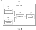
- FIG. 1 is a block diagram of a liquid intrusion detection device according to an embodiment of the present disclosure.
- a liquid intrusion detection device 10 comprises at least one circuit board 100, a plurality of liquid detection components 101a and 101b, a multiplexer 102 and a computing component 103.
- the plurality of liquid detection components 101a and 101b are disposed on the at least one circuit board 100.
- the multiplexer 102 is disposed on the at least one circuit board 100 and has a plurality of output pins respectively connected to the plurality of liquid detection components 101a and 101b.
- the computing component 103 is disposed on the at least one circuit board 100 and connected to the multiplexer 102, and is configured to switch the multiplexer 102 to output a detection signal to one of the plurality of liquid detection components 101a and 101b through one of the plurality of output pins, and output a liquid intrusion notification signal when a response signal of the detection signal meets a preset potential.
- the circuit board 100 of the liquid intrusion detection device 10 may be an existing circuit board of the system, that is, the liquid intrusion detection device 10 may be integrated with the circuit board of any device (such as a personal computer).
- the liquid detection components 101a and 101b are disposed on the circuit board 100, and are preferably integrated with the circuit board 100 through PCB layout. The number and position of the liquid detection components 101a and 101b may be adjusted according to application requirements.
- the liquid detection components 101a and 101b may be disposed at each corner of the circuit board 100 to maximize the detection range for liquid intrusion; or, the liquid detection components 101a and 101b may be disposed around a specific chip to ensure that the specific chip is protected from the influence of moisture; or, the liquid detection components 101a and 101b may be disposed adjacent to connectors, such as connection ports, screw holes, etc., so as to be triggered as soon as the liquid intrusion occurs and generate a notification signal.
- the multiplexer 102 may select one of a plurality of input signals for output.
- the computing component 103 may be implemented through a microcontroller, a central processing unit (CPU) or a programmable logic controller (PLC).
- the computing component 103 is connected to the plurality of liquid detection components 101a and 101b through the multiplexer 102 to obtain response signals of each liquid detection components 101a and 101b, and output a liquid intrusion notification signal when determining that the potential of the response signal reaches a preset potential.
- the computing component 103 may periodically switch a plurality of output pins of the multiplexer 102 to output a detection signal to one of the plurality of liquid detection components 101a and 101b through one of the plurality of output pins, and when a response signal of the detection signal meets a preset potential, the computing component 103 may output a liquid intrusion notification signal to provide immediate notification of potential liquid intrusion.
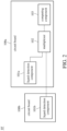
- FIG. 2 is a block diagram of a liquid intrusion detection device according to another embodiment of the present disclosure.
- the liquid detection components 101a and 101b of the liquid intrusion detection device 10' in the present embodiment are respectively disposed on two circuit boards 100a and 100b, wherein the two circuit boards 100a and 100b may be connected to each other through a flexible PCB (FPCB), a cable or a board-to-board connector.
- the liquid detection component 101b may be electrically connected to the multiplexer 102 on another circuit board 100a through the connection method described above.
- other descriptions about the operations of the multiplexer 102 and the computing component 103 are basically the same as those in the embodiment of FIG. 1 and are omitted herein.
- FIG. 3A is a schematic diagram of the pin connections between the multiplexer and the computing component of the liquid intrusion detection device according to an embodiment of the present disclosure.
- the computing component 103 has a switching signal output pin 1031 and a detection pin 1032 that are connected to the multiplexer 102.
- the switching signal output pin 1031 is configured to output a switching signal to the multiplexer 102
- the detection pin 1032 is configured to output the detection signal and detect the response signal.
- the computing component 103 in the present embodiment may transmit a switching signal to the multiplexer 102 through the switching signal output pin 1031, and output the detection signal to the multiplexer 102 through the detection pin 1032, wherein the switching signal specifies one of the plurality of liquid detection components.
- the multiplexer 102 may output the received detection signal to the specified liquid detection component through the corresponding output pin, and then obtain the response signal of the specified liquid detection component.
- the computing component 103 may obtain the response signal through the detection pin 1032, that is, obtain a liquid detection result of the specific liquid detection component. Therefore, in the present embodiment, the pin for outputting the detection signal and the pin for receiving the response signal of the computing component 103 are the same pin (detection pin 1032).
- FIG. 3B is a schematic diagram of the pin connections between the multiplexer and the computing component of the liquid intrusion detection device according to another embodiment of the present disclosure.
- the computing component 103' has a switching signal output pin 1031, a detection signal output pin 1033 and a response signal input pin 1034 that are connected to the multiplexer 102.
- the switching signal output pin 1031 is configured to output a switching signal to the multiplexer 102
- the detection signal output pin 1033 is configured to output the detection signal
- the response signal input pin 1034 is connected to the detection signal output pin 1033 to detect the response signal.
- the computing component 103' in the present embodiment may transmit a switching signal to the multiplexer 102 through the switching signal output pin 1031, and output the detection signal to the multiplexer 102 through the detection signal output pin 1033, wherein the switching signal corresponds to the plurality of liquid detection components.
- the multiplexer 102 may output the received detection signal to a specified liquid detection component through the corresponding output pin, and then obtain the response signal of the specified liquid detection component.
- the computing component 103 may obtain the response signal through the response signal input pin 1034, that is, obtain a liquid detection result of the specified liquid detection component.
- the multiplexer 102 obtains the detection signal of the computing component 103' and transmits the response signal to the computing component 103' through one pin
- the computing component 103' outputs the detection signal (through detection signal output pin 1033) and obtains a response signal (through response signal input pin 1034) through different pins.
- FIG. 4 is a schematic diagram of the liquid detection component of the liquid intrusion detection device according to an embodiment of the present disclosure.
- one of the plurality of liquid detection components 101 comprises a first comb-shape electrode 1011 and a second comb-shape electrode 1012 that are disposed correspondingly, wherein the first comb-shape electrode 1011 is connected to the multiplexer and is configured to receive an operating voltage VCC, and the second comb-shape electrode 1012 is configured to be connected to the ground terminal GND.
- the first comb-shape electrode 1011 and the second comb-shape electrode 1012 may be formed on the circuit board of the liquid intrusion detection device.
- the first comb-shape electrode 1011 is connected to an operating voltage VCC through a resistor R1, wherein the operating voltage VCC may be, for example, 3.3 volts, and the first comb-shape electrode 1011 is connected to one end T1 and connected to the multiplexer through the one end T1.
- the second comb-shape electrode 1012 is grounded and is electrically isolated from the first comb-shape electrode 1011 when there is no moisture around. When there is moisture around and the moisture is condensed into tiny droplets, the second comb-shape electrode 1012 and the first comb-shape electrode 1011 have a certain degree of electrical conduction.
- the multiplexer may obtain a response signal with a corresponding voltage value through the one terminal T1 and transmit the response signal back to the computing component. If the voltage value of the response signal is close to the operating voltage VCC, the computing component determines that the first comb-shape electrode 1011 and the second comb-shape electrode 1012 are electrically isolated from each other; if the voltage value of the response signal is lower than the operating voltage VCC to a certain extent, then the computing component determines that the first comb-shape electrode 1011 and the second comb-shape electrode 1012 are electrically connected to each other, and outputs a liquid intrusion notification signal.
- the detection signal output by the computing component through the output pin by switching the multiplexer may be a pulse-width modulation (PWM) signal, to reduce the power consumption of computing component when performing detection.
- PWM pulse-width modulation
- the computing component determines that the first comb-shape electrode 1011 and the second comb-shape electrode 1012 are electrically isolated from each other; if the voltage value of the response signal is lower than the operating voltage VCC to a certain extent, the computing component determines that the first comb-shape electrode 1011 and the second comb-shape electrode 1012 are electrically connected to each other, and outputs a liquid intrusion notification signal.
- FIG. 5 is a block diagram of a computer system according to an embodiment of the present disclosure.
- the computer system 1 comprises a liquid intrusion detection device 10 and a power switch 20.
- the liquid intrusion detection device 10 comprises at least one circuit board 100, a plurality of liquid detection components 101a and 101b, a multiplexer 102 and a computing component 103.
- the plurality of liquid detection components 101a and 101b are disposed on the at least one circuit board 100.
- the multiplexer 102 is disposed on the at least one circuit board 100 and has a plurality of output pins respectively connected to a plurality of liquid detection components 101a and 101b.
- the computing component 103 is disposed on the at least one circuit board 100 and connected to the multiplexer 102, and is configured to switch the multiplexer 102 to output a detection signal to one of the plurality of liquid detection components 101a and 101b through one of the plurality of output pins, and output a liquid intrusion notification signal when a response signal of the detection signal meets a preset potential.
- the liquid intrusion detection device 10 is connected to the power switch 20, wherein the computing component 103 outputs the liquid intrusion notification signal to the power switch 20 to turn off the power switch 20.
- the liquid intrusion detection device 10 of the present embodiment is basically the same as the liquid intrusion detection device 10 of the embodiment shown in FIG. 1 , and may be combined with the embodiments described above, and repeated descriptions are omitted herein.
- the computing component 103 of the liquid intrusion detection device 10 is specifically connected to a power switch 20, where the power switch 20 may be used to control the power supply of the system.
- the computing component 103 may output a liquid intrusion notification signal to the power switch 20 and control the power switch 20 to be turn off to avoid damage caused by liquid intrusion.
- the power switch 20 may be formed by using an N-type transistor (N MOSFET) or a P-type transistor (P MOSFET) or a combined power switch integrated chip, or a circuit with a power switching function formed by the N-type transistor and P-type transistor described above alone or in combination.
- the power switch 20 may be a power switch chip with a model number of XC8107AC20ER-G, or may be a switching circuit designed by using a P-type transistor with a model number of MDV3604 and an N-type transistor with a model number of L2N7002WT1G.
- other types of switch circuits with power-off or isolation circuit designs may also be used to achieve the above effects.
- a liquid intrusion detection method comprises: step S11: providing a liquid intrusion detection device, wherein the liquid intrusion detection device comprises at least one circuit board and a plurality of liquid detection components, a multiplexer and a computing component that are disposed on the at least one circuit board; and executing with the computing component: step S12: switching the multiplexer to output a detection signal to one of the plurality of liquid detection components; step S 13: detecting a response signal of the detection signal; and step S14: outputting a liquid intrusion notification signal when a response signal of the detection signal meets a preset potential.
- the provided liquid intrusion detection device may refer to the liquid intrusion detection device in the embodiment of FIGs. 1 to 5 .
- the computing component 103 may switch the multiplexer 102 to output the detection signal to one of the liquid detection components 101a and 101b by switching the signal output pin 1031.
- the computing component 103 may detect the voltage level of the response signal to determine whether liquid intrusion occurs near the corresponding liquid detection component.
- the computing component 103 may output a liquid intrusion notification signal.
- FIG. 7 is a flow chart of a liquid intrusion detection method according to another embodiment of the present disclosure.
- the liquid intrusion detection method of the present embodiment may further execute with the computing component: step S21: switching the multiplexer to output a detection signal to one of the plurality of liquid detection components; step S22: detecting a response signal of the detection signal; step S23: determining whether the response signal meets the preset potential; if the determination result is "yes”, execute step S24: outputting a liquid intrusion notification signal; if the determination result is "no”, execute step S25: switching the multiplexer to output the detection signal to another one of the plurality of liquid detection components.
- Steps S21 and S22 in the present embodiment are basically the same as steps S12 and S13 shown in FIG. 6 , and repeated descriptions are omitted herein.
- the computing component 103 may determine whether the response signal meets a preset potential, wherein the preset potential may correspond to a specific proportional value of the operating voltage VCC.
- the computing component 103 may output a liquid intrusion signal.
- step S25 when the computing component 103 determines that the response signal does not meet the preset potential (not lower than the operating voltage VCC to a certain extent), the computing component 103 may switch the multiplexer 102 to output the detection signal to another one of the plurality of liquid detection components, that is, re-executes step S22 on another liquid detection component.
- the liquid intrusion detection device, liquid intrusion detection method and computer system thereof of the present disclosure by disposing multiple liquid detection components on one or more circuit boards, may perform water vapor/humidity detection on any selected area of the circuit board without the need to install additional detection components on the circuit board, and may reduce the costs.
- the computing component By using the computing component to switch each pin of the multiplexer, the response signal of the specific liquid detection component may be obtained and a liquid intrusion notification may be issued when it is determined that liquid intrusion has occurred.
- one computing component and multiple liquid detection components may be integrated through a multiplexer, without the need for additional computing components such as multiple microcontrollers/central processors.
- pulse width modulation as the detection signal of the computing component, the power consumption of the computing component when performing detection may be reduced.
Landscapes
- Physics & Mathematics (AREA)
- General Physics & Mathematics (AREA)
- Chemical & Material Sciences (AREA)
- Life Sciences & Earth Sciences (AREA)
- Health & Medical Sciences (AREA)
- Pathology (AREA)
- Immunology (AREA)
- Analytical Chemistry (AREA)
- Biochemistry (AREA)
- General Health & Medical Sciences (AREA)
- Chemical Kinetics & Catalysis (AREA)
- Business, Economics & Management (AREA)
- Emergency Management (AREA)
- Electrochemistry (AREA)
- Food Science & Technology (AREA)
- Engineering & Computer Science (AREA)
- Medicinal Chemistry (AREA)
- Fluid Mechanics (AREA)
- Burglar Alarm Systems (AREA)
Abstract
A liquid intrusion detection device (10) comprises at least one circuit board (100), a plurality of liquid detection components (101a, 101b), a multiplexer (102) and a computing component (103). The plurality of liquid detection components (101a, 101b) are disposed on the at least one circuit board (100). The multiplexer (102) is disposed on the at least one circuit board (100) and has a plurality of output pins respectively connected to the plurality of liquid detection components (101a, 101b). The computing component (103) is disposed on the at least one circuit board (100) and connected to the multiplexer (102), and is configured to switch the multiplexer (102) to output a detection signal to one of the plurality of liquid detection components (101a, 101b) through one of the plurality of output pins, and output a liquid intrusion notification signal when a response signal of the detection signal meets a preset potential.
Description
- This disclosure relates to a liquid intrusion detection device, liquid intrusion detection method and computer system thereof.
- Currently, for the semi-rugged computers and the fully-rugged computers, the test specifications and the humidity test standards are the same. However, due to the lack of an airtight design in semi-rugged computers, moisture may enter the system and circuit board during the humidity test, and the only way to reduce moisture expose is by attaching mylar to the circuit board. Therefore, the current problem in this field is to find a solution to detect whether moisture has entered the circuit board and may have caused damage to some chips, and to provide timely notification so that the microcontroller/central processor and other computing components of the system can take corresponding action.
- Accordingly, this disclosure provides a liquid intrusion detection device, liquid intrusion detection method and computer system thereof.
- According to one or more embodiments of this disclosure, a liquid intrusion detection device comprises at least one circuit board, a plurality of liquid detection components, a multiplexer and a computing component. The plurality of liquid detection components are disposed on the at least one circuit board. The multiplexer is disposed on the at least one circuit board and has a plurality of output pins respectively connected to the plurality of liquid detection components. The computing component is disposed on the at least one circuit board and connected to the multiplexer, and is configured to switch the multiplexer to output a detection signal to one of the plurality of liquid detection components through one of the plurality of output pins, and output a liquid intrusion notification signal when a response signal of the detection signal meets a preset potential.
- According to one or more embodiments of this disclosure, a liquid intrusion detection method comprises: providing a liquid intrusion detection device, wherein the liquid intrusion detection device comprises at least one circuit board and a plurality of liquid detection components, a multiplexer and a computing component disposed on the at least one circuit board; and executing with the computing component: switching the multiplexer to output a detection signal to one of the plurality of liquid detection components; detecting a response signal of the detection signal; and outputting a liquid intrusion notification signal when a response signal of the detection signal meets a preset potential.
- According to one or more embodiments of this disclosure, a computer system comprises a power switch and a liquid intrusion detection device as described above. The liquid intrusion detection device is connected to the power switch, wherein the computing component outputs the liquid intrusion notification signal to the power switch to turn off all the power switch.
- In view of the above description, the liquid intrusion detection device, liquid intrusion detection method and computer system thereof of the present disclosure, by disposing multiple liquid detection components on one or more circuit boards, may perform water vapor/humidity detection on any selected area of the circuit board without the need to install additional detection components on the circuit board, and may reduce the costs. By using the computing component to switch each pin of the multiplexer, the response signal of the specific liquid detection component may be obtained and a liquid intrusion notification may be issued when it is determined that liquid intrusion has occurred. In this way, one computing component and multiple liquid detection components may be integrated through a multiplexer, without the need for additional computing components such as multiple microcontrollers/central processors.
- The present disclosure will become more fully understood from the detailed description given hereinbelow and the accompanying drawings which are given by way of illustration only and thus are not limitative of the present disclosure and wherein:
-
FIG. 1 is a block diagram of a liquid intrusion detection device according to an embodiment of the present disclosure; -
FIG. 2 is a block diagram of a liquid intrusion detection device according to another embodiment of the present disclosure; -
FIG. 3A is a schematic diagram of the pin connections between the multiplexer and the computing component of the liquid intrusion detection device according to an embodiment of the present disclosure; -
FIG. 3B is a schematic diagram of the pin connections between the multiplexer and the computing component of the liquid intrusion detection device according to another embodiment of the present disclosure; -
FIG. 4 is a schematic diagram of the liquid detection component of the liquid intrusion detection device according to an embodiment of the present disclosure; -
FIG. 5 is a block diagram of a computer system according to an embodiment of the present disclosure; -
FIG. 6 is a flow chart of a liquid intrusion detection method according to an embodiment of the present disclosure; and -
FIG. 7 is a flow chart of a liquid intrusion detection method according to another embodiment of the present disclosure. - In the following detailed description, for purposes of explanation, numerous specific details are set forth in order to provide a thorough understanding of the disclosed embodiments. According to the description, claims and the drawings disclosed in the specification, one skilled in the art may easily understand the concepts and features of the present invention. The following embodiments further illustrate various aspects of the present invention, but are not meant to limit the scope of the present invention.
- The liquid intrusion detection device, liquid intrusion detection method and computer system thereof described herein may be applied to electronic devices or equipment that are sensitive to liquid, humidity or moisture, but the present disclosure is not limited thereto.
- Please refer to
FIG. 1 which is a block diagram of a liquid intrusion detection device according to an embodiment of the present disclosure. As shown inFIG. 1 , a liquidintrusion detection device 10 comprises at least onecircuit board 100, a plurality ofliquid detection components multiplexer 102 and acomputing component 103. The plurality ofliquid detection components circuit board 100. Themultiplexer 102 is disposed on the at least onecircuit board 100 and has a plurality of output pins respectively connected to the plurality ofliquid detection components computing component 103 is disposed on the at least onecircuit board 100 and connected to themultiplexer 102, and is configured to switch themultiplexer 102 to output a detection signal to one of the plurality ofliquid detection components - In the present embodiment, the
circuit board 100 of the liquidintrusion detection device 10 may be an existing circuit board of the system, that is, the liquidintrusion detection device 10 may be integrated with the circuit board of any device (such as a personal computer). Theliquid detection components circuit board 100, and are preferably integrated with thecircuit board 100 through PCB layout. The number and position of theliquid detection components liquid detection components circuit board 100 to maximize the detection range for liquid intrusion; or, theliquid detection components liquid detection components - The multiplexer 102 (MUX) may select one of a plurality of input signals for output. The
computing component 103 may be implemented through a microcontroller, a central processing unit (CPU) or a programmable logic controller (PLC). Thecomputing component 103 is connected to the plurality ofliquid detection components multiplexer 102 to obtain response signals of eachliquid detection components computing component 103 may periodically switch a plurality of output pins of themultiplexer 102 to output a detection signal to one of the plurality ofliquid detection components computing component 103 may output a liquid intrusion notification signal to provide immediate notification of potential liquid intrusion. - Please refer to
FIG. 2 which is a block diagram of a liquid intrusion detection device according to another embodiment of the present disclosure. As shown inFIG. 2 , theliquid detection components circuit boards circuit boards liquid detection component 101b may be electrically connected to themultiplexer 102 on anothercircuit board 100a through the connection method described above. In the present embodiment, other descriptions about the operations of themultiplexer 102 and thecomputing component 103 are basically the same as those in the embodiment ofFIG. 1 and are omitted herein. - Please refer to
FIG. 3A which is a schematic diagram of the pin connections between the multiplexer and the computing component of the liquid intrusion detection device according to an embodiment of the present disclosure. As shown inFIG. 3A , in the present embodiment, thecomputing component 103 has a switchingsignal output pin 1031 and adetection pin 1032 that are connected to themultiplexer 102. The switchingsignal output pin 1031 is configured to output a switching signal to themultiplexer 102, and thedetection pin 1032 is configured to output the detection signal and detect the response signal. Specifically, thecomputing component 103 in the present embodiment may transmit a switching signal to themultiplexer 102 through the switchingsignal output pin 1031, and output the detection signal to themultiplexer 102 through thedetection pin 1032, wherein the switching signal specifies one of the plurality of liquid detection components. When themultiplexer 102 receives the switching signal, themultiplexer 102 may output the received detection signal to the specified liquid detection component through the corresponding output pin, and then obtain the response signal of the specified liquid detection component. Then, thecomputing component 103 may obtain the response signal through thedetection pin 1032, that is, obtain a liquid detection result of the specific liquid detection component. Therefore, in the present embodiment, the pin for outputting the detection signal and the pin for receiving the response signal of thecomputing component 103 are the same pin (detection pin 1032). - Please refer to
FIG. 3B which is a schematic diagram of the pin connections between the multiplexer and the computing component of the liquid intrusion detection device according to another embodiment of the present disclosure. As shown inFIG. 3B , in the present embodiment, the computing component 103' has a switchingsignal output pin 1031, a detectionsignal output pin 1033 and a responsesignal input pin 1034 that are connected to themultiplexer 102. The switchingsignal output pin 1031 is configured to output a switching signal to themultiplexer 102, the detectionsignal output pin 1033 is configured to output the detection signal, and the responsesignal input pin 1034 is connected to the detectionsignal output pin 1033 to detect the response signal. Specifically, the computing component 103' in the present embodiment may transmit a switching signal to themultiplexer 102 through the switchingsignal output pin 1031, and output the detection signal to themultiplexer 102 through the detectionsignal output pin 1033, wherein the switching signal corresponds to the plurality of liquid detection components. When themultiplexer 102 receives the switching signal, themultiplexer 102 may output the received detection signal to a specified liquid detection component through the corresponding output pin, and then obtain the response signal of the specified liquid detection component. Then, thecomputing component 103 may obtain the response signal through the responsesignal input pin 1034, that is, obtain a liquid detection result of the specified liquid detection component. Therefore, in the present embodiment, although themultiplexer 102 obtains the detection signal of the computing component 103' and transmits the response signal to the computing component 103' through one pin, the computing component 103' outputs the detection signal (through detection signal output pin 1033) and obtains a response signal (through response signal input pin 1034) through different pins. - Please refer to
FIG. 4 which is a schematic diagram of the liquid detection component of the liquid intrusion detection device according to an embodiment of the present disclosure. As shown inFIG. 4 , one of the plurality ofliquid detection components 101 comprises a first comb-shape electrode 1011 and a second comb-shape electrode 1012 that are disposed correspondingly, wherein the first comb-shape electrode 1011 is connected to the multiplexer and is configured to receive an operating voltage VCC, and the second comb-shape electrode 1012 is configured to be connected to the ground terminal GND. Specifically, the first comb-shape electrode 1011 and the second comb-shape electrode 1012 may be formed on the circuit board of the liquid intrusion detection device. The first comb-shape electrode 1011 is connected to an operating voltage VCC through a resistor R1, wherein the operating voltage VCC may be, for example, 3.3 volts, and the first comb-shape electrode 1011 is connected to one end T1 and connected to the multiplexer through the one end T1. The second comb-shape electrode 1012 is grounded and is electrically isolated from the first comb-shape electrode 1011 when there is no moisture around. When there is moisture around and the moisture is condensed into tiny droplets, the second comb-shape electrode 1012 and the first comb-shape electrode 1011 have a certain degree of electrical conduction. - In this way, when the computing component transmits a detection signal to the multiplexer, the multiplexer may obtain a response signal with a corresponding voltage value through the one terminal T1 and transmit the response signal back to the computing component. If the voltage value of the response signal is close to the operating voltage VCC, the computing component determines that the first comb-
shape electrode 1011 and the second comb-shape electrode 1012 are electrically isolated from each other; if the voltage value of the response signal is lower than the operating voltage VCC to a certain extent, then the computing component determines that the first comb-shape electrode 1011 and the second comb-shape electrode 1012 are electrically connected to each other, and outputs a liquid intrusion notification signal. - Furthermore, in one implementation, the detection signal output by the computing component through the output pin by switching the multiplexer may be a pulse-width modulation (PWM) signal, to reduce the power consumption of computing component when performing detection. In this implementation, if the response signal corresponds to the pulse width modulation signal (the voltage value corresponds to the operating voltage VCC), the computing component determines that the first comb-
shape electrode 1011 and the second comb-shape electrode 1012 are electrically isolated from each other; if the voltage value of the response signal is lower than the operating voltage VCC to a certain extent, the computing component determines that the first comb-shape electrode 1011 and the second comb-shape electrode 1012 are electrically connected to each other, and outputs a liquid intrusion notification signal. - Please refer to
FIG. 5 which is a block diagram of a computer system according to an embodiment of the present disclosure. As shown inFIG. 5 , thecomputer system 1 comprises a liquidintrusion detection device 10 and apower switch 20. The liquidintrusion detection device 10 comprises at least onecircuit board 100, a plurality ofliquid detection components multiplexer 102 and acomputing component 103. The plurality ofliquid detection components circuit board 100. Themultiplexer 102 is disposed on the at least onecircuit board 100 and has a plurality of output pins respectively connected to a plurality ofliquid detection components computing component 103 is disposed on the at least onecircuit board 100 and connected to themultiplexer 102, and is configured to switch themultiplexer 102 to output a detection signal to one of the plurality ofliquid detection components intrusion detection device 10 is connected to thepower switch 20, wherein thecomputing component 103 outputs the liquid intrusion notification signal to thepower switch 20 to turn off thepower switch 20. - The liquid
intrusion detection device 10 of the present embodiment is basically the same as the liquidintrusion detection device 10 of the embodiment shown inFIG. 1 , and may be combined with the embodiments described above, and repeated descriptions are omitted herein. In present embodiment, thecomputing component 103 of the liquidintrusion detection device 10 is specifically connected to apower switch 20, where thepower switch 20 may be used to control the power supply of the system. When thecomputing component 103 determines that liquid intrusion is detected, the computing component 103may output a liquid intrusion notification signal to thepower switch 20 and control thepower switch 20 to be turn off to avoid damage caused by liquid intrusion. Specifically, thepower switch 20 may be formed by using an N-type transistor (N MOSFET) or a P-type transistor (P MOSFET) or a combined power switch integrated chip, or a circuit with a power switching function formed by the N-type transistor and P-type transistor described above alone or in combination. For example, thepower switch 20 may be a power switch chip with a model number of XC8107AC20ER-G, or may be a switching circuit designed by using a P-type transistor with a model number of MDV3604 and an N-type transistor with a model number of L2N7002WT1G. In addition, other types of switch circuits with power-off or isolation circuit designs may also be used to achieve the above effects. - Please refer to
FIG. 6 which is a flow chart of a liquid intrusion detection method according to an embodiment of the present disclosure. As shown inFIG. 6 , a liquid intrusion detection method comprises: step S11: providing a liquid intrusion detection device, wherein the liquid intrusion detection device comprises at least one circuit board and a plurality of liquid detection components, a multiplexer and a computing component that are disposed on the at least one circuit board; and executing with the computing component: step S12: switching the multiplexer to output a detection signal to one of the plurality of liquid detection components; step S 13: detecting a response signal of the detection signal; and step S14: outputting a liquid intrusion notification signal when a response signal of the detection signal meets a preset potential. - In step S11, the provided liquid intrusion detection device may refer to the liquid intrusion detection device in the embodiment of
FIGs. 1 to 5 . Please refer toFIGs. 1 ,3 and5 altogether, in step S12, thecomputing component 103 may switch themultiplexer 102 to output the detection signal to one of theliquid detection components signal output pin 1031. In step S13, thecomputing component 103 may detect the voltage level of the response signal to determine whether liquid intrusion occurs near the corresponding liquid detection component. In step S14, when thecomputing component 103 determines that the voltage level of the response signal meets a preset potential (lower than the operating voltage VCC to a certain extent), thecomputing component 103 may output a liquid intrusion notification signal. - Please refer to
FIG. 7 which is a flow chart of a liquid intrusion detection method according to another embodiment of the present disclosure. As shown inFIG. 7 , in addition to executing step S11 to S14 shown inFIG. 6 , the liquid intrusion detection method of the present embodiment may further execute with the computing component: step S21: switching the multiplexer to output a detection signal to one of the plurality of liquid detection components; step S22: detecting a response signal of the detection signal; step S23: determining whether the response signal meets the preset potential; if the determination result is "yes", execute step S24: outputting a liquid intrusion notification signal; if the determination result is "no", execute step S25: switching the multiplexer to output the detection signal to another one of the plurality of liquid detection components. - Steps S21 and S22 in the present embodiment are basically the same as steps S12 and S13 shown in
FIG. 6 , and repeated descriptions are omitted herein. Please refer toFIGs. 1 ,3 and5 altogether, in step S23, thecomputing component 103 may determine whether the response signal meets a preset potential, wherein the preset potential may correspond to a specific proportional value of the operating voltage VCC. In step S24, when thecomputing component 103 determines that the response signal meets the preset potential (lower than the operating voltage VCC to a certain extent), thecomputing component 103 may output a liquid intrusion signal. In step S25, when thecomputing component 103 determines that the response signal does not meet the preset potential (not lower than the operating voltage VCC to a certain extent), thecomputing component 103 may switch themultiplexer 102 to output the detection signal to another one of the plurality of liquid detection components, that is, re-executes step S22 on another liquid detection component. - In view of the above description, the liquid intrusion detection device, liquid intrusion detection method and computer system thereof of the present disclosure, by disposing multiple liquid detection components on one or more circuit boards, may perform water vapor/humidity detection on any selected area of the circuit board without the need to install additional detection components on the circuit board, and may reduce the costs. By using the computing component to switch each pin of the multiplexer, the response signal of the specific liquid detection component may be obtained and a liquid intrusion notification may be issued when it is determined that liquid intrusion has occurred. In this way, one computing component and multiple liquid detection components may be integrated through a multiplexer, without the need for additional computing components such as multiple microcontrollers/central processors. In addition, by using pulse width modulation as the detection signal of the computing component, the power consumption of the computing component when performing detection may be reduced.
Claims (15)
- A liquid intrusion detection device (10), comprising:at least one circuit board (100);a plurality of liquid detection components (101a, 101b) disposed on the at least one circuit board (100);a multiplexer (102) disposed on the at least one circuit board (100) and having a plurality of output pins respectively connected to the plurality of liquid detection components (101a, 101b); anda computing component (103) disposed on the at least one circuit board (100) and connected to the multiplexer (102), and configured to switch the multiplexer (102) to output a detection signal to one of the plurality of liquid detection components (101a, 101b) through one of the plurality of output pins, and output a liquid intrusion notification signal when a response signal of the detection signal meets a preset potential.
- The liquid intrusion detection device (10) of claim 1, wherein the detection signal is a pulse width modulation signal.
- The liquid intrusion detection device (10) of claim 1, wherein the computing component (103) has a switching signal output pin (1031) and a detection pin (1032) that are connected to the multiplexer (102), the switching signal output pin (1031) is configured to output a switching signal to the multiplexer (102), and the detection pin (1032) is configured to output the detection signal and detect the response signal.
- The liquid intrusion detection device (10) of claim 1, wherein the computing component (103) has a switching signal output pin (1031), a detection signal output pin (1033) and a response signal input pin (1034) that are connected to the multiplexer (102), the switching signal output pin (1031) is configured to output a switching signal to the multiplexer (102), the detection signal output pin (1033) is configured to output the detection signal, and the response signal input pin (1034) is connected to the detection signal output pin (1033) to detect the response signal.
- The liquid intrusion detection device (10) of claim 1, wherein one of the plurality of liquid detection components (101a, 101b) comprises a first comb-shape electrode (1011) and a second comb-shape electrode (1012) that are disposed correspondingly, the first comb-shape electrode (1011) is connected to the multiplexer (102) and is configured to receive an operating voltage (VCC), and the second comb-shape electrode (1012) is configured to be connected to a ground terminal.
- The liquid intrusion detection device (10) of claim 1, wherein the at least one circuit board (100) comprises a plurality of circuit boards (100a, 100b), and two of the plurality of liquid detection components (101a, 101b) are disposed on different circuit boards (100a, 100b) among the plurality of circuit boards (100a, 100b).
- A computer system, comprising:a power switch (20); anda liquid intrusion detection device (10) comprising at least one circuit board (100);a plurality of liquid detection components (101a, 101b) disposed on the at least one circuit board (100);a multiplexer (102) disposed on the at least one circuit board (100) and having a plurality of output pins respectively connected to the plurality of liquid detection components (101a, 101b); anda computing component (103) disposed on the at least one circuit board (100) and connected to the multiplexer (102), and configured to switch the multiplexer (102) to output a detection signal to one of the plurality of liquid detection components (101a, 101b) through one of the plurality of output pins, and output a liquid intrusion notification signal when a response signal of the detection signal meets a preset potential, wherein the liquid intrusion detection device (10) is connected to the power switch (20), and the computing component (103) outputs the liquid intrusion notification signal to the power switch (20) to turn off the power switch (20).
- The computer system of claim 7, wherein the detection signal is a pulse width modulation signal.
- The computer system of claim 7, wherein the computing component (103) has a switching signal output pin (1031) and a detection pin (1032) that are connected to the multiplexer (102), the switching signal output pin (1031) is configured to output a switching signal to the multiplexer (102), and the detection pin (1032) is configured to output the detection signal and detect the response signal.
- The computer system of claim 7, wherein the computing component (103) has a switching signal output pin (1031), a detection signal output pin (1033) and a response signal input pin (1034) that are connected to the multiplexer (102), the switching signal output pin (1031) is configured to output a switching signal to the multiplexer (102), the detection signal output pin (1033) is configured to output the detection signal, and the response signal input pin (1034) is connected to the detection signal output pin (1033) to detect the response signal.
- The computer system of claim 7, wherein one of the plurality of liquid detection components (101a, 101b) comprises a first comb-shape electrode (1011) and a second comb-shape electrode (1012) that are disposed correspondingly, the first comb-shape electrode (1011) is connected to the multiplexer (102) and is configured to receive an operating voltage (VCC), and the second comb-shape electrode (1012) is configured to be connected to a ground terminal.
- The computer system of claim 7, wherein the at least one circuit board (100) comprises a plurality of circuit boards (100a, 100b), and two of the plurality of liquid detection components (101a, 101b) are disposed on different circuit boards (100a, 100b) among the plurality of circuit boards (100a, 100b).
- A liquid intrusion detection method, comprising:providing a liquid intrusion detection device (10), wherein the liquid intrusion detection device (10) comprises at least one circuit board (100) and a plurality of liquid detection components (101a, 101b), a multiplexer (102) and a computing component (103) that are disposed on the at least one circuit board (100); andexecuting with the computing component (103):switching the multiplexer (102) to output a detection signal to one of the plurality of liquid detection components (101a, 101b);detecting a response signal of the detection signal; andoutputting a liquid intrusion notification signal when a response signal of the detection signal meets a preset potential.
- The liquid intrusion detection method of claim 13, wherein the detection signal is a pulse width modulation signal.
- The liquid intrusion detection method of claim 13, further comprising executing with the computing component (103):switching the multiplexer (102) to output the detection signal to another one of the plurality of liquid detection components (101a, 101b);detecting another response signal of the detection signal; andoutputting another liquid intrusion notification signal when said another response signal of the detection signal meets the preset potential.
Applications Claiming Priority (1)
| Application Number | Priority Date | Filing Date | Title |
|---|---|---|---|
| CN202311364012.8A CN119860884A (en) | 2023-10-20 | 2023-10-20 | Liquid intrusion detection device, liquid intrusion detection method and computer system thereof |
Publications (1)
| Publication Number | Publication Date |
|---|---|
| EP4542210A1 true EP4542210A1 (en) | 2025-04-23 |
Family
ID=92843271
Family Applications (1)
| Application Number | Title | Priority Date | Filing Date |
|---|---|---|---|
| EP24201132.8A Pending EP4542210A1 (en) | 2023-10-20 | 2024-09-18 | Liquid intrusion detection device, liquid intrusion detection method and computer system thereof |
Country Status (3)
| Country | Link |
|---|---|
| US (1) | US20250130192A1 (en) |
| EP (1) | EP4542210A1 (en) |
| CN (1) | CN119860884A (en) |
Citations (3)
| Publication number | Priority date | Publication date | Assignee | Title |
|---|---|---|---|---|
| US20120038374A1 (en) * | 2010-08-11 | 2012-02-16 | Apple Inc. | Mechanisms for detecting exposure to water in an electronic device |
| US20150346127A1 (en) * | 2014-05-29 | 2015-12-03 | Apple Inc. | Moisture ingress sensors |
| US11614378B2 (en) * | 2017-01-06 | 2023-03-28 | Direct-C Limited | Polymeric nanocomposite based sensor and coating systems and their applications |
-
2023
- 2023-10-20 CN CN202311364012.8A patent/CN119860884A/en active Pending
-
2024
- 2024-05-16 US US18/665,712 patent/US20250130192A1/en active Pending
- 2024-09-18 EP EP24201132.8A patent/EP4542210A1/en active Pending
Patent Citations (3)
| Publication number | Priority date | Publication date | Assignee | Title |
|---|---|---|---|---|
| US20120038374A1 (en) * | 2010-08-11 | 2012-02-16 | Apple Inc. | Mechanisms for detecting exposure to water in an electronic device |
| US20150346127A1 (en) * | 2014-05-29 | 2015-12-03 | Apple Inc. | Moisture ingress sensors |
| US11614378B2 (en) * | 2017-01-06 | 2023-03-28 | Direct-C Limited | Polymeric nanocomposite based sensor and coating systems and their applications |
Also Published As
| Publication number | Publication date |
|---|---|
| US20250130192A1 (en) | 2025-04-24 |
| CN119860884A (en) | 2025-04-22 |
Similar Documents
| Publication | Publication Date | Title |
|---|---|---|
| KR20010043335A (en) | Apparatus and method for improving computer memory speed and capacity | |
| US9013204B2 (en) | Test system and test method for PCBA | |
| US20120131243A1 (en) | Multiplexing pin control circuit for computer system | |
| US10424950B2 (en) | USB controller ESD protection apparatus and method | |
| US20120153993A1 (en) | Usb port detecting circuit | |
| US20110225414A1 (en) | Monitor with circuit for clearing cmos data and computer motherboard | |
| US8441273B2 (en) | Testing card and testing system for USB port | |
| US20140375300A1 (en) | Printed circuit board, electronic apparatus and component detection method | |
| US10271403B2 (en) | Optical module | |
| US20230297533A1 (en) | Signal bridging using an unpopulated processor interconnect | |
| US20250130192A1 (en) | Liquid intrusion detection device, liquid intrusion detection method and computer system thereof | |
| US9071026B2 (en) | Energy-saving control device and energy-saving control method and power adapter including the same | |
| TWI866547B (en) | Liquid intrusion detection device, liquid intrusion detection method and computer system thereof | |
| CN115050664B (en) | A detection circuit, a method for detecting line width etching amount, and a display device | |
| CN116847525B (en) | Display module and display device | |
| JP4996268B2 (en) | Printed circuit board inspection equipment | |
| US20140347063A1 (en) | Fan test device | |
| CN216927596U (en) | Control module and electronic equipment | |
| CN106292967A (en) | Electronic equipment and mainboard thereof | |
| CN112216679A (en) | Wafer test circuit unit and method, wafer test circuit, wafer | |
| KR100291728B1 (en) | Emulation device with no fear of faulty operation due to noise | |
| EP3675612B1 (en) | Communication device single board and communication device | |
| JP2006019405A (en) | Printed wiring board | |
| US20150034627A1 (en) | Circuit board test apparatus with electric heating member | |
| CN109871111B (en) | Display and electronic device using same |
Legal Events
| Date | Code | Title | Description |
|---|---|---|---|
| PUAI | Public reference made under article 153(3) epc to a published international application that has entered the european phase |
Free format text: ORIGINAL CODE: 0009012 |
|
| STAA | Information on the status of an ep patent application or granted ep patent |
Free format text: STATUS: THE APPLICATION HAS BEEN PUBLISHED |
|
| STAA | Information on the status of an ep patent application or granted ep patent |
Free format text: STATUS: REQUEST FOR EXAMINATION WAS MADE |
|
| AK | Designated contracting states |
Kind code of ref document: A1 Designated state(s): AL AT BE BG CH CY CZ DE DK EE ES FI FR GB GR HR HU IE IS IT LI LT LU LV MC ME MK MT NL NO PL PT RO RS SE SI SK SM TR |
|
| 17P | Request for examination filed |
Effective date: 20250410 |