EP4542185A1 - Optical interference blocking structure - Google Patents
Optical interference blocking structure Download PDFInfo
- Publication number
- EP4542185A1 EP4542185A1 EP24200992.6A EP24200992A EP4542185A1 EP 4542185 A1 EP4542185 A1 EP 4542185A1 EP 24200992 A EP24200992 A EP 24200992A EP 4542185 A1 EP4542185 A1 EP 4542185A1
- Authority
- EP
- European Patent Office
- Prior art keywords
- cover portion
- optical interference
- blocking structure
- interference blocking
- total reflection
- Prior art date
- Legal status (The legal status is an assumption and is not a legal conclusion. Google has not performed a legal analysis and makes no representation as to the accuracy of the status listed.)
- Pending
Links
Images






Classifications
-
- G—PHYSICS
- G01—MEASURING; TESTING
- G01S—RADIO DIRECTION-FINDING; RADIO NAVIGATION; DETERMINING DISTANCE OR VELOCITY BY USE OF RADIO WAVES; LOCATING OR PRESENCE-DETECTING BY USE OF THE REFLECTION OR RERADIATION OF RADIO WAVES; ANALOGOUS ARRANGEMENTS USING OTHER WAVES
- G01S7/00—Details of systems according to groups G01S13/00, G01S15/00, G01S17/00
- G01S7/48—Details of systems according to groups G01S13/00, G01S15/00, G01S17/00 of systems according to group G01S17/00
- G01S7/481—Constructional features, e.g. arrangements of optical elements
- G01S7/4811—Constructional features, e.g. arrangements of optical elements common to transmitter and receiver
- G01S7/4813—Housing arrangements
-
- G—PHYSICS
- G02—OPTICS
- G02B—OPTICAL ELEMENTS, SYSTEMS OR APPARATUS
- G02B5/00—Optical elements other than lenses
- G02B5/20—Filters
- G02B5/28—Interference filters
-
- G—PHYSICS
- G01—MEASURING; TESTING
- G01S—RADIO DIRECTION-FINDING; RADIO NAVIGATION; DETERMINING DISTANCE OR VELOCITY BY USE OF RADIO WAVES; LOCATING OR PRESENCE-DETECTING BY USE OF THE REFLECTION OR RERADIATION OF RADIO WAVES; ANALOGOUS ARRANGEMENTS USING OTHER WAVES
- G01S7/00—Details of systems according to groups G01S13/00, G01S15/00, G01S17/00
- G01S7/48—Details of systems according to groups G01S13/00, G01S15/00, G01S17/00 of systems according to group G01S17/00
- G01S7/481—Constructional features, e.g. arrangements of optical elements
-
- G—PHYSICS
- G01—MEASURING; TESTING
- G01S—RADIO DIRECTION-FINDING; RADIO NAVIGATION; DETERMINING DISTANCE OR VELOCITY BY USE OF RADIO WAVES; LOCATING OR PRESENCE-DETECTING BY USE OF THE REFLECTION OR RERADIATION OF RADIO WAVES; ANALOGOUS ARRANGEMENTS USING OTHER WAVES
- G01S17/00—Systems using the reflection or reradiation of electromagnetic waves other than radio waves, e.g. lidar systems
- G01S17/02—Systems using the reflection of electromagnetic waves other than radio waves
- G01S17/06—Systems determining position data of a target
- G01S17/08—Systems determining position data of a target for measuring distance only
-
- G—PHYSICS
- G01—MEASURING; TESTING
- G01S—RADIO DIRECTION-FINDING; RADIO NAVIGATION; DETERMINING DISTANCE OR VELOCITY BY USE OF RADIO WAVES; LOCATING OR PRESENCE-DETECTING BY USE OF THE REFLECTION OR RERADIATION OF RADIO WAVES; ANALOGOUS ARRANGEMENTS USING OTHER WAVES
- G01S17/00—Systems using the reflection or reradiation of electromagnetic waves other than radio waves, e.g. lidar systems
- G01S17/02—Systems using the reflection of electromagnetic waves other than radio waves
- G01S17/06—Systems determining position data of a target
- G01S17/42—Simultaneous measurement of distance and other co-ordinates
-
- G—PHYSICS
- G01—MEASURING; TESTING
- G01S—RADIO DIRECTION-FINDING; RADIO NAVIGATION; DETERMINING DISTANCE OR VELOCITY BY USE OF RADIO WAVES; LOCATING OR PRESENCE-DETECTING BY USE OF THE REFLECTION OR RERADIATION OF RADIO WAVES; ANALOGOUS ARRANGEMENTS USING OTHER WAVES
- G01S17/00—Systems using the reflection or reradiation of electromagnetic waves other than radio waves, e.g. lidar systems
- G01S17/88—Lidar systems specially adapted for specific applications
-
- G—PHYSICS
- G01—MEASURING; TESTING
- G01S—RADIO DIRECTION-FINDING; RADIO NAVIGATION; DETERMINING DISTANCE OR VELOCITY BY USE OF RADIO WAVES; LOCATING OR PRESENCE-DETECTING BY USE OF THE REFLECTION OR RERADIATION OF RADIO WAVES; ANALOGOUS ARRANGEMENTS USING OTHER WAVES
- G01S17/00—Systems using the reflection or reradiation of electromagnetic waves other than radio waves, e.g. lidar systems
- G01S17/88—Lidar systems specially adapted for specific applications
- G01S17/93—Lidar systems specially adapted for specific applications for anti-collision purposes
- G01S17/931—Lidar systems specially adapted for specific applications for anti-collision purposes of land vehicles
-
- G—PHYSICS
- G01—MEASURING; TESTING
- G01S—RADIO DIRECTION-FINDING; RADIO NAVIGATION; DETERMINING DISTANCE OR VELOCITY BY USE OF RADIO WAVES; LOCATING OR PRESENCE-DETECTING BY USE OF THE REFLECTION OR RERADIATION OF RADIO WAVES; ANALOGOUS ARRANGEMENTS USING OTHER WAVES
- G01S7/00—Details of systems according to groups G01S13/00, G01S15/00, G01S17/00
- G01S7/48—Details of systems according to groups G01S13/00, G01S15/00, G01S17/00 of systems according to group G01S17/00
- G01S7/481—Constructional features, e.g. arrangements of optical elements
- G01S7/4814—Constructional features, e.g. arrangements of optical elements of transmitters alone
-
- G—PHYSICS
- G01—MEASURING; TESTING
- G01S—RADIO DIRECTION-FINDING; RADIO NAVIGATION; DETERMINING DISTANCE OR VELOCITY BY USE OF RADIO WAVES; LOCATING OR PRESENCE-DETECTING BY USE OF THE REFLECTION OR RERADIATION OF RADIO WAVES; ANALOGOUS ARRANGEMENTS USING OTHER WAVES
- G01S7/00—Details of systems according to groups G01S13/00, G01S15/00, G01S17/00
- G01S7/48—Details of systems according to groups G01S13/00, G01S15/00, G01S17/00 of systems according to group G01S17/00
- G01S7/481—Constructional features, e.g. arrangements of optical elements
- G01S7/4817—Constructional features, e.g. arrangements of optical elements relating to scanning
Definitions
- the following disclosure relates to a system applied to a bi-axial type optical system including an optical transmitter and a receiver.
- a light detection and ranging (LiDAR) sensor is a sensor that provides three-dimensional data, and generally measures a distance to an object by measuring a round-trip time of light using a laser.
- LiDAR sensors may be classified into a co-axial type in which optical axes of a transmitter and a receiver are aligned, and a bi-axial type in which the optical axes of the transmitter and the receiver are separated.
- a LiDAR sensor includes a light source that repeatedly outputs laser pulses, a transmission lens that sends emitted laser pulses, a scanner for obtaining 3D data in a wide region, a reception lens that collects signals reflected by a target, a detector that detects the collected signals, and a signal processing unit that calculates a distance from the transmission lens and reception lens to the target based on the collected signals.
- a cover of the LiDAR according to the related art only has smooth flat or curved surfaces, which has the problem of not being able to prevent total reflection of light incident on the cover. In a case where light incident on the cover is totally reflected, light generated from the transmitter may move through the cover as a medium and be directly incident on the receiver without being reflected by the target as illustrated in FIG. 1 , and thus, problems may arise in accuracy and precision when measuring a distance to the target.
- Patent Document 1 Korean Patent Laid-Open Publication No. 10-2022-0004456 "LiDAR Device”
- An embodiment of the present invention is directed to providing an optical interference blocking structure that may more effectively achieve development of a LiDAR sensor by applying a design to prevent total reflection to a cover of the LiDAR sensor, thereby reducing noise that may degrade sensor performance, enhancing accuracy and precision of a sensor signal, and ultimately increasing a signal-to-noise ratio (SNR).
- SNR signal-to-noise ratio
- an optical interference blocking structure for a light detection and ranging (LiDAR) system including a transmitter that transmits light in one direction and a receiver that receives light in the one direction includes: a cover portion which is a window provided in the one direction of the LiDAR system; and a total reflection prevention portion protruding from the cover portion toward the LiDAR system, wherein the total reflection prevention portion includes a protrusion and a groove having a uniform shape and formed to prevent internal total reflection of incident light.
- LiDAR light detection and ranging
- the cover portion may have a flat surface, and the total reflection prevention portion may be formed along an edge of the cover portion and have at least one first inclined surface forming a predetermined inclination angle with one surface of the cover portion.
- the first inclined surface of the total reflection prevention portion may satisfy the following expression: where surface and the one surface of the cover portion, ⁇ i is an incident angle of the light, and ⁇ c is a critical angle of a material of the cover portion.
- the cover portion may have a curved surface, and the total reflection prevention portion may be formed along an edge of the cover portion and have at least one second inclined surface forming a predetermined inclination angle with the one surface of the cover portion.
- the second inclined surface of the total reflection prevention portion may satisfy the following expression: where is the inclination angle formed by the second inclined surface and the one surface of the cover portion, ⁇ i is an incident angle of the light, ⁇ c is a critical angle of a material of the cover portion, ⁇ r 1 is a tangential angle at a light incident point on an inner curved surface of the cover portion, and ⁇ r 2 is a tangential angle at a light emission point on an outer curved surface of the cover portion.
- the total reflection prevention portion may have at least one third inclined surface whose slope connecting both ends forms a predetermined inclination angle with the one surface of the cover portion, and the third inclined surface may be formed as a curved surface having a predetermined curvature.
- the third inclined surface may include a convex inclined surface that is convex with respect to the cover portion, and a concave inclined surface that connects the convex inclined surfaces and is concave with respect to the cover portion.
- the optical interference blocking structure may further include a shielding wall installed between the transmitter and the receiver, in which the shielding wall may contain a material that does not transmit light.
- the total reflection prevention portion may be formed in a region facing the shielding wall.
- the total reflection prevention portion may be formed along an edge of the cover portion and may be formed only at an edge of a region where the transmitter is positioned among regions divided by the shielding wall.
- the optical interference blocking structure 1000 according to the present invention is applied to a light detection and ranging (LiDAR) system including a transmitter Tx that transmits light in one direction and a receiver Rx that receives light in one direction
- the optical interference blocking structure 1000 according to the present invention may include a cover portion 100 which is a window provided in one direction of the LiDAR system. That is, the cover portion 100 may cover both a side where the transmitter Tx generates light and a side where the receiver Rx receives light.
- the cover portion 100 may be formed of a material that may transmit light, such as glass or silicon. The cover portion 100 may protect the transmitter Tx and the receiver Rx of the LiDAR system from an external force.
- the optical interference blocking structure 1000 may further include a total reflection prevention portion 200 that protrudes from the cover portion 100 toward the LiDAR system.
- the total reflection prevention portion 200 may be formed integrally with the cover portion 100, may protrude from the cover portion 100 toward the LiDAR system, and may have a specific shape with predetermined protrusions and grooves formed at a protruding end portion.
- light generated from the transmitter Tx and incident on the cover portion 100 may not be totally reflected within the cover portion 100 but be refracted and move to the outside of the cover portion 100 due to the shape of the total reflection prevention portion 200.
- the optical interference blocking structure 1000 may include the total reflection prevention portion 200 to reduce noise that may degrade performance of the LiDAR system and enhance accuracy and precision of a sensor signal.
- the total reflection prevention portion 200 may be formed along an edge of the cover portion 100.
- the transmitter Tx and the receiver Rx may generate and receive light in a Z-axis direction in FIG. 3 , and the light generated by the transmitter Tx may radially move based on a light generation point inside the transmitter Tx.
- the light moving radially may be reflected by a housing of the LiDAR system or the like and incident on the cover portion 100, and the light incident on the cover portion 100 may be totally reflected and move inside the cover portion 100 according to an incident angle of the light and be directly incident on the receiver Rx.
- the total reflection prevention portion 200 may be formed at the edge of the cover portion 100, so that light incident on the cover portion 100 may be refracted by the total reflection prevention portion 200 positioned at the edge without being totally reflected and move to the outside of the cover portion 100 when being directed toward the receiver Rx even though the light incident on the cover portion 100 is totally reflected by a portion where the total reflection prevention portion 200 is not formed.
- the cover portion 100 may have a flat surface, and the total reflection prevention portion 200 may have at least one first inclined surface 210 forming a predetermined inclination angle with one surface of the cover portion 100. That is, the total reflection prevention portion 200 may have a saw-toothed shape with triangular prism-shaped grooves or protrusions, and a surface of the total reflection prevention portion 200 that corresponds to the first inclined surface 210 may have the largest area. More specifically, the inclination angle of the first inclined surface 210 of the total reflection prevention portion 200 may satisfy the following Expression 1. ( ⁇ d1 : the inclination angle formed by the first inclined surface 210 and one surface of the cover portion 100, ⁇ i: the incident angle of the light, and ⁇ c : a critical angle of the material of the cover portion 100)
- ⁇ c may be a constant value determined by the material of the cover portion 100.
- ⁇ c may be 39.68 degrees ( ⁇ 40 degrees).
- a range of ⁇ i may be predetermined depending on specifications and structures of the cover portion 100 and the LiDAR system. For example, assuming that the inclination angle of the first inclined surface 210 is determined to be 20 degrees and ⁇ " c is 40 degrees, when the value of the incident angle ⁇ il is 50 degrees, the right side of the expression is 10 degrees, which satisfies Expression 1 above, and thus, the light may be refracted without total reflection and move to the outside of the cover portion 100.
- the value of the incident angle is 60 degrees
- the right side of the expression is 20 degrees, which does not satisfy Expression 1 above, and thus, the light may be totally reflected and act as noise.
- the light may be totally reflected and act as noise.
- the cover portion 100 may have a curved surface, and the total reflection prevention portion 200 may have at least one second inclined surface 220 forming a predetermined inclination angle with one surface of the cover portion 100. That is, the total reflection prevention portion 200 may have a saw-toothed shape with triangular prism-shaped grooves or protrusions, and a surface of the total reflection prevention portion 200 that corresponds to the second inclined surface 220 may have the largest area. More specifically, the inclination angle of the second inclined surface 220 of the total reflection prevention portion 200 may satisfy the following Expression 2.
- ⁇ d 2 > ⁇ i ⁇ ⁇ c + ⁇ r 1 + ⁇ r 2 ( ⁇ d 2 : the inclination angle formed by the second inclined surface 220 and one surface of the cover portion 100, ⁇ i : the incident angle of the light, ⁇ c : the critical angle of the material of the cover portion 100, ⁇ r 1 : a tangential angle at a light incident point on an inner curved surface of the cover portion 100, and ⁇ r 2 : a tangential angle at a light emission point on an outer curved surface of the cover portion 100)
- ⁇ c may be a constant value determined by the material of the cover portion 100.
- ⁇ c may be 39.68 degrees ( ⁇ 40 degrees).
- a correlation between ⁇ i , ⁇ r 1 , and ⁇ r 2 and ranges of ⁇ i , ⁇ r 1 , and ⁇ r 2 may be predetermined depending on the specifications and structures of the cover portion 100 and the LiDAR system.
- the inclination angle ⁇ d 2 of the second inclined surface 220 is determined to be 20 degrees and ⁇ c is 40 degrees
- the tangential angle ⁇ r 11 at the light incident point is 20 degrees
- the value of the incident angle ⁇ i 3 is 60 degrees
- the tangential angle ⁇ r 21 at the light emission point is determined to be 7 degrees
- the right side of the expression is 27 degrees, which satisfies Expression 2 above, and thus, the light may be refracted without total reflection and move to the outside of the cover portion 100.
- ⁇ r 22 is determined to be 45 degrees and the right side of the expression is 35 degrees, which also satisfies Expression 2 above, and thus, the light may be refracted without total reflection and move to the outside of the cover portion 100. In other words, may be determined after determining in advance the range of the incident angle of the light incident on the cover portion 100 and the shape of the curved surface of the cover portion 100 when operating the LiDAR system.
- the total reflection prevention portion 200 may have at least one third inclined surface 230 whose slope connecting both ends forms a predetermined inclination angle with one surface of the cover portion 100 as illustrated in FIG. 6 .
- the total reflection prevention portion 200 may be formed in a saw-toothed shape, and the third inclined surface 230 may be an inclined surface having the largest area.
- the inclination angle of the third inclined surface 230 may follow the inclination angle ⁇ d 1 of the first inclined surface 210 or the inclination angle ⁇ d 2 of the second inclined surface 220 depending on the shape of the cover portion 100.
- the third inclined surface 230 may be formed as a curved surface having a predetermined curvature. More specifically, the third inclined surface 230 may include a convex inclined surface 232 that is convex with respect to the cover portion 100, and a concave inclined surface 231 connecting the convex inclined surfaces 232 and having a smaller area than the convex inclined surface 232.
- the optical interference blocking structure 1000 may further include the shielding wall 300 which is a wall installed between the transmitter Tx and the receiver Rx.
- the shielding wall 300 may contain a material that does not transmit light and may be formed of a metal material.
- the optical interference blocking structure 1000 according to the present invention may include the shielding wall 300 to block transmission of light, thereby preventing light transmitted from the transmitter Tx from being transmitted to the receiver Rx. Accordingly, as illustrated in FIG. 8 , proximity noise detected when a laser pulse emitted from the transmitter Tx is reflected from lens surfaces of the transmitter Tx and the receiver Rx, or internal scattering in the housing or the like included in the LiDAR system may be removed.
- the optical interference blocking structure 1000 according to the present invention may include the shielding wall 300 installed between the transmitter Tx and the receiver Rx, the shielding wall 300 and the cover portion 100 may be disposed while being spaced apart from each other at a predetermined interval, and the total reflection prevention portion 200 may also be formed in a region of the cover portion 100 that faces the shielding wall 300 in addition to an edge region of the cover portion 100.
- the total reflection prevention portion 200 may be formed along the edge of the cover portion 100 and may be formed only at an edge of a region where the transmitter Tx is positioned among regions divided by the shielding wall 300.
- the total reflection prevention portion 200 according to the present invention aims to prevent light generated from the transmitter Tx from reaching the receiver Rx. Therefore, high noise removal performance may be expected only by blocking noise occurring near the transmitter Tx. That is, an effect of maintaining the noise removal performance and increasing manufacturing efficiency may be expected by applying the second example of the optical interference blocking structure 1000 according to the present invention.
- the optical interference blocking structure according to the present invention with the configuration as described above may more effectively achieve development of a LiDAR sensor by applying a design to prevent total reflection to a cover of the LiDAR sensor, thereby reducing noise that may degrade sensor performance, enhancing accuracy and precision of a sensor signal, and ultimately increasing a signal-to-noise ratio (SNR).
- SNR signal-to-noise ratio
Landscapes
- Engineering & Computer Science (AREA)
- Physics & Mathematics (AREA)
- General Physics & Mathematics (AREA)
- Computer Networks & Wireless Communication (AREA)
- Radar, Positioning & Navigation (AREA)
- Remote Sensing (AREA)
- Electromagnetism (AREA)
- Optics & Photonics (AREA)
- Optical Radar Systems And Details Thereof (AREA)
Abstract
Provided is a system applied to a bi-axial type optical system including an optical transmitter and a receiver. An optical interference blocking structure according to the present invention may more effectively achieve development of a LiDAR sensor by applying a design to prevent total reflection to a cover of the LiDAR sensor, thereby reducing noise that may degrade sensor performance, enhancing accuracy and precision of a sensor signal, and ultimately increasing a signal-to-noise ratio (SNR).
Description
- This application claims priority under 35 U.S.C. §119 to
Korean Patent Application No. 10-2023-0138142, filed on October 17, 2023 - The following disclosure relates to a system applied to a bi-axial type optical system including an optical transmitter and a receiver.
- A light detection and ranging (LiDAR) sensor is a sensor that provides three-dimensional data, and generally measures a distance to an object by measuring a round-trip time of light using a laser. LiDAR sensors may be classified into a co-axial type in which optical axes of a transmitter and a receiver are aligned, and a bi-axial type in which the optical axes of the transmitter and the receiver are separated.
- More specifically, a LiDAR sensor according to the related art includes a light source that repeatedly outputs laser pulses, a transmission lens that sends emitted laser pulses, a scanner for obtaining 3D data in a wide region, a reception lens that collects signals reflected by a target, a detector that detects the collected signals, and a signal processing unit that calculates a distance from the transmission lens and reception lens to the target based on the collected signals.
- At this time, since a transmitter and a receiver of the bi-axial type LiDAR sensor according to the related art are not completely optically shielded, proximity noise may occur for the same reason, which may degrade performance. More specifically, a cover of the LiDAR according to the related art only has smooth flat or curved surfaces, which has the problem of not being able to prevent total reflection of light incident on the cover. In a case where light incident on the cover is totally reflected, light generated from the transmitter may move through the cover as a medium and be directly incident on the receiver without being reflected by the target as illustrated in
FIG. 1 , and thus, problems may arise in accuracy and precision when measuring a distance to the target. - (Patent Document 1)
Korean Patent Laid-Open Publication No. 10-2022-0004456 - An embodiment of the present invention is directed to providing an optical interference blocking structure that may more effectively achieve development of a LiDAR sensor by applying a design to prevent total reflection to a cover of the LiDAR sensor, thereby reducing noise that may degrade sensor performance, enhancing accuracy and precision of a sensor signal, and ultimately increasing a signal-to-noise ratio (SNR).
- In one general aspect, an optical interference blocking structure for a light detection and ranging (LiDAR) system including a transmitter that transmits light in one direction and a receiver that receives light in the one direction includes: a cover portion which is a window provided in the one direction of the LiDAR system; and a total reflection prevention portion protruding from the cover portion toward the LiDAR system, wherein the total reflection prevention portion includes a protrusion and a groove having a uniform shape and formed to prevent internal total reflection of incident light.
- The cover portion may have a flat surface, and the total reflection prevention portion may be formed along an edge of the cover portion and have at least one first inclined surface forming a predetermined inclination angle with one surface of the cover portion.
- The first inclined surface of the total reflection prevention portion may satisfy the following expression:


- The cover portion may have a curved surface, and the total reflection prevention portion may be formed along an edge of the cover portion and have at least one second inclined surface forming a predetermined inclination angle with the one surface of the cover portion.
- The second inclined surface of the total reflection prevention portion may satisfy the following expression:


- The total reflection prevention portion may have at least one third inclined surface whose slope connecting both ends forms a predetermined inclination angle with the one surface of the cover portion, and the third inclined surface may be formed as a curved surface having a predetermined curvature.
- The third inclined surface may include a convex inclined surface that is convex with respect to the cover portion, and a concave inclined surface that connects the convex inclined surfaces and is concave with respect to the cover portion.
- The optical interference blocking structure may further include a shielding wall installed between the transmitter and the receiver, in which the shielding wall may contain a material that does not transmit light.
- The total reflection prevention portion may be formed in a region facing the shielding wall.
- The total reflection prevention portion may be formed along an edge of the cover portion and may be formed only at an edge of a region where the transmitter is positioned among regions divided by the shielding wall.
-
-
FIG. 1 is a schematic diagram illustrating a noise generation process in a light detection and ranging (LiDAR) system according to the related art. -
FIG. 2 is a cross-sectional view illustrating an optical interference blocking structure according to the present invention. -
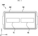
FIG. 3 is a top view illustrating the optical interference blocking structure according to the present invention. -
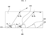
FIGS. 4 and5 are schematic diagrams illustrating a coupling relationship between a cover portion and a total reflection prevention portion according to the present invention. -
FIG. 6 is a partial perspective view illustrating an example of the total reflection prevention portion according to the present invention. -
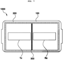
FIG. 7 is a top view illustrating a shielding wall of the optical interference blocking structure according to the present invention. -
FIG. 8 is a cross-sectional view illustrating the shielding wall of the optical interference blocking structure according to the present invention. -
FIG. 9 is a top view illustrating a first example of the optical interference blocking structure according to the present invention. -
FIG. 10 is a cross-sectional view illustrating the first example of the optical interference blocking structure according to the present invention. -
FIG. 11 is a top view illustrating a second example of the optical interference blocking structure according to the present invention. -
- 1000: Optical interference blocking structure
- 100: Cover portion
- 200: Total reflection prevention portion
- 210: First inclined surface
- 220: Second inclined surface
- 230: Third inclined surface
- 231: Concave inclined surface
- 232: Convex inclined surface
- 300: Shielding wall
- Tx: Transmitter
- Rx: Receiver
- Hereinafter, the technical spirit of the present invention will be described in more detail with reference to the accompanying drawings. Terms and words used in the present specification and claims are not to be construed as general or dictionary meanings, but are to be construed as meanings and concepts meeting the technical ideas of the present invention based on a principle that the present inventors may appropriately define the concepts of terms in order to describe their inventions in the best mode.
- Hereinafter, a basic configuration of an optical
interference blocking structure 1000 according to the present invention will be described in more detail with reference toFIGS. 2 and3 . - As illustrated in
FIG. 2 , the opticalinterference blocking structure 1000 according to the present invention is applied to a light detection and ranging (LiDAR) system including a transmitter Tx that transmits light in one direction and a receiver Rx that receives light in one direction, and the opticalinterference blocking structure 1000 according to the present invention may include acover portion 100 which is a window provided in one direction of the LiDAR system. That is, thecover portion 100 may cover both a side where the transmitter Tx generates light and a side where the receiver Rx receives light. At this time, thecover portion 100 may be formed of a material that may transmit light, such as glass or silicon. Thecover portion 100 may protect the transmitter Tx and the receiver Rx of the LiDAR system from an external force. - At this time, the optical
interference blocking structure 1000 according to the present invention may further include a totalreflection prevention portion 200 that protrudes from thecover portion 100 toward the LiDAR system. The totalreflection prevention portion 200 may be formed integrally with thecover portion 100, may protrude from thecover portion 100 toward the LiDAR system, and may have a specific shape with predetermined protrusions and grooves formed at a protruding end portion. At this time, light generated from the transmitter Tx and incident on thecover portion 100 may not be totally reflected within thecover portion 100 but be refracted and move to the outside of thecover portion 100 due to the shape of the totalreflection prevention portion 200. Accordingly, light transmitted from the transmitter Tx may not be directly transmitted to the receiver Rx, but may be transmitted to the receiver Rx after being reflected by a target. The opticalinterference blocking structure 1000 according to the present invention may include the totalreflection prevention portion 200 to reduce noise that may degrade performance of the LiDAR system and enhance accuracy and precision of a sensor signal. - In addition, as illustrated in
FIG. 3 , the totalreflection prevention portion 200 may be formed along an edge of thecover portion 100. The transmitter Tx and the receiver Rx may generate and receive light in a Z-axis direction inFIG. 3 , and the light generated by the transmitter Tx may radially move based on a light generation point inside the transmitter Tx. The light moving radially may be reflected by a housing of the LiDAR system or the like and incident on thecover portion 100, and the light incident on thecover portion 100 may be totally reflected and move inside thecover portion 100 according to an incident angle of the light and be directly incident on the receiver Rx. In this regard, the totalreflection prevention portion 200 may be formed at the edge of thecover portion 100, so that light incident on thecover portion 100 may be refracted by the totalreflection prevention portion 200 positioned at the edge without being totally reflected and move to the outside of thecover portion 100 when being directed toward the receiver Rx even though the light incident on thecover portion 100 is totally reflected by a portion where the totalreflection prevention portion 200 is not formed. - Hereinafter, a shape limitation of the total
reflection prevention portion 200 according to the present invention will be described in more detail with reference toFIGS. 4 and5 . - As illustrated in
FIG. 4 , thecover portion 100 may have a flat surface, and the totalreflection prevention portion 200 may have at least one firstinclined surface 210 forming a predetermined inclination angle with one surface of thecover portion 100. That is, the totalreflection prevention portion 200 may have a saw-toothed shape with triangular prism-shaped grooves or protrusions, and a surface of the totalreflection prevention portion 200 that corresponds to the firstinclined surface 210 may have the largest area. More specifically, the inclination angle of the firstinclined surface 210 of the totalreflection prevention portion 200 may satisfy the followingExpression 1.
inclined surface 210 and one surface of thecover portion 100, θi: the incident angle of the light, and θc : a critical angle of the material of the cover portion 100) - Here, θc may be a constant value determined by the material of the
cover portion 100. For example, in a case where thecover portion 100 is formed of polycarbonate, θc may be 39.68 degrees (≈ 40 degrees). In addition, a range of θi may be predetermined depending on specifications and structures of thecover portion 100 and the LiDAR system. For example, assuming that the inclination angle
inclined surface 210 is determined to be 20 degrees and η " c is 40 degrees, when the value of the incident angle θil is 50 degrees, the right side of the expression is 10 degrees, which satisfiesExpression 1 above, and thus, the light may be refracted without total reflection and move to the outside of thecover portion 100. On the other hand, when the value of the incident angle
Expression 1 above, and thus, the light may be totally reflected and act as noise. In other words,
cover portion 100 when operating the LiDAR system. - As illustrated in
FIG. 5 , thecover portion 100 may have a curved surface, and the totalreflection prevention portion 200 may have at least one secondinclined surface 220 forming a predetermined inclination angle with one surface of thecover portion 100. That is, the totalreflection prevention portion 200 may have a saw-toothed shape with triangular prism-shaped grooves or protrusions, and a surface of the totalreflection prevention portion 200 that corresponds to the secondinclined surface 220 may have the largest area. More specifically, the inclination angle of the secondinclined surface 220 of the totalreflection prevention portion 200 may satisfy the following Expression 2.
inclined surface 220 and one surface of thecover portion 100, θi: the incident angle of the light, θc: the critical angle of the material of thecover portion 100, θ r1: a tangential angle at a light incident point on an inner curved surface of thecover portion 100, and θ r2: a tangential angle at a light emission point on an outer curved surface of the cover portion 100) - Here, θc may be a constant value determined by the material of the
cover portion 100. For example, in a case where thecover portion 100 is formed of polycarbonate, θc may be 39.68 degrees (≈ 40 degrees). In addition, a correlation between θi, θ r1, and θ r2 and ranges of θi, θ r1, and θ r2 may be predetermined depending on the specifications and structures of thecover portion 100 and the LiDAR system. For example, assuming that the inclination angle θ d2 of the secondinclined surface 220 is determined to be 20 degrees and θc is 40 degrees, when the tangential angle θ r11 at the light incident point is 20 degrees, and the value of the incident angle θ i3 is 60 degrees, the tangential angle θ r21 at the light emission point is determined to be 7 degrees, and the right side of the expression is 27 degrees, which satisfies Expression 2 above, and thus, the light may be refracted without total reflection and move to the outside of thecover portion 100. In addition, when the tangential angle θ r12 at the light incident point is 30 degrees, and the value of the incident angle θ i4 is 70 degrees, θ r22 is determined to be 45 degrees and the right side of the expression is 35 degrees, which also satisfies Expression 2 above, and thus, the light may be refracted without total reflection and move to the outside of thecover portion 100. In other words,
cover portion 100 and the shape of the curved surface of thecover portion 100 when operating the LiDAR system. - Hereinafter, an example of the shape of the total
reflection prevention portion 200 according to the present invention will be described in more detail with reference toFIG. 6 . - In an example, the total
reflection prevention portion 200 may have at least one thirdinclined surface 230 whose slope connecting both ends forms a predetermined inclination angle with one surface of thecover portion 100 as illustrated inFIG. 6 . At this time, the totalreflection prevention portion 200 may be formed in a saw-toothed shape, and the thirdinclined surface 230 may be an inclined surface having the largest area. At this time, the inclination angle of the thirdinclined surface 230 may follow the inclination angle θ d1 of the firstinclined surface 210 or the inclination angle θ d2 of the secondinclined surface 220 depending on the shape of thecover portion 100. - In addition, the third
inclined surface 230 may be formed as a curved surface having a predetermined curvature. More specifically, the thirdinclined surface 230 may include a convexinclined surface 232 that is convex with respect to thecover portion 100, and a concaveinclined surface 231 connecting the convexinclined surfaces 232 and having a smaller area than the convexinclined surface 232. - Hereinafter, a shielding
wall 300 of the opticalinterference blocking structure 1000 according to the present invention will be described in more detail with reference toFIGS. 7 and8 . - As illustrated in
FIG. 7 , the opticalinterference blocking structure 1000 according to the present invention may further include the shieldingwall 300 which is a wall installed between the transmitter Tx and the receiver Rx. Here, the shieldingwall 300 may contain a material that does not transmit light and may be formed of a metal material. The opticalinterference blocking structure 1000 according to the present invention may include the shieldingwall 300 to block transmission of light, thereby preventing light transmitted from the transmitter Tx from being transmitted to the receiver Rx. Accordingly, as illustrated inFIG. 8 , proximity noise detected when a laser pulse emitted from the transmitter Tx is reflected from lens surfaces of the transmitter Tx and the receiver Rx, or internal scattering in the housing or the like included in the LiDAR system may be removed. - Hereinafter, a first example of the optical
interference blocking structure 1000 according to the present invention will be described in more detail with reference toFIGS. 9 and10 . - As illustrated in
FIG. 9 , in the first example of the opticalinterference blocking structure 1000 according to the present invention, the opticalinterference blocking structure 1000 according to the present invention may include the shieldingwall 300 installed between the transmitter Tx and the receiver Rx, the shieldingwall 300 and thecover portion 100 may be disposed while being spaced apart from each other at a predetermined interval, and the totalreflection prevention portion 200 may also be formed in a region of thecover portion 100 that faces the shieldingwall 300 in addition to an edge region of thecover portion 100. Accordingly, even when noise is totally reflected along a surface of thecover portion 100 on which the total reflection prevention portion is not formed and reaches the vicinity of the shieldingwall 300, total reflection of the noise may be secondarily prevented by the totalreflection prevention portion 200 formed in the region corresponding to the shieldingwall 300, and ultimately, light that may generate noise may be directed toward the outside of thecover portion 100, that is, toward the target as illustrated inFIG. 10 . - Hereinafter, a second example of the optical
interference blocking structure 1000 according to the present invention will be described in more detail with reference toFIG. 11 . - As illustrated in
FIG. 11 , the totalreflection prevention portion 200 may be formed along the edge of thecover portion 100 and may be formed only at an edge of a region where the transmitter Tx is positioned among regions divided by the shieldingwall 300. In fact, the totalreflection prevention portion 200 according to the present invention aims to prevent light generated from the transmitter Tx from reaching the receiver Rx. Therefore, high noise removal performance may be expected only by blocking noise occurring near the transmitter Tx. That is, an effect of maintaining the noise removal performance and increasing manufacturing efficiency may be expected by applying the second example of the opticalinterference blocking structure 1000 according to the present invention. - The optical interference blocking structure according to the present invention with the configuration as described above may more effectively achieve development of a LiDAR sensor by applying a design to prevent total reflection to a cover of the LiDAR sensor, thereby reducing noise that may degrade sensor performance, enhancing accuracy and precision of a sensor signal, and ultimately increasing a signal-to-noise ratio (SNR).
- Therefore, the spirit of the present invention should not be limited to the described embodiments, but the claims and all of modifications equal or equivalent to the claims are intended to fall within the scope and spirit of the present invention.
Claims (16)
- An optical interference blocking structure for a light detection and ranging (LiDAR) system including a transmitter that transmits light in one direction and a receiver that receives light in the one direction, the optical interference blocking structure comprising: aa cover portion which is a window provided in the one direction of the LiDAR system; anda total reflection prevention portion protruding from the cover portion toward the LiDAR system,wherein the total reflection prevention portion includes a protrusion and a groove having a uniform shape and formed to prevent internal total reflection of incident light.
- The optical interference blocking structure of claim 1,wherein the cover portion has a flat surface, andwherein the total reflection prevention portion is formed along an edge of the cover portion and include at least one first inclined surface forming a predetermined inclination angle with one surface of the cover portion.
- The optical interference blocking structure of claim 2,
wherein the at least one first inclined surface of the cover portion and the flat surface of the cover portion form a shape of triangular prism. - The optical interference blocking structure of claim 2, wherein the first inclined surface of the total reflection prevention portion satisfies the following expression:

where θ d1 is the inclination angle formed by the first inclined surface and the one surface of the cover portion, θi is an incident angle of the light, and θc is a critical angle of a material of the cover portion. - The optical interference blocking structure of claim 1,wherein the cover portion has a curved surface, andwherein the total reflection prevention portion is formed along an edge of the cover portion and includes at least one second inclined surface forming a predetermined inclination angle with the one surface of the cover portion.
- The optical interference blocking structure of claim 5,
wherein the at least one second inclined surface of the cover portion and the one surface of the cover portion form a shape of triangular prism. - The optical interference blocking structure of claim 5, wherein the second inclined surface of the total reflection prevention portion satisfies the following expression:

- The optical interference blocking structure of claim 1,wherein the total reflection prevention portion includes at least one third inclined surface whose slope connecting first and second ends forms a predetermined inclination angle with the one surface of the cover portion, andwherein the third inclined surface is formed as a curved surface having a predetermined curvature.
- The optical interference blocking structure of claim 8,
wherein the at least one third inclined surface of the cover portion and the one surface of the cover portion form a shape of triangular prism. - The optical interference blocking structure of claim 8, wherein the third inclined surface includes:a convex inclined surface that is convex with respect to the cover portion; anda concave inclined surface that connects the convex inclined surfaces and is concave with respect to the cover portion.
- The optical interference blocking structure of claim 1, further comprising:a shielding wall installed between the transmitter and the receiver,wherein the shielding wall contains a material that does not transmit the light.
- The optical interference blocking structure of claim 11, wherein the total reflection prevention portion is formed in a region of the cover portion facing the shielding wall.
- The optical interference blocking structure of claim 11, wherein the total reflection prevention portion is formed along an edge of the cover portion
- The optical interference blocking structure of claim 13, wherein the total reflection prevention portion is formed in a region of the cover portion facing the shielding wall.
- The optical interference blocking structure of claim 13, wherein the cover portion cover a side of the optical interference blocking structure where the transmitter Tx generates the light and a side of the optical interference blocking structure where the receiver Rx receives light.
- The optical interference blocking structure of claim 13, wherein the total reflection prevention portion is formed only at an edge of a region of the cover portion where the transmitter is positioned among regions of the cover portion divided by the shielding wall.
Applications Claiming Priority (1)
| Application Number | Priority Date | Filing Date | Title |
|---|---|---|---|
| KR1020230138142A KR20250054937A (en) | 2023-10-17 | 2023-10-17 | Optical interference blocking structure |
Publications (1)
| Publication Number | Publication Date |
|---|---|
| EP4542185A1 true EP4542185A1 (en) | 2025-04-23 |
Family
ID=92843201
Family Applications (1)
| Application Number | Title | Priority Date | Filing Date |
|---|---|---|---|
| EP24200992.6A Pending EP4542185A1 (en) | 2023-10-17 | 2024-09-18 | Optical interference blocking structure |
Country Status (4)
| Country | Link |
|---|---|
| US (1) | US20250123433A1 (en) |
| EP (1) | EP4542185A1 (en) |
| KR (1) | KR20250054937A (en) |
| CN (1) | CN119846597A (en) |
Citations (5)
| Publication number | Priority date | Publication date | Assignee | Title |
|---|---|---|---|---|
| WO2021026809A1 (en) * | 2019-08-14 | 2021-02-18 | 深圳市速腾聚创科技有限公司 | Flash lidar |
| US20210148761A1 (en) * | 2019-11-18 | 2021-05-20 | Toyoda Gosei Co., Ltd. | Near-infrared sensor cover |
| KR20220004456A (en) | 2020-07-03 | 2022-01-11 | 주식회사 만도모빌리티솔루션즈 | Lidar apparatus |
| US20230079384A1 (en) * | 2021-09-13 | 2023-03-16 | Shunsin Technology (Zhong Shan) Limited | Optical sensor and method for manufacturing optical sensor |
| KR20230138142A (en) | 2022-03-23 | 2023-10-05 | 에스케이하이닉스 주식회사 | Memory system and operating method thereof |
-
2023
- 2023-10-17 KR KR1020230138142A patent/KR20250054937A/en active Pending
-
2024
- 2024-07-02 US US18/761,461 patent/US20250123433A1/en active Pending
- 2024-09-18 EP EP24200992.6A patent/EP4542185A1/en active Pending
- 2024-10-15 CN CN202411436800.8A patent/CN119846597A/en active Pending
Patent Citations (5)
| Publication number | Priority date | Publication date | Assignee | Title |
|---|---|---|---|---|
| WO2021026809A1 (en) * | 2019-08-14 | 2021-02-18 | 深圳市速腾聚创科技有限公司 | Flash lidar |
| US20210148761A1 (en) * | 2019-11-18 | 2021-05-20 | Toyoda Gosei Co., Ltd. | Near-infrared sensor cover |
| KR20220004456A (en) | 2020-07-03 | 2022-01-11 | 주식회사 만도모빌리티솔루션즈 | Lidar apparatus |
| US20230079384A1 (en) * | 2021-09-13 | 2023-03-16 | Shunsin Technology (Zhong Shan) Limited | Optical sensor and method for manufacturing optical sensor |
| KR20230138142A (en) | 2022-03-23 | 2023-10-05 | 에스케이하이닉스 주식회사 | Memory system and operating method thereof |
Also Published As
| Publication number | Publication date |
|---|---|
| CN119846597A (en) | 2025-04-18 |
| US20250123433A1 (en) | 2025-04-17 |
| KR20250054937A (en) | 2025-04-24 |
Similar Documents
| Publication | Publication Date | Title |
|---|---|---|
| EP2975447B1 (en) | Laser scanner | |
| US8068215B2 (en) | Laser distance meter | |
| KR20200102900A (en) | Lidar device | |
| CN216083083U (en) | Coaxial optical system for laser ranging | |
| US7463339B2 (en) | Device for measuring the distance to far-off objects and close objects | |
| US20250123433A1 (en) | Optical interference blocking structure | |
| US11513192B2 (en) | Lidar signal processing apparatus and method | |
| US5838454A (en) | Sensor arrangement for detecting the degree of wetting of a windshield | |
| US20070035954A1 (en) | Device for detecting the dirt accumulation on a transparent covering pane in front of a optical unit | |
| US6737665B1 (en) | Edge detector | |
| KR102178376B1 (en) | Omnidirectional rotationless scanning lidar system | |
| US10725154B2 (en) | Optical detection of an object in a turbid medium using an optical vortex | |
| CN115825929B (en) | Laser receiving device and laser radar | |
| US12517230B2 (en) | Photosensor having range parallax compensation | |
| GB2366107A (en) | Technique for increasing the optical signal/noise ratio of a laser range finder | |
| EP0913716A2 (en) | Reflector type prism and reflector type prism forming die | |
| KR20250071474A (en) | Optical interference blocking structure and its design method | |
| JPH10132559A (en) | Distance sensor | |
| JP2000258540A (en) | Radiation detector | |
| KR20050077455A (en) | Optical antenna and wireless optical system using the same | |
| EP0498429A1 (en) | Improved target detector eliminating in-range sensitivity | |
| US20250314747A1 (en) | Lidar and movable device | |
| EP4056965A1 (en) | Optical sensing system | |
| CN220064367U (en) | Laser radar | |
| US6100983A (en) | Object sensing apparatus having filter member |
Legal Events
| Date | Code | Title | Description |
|---|---|---|---|
| PUAI | Public reference made under article 153(3) epc to a published international application that has entered the european phase |
Free format text: ORIGINAL CODE: 0009012 |
|
| STAA | Information on the status of an ep patent application or granted ep patent |
Free format text: STATUS: REQUEST FOR EXAMINATION WAS MADE |
|
| 17P | Request for examination filed |
Effective date: 20241017 |
|
| AK | Designated contracting states |
Kind code of ref document: A1 Designated state(s): AL AT BE BG CH CY CZ DE DK EE ES FI FR GB GR HR HU IE IS IT LI LT LU LV MC ME MK MT NL NO PL PT RO RS SE SI SK SM TR |
|
| STAA | Information on the status of an ep patent application or granted ep patent |
Free format text: STATUS: EXAMINATION IS IN PROGRESS |
|
| 17Q | First examination report despatched |
Effective date: 20251023 |