EP4542175A1 - Sensor device - Google Patents
Sensor device Download PDFInfo
- Publication number
- EP4542175A1 EP4542175A1 EP23824223.4A EP23824223A EP4542175A1 EP 4542175 A1 EP4542175 A1 EP 4542175A1 EP 23824223 A EP23824223 A EP 23824223A EP 4542175 A1 EP4542175 A1 EP 4542175A1
- Authority
- EP
- European Patent Office
- Prior art keywords
- region
- collector
- disposed
- axial direction
- stator
- Prior art date
- Legal status (The legal status is an assumption and is not a legal conclusion. Google has not performed a legal analysis and makes no representation as to the accuracy of the status listed.)
- Pending
Links
Images






Classifications
-
- G—PHYSICS
- G01—MEASURING; TESTING
- G01D—MEASURING NOT SPECIALLY ADAPTED FOR A SPECIFIC VARIABLE; ARRANGEMENTS FOR MEASURING TWO OR MORE VARIABLES NOT COVERED IN A SINGLE OTHER SUBCLASS; TARIFF METERING APPARATUS; MEASURING OR TESTING NOT OTHERWISE PROVIDED FOR
- G01D5/00—Mechanical means for transferring the output of a sensing member; Means for converting the output of a sensing member to another variable where the form or nature of the sensing member does not constrain the means for converting; Transducers not specially adapted for a specific variable
- G01D5/12—Mechanical means for transferring the output of a sensing member; Means for converting the output of a sensing member to another variable where the form or nature of the sensing member does not constrain the means for converting; Transducers not specially adapted for a specific variable using electric or magnetic means
- G01D5/14—Mechanical means for transferring the output of a sensing member; Means for converting the output of a sensing member to another variable where the form or nature of the sensing member does not constrain the means for converting; Transducers not specially adapted for a specific variable using electric or magnetic means influencing the magnitude of a current or voltage
- G01D5/142—Mechanical means for transferring the output of a sensing member; Means for converting the output of a sensing member to another variable where the form or nature of the sensing member does not constrain the means for converting; Transducers not specially adapted for a specific variable using electric or magnetic means influencing the magnitude of a current or voltage using Hall-effect devices
- G01D5/145—Mechanical means for transferring the output of a sensing member; Means for converting the output of a sensing member to another variable where the form or nature of the sensing member does not constrain the means for converting; Transducers not specially adapted for a specific variable using electric or magnetic means influencing the magnitude of a current or voltage using Hall-effect devices influenced by the relative movement between the Hall device and magnetic fields
-
- B—PERFORMING OPERATIONS; TRANSPORTING
- B62—LAND VEHICLES FOR TRAVELLING OTHERWISE THAN ON RAILS
- B62D—MOTOR VEHICLES; TRAILERS
- B62D15/00—Steering not otherwise provided for
- B62D15/02—Steering position indicators ; Steering position determination; Steering aids
- B62D15/021—Determination of steering angle
-
- B—PERFORMING OPERATIONS; TRANSPORTING
- B62—LAND VEHICLES FOR TRAVELLING OTHERWISE THAN ON RAILS
- B62D—MOTOR VEHICLES; TRAILERS
- B62D6/00—Arrangements for automatically controlling steering depending on driving conditions sensed and responded to, e.g. control circuits
- B62D6/08—Arrangements for automatically controlling steering depending on driving conditions sensed and responded to, e.g. control circuits responsive only to driver input torque
- B62D6/10—Arrangements for automatically controlling steering depending on driving conditions sensed and responded to, e.g. control circuits responsive only to driver input torque characterised by means for sensing or determining torque
-
- G—PHYSICS
- G01—MEASURING; TESTING
- G01B—MEASURING LENGTH, THICKNESS OR SIMILAR LINEAR DIMENSIONS; MEASURING ANGLES; MEASURING AREAS; MEASURING IRREGULARITIES OF SURFACES OR CONTOURS
- G01B7/00—Measuring arrangements characterised by the use of electric or magnetic techniques
- G01B7/30—Measuring arrangements characterised by the use of electric or magnetic techniques for measuring angles or tapers; for testing the alignment of axes
-
- G—PHYSICS
- G01—MEASURING; TESTING
- G01D—MEASURING NOT SPECIALLY ADAPTED FOR A SPECIFIC VARIABLE; ARRANGEMENTS FOR MEASURING TWO OR MORE VARIABLES NOT COVERED IN A SINGLE OTHER SUBCLASS; TARIFF METERING APPARATUS; MEASURING OR TESTING NOT OTHERWISE PROVIDED FOR
- G01D5/00—Mechanical means for transferring the output of a sensing member; Means for converting the output of a sensing member to another variable where the form or nature of the sensing member does not constrain the means for converting; Transducers not specially adapted for a specific variable
- G01D5/12—Mechanical means for transferring the output of a sensing member; Means for converting the output of a sensing member to another variable where the form or nature of the sensing member does not constrain the means for converting; Transducers not specially adapted for a specific variable using electric or magnetic means
- G01D5/14—Mechanical means for transferring the output of a sensing member; Means for converting the output of a sensing member to another variable where the form or nature of the sensing member does not constrain the means for converting; Transducers not specially adapted for a specific variable using electric or magnetic means influencing the magnitude of a current or voltage
-
- G—PHYSICS
- G01—MEASURING; TESTING
- G01L—MEASURING FORCE, STRESS, TORQUE, WORK, MECHANICAL POWER, MECHANICAL EFFICIENCY, OR FLUID PRESSURE
- G01L3/00—Measuring torque, work, mechanical power, or mechanical efficiency, in general
- G01L3/02—Rotary-transmission dynamometers
- G01L3/04—Rotary-transmission dynamometers wherein the torque-transmitting element comprises a torsionally-flexible shaft
- G01L3/10—Rotary-transmission dynamometers wherein the torque-transmitting element comprises a torsionally-flexible shaft involving electric or magnetic means for indicating
-
- G—PHYSICS
- G01—MEASURING; TESTING
- G01L—MEASURING FORCE, STRESS, TORQUE, WORK, MECHANICAL POWER, MECHANICAL EFFICIENCY, OR FLUID PRESSURE
- G01L3/00—Measuring torque, work, mechanical power, or mechanical efficiency, in general
- G01L3/02—Rotary-transmission dynamometers
- G01L3/04—Rotary-transmission dynamometers wherein the torque-transmitting element comprises a torsionally-flexible shaft
- G01L3/10—Rotary-transmission dynamometers wherein the torque-transmitting element comprises a torsionally-flexible shaft involving electric or magnetic means for indicating
- G01L3/101—Rotary-transmission dynamometers wherein the torque-transmitting element comprises a torsionally-flexible shaft involving electric or magnetic means for indicating involving magnetic or electromagnetic means
- G01L3/104—Rotary-transmission dynamometers wherein the torque-transmitting element comprises a torsionally-flexible shaft involving electric or magnetic means for indicating involving magnetic or electromagnetic means involving permanent magnets
-
- G—PHYSICS
- G01—MEASURING; TESTING
- G01L—MEASURING FORCE, STRESS, TORQUE, WORK, MECHANICAL POWER, MECHANICAL EFFICIENCY, OR FLUID PRESSURE
- G01L5/00—Apparatus for, or methods of, measuring force, work, mechanical power, or torque, specially adapted for specific purposes
- G01L5/22—Apparatus for, or methods of, measuring force, work, mechanical power, or torque, specially adapted for specific purposes for measuring the force applied to control members, e.g. control members of vehicles, triggers
- G01L5/221—Apparatus for, or methods of, measuring force, work, mechanical power, or torque, specially adapted for specific purposes for measuring the force applied to control members, e.g. control members of vehicles, triggers to steering wheels, e.g. for power assisted steering
-
- B—PERFORMING OPERATIONS; TRANSPORTING
- B60—VEHICLES IN GENERAL
- B60G—VEHICLE SUSPENSION ARRANGEMENTS
- B60G2400/00—Indexing codes relating to detected, measured or calculated conditions or factors
- B60G2400/05—Attitude
- B60G2400/051—Angle
- B60G2400/0516—Angular position of a suspension element
-
- B—PERFORMING OPERATIONS; TRANSPORTING
- B60—VEHICLES IN GENERAL
- B60Y—INDEXING SCHEME RELATING TO ASPECTS CROSS-CUTTING VEHICLE TECHNOLOGY
- B60Y2400/00—Special features of vehicle units
- B60Y2400/30—Sensors
- B60Y2400/301—Sensors for position or displacement
- B60Y2400/3012—Sensors for position or displacement using Hall effect
-
- B—PERFORMING OPERATIONS; TRANSPORTING
- B62—LAND VEHICLES FOR TRAVELLING OTHERWISE THAN ON RAILS
- B62D—MOTOR VEHICLES; TRAILERS
- B62D15/00—Steering not otherwise provided for
- B62D15/02—Steering position indicators ; Steering position determination; Steering aids
- B62D15/021—Determination of steering angle
- B62D15/0215—Determination of steering angle by measuring on the steering column
Definitions
- Embodiments relate to a sensor device.
- a power steering system (electronic power system (hereinafter, referred to as an 'EPS')) ensures turning stability and provides a quick restoring force by allowing an electronic control unit to operate a motor in accordance with a driving condition, thereby allowing a driver to perform safe driving.
- the EPS includes a sensor device configured to measure torque, a steering angle, and the like of a steering shaft in order to provide appropriate torque.
- the sensor device is a device that measures a degree of torsion of a torsion bar.
- the steering shaft includes an input shaft connected to a steering wheel, and an output shaft connected to a wheel side power transmission configuration, and the torsion bar is a member configured to connect the and input shaft and the output shaft.
- the sensor device includes a housing, a rotor, a stator including stator teeth, and a collector.
- the collector is disposed outside the stator teeth.
- the collector serves as a passageway for an external magnetic field when the external magnetic field is formed, which causes a problem in that the collector affects a magnetic flux value of a sensor.
- an output value of the sensor device changes, which causes a problem in that a degree of torsion of the torsion bar cannot be accurately measured.
- An object of an embodiment is to provide a sensor device capable of compensating for the amount of change in output value of a sensor caused by external magnetism.
- An embodiment may provide a sensor device including a rotor, a stator disposed to correspond to the rotor, first and second outer collectors disposed at one side of the stator, first and second inner collectors disposed between the first and second outer collectors, and a Hall sensor disposed between the first inner collector and the second inner collector.
- the first outer collector may include: a first region positioned at a first side of the stator in an axial direction; a second region positioned at a second side of the stator; and a third region configured to connect the first region and the second region
- the second outer collector may include: a fourth region positioned at the second side of the stator in the axial direction; a fifth region positioned at the first side of the stator; and a sixth region configured to connect the fourth region and the fifth region.
- the first inner collector and the second inner collector may be disposed between the second region and the fifth region.
- the first outer collector and the first inner collector may be disposed to be spaced apart from each other, and the second outer collector and the second inner collector may be disposed to be spaced apart from each other.
- the second region, the fifth region, the first inner collector, and the second inner collector may overlap one another in the axial direction.
- the second region may include a first bent portion bent toward the first side, and the first bent portion may be disposed to overlap the first inner collector in the direction perpendicular to the axial direction.
- the first bent portion may be disposed to overlap the Hall sensor in the direction perpendicular to the axial direction.
- the first region and the second region may be disposed on planes perpendicular to the axial direction, and the third region may be disposed perpendicularly to the first region and the second region.
- the fourth region and the fifth region may be disposed on planes perpendicular to the axial direction, and the sixth region may be disposed perpendicularly to the fourth region and the fifth region.
- the second region may include an inner surface and an outer surface, the inner surface may include a curved surface, and the outer surface may include a protruding portion protruding outward in the direction perpendicular to the axial direction.
- the fourth region may include an inner surface and an outer surface, the inner surface may include a curved surface, and the outer surface may include a second protruding portion protruding outward in a direction perpendicular to an axial center.
- the first inner collector may include a seventh region disposed to correspond to the second region, an eighth region bent from the seventh region toward the first side, and a ninth region bent from the eighth region in the direction perpendicular to the axial direction.
- the second inner collector may include a tenth region disposed to correspond to the fifth region, an eleventh region bent from the fifth region toward the second side, and a twelfth region bent from the eleventh region in the direction perpendicular to the axial direction.
- An embodiment may provide a sensor device including: a rotor; a stator disposed to correspond to the rotor; a first outer collector disposed at one side of the stator and configured to acquire a magnetic field from the stator; a first inner collector disposed to be spaced apart from the first outer collector and configured to acquire a magnetic field from the first outer collector; and a first Hall sensor unit disposed to acquire a magnetic field from the first inner collector.
- the first outer collector may be disposed to be spaced apart from the stator, and the first inner collector may be disposed to be spaced apart from the first outer collector.
- the magnetic field acquired from the stator may be transmitted to the first Hall sensor unit through the first outer collector and the first inner collector, and an external magnetic field in an axial direction may be collected at one side of the first outer collector based on the axial direction and discharged to the other side of the first outer collector.
- the first outer collector may include: a first region positioned at a first side of the stator in the axial direction; a second region positioned at a second side of the stator; and a third region configured to connect the first region and the second region, and the external magnetic field in the axial direction may be collected in the first region and discharged to the outside of the third region through the second region.
- An external magnetic field in a direction perpendicular to an axial direction may be collected at one side of the first outer collector based on the direction perpendicular to the axial direction and discharged to the other side of the first outer collector.
- the first outer collector may include a first region positioned at a first side of the stator in the axial direction, a second region positioned at a second side of the stator, and a third region configured to connect the first region and the second region, the second region may include a first bent portion bent toward the second side, and an external magnetic field in a direction perpendicular to the axial direction may be collected in the first bent portion.
- the sensor device may further include a second outer collector disposed at the other side of the stator and configured to acquire a magnetic field from the stator, a second inner collector disposed to be spaced apart from the second outer collector and configured to acquire a magnetic field from the second outer collector, and a second Hall sensor unit disposed to acquire a magnetic field from the first inner collector and the second inner collector.
- the second outer collector may be disposed to be spaced apart from the stator, and the second inner collector may be disposed to be spaced apart from the second outer collector.
- the magnetic field acquired from the stator may be transmitted to the first Hall sensor unit and the second Hall sensor unit through the second outer collector and the second inner collector, and an external magnetic field in an axial direction may be collected at one side of the second outer collector and discharged to the other side of the second outer collector.
- the second outer collector may include a fourth region positioned at the second side of the stator in the axial direction, a fifth region positioned at the first side of the stator, and a sixth region configured to connect the fourth region and the fifth region, and the external magnetic field in the axial direction may be collected in the sixth region and discharged to the outside of the fourth region through the fifth region.
- the external magnetic field in the direction perpendicular to the axial direction may be collected at one side of the second outer collector in the direction perpendicular to the axial direction and discharged to the other side of the second outer collector.
- the second outer collector may include a fourth region positioned at the second side of the stator in the axial direction, a fifth region positioned at the second side of the stator, and a sixth region configured to connect the fourth region and the fifth region, the fifth region may include a second bent portion bent toward the second side, and the external magnetic field in the direction perpendicular to the axial direction may be collected in the second bent portion.
- the outer collector serves as a shield against an external magnetic field, thereby reducing an influence of the external magnetic field on the Hall sensor.
- the outer collector and the inner collector are separated, such that an external magnetic field may flow more effectively.
- the outer collector and the inner collector are separated, such that the outer collector and the inner collector are easily assembled.
- a direction perpendicular to an axial direction of a sensor device is referred to as a radial direction
- a direction in which a circle having a radius in the radial direction is defined about an axial center is referred to as a circumferential direction.
- FIG. 1 is a perspective view illustrating a sensor device according to an embodiment
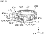
- FIG. 2 is a view illustrating a rotor 100, a stator 200, and collectors of the sensor device illustrated in FIG. 1 .
- the sensor device may include the rotor 100, the stator 200, a first outer collector 300, a second outer collector 400, a first inner collector 500, a second inner collector 600, and a Hall sensor 700.
- an x-axis indicates a direction perpendicular to the axial direction
- a y-axis indicates a direction perpendicular to the direction indicated by the x-axis and perpendicular to the axial direction
- a z-axis is the axial direction.
- the stator 200 may be connected to an output shaft (not illustrated), and the rotor 100, which has at least a part rotatably disposed on the stator 200, may be connected to an input shaft (not illustrated).
- the present disclosure is not necessarily limited thereto.
- the rotor 100 may be disposed to be rotatable relative to the stator 200.
- the term 'inside' may mean a direction disposed toward the center based on the radial direction
- the term 'outside' may mean a direction opposite to the inside.
- the rotor 100 may include magnets.
- the magnet may be disposed inside the stator 200.
- the magnet may be connected to the input shaft through a separate holder.
- a housing 10 is disposed outside the stator 200.
- the housing 10 may include an upper housing 11 and a lower housing 12.
- the stator 200, the first outer collector 300, the second outer collector 400, the first inner collector 500, and the second inner collector 600 may be fixed to the housing 10.
- the first outer collector 300 may be disposed in the axial direction from a first side toward a second side of the stator 200.
- the second outer collector 400 may be disposed in the axial direction from the second side toward the first side of the stator 200.
- the first side refers to one side of the stator 200 based on the axial direction
- the second side refers to the other side of the stator 200 based on the axial direction.
- the first inner collector 500 and the second inner collector 600 are disposed to correspond to the Hall sensor 700.
- the Hall sensor 700 may include a first Hall sensor unit 710 and a second Hall sensor unit 720.
- the first Hall sensor unit 710 and the second Hall sensor unit 720 are disposed between the first inner collector 500 and the second inner collector 600 and detect a change in magnetic field generated between the stator 200 and the rotor 100.
- the first Hall sensor unit 710 and the second Hall sensor unit 720 may each be a Hall IC.
- the sensor device measures torque on the basis of the detected change in the magnetic field.
- the first outer collector 300 and the second outer collector 400 may be identical in shape and size and different in positions.
- the first inner collector 500 and the second inner collector 600 may also be identical in shape and size and different in positions.
- the first inner collector 500 and the second inner collector 600 are positioned between the first outer collector 300 and the second outer collector 400 in the axial direction. Therefore, the first inner collector 500 and the second inner collector 600 are relatively less affected by the external magnetic field, which is applied in the axial direction, than the first outer collector 300 and the second outer collector 400.
- the first inner collector 500 may be disposed to be spaced apart from the first outer collector in the axial direction. Further, the second inner collector 600 may be disposed to be spaced apart from the second outer collector in the axial direction.
- the first outer collector 300 or the second outer collector 400 guides a flow of the magnetic field, which is generated between the rotor 100 and the stator 200, to the first inner collector 500 or the second inner collector 600.
- the first outer collector 300 or the second outer collector 400 serves to guide the flow of the external magnetic field so that the external magnetic field is discharged to the outside without flowing to the Hall sensor 700.
- the first inner collector 500 and the second inner collector 600 serve to transmit the magnetic flow, which is generated between the rotor 100 and the stator 200, to the Hall sensor 700.
- FIG. 3 is a perspective view illustrating the first outer collector 300 and the second outer collector 400
- FIG. 4 is a perspective view illustrating the first outer collector 300
- FIG. 5 is a top plan view of the first outer collector 300.
- the first outer collector 300 includes a first region 310, a second region 320, a third region 330, and a first bent portion 340.
- the first region 310 is positioned at the first side of the stator 200.
- the first region 310 is disposed to overlap the stator 200 in the axial direction.
- the second region 320 is positioned at the second side of the stator 200.
- the stator 200 may be disposed between the first region 310 and the second region 320 in the axial direction.
- the second region 320 is disposed to overlap the stator 200 in the axial direction.
- the third region 330 connects the first region 310 and the second region 320.
- the first bent portion 340 is bent from an end of the second region 320 toward the first side.
- the first region 310, the second region 320, the third region 330, and the first bent portion 340 have been described as being distinguished depending on functions, positions, and shapes thereof. However, the first region 310, the second region 320, the third region 330, and the first bent portion 340 may be connected to one another to define a single member.
- the first region 310 may be disposed on a plane perpendicular to the axial direction.
- the first region 310 may include an inner surface 311, an outer surface 312, and a first protruding portion 350.
- the inner surface 311 includes a curved surface. A center of curvature of the inner surface 311 may be consistent with an axial center of the sensor device.
- the outer surface 312 may also include a curved surface.
- the first protruding portion 350 protrudes outward in the direction perpendicular to the axial direction.
- the second region 320 may be disposed on a plane perpendicular to the axial direction.
- the second region 320 is disposed to be spaced apart from the first region 310 in the axial direction.
- the third region 330 connects one end of the first region 310 and one end of the second region 320.
- the first bent portion 340 is bent from the other end of the second region 320 so as to be directed toward the first side of the stator 200.
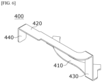
- FIG. 6 is a perspective view illustrating the second outer collector 400
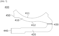
- FIG. 7 is a top plan view of the second outer collector 400.
- the second outer collector 400 includes a fourth region 410, a fifth region 420, a sixth region 430, and a second bent portion 440.
- the fourth region 410 is positioned at the second side of the stator 200.
- the fourth region 410 is disposed to overlap the stator 200 in the axial direction.
- the fourth region 410 is positioned at the second side of the stator 200.
- the stator 200 may be disposed between the fourth region 410 and the fifth region 420 in the axial direction.
- the fifth region 420 is disposed so as not to overlap the stator 200 in the axial direction.
- the sixth region 430 connects the fourth region 410 and the fifth region 420.
- the second bent portion 440 is bent from an end of the fifth region 420 toward the second side.
- the fourth region 410, the fifth region 420, the sixth region 430, and the second bent portion 440 have been described as being distinguished depending on functions, positions, and shapes thereof. However, the fourth region 410, the fifth region 420, the sixth region 430, and the second bent portion 440 may be connected to one another to define a single member.
- the fourth region 410 may be disposed on a plane perpendicular to the axial direction.
- the fourth region 410 may include an inner surface 411, an outer surface 412, and a second protruding portion 450.
- the inner surface 411 includes a curved surface. A center of curvature of the inner surface 411 may be consistent with an axial center of the sensor device.
- the outer surface 412 may also include a curved surface.
- the second protruding portion 450 protrudes outward in the direction perpendicular to the axial direction.
- the fifth region 420 may be disposed on a plane perpendicular to the axial direction.
- the fifth region 420 is disposed to be spaced apart from the fifth region 410 in the axial direction.
- the fourth region 410 and the fifth region 420 may be disposed so as not to overlap one another when viewed in the axial direction.
- the fourth region 410 is disposed to overlap the stator 200
- the fifth region 420 is disposed so as not to overlap the stator 200.
- the fifth region 420 is positioned outward of the fourth region 410 in the radial direction.
- the sixth region 430 connects one end of the fourth region 410 and one end of the fifth region 420.
- the second bent portion 440 is bent from the other end of the fifth region 420 so as to be directed toward the second side of the stator 200.
- FIG. 8 is a perspective view illustrating the first outer collector 300 and the first inner collector 500.
- the first inner collector 500 may include a seventh region 510, eighth regions 520, and ninth regions 530.
- the seventh region 510 is disposed on a plane perpendicular to the axial direction.
- the seventh region 510 is disposed to correspond to the second region 320.
- the seventh region 510 is disposed to overlap the second region 320 in the axial direction.
- the seventh region 510 may be disposed to be spaced apart from the second region 320 in the axial direction.
- the eighth regions 520 are bent from two opposite ends of the seventh region 510 toward the first side.
- the eighth region 520 may be disposed perpendicularly to the seventh region 510.
- the ninth region 530 is bent from the eighth region 520 in the direction perpendicular to the axial direction.
- the ninth region 530 is disposed on a plane perpendicular to the axial direction.
- the ninth region 530 is disposed to face the Hall sensor 700.
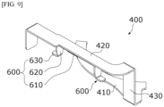
- FIG. 9 is a perspective view illustrating the second outer collector 400 and the second inner collector 600.
- the second inner collector 600 may include a tenth region 610, eleventh regions 620, and twelfth regions 630.
- the tenth region 610 is disposed on a plane perpendicular to the axial direction.
- the tenth region 610 is disposed to correspond to the fourth region 410.
- the tenth region 610 is disposed to overlap the fourth region 410 in the axial direction.
- the tenth region 610 may be disposed to be spaced apart from the fourth region 410 in the axial direction.
- the eleventh region 620 is bent from the tenth region 610 toward the second side.
- the eleventh region 620 may be disposed perpendicularly to the tenth region 610.
- the eleventh region 620 is bent from the tenth region 610 in the direction perpendicular to the axial direction.
- the twelfth region 630 is disposed on a plane perpendicular to the axial direction.
- the twelfth region 630 is disposed to face the Hall sensor 700.
- the first inner collector 500 and the second inner collector 600 may be disposed between the second region 320 and the fifth region 420 in the axial direction. Further, the second region 320, the fifth region 420, the first inner collector 500, and the second inner collector 600 may be disposed to overlap one another in the axial direction.
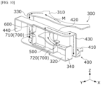
- FIG. 10 is a view illustrating a magnetic field M formed by the rotor and the stator 200.
- the magnetic field M formed by the rotor and the stator 200 flows through the first outer collector 300 and the first inner collector 500 toward the second outer collector 400.
- the magnetic field M formed by the rotor 100 and the stator 200 is collected in the first region 310 and flows through the third region 330 to the second region 320.
- the magnetic field M of the second region 320 flows to the first inner collector 500.
- a part of the magnetic field M of the first inner collector 500 flows to the Hall sensor 700, and another part of the magnetic field M is collected in the fifth region 420 of the second outer collector 400.
- the magnetic field M of the fifth region 420 flows through the sixth region 430 to the fourth region 410, and the magnetic field M flowing to the fourth region 410 flows to the stator 200.
- FIG. 11 is a view illustrating flows of external magnetic fields M1 and M2 applied in the axial direction.
- the external magnetic field M1 applied in the axial direction may be discharged to the outside through the first outer collector 300. Specifically, the external magnetic field M1 applied in the axial direction is collected in the first region 310 of the first outer collector 300. The external magnetic field M1 collected in the first region 310 flows through the third region 330 to the second region 320, and the external magnetic field M1 of the second region 320 is discharged to the outside.
- the external magnetic field M2 applied in the axial direction may be discharged to the outside through the second outer collector 400.
- the external magnetic field M2 applied in the axial direction is collected in the fourth region 410 of the second outer collector 400.
- the external magnetic field M2 collected in the fourth region 410 flows through the sixth region 430 to the fifth region 420, and the external magnetic field M2 of the fifth region 420 is discharged to the outside.
- the external magnetic fields M1 and M2 applied in the axial direction of the sensor device are discharged to the outside through the first outer collector 300 or the second outer collector 400 without affecting the Hall sensor 700, such that the change in sensing values caused by the external magnetic fields M1 and M2 may be minimized.
- first bent portion 340 may be disposed to overlap the Hall sensor 700 in the direction perpendicular to the axial direction. Further, the first bent portion 340 may be disposed to overlap the first inner collector 500 in the direction perpendicular to the axial direction.
- the second bent portion 440 may also be disposed to overlap the Hall sensor 700 in the direction perpendicular to the axial direction. Further, the second bent portion 440 may be disposed to overlap the second inner collector 600 in the direction perpendicular to the axial direction.
- FIG. 12 is a view illustrating flows of external magnetic fields M3 and M4 applied in the direction perpendicular to the axial direction.
- the external magnetic field M3 applied in the direction perpendicular to the axial direction may also be discharged to the outside through the first outer collector 300.
- the external magnetic field M3 applied in the direction perpendicular to the axial direction is collected in the first bent portion 340 of the first outer collector 300.
- the external magnetic field M3 collected in the first bent portion 340 flows through the second region 320 to the third region 330, and the external magnetic field M3 of the third region 330 is discharged to the outside in an intact manner.
- the external magnetic field M4 applied in the axial direction may be discharged to the outside through the second outer collector 400.
- the external magnetic field M4 applied in the axial direction is collected in the sixth region 430 of the second outer collector 400.
- the external magnetic field collected in the sixth region 430 flows through the sixth region 430 to the fifth region 420, and the external magnetic field M3 of the fifth region 420 flows to the second bent portion 440.
- the external magnetic field M3 of the second bent portion 440 is discharged to the outside.
- the external magnetic fields M3 and M4 applied in the direction perpendicular to the axial direction of the sensor device are discharged to the outside through the first outer collector 300 or the second outer collector 400 without affecting the Hall sensor 700, such that the change in sensing values caused by the external magnetic fields may be minimized.
- Table 1 shows the comparison between an offset of a sensing value according to an external magnetic field in a sensor device of a comparative example and an offset of a sensing value according to an external magnetic field in a sensor device according to an example.
- the comparative example is a sensor device including collectors distinguished and disposed at the first side and the second side of the stator 200, i.e., the sensor device including a collector integrated with a leg directed toward the Hall sensor 700.
- FIG. 13 is a view illustrating a state in which the first inner collector 500 and the second inner collector 600 are mounted on the housing 10.
- first inner collector 500 and the second inner collector 600 may be configured separately from the first outer collector 300 and the second outer collector 400 and easily assembled.
- the first inner collector 500 and the second inner collector 600 may be assembled to the housing 10 before the first outer collector 300 and the second outer collector 400 are assembled.
- the housing 10 may include a hole 10a into which the first inner collector 500 or the second inner collector 600 is inserted.
- the first inner collector 500 may be assembled toward the first side of the stator 200, and the second inner collector 600 may be assembled toward the second side of the stator 200.
- FIG. 14 is a view illustrating a state in which the first outer collector 300 and the second outer collector 400 are mounted on the housing 10
- FIG. 15 is a view illustrating a state in which the first outer collector 300 and the second outer collector 400 are mounted on the housing 10.
- the first outer collector 300 and the second outer collector 400 may be assembled to the housing 10 in the state in which the first inner collector 500 and the second inner collector 600 are assembled to the housing 10.
- the first outer collector 300 may be inserted into the housing 10 in the direction perpendicular to the axial direction so that the first outer collector 300 is aligned with the first inner collector 500.
- the second outer collector 400 may also be inserted into the housing 10 in the direction perpendicular to the axial direction so that the second outer collector 400 is aligned with the second inner collector 600.
- the assembling process is simplified.
- the above-mentioned embodiment may be used for various devices for vehicles or household appliances.
Landscapes
- Physics & Mathematics (AREA)
- General Physics & Mathematics (AREA)
- Engineering & Computer Science (AREA)
- Chemical & Material Sciences (AREA)
- Combustion & Propulsion (AREA)
- Transportation (AREA)
- Mechanical Engineering (AREA)
- Electromagnetism (AREA)
- Transmission And Conversion Of Sensor Element Output (AREA)
Abstract
An embodiment may provide a sensor device including a rotor, a stator disposed to correspond to the rotor, first and second outer collectors disposed at one side of the stator, first and second inner collectors disposed between the first and second outer collectors, and a Hall sensor disposed between the first inner collector and the second inner collector.
Description
- Embodiments relate to a sensor device.
- A power steering system (electronic power system (hereinafter, referred to as an 'EPS')) ensures turning stability and provides a quick restoring force by allowing an electronic control unit to operate a motor in accordance with a driving condition, thereby allowing a driver to perform safe driving.
- The EPS includes a sensor device configured to measure torque, a steering angle, and the like of a steering shaft in order to provide appropriate torque. The sensor device is a device that measures a degree of torsion of a torsion bar. The steering shaft includes an input shaft connected to a steering wheel, and an output shaft connected to a wheel side power transmission configuration, and the torsion bar is a member configured to connect the and input shaft and the output shaft.
- The sensor device includes a housing, a rotor, a stator including stator teeth, and a collector. In this case, the collector is disposed outside the stator teeth. For this reason, the collector serves as a passageway for an external magnetic field when the external magnetic field is formed, which causes a problem in that the collector affects a magnetic flux value of a sensor. When the sensor is affected by the collector, an output value of the sensor device changes, which causes a problem in that a degree of torsion of the torsion bar cannot be accurately measured.
- An object of an embodiment is to provide a sensor device capable of compensating for the amount of change in output value of a sensor caused by external magnetism.
- An embodiment may provide a sensor device including a rotor, a stator disposed to correspond to the rotor, first and second outer collectors disposed at one side of the stator, first and second inner collectors disposed between the first and second outer collectors, and a Hall sensor disposed between the first inner collector and the second inner collector.
- The first outer collector may include: a first region positioned at a first side of the stator in an axial direction; a second region positioned at a second side of the stator; and a third region configured to connect the first region and the second region, and the second outer collector may include: a fourth region positioned at the second side of the stator in the axial direction; a fifth region positioned at the first side of the stator; and a sixth region configured to connect the fourth region and the fifth region.
- The first inner collector and the second inner collector may be disposed between the second region and the fifth region.
- The first outer collector and the first inner collector may be disposed to be spaced apart from each other, and the second outer collector and the second inner collector may be disposed to be spaced apart from each other.
- The second region, the fifth region, the first inner collector, and the second inner collector may overlap one another in the axial direction.
- The second region may include a first bent portion bent toward the first side, and the first bent portion may be disposed to overlap the first inner collector in the direction perpendicular to the axial direction.
- The first bent portion may be disposed to overlap the Hall sensor in the direction perpendicular to the axial direction.
- The first region and the second region may be disposed on planes perpendicular to the axial direction, and the third region may be disposed perpendicularly to the first region and the second region.
- The fourth region and the fifth region may be disposed on planes perpendicular to the axial direction, and the sixth region may be disposed perpendicularly to the fourth region and the fifth region.
- The second region may include an inner surface and an outer surface, the inner surface may include a curved surface, and the outer surface may include a protruding portion protruding outward in the direction perpendicular to the axial direction.
- The fourth region may include an inner surface and an outer surface, the inner surface may include a curved surface, and the outer surface may include a second protruding portion protruding outward in a direction perpendicular to an axial center.
- The first inner collector may include a seventh region disposed to correspond to the second region, an eighth region bent from the seventh region toward the first side, and a ninth region bent from the eighth region in the direction perpendicular to the axial direction.
- The second inner collector may include a tenth region disposed to correspond to the fifth region, an eleventh region bent from the fifth region toward the second side, and a twelfth region bent from the eleventh region in the direction perpendicular to the axial direction.
- An embodiment may provide a sensor device including: a rotor; a stator disposed to correspond to the rotor; a first outer collector disposed at one side of the stator and configured to acquire a magnetic field from the stator; a first inner collector disposed to be spaced apart from the first outer collector and configured to acquire a magnetic field from the first outer collector; and a first Hall sensor unit disposed to acquire a magnetic field from the first inner collector.
- The first outer collector may be disposed to be spaced apart from the stator, and the first inner collector may be disposed to be spaced apart from the first outer collector.
- The magnetic field acquired from the stator may be transmitted to the first Hall sensor unit through the first outer collector and the first inner collector, and an external magnetic field in an axial direction may be collected at one side of the first outer collector based on the axial direction and discharged to the other side of the first outer collector.
- The first outer collector may include: a first region positioned at a first side of the stator in the axial direction; a second region positioned at a second side of the stator; and a third region configured to connect the first region and the second region, and the external magnetic field in the axial direction may be collected in the first region and discharged to the outside of the third region through the second region.
- An external magnetic field in a direction perpendicular to an axial direction may be collected at one side of the first outer collector based on the direction perpendicular to the axial direction and discharged to the other side of the first outer collector.
- The first outer collector may include a first region positioned at a first side of the stator in the axial direction, a second region positioned at a second side of the stator, and a third region configured to connect the first region and the second region, the second region may include a first bent portion bent toward the second side, and an external magnetic field in a direction perpendicular to the axial direction may be collected in the first bent portion.
- The sensor device may further include a second outer collector disposed at the other side of the stator and configured to acquire a magnetic field from the stator, a second inner collector disposed to be spaced apart from the second outer collector and configured to acquire a magnetic field from the second outer collector, and a second Hall sensor unit disposed to acquire a magnetic field from the first inner collector and the second inner collector.
- The second outer collector may be disposed to be spaced apart from the stator, and the second inner collector may be disposed to be spaced apart from the second outer collector.
- The magnetic field acquired from the stator may be transmitted to the first Hall sensor unit and the second Hall sensor unit through the second outer collector and the second inner collector, and an external magnetic field in an axial direction may be collected at one side of the second outer collector and discharged to the other side of the second outer collector.
- The second outer collector may include a fourth region positioned at the second side of the stator in the axial direction, a fifth region positioned at the first side of the stator, and a sixth region configured to connect the fourth region and the fifth region, and the external magnetic field in the axial direction may be collected in the sixth region and discharged to the outside of the fourth region through the fifth region.
- The external magnetic field in the direction perpendicular to the axial direction may be collected at one side of the second outer collector in the direction perpendicular to the axial direction and discharged to the other side of the second outer collector.
- The second outer collector may include a fourth region positioned at the second side of the stator in the axial direction, a fifth region positioned at the second side of the stator, and a sixth region configured to connect the fourth region and the fifth region, the fifth region may include a second bent portion bent toward the second side, and the external magnetic field in the direction perpendicular to the axial direction may be collected in the second bent portion.
- According to the embodiment, the outer collector serves as a shield against an external magnetic field, thereby reducing an influence of the external magnetic field on the Hall sensor.
- According to the embodiment, it is possible to prevent an external magnetic field, which is applied in the axial direction, and an external magnetic field, which is applied in the direction perpendicular to the axial direction, from affecting the Hall sensor.
- According to the embodiment, the outer collector and the inner collector are separated, such that an external magnetic field may flow more effectively.
- According to the embodiment, the outer collector and the inner collector are separated, such that the outer collector and the inner collector are easily assembled.
-
-
FIG. 1 is a perspective view illustrating a sensor device according to an embodiment. -
FIG. 2 is a view illustrating a rotor, a stator, and collectors of the sensor device illustrated inFIG. 1 . -
FIG. 3 is a perspective view illustrating a first outer collector and a second outer collector. -
FIG. 4 is a perspective view illustrating the first outer collector. -
FIG. 5 is a top plan view of the first outer collector. -
FIG. 6 is a perspective view illustrating the second outer collector. -
FIG. 7 is a top plan view of the second outer collector. -
FIG. 8 is a perspective view illustrating the first outer collector and a first inner collector. -
FIG. 9 is a perspective view illustrating the second outer collector and a second inner collector. -
FIG. 10 is a view illustrating a flow of magnetism generated by the rotor and the stator. -
FIG. 11 is a view illustrating a flow of an external magnetic field applied in an axial direction. -
FIG. 12 is a view illustrating a flow of an external magnetic field applied in a direction perpendicular to the axial direction. -
FIG. 13 is a view illustrating a state in which the first inner collector and the second inner collector are mounted on a housing. -
FIG. 14 is a view illustrating a state in which the first outer collector and the second outer collector are mounted on the housing. -
FIG. 15 is a view illustrating a state in which the first outer collector and the second outer collector are completely mounted on the housing. - Hereinafter, a direction perpendicular to an axial direction of a sensor device is referred to as a radial direction, and a direction in which a circle having a radius in the radial direction is defined about an axial center is referred to as a circumferential direction.
-
FIG. 1 is a perspective view illustrating a sensor device according to an embodiment, andFIG. 2 is a view illustrating arotor 100, astator 200, and collectors of the sensor device illustrated inFIG. 1 . - With reference to
FIGS. 1 and2 , the sensor device according to the embodiment may include therotor 100, thestator 200, a firstouter collector 300, a secondouter collector 400, a firstinner collector 500, a secondinner collector 600, and aHall sensor 700. In the drawings, an x-axis indicates a direction perpendicular to the axial direction, a y-axis indicates a direction perpendicular to the direction indicated by the x-axis and perpendicular to the axial direction, and a z-axis is the axial direction. - In this case, the
stator 200 may be connected to an output shaft (not illustrated), and therotor 100, which has at least a part rotatably disposed on thestator 200, may be connected to an input shaft (not illustrated). However, the present disclosure is not necessarily limited thereto. In this case, therotor 100 may be disposed to be rotatable relative to thestator 200. Hereinafter, the term 'inside' may mean a direction disposed toward the center based on the radial direction, and the term 'outside' may mean a direction opposite to the inside. - The
rotor 100 may include magnets. The magnet may be disposed inside thestator 200. The magnet may be connected to the input shaft through a separate holder. - A
housing 10 is disposed outside thestator 200. Thehousing 10 may include anupper housing 11 and alower housing 12. Thestator 200, the firstouter collector 300, the secondouter collector 400, the firstinner collector 500, and the secondinner collector 600 may be fixed to thehousing 10. - The first
outer collector 300 may be disposed in the axial direction from a first side toward a second side of thestator 200. The secondouter collector 400 may be disposed in the axial direction from the second side toward the first side of thestator 200. The first side refers to one side of thestator 200 based on the axial direction, and the second side refers to the other side of thestator 200 based on the axial direction. - The first
inner collector 500 and the secondinner collector 600 are disposed to correspond to theHall sensor 700. - The
Hall sensor 700 may include a firstHall sensor unit 710 and a secondHall sensor unit 720. - The first
Hall sensor unit 710 and the secondHall sensor unit 720 are disposed between the firstinner collector 500 and the secondinner collector 600 and detect a change in magnetic field generated between thestator 200 and therotor 100. The firstHall sensor unit 710 and the secondHall sensor unit 720 may each be a Hall IC. The sensor device measures torque on the basis of the detected change in the magnetic field. - The first
outer collector 300 and the secondouter collector 400 may be identical in shape and size and different in positions. The firstinner collector 500 and the secondinner collector 600 may also be identical in shape and size and different in positions. - The first
inner collector 500 and the secondinner collector 600 are positioned between the firstouter collector 300 and the secondouter collector 400 in the axial direction. Therefore, the firstinner collector 500 and the secondinner collector 600 are relatively less affected by the external magnetic field, which is applied in the axial direction, than the firstouter collector 300 and the secondouter collector 400. - The first
inner collector 500 may be disposed to be spaced apart from the first outer collector in the axial direction. Further, the secondinner collector 600 may be disposed to be spaced apart from the second outer collector in the axial direction. - The first
outer collector 300 or the secondouter collector 400 guides a flow of the magnetic field, which is generated between therotor 100 and thestator 200, to the firstinner collector 500 or the secondinner collector 600. In addition, the firstouter collector 300 or the secondouter collector 400 serves to guide the flow of the external magnetic field so that the external magnetic field is discharged to the outside without flowing to theHall sensor 700. - The first
inner collector 500 and the secondinner collector 600 serve to transmit the magnetic flow, which is generated between therotor 100 and thestator 200, to theHall sensor 700. -
FIG. 3 is a perspective view illustrating the firstouter collector 300 and the secondouter collector 400,FIG. 4 is a perspective view illustrating the firstouter collector 300, andFIG. 5 is a top plan view of the firstouter collector 300. - With reference to
FIGS. 3 and4 , the firstouter collector 300 includes afirst region 310, asecond region 320, athird region 330, and a firstbent portion 340. - The
first region 310 is positioned at the first side of thestator 200. Thefirst region 310 is disposed to overlap thestator 200 in the axial direction. Thesecond region 320 is positioned at the second side of thestator 200. Thestator 200 may be disposed between thefirst region 310 and thesecond region 320 in the axial direction. - The
second region 320 is disposed to overlap thestator 200 in the axial direction. Thethird region 330 connects thefirst region 310 and thesecond region 320. The firstbent portion 340 is bent from an end of thesecond region 320 toward the first side. - The
first region 310, thesecond region 320, thethird region 330, and the firstbent portion 340 have been described as being distinguished depending on functions, positions, and shapes thereof. However, thefirst region 310, thesecond region 320, thethird region 330, and the firstbent portion 340 may be connected to one another to define a single member. - The
first region 310 may be disposed on a plane perpendicular to the axial direction. Thefirst region 310 may include aninner surface 311, anouter surface 312, and a first protrudingportion 350. Theinner surface 311 includes a curved surface. A center of curvature of theinner surface 311 may be consistent with an axial center of the sensor device. Theouter surface 312 may also include a curved surface. The first protrudingportion 350 protrudes outward in the direction perpendicular to the axial direction. - The
second region 320 may be disposed on a plane perpendicular to the axial direction. Thesecond region 320 is disposed to be spaced apart from thefirst region 310 in the axial direction. - The
first region 310 and thesecond region 320 are disposed so as not to overlap each other when viewed in the axial direction. Thefirst region 310 is disposed to overlap thestator 200, but thesecond region 320 is disposed so as not to overlap thestator 200. Thesecond region 320 is positioned outward of thefirst region 310 in the radial direction. - The
third region 330 connects one end of thefirst region 310 and one end of thesecond region 320. - The first
bent portion 340 is bent from the other end of thesecond region 320 so as to be directed toward the first side of thestator 200. -
FIG. 6 is a perspective view illustrating the secondouter collector 400, andFIG. 7 is a top plan view of the secondouter collector 400. - With reference to
FIGS. 6 and7 , the secondouter collector 400 includes afourth region 410, afifth region 420, asixth region 430, and a secondbent portion 440. - The
fourth region 410 is positioned at the second side of thestator 200. Thefourth region 410 is disposed to overlap thestator 200 in the axial direction. Thefourth region 410 is positioned at the second side of thestator 200. Thestator 200 may be disposed between thefourth region 410 and thefifth region 420 in the axial direction. - The
fifth region 420 is disposed so as not to overlap thestator 200 in the axial direction. Thesixth region 430 connects thefourth region 410 and thefifth region 420. The secondbent portion 440 is bent from an end of thefifth region 420 toward the second side. - The
fourth region 410, thefifth region 420, thesixth region 430, and the secondbent portion 440 have been described as being distinguished depending on functions, positions, and shapes thereof. However, thefourth region 410, thefifth region 420, thesixth region 430, and the secondbent portion 440 may be connected to one another to define a single member. - The
fourth region 410 may be disposed on a plane perpendicular to the axial direction. Thefourth region 410 may include aninner surface 411, anouter surface 412, and a second protrudingportion 450. Theinner surface 411 includes a curved surface. A center of curvature of theinner surface 411 may be consistent with an axial center of the sensor device. Theouter surface 412 may also include a curved surface. The second protrudingportion 450 protrudes outward in the direction perpendicular to the axial direction. - The
fifth region 420 may be disposed on a plane perpendicular to the axial direction. Thefifth region 420 is disposed to be spaced apart from thefifth region 410 in the axial direction. - The
fourth region 410 and thefifth region 420 may be disposed so as not to overlap one another when viewed in the axial direction. Thefourth region 410 is disposed to overlap thestator 200, and thefifth region 420 is disposed so as not to overlap thestator 200. Thefifth region 420 is positioned outward of thefourth region 410 in the radial direction. - The
sixth region 430 connects one end of thefourth region 410 and one end of thefifth region 420. - The second
bent portion 440 is bent from the other end of thefifth region 420 so as to be directed toward the second side of thestator 200. -
FIG. 8 is a perspective view illustrating the firstouter collector 300 and the firstinner collector 500. - With reference to
FIG. 8 , the firstinner collector 500 may include aseventh region 510,eighth regions 520, andninth regions 530. - The
seventh region 510 is disposed on a plane perpendicular to the axial direction. Theseventh region 510 is disposed to correspond to thesecond region 320. Theseventh region 510 is disposed to overlap thesecond region 320 in the axial direction. Theseventh region 510 may be disposed to be spaced apart from thesecond region 320 in the axial direction. - The
eighth regions 520 are bent from two opposite ends of theseventh region 510 toward the first side. Theeighth region 520 may be disposed perpendicularly to theseventh region 510. Theninth region 530 is bent from theeighth region 520 in the direction perpendicular to the axial direction. Theninth region 530 is disposed on a plane perpendicular to the axial direction. Theninth region 530 is disposed to face theHall sensor 700. -
FIG. 9 is a perspective view illustrating the secondouter collector 400 and the secondinner collector 600. - With reference to
FIG. 9 , the secondinner collector 600 may include atenth region 610,eleventh regions 620, andtwelfth regions 630. - The
tenth region 610 is disposed on a plane perpendicular to the axial direction. Thetenth region 610 is disposed to correspond to thefourth region 410. Thetenth region 610 is disposed to overlap thefourth region 410 in the axial direction. Thetenth region 610 may be disposed to be spaced apart from thefourth region 410 in the axial direction. - The
eleventh region 620 is bent from thetenth region 610 toward the second side. Theeleventh region 620 may be disposed perpendicularly to thetenth region 610. Theeleventh region 620 is bent from thetenth region 610 in the direction perpendicular to the axial direction. Thetwelfth region 630 is disposed on a plane perpendicular to the axial direction. Thetwelfth region 630 is disposed to face theHall sensor 700. - The first
inner collector 500 and the secondinner collector 600 may be disposed between thesecond region 320 and thefifth region 420 in the axial direction. Further, thesecond region 320, thefifth region 420, the firstinner collector 500, and the secondinner collector 600 may be disposed to overlap one another in the axial direction. -
FIG. 10 is a view illustrating a magnetic field M formed by the rotor and thestator 200. - With reference to
FIG. 10 , the magnetic field M formed by the rotor and thestator 200 flows through the firstouter collector 300 and the firstinner collector 500 toward the secondouter collector 400. Specifically, the magnetic field M formed by therotor 100 and thestator 200 is collected in thefirst region 310 and flows through thethird region 330 to thesecond region 320. The magnetic field M of thesecond region 320 flows to the firstinner collector 500. A part of the magnetic field M of the firstinner collector 500 flows to theHall sensor 700, and another part of the magnetic field M is collected in thefifth region 420 of the secondouter collector 400. The magnetic field M of thefifth region 420 flows through thesixth region 430 to thefourth region 410, and the magnetic field M flowing to thefourth region 410 flows to thestator 200. -
FIG. 11 is a view illustrating flows of external magnetic fields M1 and M2 applied in the axial direction. - With reference to
FIG. 11 , the external magnetic field M1 applied in the axial direction may be discharged to the outside through the firstouter collector 300. Specifically, the external magnetic field M1 applied in the axial direction is collected in thefirst region 310 of the firstouter collector 300. The external magnetic field M1 collected in thefirst region 310 flows through thethird region 330 to thesecond region 320, and the external magnetic field M1 of thesecond region 320 is discharged to the outside. - In addition, the external magnetic field M2 applied in the axial direction may be discharged to the outside through the second
outer collector 400. Specifically, the external magnetic field M2 applied in the axial direction is collected in thefourth region 410 of the secondouter collector 400. The external magnetic field M2 collected in thefourth region 410 flows through thesixth region 430 to thefifth region 420, and the external magnetic field M2 of thefifth region 420 is discharged to the outside. - As described above, the external magnetic fields M1 and M2 applied in the axial direction of the sensor device are discharged to the outside through the first
outer collector 300 or the secondouter collector 400 without affecting theHall sensor 700, such that the change in sensing values caused by the external magnetic fields M1 and M2 may be minimized. - Meanwhile, the first
bent portion 340 may be disposed to overlap theHall sensor 700 in the direction perpendicular to the axial direction. Further, the firstbent portion 340 may be disposed to overlap the firstinner collector 500 in the direction perpendicular to the axial direction. - The second
bent portion 440 may also be disposed to overlap theHall sensor 700 in the direction perpendicular to the axial direction. Further, the secondbent portion 440 may be disposed to overlap the secondinner collector 600 in the direction perpendicular to the axial direction. - This is to allow the first
bent portion 340 or the secondbent portion 440 to collect the external magnetic field applied in the direction perpendicular to the axial direction, thereby preventing the external magnetic field from affecting theHall sensor 700. -
FIG. 12 is a view illustrating flows of external magnetic fields M3 and M4 applied in the direction perpendicular to the axial direction. - With reference to
FIG. 12 , the external magnetic field M3 applied in the direction perpendicular to the axial direction may also be discharged to the outside through the firstouter collector 300. Specifically, the external magnetic field M3 applied in the direction perpendicular to the axial direction is collected in the firstbent portion 340 of the firstouter collector 300. The external magnetic field M3 collected in the firstbent portion 340 flows through thesecond region 320 to thethird region 330, and the external magnetic field M3 of thethird region 330 is discharged to the outside in an intact manner. - In addition, the external magnetic field M4 applied in the axial direction may be discharged to the outside through the second
outer collector 400. Specifically, the external magnetic field M4 applied in the axial direction is collected in thesixth region 430 of the secondouter collector 400. The external magnetic field collected in thesixth region 430 flows through thesixth region 430 to thefifth region 420, and the external magnetic field M3 of thefifth region 420 flows to the secondbent portion 440. The external magnetic field M3 of the secondbent portion 440 is discharged to the outside. - As described above, the external magnetic fields M3 and M4 applied in the direction perpendicular to the axial direction of the sensor device are discharged to the outside through the first
outer collector 300 or the secondouter collector 400 without affecting theHall sensor 700, such that the change in sensing values caused by the external magnetic fields may be minimized. - Table 1 below shows the comparison between an offset of a sensing value according to an external magnetic field in a sensor device of a comparative example and an offset of a sensing value according to an external magnetic field in a sensor device according to an example.
- In this case, the comparative example is a sensor device including collectors distinguished and disposed at the first side and the second side of the
stator 200, i.e., the sensor device including a collector integrated with a leg directed toward theHall sensor 700. - As shown in Table 1, it can be ascertained that in the case of the external magnetic fields applied in the directions (the first direction (x) and the second direction (y)) perpendicular to the axial direction, the offset of the sensing value of the comparative example and the offset of the sensing value of the embodiment are almost equal to each other. However, it can be ascertained that in the case of the external magnetic field applied in the axial direction, the offset of the sensor device according to the example is as very low as 1/10 of the offset of the sensing value of the comparative example, the influence of the external magnetic field applied in the axial direction is relatively smaller in the example than in the comparative example.
<Table 1> Comparative Example Example Offset (deg) of sensing value corresponding to external magnetic field First direction (x) 0.00 deg 0.00 deg Second direction (y) 0.02 deg 0.02 deg Axial direction (z) 0.40 deg 0.04 deg -
FIG. 13 is a view illustrating a state in which the firstinner collector 500 and the secondinner collector 600 are mounted on thehousing 10. - With reference to
FIG. 13 , the firstinner collector 500 and the secondinner collector 600 may be configured separately from the firstouter collector 300 and the secondouter collector 400 and easily assembled. - During a process of assembling the sensor device, the first
inner collector 500 and the secondinner collector 600 may be assembled to thehousing 10 before the firstouter collector 300 and the secondouter collector 400 are assembled. Thehousing 10 may include ahole 10a into which the firstinner collector 500 or the secondinner collector 600 is inserted. The firstinner collector 500 may be assembled toward the first side of thestator 200, and the secondinner collector 600 may be assembled toward the second side of thestator 200. -
FIG. 14 is a view illustrating a state in which the firstouter collector 300 and the secondouter collector 400 are mounted on thehousing 10, andFIG. 15 is a view illustrating a state in which the firstouter collector 300 and the secondouter collector 400 are mounted on thehousing 10. - With reference to
FIGS. 14 and15 , the firstouter collector 300 and the secondouter collector 400 may be assembled to thehousing 10 in the state in which the firstinner collector 500 and the secondinner collector 600 are assembled to thehousing 10. The firstouter collector 300 may be inserted into thehousing 10 in the direction perpendicular to the axial direction so that the firstouter collector 300 is aligned with the firstinner collector 500. The secondouter collector 400 may also be inserted into thehousing 10 in the direction perpendicular to the axial direction so that the secondouter collector 400 is aligned with the secondinner collector 600. - As described above, because the first
outer collector 300 and the secondouter collector 400 are separated from the firstinner collector 500 and the secondinner collector 600 and assembled to the firstinner collector 500 and the secondinner collector 600, the assembling process is simplified. - The above-mentioned embodiment may be used for various devices for vehicles or household appliances.
Claims (10)
- A sensor device comprising:a rotor;a stator disposed to correspond to the rotor;first and second outer collectors disposed at one side of the stator;first and second inner collectors disposed between the first and second outer collectors; anda Hall sensor disposed between the first inner collector and the second inner collector.
- The sensor device of claim 1, wherein the first outer collector comprises:a first region positioned at a first side of the stator in an axial direction;a second region positioned at a second side of the stator; anda third region configured to connect the first region and the second region, andwherein the second outer collector comprises:a fourth region positioned at the second side of the stator in the axial direction;a fifth region positioned at the first side of the stator; anda sixth region configured to connect the fourth region and the fifth region.
- The sensor device of claim 2, wherein the first inner collector and the second inner collector are disposed between the second region and the fifth region.
- The sensor device of claim 1, wherein the first outer collector and the first inner collector are disposed to be spaced apart from each other, and the second outer collector and the second inner collector are disposed to be spaced apart from each other.
- The sensor device of claim 2, wherein the second region, the fifth region, the first inner collector, and the second inner collector overlap one another in the axial direction.
- A sensor device comprising:a rotor;a stator disposed to correspond to the rotor;a first outer collector disposed at one side of the stator and configured to acquire a magnetic field from the stator;a first inner collector disposed to be spaced apart from the first outer collector and configured to acquire a magnetic field from the first outer collector; anda first Hall sensor unit disposed to acquire a magnetic field from the first inner collector.
- The sensor device of claim 6, wherein the first outer collector is disposed to be spaced apart from the stator, and the first inner collector is disposed to be spaced apart from the first outer collector.
- The sensor device of claim 6, wherein the magnetic field acquired from the stator is transmitted to the first Hall sensor unit through the first outer collector and the first inner collector, and
wherein an external magnetic field in an axial direction is collected at one side of the first outer collector based on the axial direction and discharged to the other side of the first outer collector. - The sensor device of claim 8, wherein the first outer collector comprises:a first region positioned at a first side of the stator in the axial direction;a second region positioned at a second side of the stator; anda third region configured to connect the first region and the second region, andwherein the external magnetic field in the axial direction is collected in the first region and discharged to the outside of the third region through the second region.
- The sensor device of claim 6, wherein an external magnetic field in a direction perpendicular to an axial direction is collected at one side of the first outer collector based on the direction perpendicular to the axial direction and discharged to the other side of the first outer collector.
Applications Claiming Priority (2)
| Application Number | Priority Date | Filing Date | Title |
|---|---|---|---|
| KR1020220072143A KR20230171683A (en) | 2022-06-14 | 2022-06-14 | Apparatus for sensing |
| PCT/KR2023/008188 WO2023244009A1 (en) | 2022-06-14 | 2023-06-14 | Sensor device |
Publications (1)
| Publication Number | Publication Date |
|---|---|
| EP4542175A1 true EP4542175A1 (en) | 2025-04-23 |
Family
ID=89191637
Family Applications (1)
| Application Number | Title | Priority Date | Filing Date |
|---|---|---|---|
| EP23824223.4A Pending EP4542175A1 (en) | 2022-06-14 | 2023-06-14 | Sensor device |
Country Status (4)
| Country | Link |
|---|---|
| EP (1) | EP4542175A1 (en) |
| KR (1) | KR20230171683A (en) |
| CN (1) | CN119365755A (en) |
| WO (1) | WO2023244009A1 (en) |
Family Cites Families (5)
| Publication number | Priority date | Publication date | Assignee | Title |
|---|---|---|---|---|
| DE10316124A1 (en) * | 2003-04-04 | 2004-10-28 | Valeo Schalter Und Sensoren Gmbh | Device for determining a torque exerted on a shaft |
| US9347843B2 (en) * | 2014-08-28 | 2016-05-24 | Bourns, Inc. | Low-height sensor for measuring torque angle |
| DE102018119807A1 (en) * | 2018-08-15 | 2020-02-20 | Valeo Schalter Und Sensoren Gmbh | Torque sensor device, method for determining a torque, stator and stator arrangement |
| FR3093182B1 (en) * | 2019-02-25 | 2021-05-07 | Moving Magnet Tech | Position sensor, in particular intended for detecting the torsion of a steering column |
| EP4242616B1 (en) * | 2020-08-26 | 2025-04-02 | Valeo Schalter und Sensoren GmbH | Torque sensor device, flux guide assembly, and flux guide |
-
2022
- 2022-06-14 KR KR1020220072143A patent/KR20230171683A/en active Pending
-
2023
- 2023-06-14 WO PCT/KR2023/008188 patent/WO2023244009A1/en not_active Ceased
- 2023-06-14 CN CN202380046599.XA patent/CN119365755A/en active Pending
- 2023-06-14 EP EP23824223.4A patent/EP4542175A1/en active Pending
Also Published As
| Publication number | Publication date |
|---|---|
| CN119365755A (en) | 2025-01-24 |
| KR20230171683A (en) | 2023-12-21 |
| WO2023244009A1 (en) | 2023-12-21 |
Similar Documents
| Publication | Publication Date | Title |
|---|---|---|
| US7089809B2 (en) | Torque sensor and electric power steering system having same | |
| JP3874642B2 (en) | Torque sensor and electric power steering apparatus provided with the torque sensor | |
| US8448528B2 (en) | Three-piece torque sensor assembly | |
| US20150090051A1 (en) | Torque Index Sensor | |
| US11035745B2 (en) | Torque sensor | |
| US11448523B2 (en) | Sensor device having a rotor that includes a sleeve and a magnet | |
| EP4542175A1 (en) | Sensor device | |
| US20240255310A1 (en) | Sensing apparatus | |
| EP3842777A1 (en) | Sensing device | |
| EP3940358B1 (en) | Sensing device | |
| KR20240039322A (en) | Apparatus for sensing | |
| US11719587B2 (en) | Sensing device | |
| US20230038153A1 (en) | Sensing device | |
| US12442661B2 (en) | Sensing device | |
| US20240383530A1 (en) | Sensing device | |
| KR20240098713A (en) | Apparatus for sensing | |
| KR20240020641A (en) | Apparatus for sensing | |
| US12546630B2 (en) | Sensing device | |
| KR20240103429A (en) | Apparatus for sensing | |
| EP4571262A1 (en) | Sensor device | |
| KR20240100636A (en) | Apparatus for sensing | |
| KR20190073878A (en) | Apparatus for sensing | |
| KR20190086149A (en) | Roating sensing apparatus | |
| JP2002350179A (en) | Rotation detection device |
Legal Events
| Date | Code | Title | Description |
|---|---|---|---|
| STAA | Information on the status of an ep patent application or granted ep patent |
Free format text: STATUS: THE INTERNATIONAL PUBLICATION HAS BEEN MADE |
|
| PUAI | Public reference made under article 153(3) epc to a published international application that has entered the european phase |
Free format text: ORIGINAL CODE: 0009012 |
|
| STAA | Information on the status of an ep patent application or granted ep patent |
Free format text: STATUS: REQUEST FOR EXAMINATION WAS MADE |
|
| 17P | Request for examination filed |
Effective date: 20241122 |
|
| AK | Designated contracting states |
Kind code of ref document: A1 Designated state(s): AL AT BE BG CH CY CZ DE DK EE ES FI FR GB GR HR HU IE IS IT LI LT LU LV MC ME MK MT NL NO PL PT RO RS SE SI SK SM TR |
|
| DAV | Request for validation of the european patent (deleted) | ||
| DAX | Request for extension of the european patent (deleted) |