EP4542162A1 - Microchannel heat exchanger and a fluid distributor thereof - Google Patents
Microchannel heat exchanger and a fluid distributor thereof Download PDFInfo
- Publication number
- EP4542162A1 EP4542162A1 EP24205547.3A EP24205547A EP4542162A1 EP 4542162 A1 EP4542162 A1 EP 4542162A1 EP 24205547 A EP24205547 A EP 24205547A EP 4542162 A1 EP4542162 A1 EP 4542162A1
- Authority
- EP
- European Patent Office
- Prior art keywords
- housing
- base
- distributor
- heat exchanger
- circular base
- Prior art date
- Legal status (The legal status is an assumption and is not a legal conclusion. Google has not performed a legal analysis and makes no representation as to the accuracy of the status listed.)
- Pending
Links
Images



Classifications
-
- F—MECHANICAL ENGINEERING; LIGHTING; HEATING; WEAPONS; BLASTING
- F28—HEAT EXCHANGE IN GENERAL
- F28D—HEAT-EXCHANGE APPARATUS, NOT PROVIDED FOR IN ANOTHER SUBCLASS, IN WHICH THE HEAT-EXCHANGE MEDIA DO NOT COME INTO DIRECT CONTACT
- F28D1/00—Heat-exchange apparatus having stationary conduit assemblies for one heat-exchange medium only, the media being in contact with different sides of the conduit wall, in which the other heat-exchange medium is a large body of fluid, e.g. domestic or motor car radiators
- F28D1/02—Heat-exchange apparatus having stationary conduit assemblies for one heat-exchange medium only, the media being in contact with different sides of the conduit wall, in which the other heat-exchange medium is a large body of fluid, e.g. domestic or motor car radiators with heat-exchange conduits immersed in the body of fluid
- F28D1/04—Heat-exchange apparatus having stationary conduit assemblies for one heat-exchange medium only, the media being in contact with different sides of the conduit wall, in which the other heat-exchange medium is a large body of fluid, e.g. domestic or motor car radiators with heat-exchange conduits immersed in the body of fluid with tubular conduits
- F28D1/053—Heat-exchange apparatus having stationary conduit assemblies for one heat-exchange medium only, the media being in contact with different sides of the conduit wall, in which the other heat-exchange medium is a large body of fluid, e.g. domestic or motor car radiators with heat-exchange conduits immersed in the body of fluid with tubular conduits the conduits being straight
- F28D1/0535—Heat-exchange apparatus having stationary conduit assemblies for one heat-exchange medium only, the media being in contact with different sides of the conduit wall, in which the other heat-exchange medium is a large body of fluid, e.g. domestic or motor car radiators with heat-exchange conduits immersed in the body of fluid with tubular conduits the conduits being straight the conduits having a non-circular cross-section
- F28D1/05366—Assemblies of conduits connected to common headers, e.g. core type radiators
- F28D1/05383—Assemblies of conduits connected to common headers, e.g. core type radiators with multiple rows of conduits or with multi-channel conduits
-
- F—MECHANICAL ENGINEERING; LIGHTING; HEATING; WEAPONS; BLASTING
- F28—HEAT EXCHANGE IN GENERAL
- F28F—DETAILS OF HEAT-EXCHANGE AND HEAT-TRANSFER APPARATUS, OF GENERAL APPLICATION
- F28F9/00—Casings; Header boxes; Auxiliary supports for elements; Auxiliary members within casings
- F28F9/22—Arrangements for directing heat-exchange media into successive compartments, e.g. arrangements of guide plates
-
- F—MECHANICAL ENGINEERING; LIGHTING; HEATING; WEAPONS; BLASTING
- F28—HEAT EXCHANGE IN GENERAL
- F28D—HEAT-EXCHANGE APPARATUS, NOT PROVIDED FOR IN ANOTHER SUBCLASS, IN WHICH THE HEAT-EXCHANGE MEDIA DO NOT COME INTO DIRECT CONTACT
- F28D21/00—Heat-exchange apparatus not covered by any of the groups F28D1/00 - F28D20/00
-
- F—MECHANICAL ENGINEERING; LIGHTING; HEATING; WEAPONS; BLASTING
- F25—REFRIGERATION OR COOLING; COMBINED HEATING AND REFRIGERATION SYSTEMS; HEAT PUMP SYSTEMS; MANUFACTURE OR STORAGE OF ICE; LIQUEFACTION SOLIDIFICATION OF GASES
- F25B—REFRIGERATION MACHINES, PLANTS OR SYSTEMS; COMBINED HEATING AND REFRIGERATION SYSTEMS; HEAT PUMP SYSTEMS
- F25B39/00—Evaporators; Condensers
-
- F—MECHANICAL ENGINEERING; LIGHTING; HEATING; WEAPONS; BLASTING
- F25—REFRIGERATION OR COOLING; COMBINED HEATING AND REFRIGERATION SYSTEMS; HEAT PUMP SYSTEMS; MANUFACTURE OR STORAGE OF ICE; LIQUEFACTION SOLIDIFICATION OF GASES
- F25B—REFRIGERATION MACHINES, PLANTS OR SYSTEMS; COMBINED HEATING AND REFRIGERATION SYSTEMS; HEAT PUMP SYSTEMS
- F25B39/00—Evaporators; Condensers
- F25B39/02—Evaporators
- F25B39/028—Evaporators having distributing means
-
- F—MECHANICAL ENGINEERING; LIGHTING; HEATING; WEAPONS; BLASTING
- F28—HEAT EXCHANGE IN GENERAL
- F28F—DETAILS OF HEAT-EXCHANGE AND HEAT-TRANSFER APPARATUS, OF GENERAL APPLICATION
- F28F1/00—Tubular elements; Assemblies of tubular elements
- F28F1/02—Tubular elements of cross-section which is non-circular
-
- F—MECHANICAL ENGINEERING; LIGHTING; HEATING; WEAPONS; BLASTING
- F28—HEAT EXCHANGE IN GENERAL
- F28F—DETAILS OF HEAT-EXCHANGE AND HEAT-TRANSFER APPARATUS, OF GENERAL APPLICATION
- F28F9/00—Casings; Header boxes; Auxiliary supports for elements; Auxiliary members within casings
-
- F—MECHANICAL ENGINEERING; LIGHTING; HEATING; WEAPONS; BLASTING
- F28—HEAT EXCHANGE IN GENERAL
- F28F—DETAILS OF HEAT-EXCHANGE AND HEAT-TRANSFER APPARATUS, OF GENERAL APPLICATION
- F28F9/00—Casings; Header boxes; Auxiliary supports for elements; Auxiliary members within casings
- F28F9/02—Header boxes; End plates
- F28F9/026—Header boxes; End plates with static flow control means, e.g. with means for uniformly distributing heat exchange media into conduits
- F28F9/027—Header boxes; End plates with static flow control means, e.g. with means for uniformly distributing heat exchange media into conduits in the form of distribution pipes
- F28F9/0275—Header boxes; End plates with static flow control means, e.g. with means for uniformly distributing heat exchange media into conduits in the form of distribution pipes with multiple branch pipes
-
- F—MECHANICAL ENGINEERING; LIGHTING; HEATING; WEAPONS; BLASTING
- F28—HEAT EXCHANGE IN GENERAL
- F28F—DETAILS OF HEAT-EXCHANGE AND HEAT-TRANSFER APPARATUS, OF GENERAL APPLICATION
- F28F2260/00—Heat exchangers or heat exchange elements having special size, e.g. microstructures
- F28F2260/02—Heat exchangers or heat exchange elements having special size, e.g. microstructures having microchannels
Definitions
- This invention relates to the field of heat exchangers, and more particularly, a heat exchanger, and a low-volume fluid distributor for heat exchangers.
- a heat exchanger comprising a distributor that comprises a housing of a predefined shape.
- the heat exchanger further comprises a plurality of microchannel tubes, wherein an inlet end of the plurality of microchannel tubes is bundled in one or more groups, and wherein the inlet end of the one or more bundled groups is fluidically disposed within the housing of the distributor through one or more sides and/or one or more surfaces of the housing of the distributor.
- the housing of the distributor is a hollow cylindrical member comprising a first circular base, a second circular base parallel to the first circular base, and a curved lateral surface connecting perimeters of the first circular base and the second circular base, wherein the one or more bundled groups are fluidically disposed within the housing, from one or more directions, through one or more of the first base, the second base, and/or the curved lateral surface, and wherein the heat exchanger further comprises a feeder tube fluidically connected to any of the first circular base, the second circular base, or the curved lateral surface.
- the housing of the distributor is a hollow member having a polyhedral shape and comprising a first base, a second base parallel to the first base, and a plurality of planar lateral sides connecting perimeters of the first base and the second base, wherein the one or more bundled groups are fluidically disposed within the housing, from one or more directions, through one or more of the first base, the second base, and/or the planar lateral sides, and wherein the heat exchanger further comprises a feeder tube fluidically connected to any of the first base, the second base, or any of the planar lateral sides.
- the housing of the distributor has a conical profile comprising a circular base, and a curved lateral surface extending from a vortex end to the circular base, wherein the distributor comprises an inlet at the vortex end, and a plurality of outlets configured circumferentially around the circular base and in fluidic communication with the inlet via a plurality of fluidic passages extending within the housing.
- the inlet end of the microchannel tubes associated with each of the bundled groups are profiled in a curved shape, wherein the curved microchannel tubes are disposed within the circular base of the housing through the plurality of outlets, and wherein the heat exchanger further comprises a feeder tube fluidically connected to the inlet of the housing.
- the feeder tube is configured off-centered from a central longitudinal axis of the housing.
- the heat exchanger comprises a flow disrupter configured within the housing of the distributor.
- the heat exchanger further comprises a collector, wherein an outlet end of the plurality of microchannel tubes is bundled in one or more groups, wherein the one or more bundled groups of the outlet end of the microchannel tubes are fluidically disposed within the collector through one or more sides and/or one or more surfaces of the collector.
- a length, between the inlet end and the outlet end, of the plurality of microchannel tubes is configured in a predefined configuration having a predefined number of turns or a predefined number of passes.
- the heat exchanger comprises one or more distributors, each comprising a housing of a predefined shape, and a plurality of microchannel tubes, wherein an inlet end of the plurality of microchannel tubes is bundled in one or more first groups, wherein the inlet end of at least one of the bundled first groups is fluidically disposed within the housing associated with one of the distributors through one or more sides and/or one or more surfaces of the corresponding housing.
- the heat exchanger further comprises one or more collectors, wherein an outlet end of the plurality of microchannel tubes is bundled in one or more second groups, wherein the outlet end of at least one of the bundled second groups is fluidically disposed within one of the collectors through one or more sides or one or more surfaces of the corresponding collector.
- a length, between the inlet end and the outlet end, of the plurality of microchannel tubes is configured in a predefined configuration having a predefined number of turns or a predefined number of passes.
- a fluid distributor for a heat exchanger comprising a housing comprising one or more sides and/or one or more surfaces defining a predefined shape and a predefined internal volume, wherein a first end of a plurality of microchannel tubes associated with the heat exchanger are bundled in one or more groups, and wherein the distributor is configured to fluidically accommodate the first end of the one or more bundled groups through the one or more sides and/or the one or more surfaces of the housing.
- the housing is a hollow cylindrical member that comprises a first circular base, a second circular base parallel to the first circular base, and a curved lateral surface connecting perimeters of the first circular base, and the second circular base, wherein the one or more bundled groups are fluidically disposed within the housing, from one or more directions, through one or more of the first circular base, the second circular, and/or the curved lateral surface, and wherein any of the first circular base, the second circular base, or the curved lateral surface of the distributor is configured to fluidically accommodate a feeder tube associated with the heat exchanger.
- the housing is a hollow member having a polyhedral shape that comprises a first base, a second base parallel to the first base, and a plurality of planar lateral sides connecting perimeters of the first base, and the second base, wherein the one or more bundled groups are fluidically disposed within the housing, from one or more directions, through one or more of the first base, the second base, and/or the planar lateral sides, and wherein any of the first base, the second base, or any of the planar lateral sides of the distributor is configured to fluidically accommodate a feeder tube associated with the heat exchanger.
- the housing is a hollow member of the predefined shape being defined by a combination of one or more planar sides and one or more curved surfaces, wherein the one or more bundled groups are fluidically disposed within the housing, from one or more directions, through one or more of the planar sides, and the curved sides, and wherein any of the planar sides, or any of the curved sides of the distributor is configured to fluidically accommodate a feeder tube associated with the heat exchanger.
- the housing has a solid conical profile that comprises a circular base, and a curved lateral surface extending from a vortex end to a circular base, wherein the distributor comprises an inlet at the vortex end, and a plurality of outlets configured circumferentially around the circular base and in fluidic communication with the inlet via a plurality of fluidic passages.
- the first end of the microchannel tubes associated with each of the bundled groups are profiled in a curved shape, wherein the curved microchannel tubes are disposed within the circular base of the housing through the plurality of outlets, and wherein the inlet of the housing is configured to fluidically accommodate a feeder tube associated with the heat exchanger.
- the feeder tube is configured off-centered from a central longitudinal axis of the housing.
- the heat exchanger comprises a flow disrupter configured within the housing of the distributor.
- Microchannel heat exchangers employing microchannel tubes are crucial components in heat pump systems, facilitating efficient heat transfer between different fluid streams. These heat exchangers are employed in a wide range of applications, including residential and commercial heating, ventilation, and air conditioning (HVAC) systems.
- Conventional MCHX has relatively large volume headers on both sides of the microchannel tubes or heat exchange section in order to distribute the flow into the tubes and collect the flow leaving the tubes.
- These headers can be horizontal or vertical header in the form of a cylindrical tube extending along an entire length of the heat exchange section of the MCHX, with individual MCHX tubes spaced by some distance and disposed along a length of the header.
- These larger volume headers can contribute to increased refrigerant volume requirements, which can result in elevated costs and safety concerns when handling flammable refrigerants.
- the high number of connections on conventional headers escalates the risk of potential failure points, impacting reliability and maintenance efforts.
- the heat exchanger 100 can include a distributor 102, a collector 104, and a plurality of microchannel tubes 106 extending between the distributor 102 and the collector 104.
- the inlet end of the microchannel tubes 106 can be bundled in one or more groups (first groups) that can be fluidically disposed within (embedded) the distributor 102 through one or more sides and/or one or more surfaces of the distributor 102.
- the heat exchanger 100 can further include a feeder tube 110 fluidically connected to an inlet side of the distributor 102 to supply the fluid into the bundled microchannel tubes 106 through the distributor 102.
- the detailed construction of the distributor 102 has been described later in conjunction with FIGs. 2A to 6D .
- the outlet end of the microchannel tubes 106 can also be bundled in one or more groups (second groups) that can be fluidically disposed within the collector 104 through one or more sides and/or one or more surfaces of the collector 104.
- the outlet end of the microchannel tubes 106 can also be directly fluidically disposed within the collector 104.
- a length, between the inlet end and the outlet end, of the microchannel tubes 106 may form a heat exchange section that can be configured in a predefined configuration having a predefined number of turns, a predefined number of passes, or both.
- the microchannel tubes 106 or heat exchange section can facilitate heat exchange between a fluid (refrigerant) flowing through the tubes 106 and another fluid (air) flowing across the heat exchange section.
- the heat exchanger 100 or heat exchange section can include a plurality of heat-dissipating fins configured between the microchannel tubes 106 to increase the exchange/transfer area of the tubes 106 and correspondingly enhance the heat exchange.
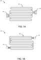
- the tubes 106 can be configured in a serpentine configuration having a predefined number of passes and turns in each of the separated circuits as shown in FIG. 1A , the integrated circuits as shown in FIG. 1B or combinations thereof.
- the length, between the inlet end and the outlet end, of each of the individual microchannel tubes 106 can have a predefined number of passes and turns, which extend separately from other microchannel tubes 106.
- Each of the separated circuits may have the same or different length.
- Each of the separated circuits may have the same or different number of passes or turns.
- the length, between the inlet end and the outlet end, of the microchannel tubes 106 can extend substantially parallel with each other while having a predefined number of passes and turns.
- the heat exchanger 100 can include one or more distributors 102-1 to 102-3, one or more collectors 104-1 to 104-3, and the plurality of microchannel tubes 106-A to 106-C fluidically connected and extending between the distributors 102-1 to 102-3, and the collectors 104-1 to 104-3.
- the inlet end of the microchannel tubes 106-A to 106-C can be bundled in one or more first groups and the outlet inlet end of the microchannel tubes 106-A to 106-C can be further bundled in one or more second groups.
- the inlet end of at least one of the bundled first groups can be fluidically disposed within one of the distributors 102-1 to 102-3 through one or more sides and/or one or more surfaces of the corresponding housing of the distributors 102-1 to 102-3.
- the outlet end of at least one of the bundled second groups of the tubes 106-A to 106-C can be fluidically disposed within one of the collectors 104-1 to 104-3 through one or more sides or one or more surfaces of the corresponding collector.
- the outlet end of the microchannel tubes 106-A to 106-C may not be bundled in groups and can be directly fluidically disposed within one of the collectors through one or more sides or one or more surfaces of the corresponding collector 104.
- the heat exchanger 100 can include a single collector 104, where the outlet end of the microchannel tubes 106 may not be bundled in groups and can be directly fluidically disposed within the collector 104 through one or more sides or one or more surfaces of the corresponding collector 104.
- an inlet side of each of the distributors 102-1 to 102-3 can be fluidically connected to a common distributor 108.
- the common distributor 108 can be fluidically connected to a feeder tube 110 associated with the heat exchanger 100.
- the common distributor 108 can supply an equal volume of fluid (received from the feeder tube 110) to each of the distributors 102-1 to 102-3.
- an outlet side of each of the collectors 104-1 to 104-3 can be further fluidically connected to a common collector line to receive the fluid from each of the collectors 104-1 to 104-3.
- the length, between the inlet end and the outlet end, of the plurality of microchannel tubes 106 can be configured in a predefined configuration having a predefined number of turns or a predefined number of passes to form the heat exchange section.
- the heat exchanger 100 or heat exchange section can include a plurality of heat-dissipating fins configured between the microchannel tubes 106 to increase the exchange/transfer area of the tubes 106 and correspondingly enhance the heat exchange.
- the distributor 102 can include a housing comprising one or more sides and/or one or more surfaces defining a predefined shape and a predefined internal volume.
- the distributor 102 can be configured to fluidically accommodate the first end (inlet end) of the bundled groups of the microchannel tubes 106 through one or more sides and/or one or more surfaces of the housing.
- the distributor 102 can be further configured to fluidically accommodate the feeder tube 110 associated with the heat exchanger, either radially or axially, from any of the sides or surfaces of the housing of the distributor 102.
- the first end of the microchannel tubes 106 can be stacked or bundled vertically, horizontally, or in other configurations. Further, a portion of a wall associated with the corresponding sides and/or surfaces of the housing can be removed and the first end of the bundled group 106 can be embedded within the housing through the removed portion and the feeder tube 110 can be connected to an inlet of the housing. Further, the embedded bundled groups 106 can be brazed along with the housing to fluidically seal the distributor 102 such that the fluid can flow from the feeder tube 110 into the bundled groups of the microchannel tubes 106 via the housing without any leakage.
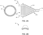
- the housing 202 of the distributor 102 can have a solid conical profile comprising a circular base 202-1, and a curved lateral surface 202-3 extending from a vortex end 202-2 to the circular base 202-1.
- the distributor 102 can include an inlet 204 at the vortex end 202-2 and a plurality of outlets 206 configured circumferentially around the circular base 202-1 and in fluidic communication with the inlet 204 via a plurality of fluidic passages.
- the first end of the microchannel tubes 106 associated with each of the bundled groups can be profiled in a curved shape based on the profile of the circular base 202-1 of the distributor 102.
- the curved microchannel tubes 106 can be disposed within the circular base 202-1 of the housing 202 through the plurality of outlets 206. Further, the feeder tube 110 can be fluidically connected to the inlet 204 of the housing 202 such that the distributor 102 can radially supply the fluid received from the feeder tube 110 into the ports associated with the bundled microchannel tubes 106.
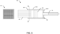
- the housing 302 of the distributor 102 can be a hollow cylindrical member comprising a first circular base 302-1, a second circular base 302-2 parallel to the first circular base 302-1, and a curved lateral surface 302-3 connecting perimeters of the first circular base 302-1, and the second circular base 302-2.
- a bundled group of the tubes 106 can be fluidically disposed within the housing 302, from one of the sides selected from the first circular base 302-1, the second circular 302-2, or the curved lateral surface 302-3.
- the feeder tube 110 can be axially or radially fluidically connected to any of the first circular base 302-1, the second circular 302-2, or the curved lateral surface 302-3 of the distributor 102 such that the distributor 102 can radially or axially supply the fluid received from the feeder tube 110 into the ports associated with the bundled microchannel tubes 106.
- a bundled group of the tubes 106 can be fluidically disposed within the housing 302 through the first circular base 302-1, and the feeder tube 110 can be axially connected to an inlet at the second circular base 302-2 such that the fluid can axially flow from the feeder tube 110 to the ports associated with the bundled microchannel tubes 106.
- the distributor 102 can include a flow disrupter 304 configured coaxially within the housing 302 of the distributor 102.
- the housing 402 402 of the distributor 102 can be a hollow cylindrical member comprising a first circular base 402-1, a second circular base 402-2 parallel to the first base 402-1, and a curved lateral surface 402-3 connecting perimeters of the first base 402-1, and the second base 402-2.
- a bundled group of the tubes 106 can be fluidically disposed within the housing 402 of the distributor 102 through one of the sides of the curved lateral surface 402-3, and the feeder tube 110 can be axially connected to the second circular base 402-2 such that the fluid can be uniformly mixed and evenly distributed into the ports associated with the bundled microchannel tubes 106.
- the distributor 102 can also include the flow disrupter 404 configured coaxially within the housing 402 of the distributor 102.
- the housing 402 402 of the distributor 102 can be a hollow member having a polyhedral shape comprising a first base, a second base parallel to the first base, and a plurality of planar lateral sides connecting perimeters of the first base, and the second base.
- the housing 402 can have a cuboidal shape having four planar sides extending between perimeters of two rectangular bases.
- the housing 402 can have a prism shape having three planar sides extending between perimeters of two triangular bases.
- a bundled group of the tubes 106 can be fluidically disposed within the housing 402, from one of the planar lateral sides of the housing 402 of FIGs 4C and 4D .
- the feeder tube 110 can be fluidically connected to any of the first base, the second base, or any of the planar lateral sides of the distributor 102.
- the housing 402 of the distributor 102 can be a hollow member having a predefined shape defined by a combination of one or more planar sides and one or more curved surfaces. Further, a bundled group of tubes can be fluidically disposed within the housing 402 from one of the sides selected from the planar sides or the curved sides of the housing 402. Furthermore, the feeder tube 110 can be fluidically connected to any of the planar sides or any of the curved sides of the distributor 102. In one or more embodiments, the distributor 102 of FIGs. 4B to 4F can also include the flow disruptor 406 configured coaxially to the planar side or the curved side within the housing 402.
- the housing 502 of the distributor 102 can have a cylindrical shape comprising a first circular base 502-1, a second circular base 502-2 parallel to the first circular base 502-1, and a curved lateral surface 502-3 connecting perimeters of the first circular base 502-1 and the second circular base 502-2.
- multiple bundled groups of the tubes 106 can be fluidically disposed within the housing 502 through multiple sides of the curved lateral surface of the cylinder 502 and the feeder tube 110 can be axially connected to the second circular base 502-2 of the cylinder 502 such that the fluid can be uniformly mixed and evenly distributed into the ports associated with the bundled microchannel tubes 106. As shown in FIG.
- two bundled groups of tubes 106 can be fluidically disposed within the housing 502 through two opposite sides of the curved lateral surface 502-3 of the cylindrical housing 502. Further, as shown in FIG. 5B , four bundled groups of the tubes 106 can be fluidically disposed within the housing 502, from four directions, through the curved lateral surface 502-3 of the cylindrical housing 502. Furthermore, the feeder tube 110 can be axially connected at the second circular base 502-2 of the housing 502 of FIGs. 5A and 5B . In one or more embodiments, the distributor 102 can also include the flow disrupter 504 configured coaxially within the housing 502 of the distributor 102.
- the housing 502 of the distributor 102 can have a polyhedral shape comprising a first base, a second base parallel to the first base, and a plurality of planar lateral sides connecting perimeters of the first base and the second base. Further, multiple bundled groups of the tubes 106 can be fluidically disposed within the housing 502 through multiple sides of the planar lateral surface of the housing 502 and the feeder tube 110 can be axially connected at the second base of the housing 502 such that the fluid can be uniformly mixed and evenly distributed into the ports associated with the bundled microchannel tubes 106. As shown in FIG.
- the housing 502 can have a cuboidal shape having four planar lateral sides connecting perimeters of two rectangular bases, and four bundled groups of the tubes 106 can be fluidically disposed within the housing 502 through four lateral sides of the housing 502.
- the housing 502 can have an octagonal shape having eight planar lateral sides extending between perimeters of two rectangular bases, and eight bundled groups of the tubes 106 can be fluidically disposed within the housing 502 through the eight lateral sides of the housing 502.
- the distributor 102 can also include the flow disrupter 504 configured coaxially within the housing 502 of the distributor 102.
- the feeder tube 110 can be radially connected to the housing 602 of the distributor 102 such that the feeder tube 110 remains off-centered from a central axis of the housing 602. Accordingly, the off-centered feeder tube 110 can allow the fluid to flow in a swirl motion within the housing 602 to evenly mix the fluid and further evenly distribute the mixed fluid into the ports associated with the bundled groups of the tubes.
- the housing 602 of the distributor 102 can have a cylindrical shape comprising a first circular base 602-1, a second circular base 602-2 parallel to the first circular base 602-1, and a curved lateral surface 602-3 connecting perimeters of the first circular base 602-1 and the second circular base 602-2.
- multiple bundled groups of the tubes 106 can be fluidically disposed within the housing 602 through one or more sides of the curved lateral surface 602-3 of the cylindrical housing 602 and/or through the first circular base 602-1.
- the feeder tube 110 can be radially connected to the curved lateral surface 602-3 of the cylindrical housing 602 such that the fluid can flow in a swirl motion within the housing 602 to evenly mix the fluid and further evenly distribute the mixed fluid into the ports associated with the bundled group(s) of the tubes 106.
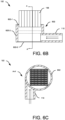
- two bundled groups of tubes 106 can be fluidically disposed within the housing 602 through two opposite sides of the curved lateral surface 602-3 of the cylindrical housing 602. Further, as shown in FIG. 6D , four bundled groups of tubes 106 can be fluidically disposed within the housing 602, from four directions, through the curved lateral surface 602-3 of the cylindrical housing 602. Furthermore, as shown in FIGs. 6B and 6C , a single bundled group of tubes 106 can be fluidically disposed within the housing 602 through the first circular base 602-1 of the cylindrical housing 602.
- the feeder tube 110 can be radially connected to the curved lateral surface 602-3 of the cylindrical housing 602 of FIGs. 6A to 6D .
- the distributor 102 can also include the flow disrupter 604 configured coaxially within the housing 602 of the distributor 102.
- the housing 602 of the distributor 102 can have a polyhedral shape comprising a first base, a second base parallel to the first base, and a plurality of planar lateral sides connecting perimeters of the first base and the second base.
- one or more bundled groups of tubes 106 can be fluidically disposed within the housing 602 through one or more sides of the planar lateral surface of the housing 602 and the feeder tube 110 can be radially connected to one of the lateral sides of the housing 602.
- the housing 602 can have an octagonal shape having eight planar lateral sides extending between perimeters of two rectangular bases, and eight bundled groups of the tubes 106 can be fluidically disposed within the housing 602 through the eight lateral sides of the housing 602. Further, the feeder tube 110 can be radially connected to one of the lateral sides of the housing 602.
- the flow disruptor (304 to 604) of FIGs. 3 to 6E can include a frame comprising a mesh screen with a plurality of holes, however, the flow disruptor (304 to 604) is not limited to the like and can include any other flow disruptor means known in the art, and all such embodiments are well within the scope of the invention.
- this invention (fluid distributor) overcomes the drawbacks, limitations, and shortcomings associated with conventional MCHX having large-volume headers, by providing an improved, efficient, and low-volume refrigerant distributor for microchannel heat exchangers, which can replace the conventional large-volume headers while effectively distributing refrigerant flow into each of the microchannel tubes.
Landscapes
- Engineering & Computer Science (AREA)
- Physics & Mathematics (AREA)
- Mechanical Engineering (AREA)
- Thermal Sciences (AREA)
- General Engineering & Computer Science (AREA)
- Geometry (AREA)
- Heat-Exchange Devices With Radiators And Conduit Assemblies (AREA)
- Devices For Dispensing Beverages (AREA)
Abstract
Description
- This invention relates to the field of heat exchangers, and more particularly, a heat exchanger, and a low-volume fluid distributor for heat exchangers.
- According to a first aspect of the invention there is provided a heat exchanger. The heat exchanger comprises a distributor that comprises a housing of a predefined shape. The heat exchanger further comprises a plurality of microchannel tubes, wherein an inlet end of the plurality of microchannel tubes is bundled in one or more groups, and wherein the inlet end of the one or more bundled groups is fluidically disposed within the housing of the distributor through one or more sides and/or one or more surfaces of the housing of the distributor.
- Optionally, the housing of the distributor is a hollow cylindrical member comprising a first circular base, a second circular base parallel to the first circular base, and a curved lateral surface connecting perimeters of the first circular base and the second circular base, wherein the one or more bundled groups are fluidically disposed within the housing, from one or more directions, through one or more of the first base, the second base, and/or the curved lateral surface, and wherein the heat exchanger further comprises a feeder tube fluidically connected to any of the first circular base, the second circular base, or the curved lateral surface.
- Optionally, the housing of the distributor is a hollow member having a polyhedral shape and comprising a first base, a second base parallel to the first base, and a plurality of planar lateral sides connecting perimeters of the first base and the second base, wherein the one or more bundled groups are fluidically disposed within the housing, from one or more directions, through one or more of the first base, the second base, and/or the planar lateral sides, and wherein the heat exchanger further comprises a feeder tube fluidically connected to any of the first base, the second base, or any of the planar lateral sides.
- Optionally, the housing of the distributor has a conical profile comprising a circular base, and a curved lateral surface extending from a vortex end to the circular base, wherein the distributor comprises an inlet at the vortex end, and a plurality of outlets configured circumferentially around the circular base and in fluidic communication with the inlet via a plurality of fluidic passages extending within the housing.
- Optionally, the inlet end of the microchannel tubes associated with each of the bundled groups are profiled in a curved shape, wherein the curved microchannel tubes are disposed within the circular base of the housing through the plurality of outlets, and wherein the heat exchanger further comprises a feeder tube fluidically connected to the inlet of the housing.
- Optionally, the feeder tube is configured off-centered from a central longitudinal axis of the housing.
- Optionally, the heat exchanger comprises a flow disrupter configured within the housing of the distributor.
- Optionally, the heat exchanger further comprises a collector, wherein an outlet end of the plurality of microchannel tubes is bundled in one or more groups, wherein the one or more bundled groups of the outlet end of the microchannel tubes are fluidically disposed within the collector through one or more sides and/or one or more surfaces of the collector.
- Optionally, a length, between the inlet end and the outlet end, of the plurality of microchannel tubes is configured in a predefined configuration having a predefined number of turns or a predefined number of passes.
- According to a second aspect of the invention there is provided a heat exchanger. The heat exchanger comprises one or more distributors, each comprising a housing of a predefined shape, and a plurality of microchannel tubes, wherein an inlet end of the plurality of microchannel tubes is bundled in one or more first groups, wherein the inlet end of at least one of the bundled first groups is fluidically disposed within the housing associated with one of the distributors through one or more sides and/or one or more surfaces of the corresponding housing.
- Optionally, the heat exchanger further comprises one or more collectors, wherein an outlet end of the plurality of microchannel tubes is bundled in one or more second groups, wherein the outlet end of at least one of the bundled second groups is fluidically disposed within one of the collectors through one or more sides or one or more surfaces of the corresponding collector.
- Optionally, a length, between the inlet end and the outlet end, of the plurality of microchannel tubes is configured in a predefined configuration having a predefined number of turns or a predefined number of passes.
- According to a third aspect of the invention there is provided a fluid distributor for a heat exchanger. The distributor comprises a housing comprising one or more sides and/or one or more surfaces defining a predefined shape and a predefined internal volume, wherein a first end of a plurality of microchannel tubes associated with the heat exchanger are bundled in one or more groups, and wherein the distributor is configured to fluidically accommodate the first end of the one or more bundled groups through the one or more sides and/or the one or more surfaces of the housing.
- Optionally, the housing is a hollow cylindrical member that comprises a first circular base, a second circular base parallel to the first circular base, and a curved lateral surface connecting perimeters of the first circular base, and the second circular base, wherein the one or more bundled groups are fluidically disposed within the housing, from one or more directions, through one or more of the first circular base, the second circular, and/or the curved lateral surface, and wherein any of the first circular base, the second circular base, or the curved lateral surface of the distributor is configured to fluidically accommodate a feeder tube associated with the heat exchanger.
- Optionally, the housing is a hollow member having a polyhedral shape that comprises a first base, a second base parallel to the first base, and a plurality of planar lateral sides connecting perimeters of the first base, and the second base, wherein the one or more bundled groups are fluidically disposed within the housing, from one or more directions, through one or more of the first base, the second base, and/or the planar lateral sides, and wherein any of the first base, the second base, or any of the planar lateral sides of the distributor is configured to fluidically accommodate a feeder tube associated with the heat exchanger.
- Optionally, the housing is a hollow member of the predefined shape being defined by a combination of one or more planar sides and one or more curved surfaces, wherein the one or more bundled groups are fluidically disposed within the housing, from one or more directions, through one or more of the planar sides, and the curved sides, and wherein any of the planar sides, or any of the curved sides of the distributor is configured to fluidically accommodate a feeder tube associated with the heat exchanger.
- Optionally, the housing has a solid conical profile that comprises a circular base, and a curved lateral surface extending from a vortex end to a circular base, wherein the distributor comprises an inlet at the vortex end, and a plurality of outlets configured circumferentially around the circular base and in fluidic communication with the inlet via a plurality of fluidic passages.
- Optionally, the first end of the microchannel tubes associated with each of the bundled groups are profiled in a curved shape, wherein the curved microchannel tubes are disposed within the circular base of the housing through the plurality of outlets, and wherein the inlet of the housing is configured to fluidically accommodate a feeder tube associated with the heat exchanger.
- Optionally, the feeder tube is configured off-centered from a central longitudinal axis of the housing.
- Optionally, the heat exchanger comprises a flow disrupter configured within the housing of the distributor.
- The foregoing summary is illustrative only and is not intended to be in any way limiting. In addition to the illustrative aspects, embodiments, and features described above, further aspects, embodiments, features, and techniques of the invention will become more apparent from the following description taken in conjunction with the drawings.
- The accompanying drawings are included to provide a further understanding of the invention and are incorporated in and constitute a part of this specification. The drawings illustrate exemplary embodiments of the invention and, together with the description, serve to explain the principles of the invention.
- In the drawings, similar components and/or features may have the same reference label. Further, various components of the same type may be distinguished by following the reference label with a second label that distinguishes among the similar components. If only the first reference label is used in the specification, the description is applicable to any one of the similar components having the same first reference label irrespective of the second reference label. Certain exemplary embodiments will now be described in greater detail by way of example only and with reference to the accompanying drawings in which:
-
FIGs. 1A and 1B illustrate exemplary views of the heat exchanger having a single refrigerant circuit comprising a plurality of tubes extending between a low-volume distributor and a low-volume collector in different configurations. -
FIG. 1C illustrates an exemplary view of a heat exchanger comprising multiple low-volume distributors and low-volume collectors. -
FIG. 2A illustrates an exemplary cross-sectional side view of a first embodiment of the distributor having a conical profile. Further,FIG. 2B illustrates an exemplary view depicting the curved profile of the microchannel tubes for fitment into the outlet ports of the distributor ofFIG. 2A . -
FIG. 3 illustrates an exemplary cross-sectional side view of a second embodiment of the distributor having a cylindrical profile, where the feeder tube is axially configured with the housing and the bundled group of tubes. -
FIG. 4A illustrates an exemplary cross-sectional side view of a third embodiment of the distributor, where the bundled group of tubes is configured on one of the lateral sides or surfaces of the distributor, and the feeder tube is axially connected to a base of the distributor. -
FIGs. 4B to 4F illustrate exemplary top view depicting various embodiments of the distributor ofFIG. 4A having different shapes of housing. -
FIG. 5A illustrates an exemplary cross-sectional side view of a fourth embodiment of the distributor, where the bundled groups of tubes are configured on two lateral sides or surfaces of the distributor, and the feeder tube is axially connected to the base of the di stributor. -
FIGs. 5B to 5D illustrate exemplary top view depicting various embodiments of the distributor, where the bundled groups of tubes are configured on different lateral sides or surfaces of the distributor, and the feeder tube is axially connected to the base of the distributor. -
FIG. 6A illustrates an exemplary cross-sectional side view of a fourth embodiment of the distributor, where the bundled groups of tubes are configured on two lateral sides or surfaces of the distributor, and the feeder tube is radially connected to one of the lateral side or surfaces of the distributor. -
FIGs. 6B and 6C illustrate an exemplary cross-sectional side view and top view respectively of a fifth embodiment of the distributor, where a bundled group of tubes is configured on a first base of the distributor, and the feeder tube is radially connected to one of the lateral side or surfaces of the distributor. -
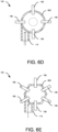
FIGs. 6D and 6E illustrate exemplary views depicting various embodiments of the distributor, where the bundled groups of tubes are configured on different lateral sides or surfaces of the distributor from different directions, and the feeder tube is radially connected to the lateral side or surface of the distributor. - The following is a detailed description of embodiments of the invention depicted in the accompanying drawings. The embodiments are in such detail as to clearly communicate the invention. However, the amount of detail offered is not intended to limit the anticipated variations of embodiments; on the contrary, the intention is to cover all modifications, equivalents, and alternatives falling within the scope of the invention as defined by the appended claims.
- Various terms are used herein. To the extent a term used in a claim is not defined below, it should be given the broadest definition persons in the pertinent art have given that term as reflected in printed publications and issued patents at the time of filing.
- In the specification, reference may be made to the spatial relationships between various components and to the spatial orientation of various aspects of components as the devices are depicted in the attached drawings. However, as will be recognized by those skilled in the art after a complete reading of the specification, the components of this invention. described herein may be positioned in any desired orientation. Thus, the use of terms such as "above," "below," "upper," "lower," "first", "second" or other like terms to describe a spatial relationship between various components or to describe the spatial orientation of aspects of such components should be understood to describe a relative relationship between the components or a spatial orientation of aspects of such components, respectively, as the distributor, collector, MCHX tubes, feeder tube, heat exchanger, and corresponding components, described herein may be oriented in any desired direction.
- Microchannel heat exchangers (MCHX) employing microchannel tubes are crucial components in heat pump systems, facilitating efficient heat transfer between different fluid streams. These heat exchangers are employed in a wide range of applications, including residential and commercial heating, ventilation, and air conditioning (HVAC) systems. Conventional MCHX has relatively large volume headers on both sides of the microchannel tubes or heat exchange section in order to distribute the flow into the tubes and collect the flow leaving the tubes. These headers can be horizontal or vertical header in the form of a cylindrical tube extending along an entire length of the heat exchange section of the MCHX, with individual MCHX tubes spaced by some distance and disposed along a length of the header. These larger volume headers can contribute to increased refrigerant volume requirements, which can result in elevated costs and safety concerns when handling flammable refrigerants. Furthermore, the high number of connections on conventional headers escalates the risk of potential failure points, impacting reliability and maintenance efforts.
- There is, therefore, a need for a solution to address the challenges posed by conventional MCHX having large-volume headers, by providing an improved, efficient, and low-volume refrigerant distributor for microchannel heat exchangers, which can replace the conventional large-volume headers while effectively distributing refrigerant flow into each of the microchannel tubes.
- Referring to
FIGs. 1A to 1B , theheat exchanger 100 can include adistributor 102, acollector 104, and a plurality ofmicrochannel tubes 106 extending between thedistributor 102 and thecollector 104. The inlet end of themicrochannel tubes 106 can be bundled in one or more groups (first groups) that can be fluidically disposed within (embedded) thedistributor 102 through one or more sides and/or one or more surfaces of thedistributor 102. Theheat exchanger 100 can further include afeeder tube 110 fluidically connected to an inlet side of thedistributor 102 to supply the fluid into the bundledmicrochannel tubes 106 through thedistributor 102. The detailed construction of thedistributor 102 has been described later in conjunction withFIGs. 2A to 6D . - Further, in one or more embodiments, the outlet end of the
microchannel tubes 106 can also be bundled in one or more groups (second groups) that can be fluidically disposed within thecollector 104 through one or more sides and/or one or more surfaces of thecollector 104. However, the outlet end of themicrochannel tubes 106 can also be directly fluidically disposed within thecollector 104. - In one or more embodiments, a length, between the inlet end and the outlet end, of the
microchannel tubes 106 may form a heat exchange section that can be configured in a predefined configuration having a predefined number of turns, a predefined number of passes, or both. Themicrochannel tubes 106 or heat exchange section can facilitate heat exchange between a fluid (refrigerant) flowing through thetubes 106 and another fluid (air) flowing across the heat exchange section. Further, theheat exchanger 100 or heat exchange section can include a plurality of heat-dissipating fins configured between themicrochannel tubes 106 to increase the exchange/transfer area of thetubes 106 and correspondingly enhance the heat exchange. - In one or more embodiments, the
tubes 106 can be configured in a serpentine configuration having a predefined number of passes and turns in each of the separated circuits as shown inFIG. 1A , the integrated circuits as shown inFIG. 1B or combinations thereof. Referring toFIG. 1A . in the separated circuits, the length, between the inlet end and the outlet end, of each of theindividual microchannel tubes 106 can have a predefined number of passes and turns, which extend separately fromother microchannel tubes 106. Each of the separated circuits may have the same or different length. Each of the separated circuits may have the same or different number of passes or turns. Further, referring toFIG. 1B . in integrated circuits, the length, between the inlet end and the outlet end, of themicrochannel tubes 106 can extend substantially parallel with each other while having a predefined number of passes and turns. - Referring to
FIG. 1C , in one or more embodiments, theheat exchanger 100 can include one or more distributors 102-1 to 102-3, one or more collectors 104-1 to 104-3, and the plurality of microchannel tubes 106-A to 106-C fluidically connected and extending between the distributors 102-1 to 102-3, and the collectors 104-1 to 104-3. The inlet end of the microchannel tubes 106-A to 106-C can be bundled in one or more first groups and the outlet inlet end of the microchannel tubes 106-A to 106-C can be further bundled in one or more second groups. The inlet end of at least one of the bundled first groups can be fluidically disposed within one of the distributors 102-1 to 102-3 through one or more sides and/or one or more surfaces of the corresponding housing of the distributors 102-1 to 102-3. - Further, the outlet end of at least one of the bundled second groups of the tubes 106-A to 106-C can be fluidically disposed within one of the collectors 104-1 to 104-3 through one or more sides or one or more surfaces of the corresponding collector. However, in one or more embodiments, the outlet end of the microchannel tubes 106-A to 106-C may not be bundled in groups and can be directly fluidically disposed within one of the collectors through one or more sides or one or more surfaces of the
corresponding collector 104. Furthermore (not shown), in one or more embodiments, theheat exchanger 100 can include asingle collector 104, where the outlet end of themicrochannel tubes 106 may not be bundled in groups and can be directly fluidically disposed within thecollector 104 through one or more sides or one or more surfaces of thecorresponding collector 104. - In one or more embodiments, an inlet side of each of the distributors 102-1 to 102-3 can be fluidically connected to a
common distributor 108. Further, thecommon distributor 108 can be fluidically connected to afeeder tube 110 associated with theheat exchanger 100. Thecommon distributor 108 can supply an equal volume of fluid (received from the feeder tube 110) to each of the distributors 102-1 to 102-3. In addition, an outlet side of each of the collectors 104-1 to 104-3 can be further fluidically connected to a common collector line to receive the fluid from each of the collectors 104-1 to 104-3. - In one or more embodiments, the length, between the inlet end and the outlet end, of the plurality of
microchannel tubes 106 can be configured in a predefined configuration having a predefined number of turns or a predefined number of passes to form the heat exchange section. In addition, theheat exchanger 100 or heat exchange section can include a plurality of heat-dissipating fins configured between themicrochannel tubes 106 to increase the exchange/transfer area of thetubes 106 and correspondingly enhance the heat exchange. - Referring to
FIGs. 2A to 6D , thedistributor 102 can include a housing comprising one or more sides and/or one or more surfaces defining a predefined shape and a predefined internal volume. Thedistributor 102 can be configured to fluidically accommodate the first end (inlet end) of the bundled groups of themicrochannel tubes 106 through one or more sides and/or one or more surfaces of the housing. In one or more embodiments, thedistributor 102 can be further configured to fluidically accommodate thefeeder tube 110 associated with the heat exchanger, either radially or axially, from any of the sides or surfaces of the housing of thedistributor 102. - In one or more embodiments, the first end of the
microchannel tubes 106 can be stacked or bundled vertically, horizontally, or in other configurations. Further, a portion of a wall associated with the corresponding sides and/or surfaces of the housing can be removed and the first end of the bundledgroup 106 can be embedded within the housing through the removed portion and thefeeder tube 110 can be connected to an inlet of the housing. Further, the embedded bundledgroups 106 can be brazed along with the housing to fluidically seal thedistributor 102 such that the fluid can flow from thefeeder tube 110 into the bundled groups of themicrochannel tubes 106 via the housing without any leakage. - Referring to
FIG. 2A , in one or more embodiments, the housing 202 of thedistributor 102 can have a solid conical profile comprising a circular base 202-1, and a curved lateral surface 202-3 extending from a vortex end 202-2 to the circular base 202-1. Thedistributor 102 can include aninlet 204 at the vortex end 202-2 and a plurality ofoutlets 206 configured circumferentially around the circular base 202-1 and in fluidic communication with theinlet 204 via a plurality of fluidic passages. Further, as shown inFIG. 2B , the first end of themicrochannel tubes 106 associated with each of the bundled groups can be profiled in a curved shape based on the profile of the circular base 202-1 of thedistributor 102. Accordingly, thecurved microchannel tubes 106 can be disposed within the circular base 202-1 of the housing 202 through the plurality ofoutlets 206. Further, thefeeder tube 110 can be fluidically connected to theinlet 204 of the housing 202 such that thedistributor 102 can radially supply the fluid received from thefeeder tube 110 into the ports associated with the bundledmicrochannel tubes 106. - In one or more embodiments, referring to
FIG. 3 , thehousing 302 of thedistributor 102 can be a hollow cylindrical member comprising a first circular base 302-1, a second circular base 302-2 parallel to the first circular base 302-1, and a curved lateral surface 302-3 connecting perimeters of the first circular base 302-1, and the second circular base 302-2. Further, a bundled group of thetubes 106 can be fluidically disposed within thehousing 302, from one of the sides selected from the first circular base 302-1, the second circular 302-2, or the curved lateral surface 302-3. Furthermore, thefeeder tube 110 can be axially or radially fluidically connected to any of the first circular base 302-1, the second circular 302-2, or the curved lateral surface 302-3 of thedistributor 102 such that thedistributor 102 can radially or axially supply the fluid received from thefeeder tube 110 into the ports associated with the bundledmicrochannel tubes 106. - Referring to
FIG. 3 , in one or more embodiments, a bundled group of thetubes 106 can be fluidically disposed within thehousing 302 through the first circular base 302-1, and thefeeder tube 110 can be axially connected to an inlet at the second circular base 302-2 such that the fluid can axially flow from thefeeder tube 110 to the ports associated with the bundledmicrochannel tubes 106. In one or more embodiments, thedistributor 102 can include aflow disrupter 304 configured coaxially within thehousing 302 of thedistributor 102. - Referring to
FIGs. 4A and 4B , in one or more embodiments, thehousing 402 402 of thedistributor 102 can be a hollow cylindrical member comprising a first circular base 402-1, a second circular base 402-2 parallel to the first base 402-1, and a curved lateral surface 402-3 connecting perimeters of the first base 402-1, and the second base 402-2. Further, a bundled group of thetubes 106 can be fluidically disposed within thehousing 402 of thedistributor 102 through one of the sides of the curved lateral surface 402-3, and thefeeder tube 110 can be axially connected to the second circular base 402-2 such that the fluid can be uniformly mixed and evenly distributed into the ports associated with the bundledmicrochannel tubes 106. In one or more embodiments, thedistributor 102 can also include theflow disrupter 404 configured coaxially within thehousing 402 of thedistributor 102. - In one or more embodiments, referring to
FIGs. 4C and 4D , thehousing 402 402 of thedistributor 102 can be a hollow member having a polyhedral shape comprising a first base, a second base parallel to the first base, and a plurality of planar lateral sides connecting perimeters of the first base, and the second base. As shown inFIG. 4C , thehousing 402 can have a cuboidal shape having four planar sides extending between perimeters of two rectangular bases. Further, as shown inFIG. 4D , thehousing 402 can have a prism shape having three planar sides extending between perimeters of two triangular bases. Further, a bundled group of thetubes 106 can be fluidically disposed within thehousing 402, from one of the planar lateral sides of thehousing 402 ofFIGs 4C and 4D . Furthermore, thefeeder tube 110 can be fluidically connected to any of the first base, the second base, or any of the planar lateral sides of thedistributor 102. - In one or more embodiments, referring to
FIGs. 4E and 4F , thehousing 402 of thedistributor 102 can be a hollow member having a predefined shape defined by a combination of one or more planar sides and one or more curved surfaces. Further, a bundled group of tubes can be fluidically disposed within thehousing 402 from one of the sides selected from the planar sides or the curved sides of thehousing 402. Furthermore, thefeeder tube 110 can be fluidically connected to any of the planar sides or any of the curved sides of thedistributor 102. In one or more embodiments, thedistributor 102 ofFIGs. 4B to 4F can also include the flow disruptor 406 configured coaxially to the planar side or the curved side within thehousing 402. - Referring to
FIGs. 5A and5B , in one or more embodiments, thehousing 502 of thedistributor 102 can have a cylindrical shape comprising a first circular base 502-1, a second circular base 502-2 parallel to the first circular base 502-1, and a curved lateral surface 502-3 connecting perimeters of the first circular base 502-1 and the second circular base 502-2. Further, multiple bundled groups of thetubes 106 can be fluidically disposed within thehousing 502 through multiple sides of the curved lateral surface of thecylinder 502 and thefeeder tube 110 can be axially connected to the second circular base 502-2 of thecylinder 502 such that the fluid can be uniformly mixed and evenly distributed into the ports associated with the bundledmicrochannel tubes 106. As shown inFIG. 5A , two bundled groups oftubes 106 can be fluidically disposed within thehousing 502 through two opposite sides of the curved lateral surface 502-3 of thecylindrical housing 502. Further, as shown inFIG. 5B , four bundled groups of thetubes 106 can be fluidically disposed within thehousing 502, from four directions, through the curved lateral surface 502-3 of thecylindrical housing 502. Furthermore, thefeeder tube 110 can be axially connected at the second circular base 502-2 of thehousing 502 ofFIGs. 5A and5B . In one or more embodiments, thedistributor 102 can also include theflow disrupter 504 configured coaxially within thehousing 502 of thedistributor 102. - Referring to
FIGs. 5C and 5D , in one or more embodiments, thehousing 502 of thedistributor 102 can have a polyhedral shape comprising a first base, a second base parallel to the first base, and a plurality of planar lateral sides connecting perimeters of the first base and the second base. Further, multiple bundled groups of thetubes 106 can be fluidically disposed within thehousing 502 through multiple sides of the planar lateral surface of thehousing 502 and thefeeder tube 110 can be axially connected at the second base of thehousing 502 such that the fluid can be uniformly mixed and evenly distributed into the ports associated with the bundledmicrochannel tubes 106. As shown inFIG. 5C , thehousing 502 can have a cuboidal shape having four planar lateral sides connecting perimeters of two rectangular bases, and four bundled groups of thetubes 106 can be fluidically disposed within thehousing 502 through four lateral sides of thehousing 502. Further, as shown inFIG. 5D , thehousing 502 can have an octagonal shape having eight planar lateral sides extending between perimeters of two rectangular bases, and eight bundled groups of thetubes 106 can be fluidically disposed within thehousing 502 through the eight lateral sides of thehousing 502. In one or more embodiments, thedistributor 102 can also include theflow disrupter 504 configured coaxially within thehousing 502 of thedistributor 102. - Referring to
FIGs. 6A to 6E , in one or more embodiments, thefeeder tube 110 can be radially connected to thehousing 602 of thedistributor 102 such that thefeeder tube 110 remains off-centered from a central axis of thehousing 602. Accordingly, the off-centeredfeeder tube 110 can allow the fluid to flow in a swirl motion within thehousing 602 to evenly mix the fluid and further evenly distribute the mixed fluid into the ports associated with the bundled groups of the tubes. - Referring to
FIGs. 6A to 6D , in one or more embodiments, thehousing 602 of thedistributor 102 can have a cylindrical shape comprising a first circular base 602-1, a second circular base 602-2 parallel to the first circular base 602-1, and a curved lateral surface 602-3 connecting perimeters of the first circular base 602-1 and the second circular base 602-2. Further, multiple bundled groups of thetubes 106 can be fluidically disposed within thehousing 602 through one or more sides of the curved lateral surface 602-3 of thecylindrical housing 602 and/or through the first circular base 602-1. Furthermore, thefeeder tube 110 can be radially connected to the curved lateral surface 602-3 of thecylindrical housing 602 such that the fluid can flow in a swirl motion within thehousing 602 to evenly mix the fluid and further evenly distribute the mixed fluid into the ports associated with the bundled group(s) of thetubes 106. - As shown in
FIG. 6A , two bundled groups oftubes 106 can be fluidically disposed within thehousing 602 through two opposite sides of the curved lateral surface 602-3 of thecylindrical housing 602. Further, as shown inFIG. 6D , four bundled groups oftubes 106 can be fluidically disposed within thehousing 602, from four directions, through the curved lateral surface 602-3 of thecylindrical housing 602. Furthermore, as shown inFIGs. 6B and 6C , a single bundled group oftubes 106 can be fluidically disposed within thehousing 602 through the first circular base 602-1 of thecylindrical housing 602. In addition, thefeeder tube 110 can be radially connected to the curved lateral surface 602-3 of thecylindrical housing 602 ofFIGs. 6A to 6D . In one or more embodiments, thedistributor 102 can also include the flow disrupter 604 configured coaxially within thehousing 602 of thedistributor 102. - Referring to
FIG. 6E , in one or more embodiments, thehousing 602 of thedistributor 102 can have a polyhedral shape comprising a first base, a second base parallel to the first base, and a plurality of planar lateral sides connecting perimeters of the first base and the second base. Further, one or more bundled groups oftubes 106 can be fluidically disposed within thehousing 602 through one or more sides of the planar lateral surface of thehousing 602 and thefeeder tube 110 can be radially connected to one of the lateral sides of thehousing 602. As shown, but not limited to the like, thehousing 602 can have an octagonal shape having eight planar lateral sides extending between perimeters of two rectangular bases, and eight bundled groups of thetubes 106 can be fluidically disposed within thehousing 602 through the eight lateral sides of thehousing 602. Further, thefeeder tube 110 can be radially connected to one of the lateral sides of thehousing 602. - In one or more embodiments, the flow disruptor (304 to 604) of
FIGs. 3 to 6E can include a frame comprising a mesh screen with a plurality of holes, however, the flow disruptor (304 to 604) is not limited to the like and can include any other flow disruptor means known in the art, and all such embodiments are well within the scope of the invention. - It should be obvious to a person skilled in the art that while various embodiments of this invention have been elaborated for the distributor having specific shapes/profiles comprising specific number of sides and surfaces for the sake of simplicity and better explanation purpose, however, the teachings of this specification are equally applicable for the distributor having other shapes/profiles as well, as far as the bundled group(s) of tubes are disposed in the housing of the distributor from any side or surface of the housing, and all such embodiments are well within the scope of this invention.
- Thus, this invention (fluid distributor) overcomes the drawbacks, limitations, and shortcomings associated with conventional MCHX having large-volume headers, by providing an improved, efficient, and low-volume refrigerant distributor for microchannel heat exchangers, which can replace the conventional large-volume headers while effectively distributing refrigerant flow into each of the microchannel tubes.
- While the invention has been described with reference to exemplary embodiments, it will be understood by those skilled in the art that various changes may be made and equivalents may be substituted for elements thereof without departing from the scope of the invention as defined by the appended claims. Modifications may be made to adopt a particular situation or material to the teachings of the invention without departing from the scope thereof. Therefore, it is intended that the invention not be limited to the particular embodiment disclosed, but that the invention includes all embodiments falling within the scope of the invention as defined by the appended claims.
- In interpreting the specification, all terms should be interpreted in the broadest possible manner consistent with the context. In particular, the terms "comprises" and "comprising" should be interpreted as referring to elements, components, or steps in a non-exclusive manner, indicating that the referenced elements, components, or steps may be present, or utilized, or combined with other elements, components, or steps that are not expressly referenced. Where the specification claims refer to at least one of something selected from the group consisting of A, B, C ....and N, the text should be interpreted as requiring only one element from the group, not A plus N, or B plus N, etc.
- The following numbered clauses set out embodiments of the invention which may or may not presently be claimed, but which may form the basis for future amendment or a divisional application.
- 1. A heat exchanger comprising:
- one or more distributors, each comprising a housing of a predefined shape, and
- a plurality of microchannel tubes, wherein an inlet end of the plurality of microchannel tubes is bundled in one or more first groups,
- wherein the inlet end of at least one of the bundled first groups is fluidically disposed within the housing associated with one of the distributors through one or more sides and/or one or more surfaces of the corresponding housing.
- 2. The heat exchanger of clause 1, further comprising one or more collectors, wherein an outlet end of the plurality of microchannel tubes is bundled in one or more second groups, wherein the outlet end of at least one of the bundled second groups is fluidically disposed within one of the collectors through one or more sides or one or more surfaces of the corresponding collector.
- 3. The heat exchanger of clause 2, wherein a length, between the inlet end and the outlet end, of the plurality of microchannel tubes is configured in a predefined configuration having a predefined number of turns or a predefined number of passes.
Claims (15)
- A heat exchanger (100) comprising:a distributor (102) that comprises a housing (202; 302; 402; 502; 602) of a predefined shape, anda plurality of microchannel tubes (106), wherein an inlet end of the plurality of microchannel tubes is bundled in one or more groups, andwherein the inlet end of the one or more bundled groups is fluidically disposed within the housing of the distributor through one or more sides and/or one or more surfaces of the housing of the distributor.
- The heat exchanger (100) of claim 1, wherein the housing (302; 402; 502; 602) of the distributor (102) is a hollow cylindrical member comprising a first circular base (302-1; 402-1; 502-1; 602-1), a second circular base (302-2; 402-2; 502-2; 602-2) parallel to the first circular base, and a curved lateral surface (302-3; 402-3; 502-3; 602-3) connecting perimeters of the first circular base and the second circular base, wherein the one or more bundled groups are fluidically disposed within the housing, from one or more directions, through one or more of the first base, the second base, and/or the curved lateral surface, and
wherein the heat exchanger further comprises a feeder tube (110) fluidically connected to any of the first circular base, the second circular base, or the curved lateral surface. - The heat exchanger (100) of claim 1, wherein the housing (402; 502; 602) of the distributor (102) is a hollow member having a polyhedral shape and comprising a first base, a second base parallel to the first base, and a plurality of planar lateral sides connecting perimeters of the first base and the second base, wherein the one or more bundled groups are fluidically disposed within the housing, from one or more directions, through one or more of the first base, the second base, and/or the planar lateral sides, and
wherein the heat exchanger further comprises a feeder tube (110) fluidically connected to any of the first base, the second base, or any of the planar lateral sides. - The heat exchanger (100) of claim 1, wherein the housing (202) of the distributor (102) has a conical profile comprising a circular base (202-1), and a curved lateral surface (202-3) extending from a vortex end (202-2) to the circular base, wherein the distributor comprises an inlet (204) at the vortex end, and a plurality of outlets (206) configured circumferentially around the circular base and in fluidic communication with the inlet via a plurality of fluidic passages extending within the housing.
- The heat exchanger (100) of claim 4, wherein the inlet end of the microchannel tubes (106) associated with each of the bundled groups are profiled in a curved shape, and wherein the curved microchannel tubes are disposed within the circular base (202-1) of the housing (202) through the plurality of outlets (206), and
wherein the heat exchanger further comprises a feeder tube (110) fluidically connected to the inlet (204) of the housing. - The heat exchanger (100) of claim 2, 3 or 5, wherein the feeder tube (110) is configured off-centered from a central longitudinal axis of the housing (202; 302; 402; 502; 602).
- The heat exchanger (100) of any of claims 1 to 6, wherein the heat exchanger comprises a flow disrupter (304; 404; 504; 604) configured within the housing (202; 302; 402; 502; 602) of the distributor (102).
- The heat exchanger (100) of any of claims 1 to 7, further comprising a collector (104), wherein an outlet end of the plurality of microchannel tubes (106) is bundled in one or more groups, wherein the one or more bundled groups of the outlet end of the microchannel tubes are fluidically disposed within the collector through one or more sides and/or one or more surfaces of the collector,
optionally,
wherein a length, between the inlet end and the outlet end, of the plurality of microchannel tubes is configured in a predefined configuration having a predefined number of turns or a predefined number of passes. - A fluid distributor (102) for a heat exchanger (100), the distributor comprising:a housing (202; 302; 402; 502; 602) comprising one or more sides and/or one or more surfaces defining a predefined shape and a predefined internal volume, andwherein a first end of a plurality of microchannel tubes (106) associated with the heat exchanger are bundled in one or more groups, andwherein the distributor is configured to fluidically accommodate the first end of the one or more bundled groups through the one or more sides and/or the one or more surfaces of the housing.
- The fluid distributor (102) of claim 9, wherein the housing (302; 402; 502; 602) is a hollow cylindrical member comprising a first circular base (302-1; 402-1; 502-1; 602-1), a second circular base (302-2; 402-2; 502-2; 602-2) parallel to the first circular base, and a curved lateral surface (302-3; 402-3; 502-3; 602-3) connecting perimeters of the first circular base, and the second circular base, wherein the one or more bundled groups are fluidically disposed within the housing, from one or more directions, through one or more of the first circular base, the second circular, and/or the curved lateral surface, and
wherein any of the first circular base, the second circular base, or the curved lateral surface of the distributor is configured to fluidically accommodate a feeder tube (110) associated with the heat exchanger (100). - The fluid distributor (102) of claim 9, wherein the housing (402; 502; 602) is a hollow member having a polyhedral shape comprising a first base, a second base parallel to the first base, and a plurality of planar lateral sides connecting perimeters of the first base, and the second base, wherein the one or more bundled groups are fluidically disposed within the housing, from one or more directions, through one or more of the first base, the second base, and/or the planar lateral sides, and
wherein any of the first base, the second base, or any of the planar lateral sides of the distributor is configured to fluidically accommodate a feeder tube (110) associated with the heat exchanger (100). - The fluid distributor of claim 9, wherein the housing (402) is a hollow member of the predefined shape being defined by a combination of one or more planar sides and one or more curved surfaces, wherein the one or more bundled groups are fluidically disposed within the housing, from one or more directions, through one or more of the planar sides, and the curved sides, and
wherein any of the planar sides, or any of the curved sides of the distributor is configured to fluidically accommodate a feeder tube (110) associated with the heat exchanger (100). - The fluid distributor (102) of claim 9, wherein the housing (202) has a solid conical profile comprising a circular base (202-1), and a curved lateral surface (202-3) extending from a vortex end (202-2) to a circular base, wherein the distributor comprises an inlet (204) at the vortex end, and a plurality of outlets (206) configured circumferentially around the circular base and in fluidic communication with the inlet via a plurality of fluidic passages, optionally wherein the first end of the microchannel tubes (106) associated with each of the bundled groups are profiled in a curved shape, and wherein the curved microchannel tubes are disposed within the circular base (202-1) of the housing through the plurality of outlets (206), and wherein the inlet (204) of the housing is configured to fluidically accommodate a feeder tube (110) associated with the heat exchanger (100).
- The fluid distributor (102) of claim 10, 11, or 13, wherein the feeder tube (110) is off-centered from a central longitudinal axis of the housing (202; 302; 402; 502; 602).
- The fluid distributor (100) of any of claims 9 to 14, wherein the distributor (102) comprises a flow disrupter (304; 404; 504; 604) configured within the housing (202; 302; 402; 502; 602) of the distributor .
Applications Claiming Priority (1)
| Application Number | Priority Date | Filing Date | Title |
|---|---|---|---|
| US202363591802P | 2023-10-20 | 2023-10-20 |
Publications (1)
| Publication Number | Publication Date |
|---|---|
| EP4542162A1 true EP4542162A1 (en) | 2025-04-23 |
Family
ID=93061473
Family Applications (1)
| Application Number | Title | Priority Date | Filing Date |
|---|---|---|---|
| EP24205547.3A Pending EP4542162A1 (en) | 2023-10-20 | 2024-10-09 | Microchannel heat exchanger and a fluid distributor thereof |
Country Status (3)
| Country | Link |
|---|---|
| US (1) | US20250129998A1 (en) |
| EP (1) | EP4542162A1 (en) |
| CN (1) | CN119860686A (en) |
Citations (8)
| Publication number | Priority date | Publication date | Assignee | Title |
|---|---|---|---|---|
| JPS4710952U (en) * | 1971-02-26 | 1972-10-09 | ||
| DE19729497A1 (en) * | 1997-07-10 | 1999-01-14 | Behr Gmbh & Co | Flat tube heat exchanger for car air-conditioning plant |
| US20110132585A1 (en) * | 2008-03-07 | 2011-06-09 | Carrier Corporation | Heat exchanger tube configuration for improved flow distribution |
| EP2372288A1 (en) * | 2010-03-31 | 2011-10-05 | Valeo Systèmes Thermiques | Heat exchanger for air conditioning device with reduced ends |
| EP3165866A1 (en) * | 2015-11-05 | 2017-05-10 | TT&C Thermotransmission & Cooling UG | Heat exchanger, in particular for high-pressure refrigerant |
| JP2017133814A (en) * | 2016-01-29 | 2017-08-03 | ダイキン工業株式会社 | Heat exchanger |
| US20200300515A1 (en) * | 2017-06-09 | 2020-09-24 | Mitsubishi Electric Corporation | Heat exchanger and refrigeration cycle apparatus |
| WO2023078399A1 (en) * | 2021-11-04 | 2023-05-11 | 浙江盾安人工环境股份有限公司 | Micro-channel heat exchanger |
-
2024
- 2024-10-09 EP EP24205547.3A patent/EP4542162A1/en active Pending
- 2024-10-16 US US18/916,822 patent/US20250129998A1/en active Pending
- 2024-10-18 CN CN202411457988.4A patent/CN119860686A/en active Pending
Patent Citations (8)
| Publication number | Priority date | Publication date | Assignee | Title |
|---|---|---|---|---|
| JPS4710952U (en) * | 1971-02-26 | 1972-10-09 | ||
| DE19729497A1 (en) * | 1997-07-10 | 1999-01-14 | Behr Gmbh & Co | Flat tube heat exchanger for car air-conditioning plant |
| US20110132585A1 (en) * | 2008-03-07 | 2011-06-09 | Carrier Corporation | Heat exchanger tube configuration for improved flow distribution |
| EP2372288A1 (en) * | 2010-03-31 | 2011-10-05 | Valeo Systèmes Thermiques | Heat exchanger for air conditioning device with reduced ends |
| EP3165866A1 (en) * | 2015-11-05 | 2017-05-10 | TT&C Thermotransmission & Cooling UG | Heat exchanger, in particular for high-pressure refrigerant |
| JP2017133814A (en) * | 2016-01-29 | 2017-08-03 | ダイキン工業株式会社 | Heat exchanger |
| US20200300515A1 (en) * | 2017-06-09 | 2020-09-24 | Mitsubishi Electric Corporation | Heat exchanger and refrigeration cycle apparatus |
| WO2023078399A1 (en) * | 2021-11-04 | 2023-05-11 | 浙江盾安人工环境股份有限公司 | Micro-channel heat exchanger |
Also Published As
| Publication number | Publication date |
|---|---|
| CN119860686A (en) | 2025-04-22 |
| US20250129998A1 (en) | 2025-04-24 |
Similar Documents
| Publication | Publication Date | Title |
|---|---|---|
| EP2278246B1 (en) | Distributor tube with improved uniformity of refrigerant fluid distribution | |
| US6220340B1 (en) | Heat exchanger with dimpled bypass channel | |
| EP2082181B1 (en) | Parallel flow heat exchanger | |
| US5634518A (en) | Full fin evaporator core | |
| US20110042049A1 (en) | Parallel flow evaporator with spiral inlet manifold | |
| US20050051318A1 (en) | Heat exchanger | |
| US20250129998A1 (en) | Microchannel Heat Exchanger And A Fluid Distributor Thereof | |
| EP1971815B1 (en) | Spirally wound, layered tube heat exchanger | |
| EP4425082A1 (en) | Micro-channel heat exchanger | |
| CN111912283B (en) | Liquid separating structure and heat exchanger | |
| CN212390898U (en) | Liquid separation structure and heat exchanger | |
| EP4517247A1 (en) | Fluid distributor for microchannel heat exchanger | |
| CN111336832A (en) | Heat exchanger | |
| EP4589238A1 (en) | A fluid distributor for a heat exchanger | |
| US20250137738A1 (en) | Microchannel heat exchanger | |
| CN111520934A (en) | Heat exchanger and air conditioner with same | |
| US20250283673A1 (en) | Laminated header for a microchannel heat exchanger | |
| US12523434B2 (en) | Refrigerant distribution and charge balancing system for heat exchangers | |
| EP4607138A1 (en) | A fluid distributor for an inlet header of a heat exchanger | |
| US20250369708A1 (en) | Fluid distributor for microchannel heat exchanger | |
| EP4700319A1 (en) | Fluid distributor for microchannel heat exchanger | |
| EP4664045A1 (en) | Serpentine heat exchanger | |
| US20250155199A1 (en) | Microchannel Heat Exchanger | |
| EP4400795A1 (en) | Simple distributor for inlet manifold of microchannel heat exchanger | |
| EP1229294B1 (en) | Plate type heat exchanger |
Legal Events
| Date | Code | Title | Description |
|---|---|---|---|
| PUAI | Public reference made under article 153(3) epc to a published international application that has entered the european phase |
Free format text: ORIGINAL CODE: 0009012 |
|
| STAA | Information on the status of an ep patent application or granted ep patent |
Free format text: STATUS: THE APPLICATION HAS BEEN PUBLISHED |
|
| AK | Designated contracting states |
Kind code of ref document: A1 Designated state(s): AL AT BE BG CH CY CZ DE DK EE ES FI FR GB GR HR HU IE IS IT LI LT LU LV MC ME MK MT NL NO PL PT RO RS SE SI SK SM TR |
|
| STAA | Information on the status of an ep patent application or granted ep patent |
Free format text: STATUS: REQUEST FOR EXAMINATION WAS MADE |
|
| 17P | Request for examination filed |
Effective date: 20251021 |
|
| STAA | Information on the status of an ep patent application or granted ep patent |
Free format text: STATUS: EXAMINATION IS IN PROGRESS |
|
| 17Q | First examination report despatched |
Effective date: 20260309 |