EP4542124A1 - Air conditioner - Google Patents
Air conditioner Download PDFInfo
- Publication number
- EP4542124A1 EP4542124A1 EP23839436.5A EP23839436A EP4542124A1 EP 4542124 A1 EP4542124 A1 EP 4542124A1 EP 23839436 A EP23839436 A EP 23839436A EP 4542124 A1 EP4542124 A1 EP 4542124A1
- Authority
- EP
- European Patent Office
- Prior art keywords
- water
- heat exchanger
- supply
- channel
- filter
- Prior art date
- Legal status (The legal status is an assumption and is not a legal conclusion. Google has not performed a legal analysis and makes no representation as to the accuracy of the status listed.)
- Pending
Links
Images











Classifications
-
- F—MECHANICAL ENGINEERING; LIGHTING; HEATING; WEAPONS; BLASTING
- F24—HEATING; RANGES; VENTILATING
- F24F—AIR-CONDITIONING; AIR-HUMIDIFICATION; VENTILATION; USE OF AIR CURRENTS FOR SCREENING
- F24F5/00—Air-conditioning systems or apparatus not covered by F24F1/00 or F24F3/00, e.g. using solar heat or combined with household units such as an oven or water heater
- F24F5/0007—Air-conditioning systems or apparatus not covered by F24F1/00 or F24F3/00, e.g. using solar heat or combined with household units such as an oven or water heater cooling apparatus specially adapted for use in air-conditioning
- F24F5/0035—Air-conditioning systems or apparatus not covered by F24F1/00 or F24F3/00, e.g. using solar heat or combined with household units such as an oven or water heater cooling apparatus specially adapted for use in air-conditioning using evaporation
-
- F—MECHANICAL ENGINEERING; LIGHTING; HEATING; WEAPONS; BLASTING
- F24—HEATING; RANGES; VENTILATING
- F24F—AIR-CONDITIONING; AIR-HUMIDIFICATION; VENTILATION; USE OF AIR CURRENTS FOR SCREENING
- F24F1/00—Room units for air-conditioning, e.g. separate or self-contained units or units receiving primary air from a central station
- F24F1/02—Self-contained room units for air-conditioning, i.e. with all apparatus for treatment installed in a common casing
- F24F1/039—Self-contained room units for air-conditioning, i.e. with all apparatus for treatment installed in a common casing using water to enhance cooling, e.g. spraying onto condensers
-
- F—MECHANICAL ENGINEERING; LIGHTING; HEATING; WEAPONS; BLASTING
- F24—HEATING; RANGES; VENTILATING
- F24F—AIR-CONDITIONING; AIR-HUMIDIFICATION; VENTILATION; USE OF AIR CURRENTS FOR SCREENING
- F24F12/00—Use of energy recovery systems in air conditioning, ventilation or screening
- F24F12/001—Use of energy recovery systems in air conditioning, ventilation or screening with heat-exchange between supplied and exhausted air
- F24F12/006—Use of energy recovery systems in air conditioning, ventilation or screening with heat-exchange between supplied and exhausted air using an air-to-air heat exchanger
-
- F—MECHANICAL ENGINEERING; LIGHTING; HEATING; WEAPONS; BLASTING
- F24—HEATING; RANGES; VENTILATING
- F24F—AIR-CONDITIONING; AIR-HUMIDIFICATION; VENTILATION; USE OF AIR CURRENTS FOR SCREENING
- F24F13/00—Details common to, or for air-conditioning, air-humidification, ventilation or use of air currents for screening
- F24F13/22—Means for preventing condensation or evacuating condensate
- F24F13/222—Means for preventing condensation or evacuating condensate for evacuating condensate
-
- F—MECHANICAL ENGINEERING; LIGHTING; HEATING; WEAPONS; BLASTING
- F24—HEATING; RANGES; VENTILATING
- F24F—AIR-CONDITIONING; AIR-HUMIDIFICATION; VENTILATION; USE OF AIR CURRENTS FOR SCREENING
- F24F8/00—Treatment, e.g. purification, of air supplied to human living or working spaces otherwise than by heating, cooling, humidifying or drying
- F24F8/10—Treatment, e.g. purification, of air supplied to human living or working spaces otherwise than by heating, cooling, humidifying or drying by separation, e.g. by filtering
- F24F8/117—Treatment, e.g. purification, of air supplied to human living or working spaces otherwise than by heating, cooling, humidifying or drying by separation, e.g. by filtering using wet filtering
- F24F8/125—Treatment, e.g. purification, of air supplied to human living or working spaces otherwise than by heating, cooling, humidifying or drying by separation, e.g. by filtering using wet filtering using wet filter elements
-
- F—MECHANICAL ENGINEERING; LIGHTING; HEATING; WEAPONS; BLASTING
- F24—HEATING; RANGES; VENTILATING
- F24F—AIR-CONDITIONING; AIR-HUMIDIFICATION; VENTILATION; USE OF AIR CURRENTS FOR SCREENING
- F24F13/00—Details common to, or for air-conditioning, air-humidification, ventilation or use of air currents for screening
- F24F13/20—Casings or covers
Definitions
- the present invention relates to an air conditioner.
- a known evaporative cooling type air conditioner which is disclosed in, for example, Patent Literature 1, draws in air from a room, lowers the ambient temperature using the heat of evaporation of water, and blows the cooled air into the room.
- air flowing through a second flow passage passes through a plurality of tubes included in a sensible heat exchanger, and air flowing through a first flow passage passes around the plurality of tubes. As a result, heat is exchanged between the air flowing through the second flow passage and the air flowing through the first flow passage.
- Patent Literature 1 does not account for the efficiency of maintenance work in view of the structural arrangement of a water supply device for supplying water and a cooling unit.
- the present invention has been made in view of the above circumstances, and an object thereof is to provide an air conditioner that offers improved maintenance efficiency.
- An air conditioner includes a cooling unit and a water supply device to supply water to a surface of the cooling unit.
- the water supply unit is movable between a first position in which the water supply device faces the surface of the cooling unit in a perpendicular direction orthogonal to the surface and a second position in which the water supply device is located away from the surface of the cooling unit in a plane direction orthogonal to the perpendicular direction.
- FIG. 1 is a schematic side sectional view illustrating an example configuration of the air conditioner 1 according to an embodiment.
- FIG. 2 is a perspective external view of the air conditioner 1 from its front.
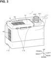
- FIG. 3 is a perspective external view of the air conditioner 1 from its rear.
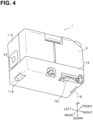
- FIG. 4 is a perspective external view of the air conditioner 1 from its bottom.
- FIG. 1 schematically shows a cross-section of the air conditioner 1 as viewed from the front. In FIG. 1 , directional terms, up, down, left, and right, are shown based on the air conditioner 1 placed in a normal usage mode. In Figs.
- the vertical direction indicates the up-down direction.
- a first horizontal direction indicates the left-right direction.
- a second horizontal direction indicates the front-rear direction.
- the air conditioner 1 is mounted on a vehicle, for example, a commercial vehicle such as a forklift or a truck, a towing vehicle, a lifting vehicle, a mini excavator car, or a golf cart.
- a vehicle for example, a commercial vehicle such as a forklift or a truck, a towing vehicle, a lifting vehicle, a mini excavator car, or a golf cart.
- the power of a main body of the air conditioner 1 may be turned on and off in conjunction with a key switch of an engine of the forklift. That is, the power of the air conditioner 1 may be turned on by turning on the engine of the forklift, and the power of the air conditioner 1 may be turned off by turning off the engine of the forklift.
- a housing 10 is made of resin or metal and shaped like a rectangular box, and includes a main body 11 and a door 12 that is openable and closable relative to the main body 11.
- the housing 10 forming a box has an upper surface, a lower surface, and side walls.
- the side walls include a first side wall 111, a second side wall 112, a third side wall 113, and a fourth side wall 114.
- the first side wall 111 corresponds to a rear side wall.
- the second side wall 112 corresponds to a front side wall.
- the third side wall 113 corresponds to a right side wall.
- the fourth side wall 114 corresponds to a left side wall.
- the first side wall 111 and the second side wall 112 face each other.
- the third side wall 113 and the fourth side wall 114 face each other.
- the third side wall 113 connects the first side wall 111 and the second side wall 112.
- the fourth side wall 114 connects the first side wall 111 and the second side wall 112.
- the first side wall 111 is constituted by a body-side first side wall 1111 and a door-side first side wall 1112.
- the door 12 is disposed above the main body 11 and is openable and closable relative to the main body 11.
- the door-side first side wall 1112 is connected to the body-side first side wall 1111 by two support portions 115.
- the support portions 115 for example, hinges can be used.
- a duct 431 for blowing out supply air is disposed in an upper surface of the housing 10.
- a water tank 8 is disposed beside the second side wall 112 of the housing 10.
- a tank base 116 for arranging the water tank 8 is positioned below the second side wall 112 of the housing 10.
- the water tank 8 is disposed on the tank base portion 116, thereby covering the second side wall 112.
- a drainage channel 781 for draining water from a drain pan 6, which will be described later, is provided in a lower portion of the tank base 116.
- the water tank 8 is detachably fitted to the housing 10.
- the water tank 8 has a gripping portion and can be removed from the housing 10.
- the water tank 8 has a water level confirmation window 82 in a side surface thereof. The user can visually recognize the amount of water remaining in the water tank 8 through the water level confirmation window 82.
- the housing 10 has a supply air inlet 42 for drawing in air in the space to be air-conditioned, and an exhaust air inlet 52. Further, the housing 10 has a supply air outlet 43 and an exhaust air outlet 53.
- the supply air inlet 42 is defined in the third side wall 113 of the housing 10.
- the exhaust air inlet 52 is defined in the door 12 forming a part of the housing 10.
- the supply air outlet 43 is defined in the upper surface of the housing 10 and communicates with the duct 431.
- the duct 431 is rotatable in a circumferential direction of the supply air outlet 43 and includes a wind direction adjusting plate 432 that adjusts the wind direction of the supply air blown out from the duct 431.
- the exhaust air outlet 53 is defined in the fourth side wall 114 of the housing 10.
- the air conditioner 1 includes the water tank 8 for storing water, and a cooling unit 20 including an evaporative filter 2 and a sensible heat exchanger 3, which are to be supplied with water from the water tank 8.
- the evaporative filter 2 is housed in an evaporative filter case 22.
- the sensible heat exchanger 3 is housed in a heat exchanger case 34. Details of the evaporative filter case 22 and the heat exchanger case 34 will be described later.
- the evaporative filter 2 lowers the ambient temperature using the heat of evaporation of the water supplied from the water tank 8, and cools the space to be air-conditioned.
- the sensible heat exchanger 3 lowers the ambient temperature using the sensible heat and the latent heat of the water supplied from the water tank 8, and cools the space to be air-conditioned.
- the sensible heat exchanger 3 is an example of a heat exchanger.
- the evaporative filter 2 is disposed downstream of the sensible heat exchanger 3 in a flow direction of the supply air. That is, the evaporative filter 2 is disposed between the sensible heat exchanger 3 and the supply air outlet 43.
- Air that has passed through the sensible heat exchanger 3 and the evaporative filter 2 undergoes two-stage cooling processes.
- the air is cooled by the sensible heat exchanger 3 and the evaporative filter 2, and is blown out through the supply air outlet 43 into the space to be air-conditioned as supply air. Further, when the air passes through the sensible heat exchanger 3, the air is cooled by the water supplied to the sensible heat exchanger 3, and then the air that has undergone sensible heat exchange with the supply air in the sensible heat exchanger 3 is blown outside the air conditioner 1 through the exhaust air outlet 53 as exhaust air.
- the supply air inlet 42 and the supply air outlet 43 communicate with each other.
- the supply air inlet 42 as an inlet for supply air and the supply air outlet 43 as an outlet for supply air define a supply-air flow passage 4 through which air that will be supply air flows.
- supply air flows into the supply-air flow passage 4 through the supply air inlet 42 and flows out through the supply air outlet 43.
- the supply air inlet 42 may be covered with a supply air dust collecting filter for collecting dust in the supply air drawn in through the supply air inlet 42.
- exhaust air flows into the exhaust-air flow passage 5 through the exhaust air inlet 52 and flows out through the exhaust air outlet 53.
- the exhaust air inlet 52 may be covered with an exhaust air dust collecting filter for collecting dust in the exhaust air drawn in through the exhaust air inlet 52.
- the supply air channel 31 is defined by stacked spaces communicating with each other from the inlet of the supply air channel 31 toward the outlet of the supply air channel 31.
- the sensible heat exchanger 3 has an inlet of the exhaust air channel 32 in its upper surface, and an outlet of the exhaust air channel 32 in its lower surface.
- the exhaust air channel 32 is defined by stacked spaces each extending from the inlet of the exhaust air channel 32 toward the outlet of the exhaust air channel 32.
- the residual water of the sensible heat exchanger 3 and the evaporative filter 2 unit are received by the drain pan 6 located below the sensible heat exchanger 3 and the evaporative filter 2, and the residual water is collected by being stored in the water storage space of the drain pan 6.
- the water collected in the drain pan 6 is supplied to the evaporative filter 2 unit and the sensible heat exchanger 3 via a supply water channel 7.
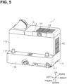
- FIG. 5 is a perspective external view of the air conditioner 1 from its front with the water tank 8 removed.
- the housing 10 has a tank base 116 for positioning the water tank 8, adjacent to the second side wall 112.
- the tank base 116 extends forward beyond the second side wall 112, creating a step between the tank base 116 and the second side wall 112.
- the tank base 116 has cylindrical bosses 117 on its upper surface. In the present embodiment, two bosses 117 are disposed on the upper surface of the tank base 116.
- a communication hole, which communicates with the replenishing water channel 9, is located between the two bosses 117. As described above, when the water tank 8 is disposed on the upper surface of the tank base 116, the bosses 117 are engaged in the recessed boss receiving portions 81 formed on the lower surface of the water tank 8.
- the boss receiving portions 81 are formed in a concave shape, so that the bosses 117 and the boss receiving portions 81 are engaged with each other.
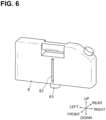
- the lower surface of the water tank 8 has a cylindrical outflow portion 83 protruding between the two boss receiving portions 81.
- the cylindrical outflow portion 83 has an internal space that functions as an outflow hole through which the water in the water tank 8 flows out.
- the water in the water tank 8 flows through the cylindrical outflow portion 83 into the replenishing water channel 9.
- the cylindrical outflow portion 83 may have a valve body for stopping the outflow of water from the water tank 8 when the water tank 8 is removed.
- the water tank 8 has, on its upper surface, an inflow hole used for adding water in the water tank 8.
- FIG. 8 is a side cross-sectional view of the air conditioner 1 with the water tank 8 attached.
- This side cross-sectional view shows the housing 10 as viewed from the third side wall 113.
- the water tank 8 and the water supply pump 76 for supplying water from the water tank 8 to the drain pan 6 are positioned differently from the sensible heat exchanger 3 and the drain pan 6 in the vertical direction and a direction perpendicular to a direction from the entrance to the supply air channel 31 in the sensible heat exchanger 3 toward the outlet therefrom.
- the water tank 8 and the water supply pump 76 located below the water tank 8 are located at different positions from the sensible heat exchanger 3 and the drain pan 6, which are arranged vertically.
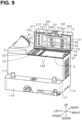
- FIG. 9 is an explanatory view of the air conditioner with the upper surface of the cooling unit 20 exposed by opening the door 12.
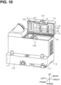
- FIG. 10 illustrates the air conditioner from which the cooling unit 20 is removed.
- FIG. 11 illustrates water supply devices in a state where the door 12 is closed.
- the housing 10 has the door 12 configured to be freely opened and closed. That is, the door 12 forms a part of the housing 10, and the upper surface of the door 12 forms a part of the upper surface of the housing 10.
- a front wall of the door 12 forms a part of the second side wall 112 of the housing 10, and includes a part of a lock mechanism 14 for fixing the door 12 to the main body 11 in a closed state.
- the lock mechanism 14 is released, and the door 12 rotates about the support portions 115 disposed on the first side wall 111 to be in an open state.
- the door 12 has a box shape, and the filter water supply device 21 and the heat exchanger water supply device 33 are disposed inside the door 12.
- the filter water supply device 21 and the heat exchanger water supply device 33 are fixed to the inside of the box-shaped door 12. Therefore, the filter water supply device 21 and the heat exchanger water supply device 33 change their positions or orientations relative to the cooling unit 20 in conjunction with opening or closing of the door 12.
- the filter water supply device 21 and the heat exchanger water supply device 33 are each an example of a water supply device.
- the filter water supply device 21 and the heat exchanger water supply device 33 are in a first position in which they face the upper surface of the cooling unit 20, in a perpendicular direction to the upper surface.
- the filter water supply device 21and the heat exchanger water supply device 33 are in a second position in which they are located away from the upper surface in a plane direction orthogonal to the perpendicular direction to the upper surface of the cooling unit 20.
- the filter water supply device 21 and the heat exchanger water supply device 33 that are fixed to the door 12 can be moved between the first position and the second position in conjunction with opening or closing of the door 12.
- the present embodiment shows, but is not limited to, that the filter water supply device 21 and the heat exchanger water supply device 33 are fixed to the door 12.
- the filter water supply device 21 and the heat exchanger water supply device 33 may not be fixed to the door 12, but may be disposed on an inner lid located between the door 12 and the main body 11.
- the filter water supply device 21 and the heat exchanger water supply device 33 configured as part of the inner lid can be in a first position or a second position according to the opened or closed state of the inner lid.
- the filter water supply device 21 and the heat exchanger water supply device 33 fixed to the door 12 are connected by the water supply device connection channel 74.
- two heat exchanger water supply devices 33 are disposed, and the downstream heat exchanger water supply device 33 in the flow direction of water in the supply water channel 7 and the filter water supply device 21 are connected by the water supply device connection channel 74.
- These two heat exchanger water supply devices 33 are connected by the second supply water channel 72, and the second supply water channel 72 is bent in an L shape and connected to one end of the connecting supply water channel 73.
- the other end of the connecting supply water channel 73 is connected to the first supply water channel 71 disposed along the first side wall 111 of the housing 10, more specifically, the body-side first side wall 1111.
- the connecting supply water channel 73 is flexible and relieves or absorbs stress generated when the door 12 is opened and closed.
- the heat exchanger water supply devices 33 are constructed from, for example, rectangular parallelepiped hollow pipes made of resin or metal, and have a plurality of nozzles 331 with holes 332 formed in their lower surfaces, which face the sensible heat exchanger 3.
- the second supply water channel 72 passes over the heat exchanger water supply devices 33 and is connected to communication ports provided in upper portions of the heat exchanger water supply devices 33.
- the water flowing into the second supply water channel 72 from the connecting supply water channel 73 is supplied to the heat exchanger water supply devices 33 via the communication ports provided in the upper portions of the heat exchanger water supply devices 33.
- the water supplied to the heat exchanger water supply devices 33 falls in drops onto the upper surface of the sensible heat exchanger 3 from the holes 332 of the plurality of nozzles 331located in the lower surfaces.
- the upper surface of the sensible heat exchanger 3 forms a part of the upper surface of the cooling unit 20.
- the filter water supply device 21 is constructed from, for example, a rectangular parallelepiped hollow pipe made of resin or metal, and has a plurality of nozzles 211 with holes 212 formed in a lower surface, which faces the evaporative filter 2. Further, the filter water supply device 21 has a hole in its right surface, that is, adjacent to the side surface of the heat exchanger water supply device 33. The filter water supply device 21 is positioned, in the up-down direction, at the same height as the water supply device connection channel 74, which is connected to the communication port in the side surface of the filter water supply device 21. Water flowing from the second supply water channel 72 into the water supply device connection channel 74 is supplied to the filter water supply device 21 via the communication port in the side surface of the filter water supply device 21.
- the water supplied to the filter water supply device 21 falls in drops onto the upper surface of the evaporative filter 2 from the holes 212 of the plurality of nozzles 211 in the lower surface.
- the upper surface of the evaporative filter 2 forms the other part of the upper surface of the cooling unit 20.
- the upper surface of the sensible heat exchanger 3 and the upper surface of the evaporative filter 2 constitute the upper surface of the cooling unit 20.
- the upper surface of the cooling unit 20 is an example of a surface of the cooling unit.
- the filter water supply device 21 and the heat exchanger water supply device 33 are connected in series by the water supply device connection channel 74, and the water supply device connection channel 74 may have an orifice 741 to be described later.
- the volumetric flow rate by the filter water supply device 21 can be reduced compared to the volumetric flow rate by the heat exchanger water supply device 33.
- the flow rate adjustment in the filter water supply device 21 and the heat exchanger water supply device 33 is not limited to using the orifice 741 of the water supply device connection channel 74. Instead, the flow rate can also be adjusted by making the hole diameter of the nozzles 211 of the filter water supply device 21 smaller than the hole diameter of the nozzle of the heat exchanger water supply device 33.
- the second supply water channel 72, the heat exchanger water supply devices 33, the water supply device connection channel 74, and the filter water supply device 21 are arranged in this order in the flow direction of supply water inside the box-shaped door 12.
- the internal space of the box-shaped door 12 is divided into a region in which the filter water supply device 21 is disposed and a region in which the heat exchanger water supply devices 33 are disposed.
- the region in which the heat exchanger water supply devices 33 are disposed communicates with the exhaust air inlet 52 formed in the upper surface of the door 12, thereby forming a part of the exhaust-air flow passage 5.
- the exhaust sucked air drawn in from the exhaust air inlet 52 passes through the region where the heat exchanger water supply devices 33 are disposed inside the door 12, and then flows into the exhaust air channel 32 of the sensible heat exchanger 3.
- the heat exchanger water supply devices 33 when fixed to the door 12, may be held by, for example, a rectangular tubular frame body. In this case, the inside of the frame body that holds the heat exchanger water supply devices 33 forms a part of the exhaust-air flow passage 5.
- the water supply device connection channel 74 for connecting the heat exchanger water supply device 33 and the filter water supply device 21 is arranged by passing through a through-hole in the frame body.
- the exhaust air drawn in from the exhaust air inlet 52 formed in the door 12 does not flow into the region. That is, when the housing 10 is viewed in a plan view from above, the exhaust air inlet 52 formed in the door 12 is disposed at a position shifted from the filter water supply device 21 and overlapping the heat exchanger water supply devices 33.
- the filter water supply device 21 is fixed to the door 12 by a fixing member 122 to which a second sealing member 123 is attached.
- the second sealing member 123 comes into contact with the upper end of a columnar rib 221 of the evaporative filter case 22, thereby ensuring the sealing property in the supply-air flow passage 4. Details of the evaporative filter case 22 and other elements will be described later.
- the structural member 441 defining the first intermediate supply-air flow passage 44 is U-shaped in a cross-sectional view, and has two upper end portions. Among the two upper end portions, the end surface of the upper end portion located adjacent to the heat exchanger case 34 is in contact with the lower surface of the first flange 362 of the supply air outlet-side frame 36 of the heat exchanger case 34. Among the two upper end portions, the end surface of the upper end portion located adjacent to the evaporative filter case 22 is in contact with the lower surface of the second flange 222 of the filter frame 224 of the evaporative filter case 22. Further, the outer surface of the upper end portion located adjacent to the evaporative filter case 22 is in contact with the annular rib 225 formed on the filter frame 224.
- the water level sensor 63 is disposed at a position different from the evaporative filter 2 in a direction from the supply air inlet to the supply air outlet of the evaporative filter 2. That is, in a plan view of the air conditioner 1 as viewed from above, the water level sensor 63 is disposed differently from the evaporative filter 2, and is disposed upstream of the supply air inlet of the evaporative filter 2 in the flow direction of the supply air.
- the water level sensor 63 is located downstream of the sensible heat exchanger 3 and upstream of the evaporative filter 2 in the direction from the supply air inlet to the supply air outlet of the sensible heat exchanger 3.
- the first intermediate supply-air flow passage 44 is located between the sensible heat exchanger 3 and the evaporative filter 2, and the water level sensor 63 is disposed directly below the first intermediate supply-air flow passage 44.
- the water level sensor 63 is disposed away from a position immediately below the sensible heat exchanger 3 and the evaporative filter 2, thereby reducing the possibility that water dripping from the sensible heat exchanger 3 and the evaporative filter 2 directly contacts the water level sensor 63. This ensures the detection accuracy of the water level sensor 63.
- FIG. 27 illustrates how a drain pan filter 75 is attached.
- FIG. 28 illustrates how the drain pan filter 75 is detached.
- the supply water channel 7 is connected to the bottom hole 611 in the bottom surface 61 of the drain pan 6.
- One end of the supply water channel 7 connected to the bottom hole 611 is located below the bottom surface 61 of the drain pan 6.
- the drain pan filter 75, the water supply pump 76, and the flow rate sensor 77, which are connected to the middle of the path in the supply water channel 7, are also located below the bottom surface 61 of the drain pan 6.
- the drain pan filter 75 has a cylindrical shape, and accommodates a cylindrical filter body inside.
- the drain pan filter 75 can collect dirt such as dust or impurities contained in the water flowing through the supply water channel 7, thereby removing the dirt. This can reduce clogging of the filter water supply device 21 and the heat exchanger water supply devices 33, and also reduce contamination of the sensible heat exchanger 3 and the evaporative filter 2.
- the cylindrical drain pan filter 75 has a large-diameter portion in which the filter body is stored, and a small-diameter portion located downstream of the large-diameter portion in the flow direction of supply water.
- the small-diameter portion has an annular packing that reduces the possibility of flowing dust or similar particles collected by the filter body into the supply water channel 7.
- the internal diameter (d1) of the large-diameter portion is greater than the internal diameter (d2) of the small-diameter portion, i.e., d1 > d2, and the path length (11) of the large-diameter portion is greater than the path length (12) of the small-diameter portion, i.e., 11 > 12.
- the drain pan filter 75 is detachable from the front wall of the tank base portion 116 parallel to the second side wall 112. More specifically, the front wall of the tank base portion 116 has a hole for the drain pan filter 75, and the drain pan filter 75 is inserted into the hole to be located in the middle of the path of the supply water channel 7.
- the drain pan filter 75 includes a knob portion having a cross shape, for example, at an end surface of the drain pan filter 75, and a cap may be attached to cover the knob portion. The drain pan filter 75 thus configured allows for efficient mounting and removal.
- the outer surface of the front wall of the tank base portion 116 constitutes a surface of the housing 10.
- the drain pan filter 75 not only the drain pan filter 75, but also the water tank 8 and the drainage channel 781 are located adjacent to the second side wall 112.
- a worker who performs maintenance on the air conditioner 1 can attach and detach the water tank 8, attach and detach the drain pan filter 75, and operate the on-off valve or cock of the drainage channel 781 from the second side wall 112.
- This arrangement allows the maintenance work to be performed efficiently.
- the lock mechanism 14 is exposed, and the operation portion 141 of the lock mechanism 14 can be operated from the second side wall 112. Accordingly, a series of maintenance operations including opening and closing of the door 12, and further removing and attaching the evaporative filter case 22 and the heat exchanger case 34 can be all performed from the second side wall 112. In this manner, the parts required for the maintenance work are concentrated adjacent to the second side wall 112, which can function as a service surface for the worker to face during the maintenance work.
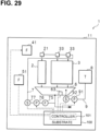
- FIG. 29 is a block diagram illustrating functional components in the air conditioner 1.
- the air conditioner 1 has a substrate 100 including a controller 101.
- the substrate 100 is populated with a microcomputer including a memory and an MPU.
- the microcomputer functions as the controller 101 that controls driving of the water supply pump 76, the tank pump 91, and other electrical components.
- the memory stores a program executed by the controller 101.
- the substrate 100 may be, for example, disposed on an outer surface of a flow path wall defining the exhaust-air flow passage 5, and may be thermally connected to the flow path wall to be cooled by the exhaust air flowing through the exhaust-air flow passage 5.
- the supply air fan 41, the exhaust air fan 51, the water level sensor 63, the water supply pump 76, the flow rate sensor 77, the tank pump 91, and the tank flow rate sensor 92, which are electrical components included in the air conditioner 1, are communicably connected to the controller 101 on the substrate 100 via a communication line.
- the water level sensor 63 is, for example, a float sensor, and outputs, to the controller 101, a water level signal, which is a signal related to the detection result of the water level of the water stored in the drain pan 6.
- the flow rate sensor 77 and the tank flow rate sensor 92 are, for example, impeller type or clamp-on type sensors.
- the flow rate sensor 77 outputs, to the controller 101, a first flow rate signal, which is a signal related to a detection result of the flow rate of the water flowing through the supply water channel 7.
- the tank flow rate sensor 92 outputs, to the controller 101, a second flow rate signal, which is a signal related to the detection result of the flow rate of the water flowing through the replenishing water channel 9.
- the controller 101 determines whether the water level of the drain pan 6 is lower than or equal to a predetermined value based on a water level signal which is a signal received from the water level sensor 63. When determining that the water level is equal to or lower than the predetermined value, the controller 101 drives the tank pump 91, thereby replenishing the drain pan 6 with water from the water tank 8.
- the controller 101 may use the first flow rate signal from the flow rate sensor 77 and the second flow rate signal from the tank flow rate sensor 92 to detect a failure or determine whether the water tank 8 is empty based on the first flow rate signal.
- the sensible heat exchanger 3 is used as the heat exchanger, but the heat exchanger may be a total heat exchanger.
- the door 12 is openable and closable relative to the main body 11 by rotating about the support portions 115, which are hinges.
- the door 12 may be slidable back and forth or right and left.
- the door 12 may be configured by a lid that is detachable from the main body 11.
- the lid has hooks on both sides, and are configured to be inserted into the holes in the main body 11. As the hooks are pulled out of position, the lid is raised, and the sensible heat exchanger 3 is in a state where it can be replaced.
- the lid is connected to the main body only by the connecting supply water channel 73 in such a state that the hooks are out of position.
- the housing 10 includes the main body 11 and the lid connected to the main body 11, the upper surface, which is a surface, of the cooling unit 20 disposed inside the main body 11 is covered by the lid.
- the water supply device for supplying water to the upper surface, the supply water channel 7 located inside the main body 11, and the flexible connecting supply water channel 73 for connecting the water supply device and the supply water channel 7 are located. Since the connecting supply water channel 73 is flexible, maintenance work such as replacement of the cooling unit 20 can be performed without completely removing the lid.
- the air conditioner 1 includes the cooling unit 20 and the water supply device that supplies water to a surface of the cooling unit 20.
- the cooling unit 20 includes the supply air channel 31 and the exhaust air channel 32.
- the water supply device is movable between a first position in which the water supply device faces the surface in a perpendicular direction to the surface and a second position in which the water supply device is located away from the surface in a planar direction orthogonal to the perpendicular direction. Therefore, during operation of the air conditioner 1, the water supply device in the first position can supply water to the cooling unit 20. Then, when maintenance work of the air conditioner 1 is performed, the water supply device is moved from the first position to the second position.
- the water supply device supplies water to at least a part of the surface of the cooling unit. Further, the surface of the cooling unit may be a side surface of the cooling unit.
- the air conditioner 1 includes the housing 10 that houses the cooling unit 20.
- the housing 10 includes the door 12 that is located above the cooling unit 20 and can be opened and closed, and the water supply device is fixed to the door 12.
- the water supply device is configured to move between a first position and a second position in conjunction with opening or closing of the door 12. Specifically, the water supply device is in the first position when the door 12 is closed, and in the second position when the door 12 is opened.
- the air conditioner 1 includes the supply water channel 7 connected to the water supply device.
- the supply water channel 7 includes a first supply water channel 71 routed along the first side wall 111, a second supply water channel 72 fixed to the door 12 and connected to the water supply device, and a connecting supply water channel 73 connecting the first supply water channel 71 and the second supply water channel 72.
- the connecting supply water channel 73 is flexible.
- the connecting supply water channel 73 deforms or experiences stress due to the opening or closing of the door 12, but can cope with the deformation and stress within its elastic range due to its flexibility. This flexibility improves resistance of the connecting supply water channel 73 to the repeated opening and closing of the door 12.
- the housing 10 includes the second side wall 112 that faces the first side wall 111, the third side wall 113, and the fourth side wall 114.
- the third side wall 113 connects the first side wall 111 and the second side wall 112.
- the fourth side wall 114 connects the first side wall 111 and the second side wall 112 and faces the third side wall 113.
- the first connection portion 731 that connects the first supply water channel 71 and the connecting supply water channel 73 is located at a position closer to the third side wall 113 than to the fourth side wall 114.
- the second connection portion 732 that connects the second supply water channel 72 and the connecting supply water channel 73 is located at a position closer to the fourth side wall 114 than to the third side wall 113.
- Such an arrangement configuration allows for a relatively longer path length of the connecting supply water channel 73, and results in a smaller amount of deformation per unit length due to the opening and closing of the door 12. This improves the resistance of the connecting supply water channel 73 to the repeated opening and closing of the door 12.
- the length of the connecting supply water channel 73 is longer than the length of the door 12 in the first horizontal direction, which is orthogonal to the vertical direction and extending from the third side wall 113 to the fourth side wall 114. This allows for a relatively longer path length of the connecting supply water channel 73, and results in a smaller amount of deformation per unit length due to the opening and closing of the door 12. This improves the resistance of the connecting supply water channel 73 to the repeated opening and closing of the door 12.
- the connecting supply water channel 73 is located offset relative to the cooling unit 20 in the second horizontal direction that is orthogonal to the vertical direction and the first horizontal direction.
- the connecting supply water channel 73 can be located at a position deviated from a flow passage when water is supplied from the water supply device to the cooling unit 20.
- the cooling unit 20 includes the sensible heat exchanger 3 including the supply air channel 31 and the exhaust air channel 32, and the evaporative filter 2 communicating with supply air channel 31.
- the water supply device includes the heat exchanger water supply device 33 for supplying water to the exhaust air channel 32 of the sensible heat exchanger 3, and the filter water supply device 21 for supplying water to the evaporative filter 2. Therefore, water can be individually supplied to the sensible heat exchanger 3 and the evaporative filter 2 from the heat exchanger water supply devices 33 and the filter water supply device 21.
- the supply water channel 7 includes the water supply device connection channel 74 for connecting the heat exchanger water supply device 33 and the filter water supply device 21, and the second supply water channel 72 is connected to the heat exchanger water supply devices 33.
- the heat exchanger water supply devices 33 can be disposed upstream of the filter water supply device 21 in the flow direction of the supplied water, and water can be preferentially supplied to the heat exchanger water supply devices 33.
- the water supply device connection channel 74 has, for example, the orifice 741, and is structured such that the internal diameter of at least a portion of the water supply device connection channel 74 is smaller than the internal diameter of any portion of the second supply water channel 72. That is, the flow path resistance of the water supply device connection channel 74 is greater than the flow path resistance of the second supply water channel 72. This can reduce the amount of water supplied to the filter water supply device 21, which is located in a downstream portion of the water supply device connection channel 74 in the flow direction of supply water, compared to the amount of water supplied to the heat exchanger water supply device 33, allowing the water to be preferentially supplied to the heat exchanger water supply devices 33.
- the air conditioner 1 includes the housing 10, the cooling unit 20, the water supply device, the supply water channel 7 disposed inside the main body 11, and the connecting supply water channel 73 having flexibility.
- the housing 10 includes the main body 11 and the door 12 connected to the main body 11.
- the cooling unit 20 is disposed inside the main body 11 and has a surface to be covered by the door 12.
- the water supply device is located between the door 12 and the surface of the cooling unit 20, and supplies water to the surface of the cooling unit 20.
- the connecting supply water channel 73 connects the water supply device and the supply water channel 7.
- the connecting supply water channel 73 deforms or experiences stress.
- the connecting supply water channel 73 can cope with the deformation and stress within its elastic range due to its flexibility. This improves resistance of the connecting supply water channel 73 to the repeated opening and closing of the door 12.
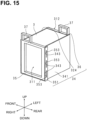
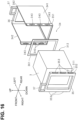
- the first portion includes a first wall 341 that is parallel to the supply air channel 31 and the exhaust air channel 32, and a supply air inlet-side frame 35 that faces the supply air inlet surface 311 and to which the first wall 341 is connected.
- the second portion includes a second wall 342 that faces the first wall 341 and is connected to the supply air inlet-side frame 35, and the supply air outlet-side frame 36 that faces the supply air outlet surface 312 and is connected to the first wall 341 and the second wall 342. Since the first portion has a shape different from that of the second portion, the first portion and the second portion have bilaterally asymmetric shapes. Thus, the heat exchanger case 34 can be prevented from being inserted into the housing 10 with its orientation reversed.
- the heat exchanger case 34 may include a facing portion including portions facing each other, and one portion and the other portion constituting the facing portion may have different shapes. As described above, since the facing portion of the heat exchanger case 34 is formed such that one portion and the other portion have different shapes, meaning they are bilaterally asymmetric, the heat exchanger case 34 can be prevented from being inserted into the housing 10 with its orientation reversed.
- the supply air inlet-side frame 35 has a shape different from that of the supply air outlet-side frame 36. As described above, since the supply air inlet-side frame 35 and the supply air outlet-side frame 36 forming the facing portion of the heat exchanger case 34 have different shapes, the heat exchanger case 34 can be prevented from being inserted into the housing 10 with its orientation reversed.
- the first wall 341 has a shape different from that of the second wall 342.
- the heat exchanger case 34 can be prevented from being inserted into the housing 10 with its orientation reversed.
- the air conditioner 1 includes the sealing member 361 that is in close contact with the inner surface of the supply air outlet-side frame 36 and the outlet surface of the supply air channel 31 of the sensible heat exchanger 3. That is, the sealing member 361 is located between the outlet surface of the supply air channel 31 and the inner surface of the supply air outlet-side frame 36.
- the sealing member 361, located in this manner, ensures the sealing performance in the supply-air flow passage 4, thus reducing the possibility of non-cooled air, which is, air that has not passed through the sensible heat exchanger 3, mixing with the supply air. This can further reduce the possibility that the supply air bypasses the supply air channel 31 of the sensible heat exchanger 3 without passing through the supply air channel 31.
- the sealing member 361 is fixed to the supply air outlet-side frame 36. This can improve the sealing performance in the supply-air flow passage 4 compared with a case where the sealing member 361 is integrated with the sensible heat exchanger 3.
- the supply air outlet-side frame 36 may be integrally molded with the heat exchanger case 34.
- the supply air outlet-side frame 36 and the sealing member 361, which are integrally fixed to the main body of the heat exchanger case 34, can improve the sealing performance at the outlet surface of the supply air channel 31 of the sensible heat exchanger 3 in the supply-air flow passage 4.
- the supply-air flow passage 4 a portion of which is constituted by the supply air channel 31 of the sensible heat exchanger 3, is located inside the housing 10.
- the supply-air flow passage 4 includes a first intermediate supply-air flow passage 44 located downstream of the supply air outlet surface 312having the outlet of the supply air channel 31 of the sensible heat exchanger 3, in a first direction from the supply air inlet surface toward the supply air outlet surface, that is, in the supply air direction.
- the supply air outlet-side frame 36 has a first flange 362 protruding downstream in the first direction.
- the first flange 362 is located so as to overlap the first intermediate supply-air flow passage 44 in the supply air direction. Therefore, the sealing performance in the first intermediate supply-air flow passage 44 can be improved. This can reduce the possibility of non-cooled air entering the supply-air flow passage 4 located downstream of the sensible heat exchanger 3, thereby reducing the possibility of air that has not passed through the sensible heat exchanger 3 mixing with the supply air.
- the supply air inlet-side frame 35 is detachably attached to the heat exchanger case 34. That is, while the supply air outlet-side frame 36 is integral with the main body of the heat exchanger case 34, the supply air inlet-side frame 35 is separable from the main body of the heat exchanger case 34.
- the supply air inlet-side frame 35 is thus detachably attached to the main body of the heat exchanger case 34, thereby enabling removal of the sensible heat exchanger 3 housed in the heat exchanger case 34 from the side on which the supply air inlet-side frame 35 has been detached.
- the sensible heat exchanger 3 housed in the heat exchanger case 34 can be replaced efficiently.
- the sealing member 361 can be prevented from being damaged when the sensible heat exchanger 3 is attached to or detached from the heat exchanger case 34.
- the reverse insertion prevention structure 351 is provided to the first wall 341 and the second wall 342 of the heat exchanger case 34.
- the reverse insertion prevention structure 351 is constituted by end edges of the first wall 341 and the second wall 342, which are located adjacent to the supply air inlet-side frame 35. Due to the reverse insertion prevention structure 351 constituted as described above, the first wall 341 and the second wall 342 can have different shapes. This can prevent the heat exchanger case 34 from being inserted into the housing 10 with its orientation reversed.
- the first wall 341 and the second wall 342 have recesses 343 at their end edges, which constitute the reverse insertion prevention structure 351.
- the recesses 343 are engageable with the protrusions 353 on the outer edges 352 of the supply air inlet-side frame 35, thereby forming the reverse insertion prevention structure 351 on the supply air inlet-side frame 35 side.
- the cooling unit 20 includes the evaporative filter 2.
- the air conditioner 1 includes the evaporative filter case 22 attachable to and detachable from the housing 10 in a state of housing the evaporative filter 2. Therefore, the evaporative filter case 22 is removed from the housing 10, thereby allowing efficient maintenance work such as replacement of the evaporative filter 2.
- the air conditioner 1 further includes a filter water supply device 21 that supplies water to the evaporative filter 2.
- the evaporative filter case 22 has the columnar rib 221 extending from its upper surface toward the filter water supply device 21. Water supplied from the filter water supply device 21 passes through the space surrounded by the columnar rib 221 and is supplied to the evaporative filter 2.
- the space surrounded by the columnar rib 221 is used as a channel for water supplied from the filter water supply device 21 as described above, thereby allowing water to be reliably guided to and efficiently supplied to the evaporative filter 2 located in the evaporative filter case 22.
- the housing 10 has a door 12 that can be opened and closed, and the filter water supply device 21 is fixed to the door 12 by the fixing member 122.
- the second sealing member 123 is attached to the fixing member 122.
- the second sealing member 123 is in contact with an upper end portion of the columnar rib 221 when the door 12 is in the closed state.
- the inner space of the columnar rib 221 serving as the channel for water supplied from the filter water supply device 21 to the evaporative filter 2 communicates with the supply-air flow passage in the evaporative filter 2.
- the upper end portion of the columnar rib 221 comes into contact with the second sealing member 123 located on the inner surface of the door 12, thereby reducing the possibility of non-cooled air mixing with the supply air passing through the evaporative filter 2. This can further reduce the possibility of the supply air leaking outside the supply-air flow passage 4 from above the columnar rib 221.
- the evaporative filter case 22 includes the second flange 222 that protrudes in the first direction, that is, upstream in the supply air direction. More specifically, the second flange 222 of the evaporative filter case 22 extends in a direction opposite to the flow of the supply air in the path direction of the first intermediate supply-air flow passage 44. The second flange 222 of the evaporative filter case 22 is located overlapping the first intermediate supply-air flow passage 44 in the first direction, thus improving the sealing performance in the first intermediate supply-air flow passage 44. This reduces the possibility of non-cooled air entering the supply-air flow passage 4 located upstream of the evaporative filter 2.
- the evaporative filter case 22 for housing the evaporative filter 2 has a rotatable handle 223.
- the rotatable handle 223 By using the rotatable handle 223 in this manner, the evaporative filter case 22 can be easily removed from the housing 10.
- the handle 223 rotated to a gripping position allows for easily removal of the evaporative filter case 22 from the housing 10. That is, the rotatable handle 223 can improve the ease of removing the evaporative filter case 22 without increasing the size of the housing 10 of the air conditioner 1.
- the handle 223 of the evaporative filter case 22 is rotatable, and is located outside the wall constituting the columnar rib 221 when the door 12 is in the closed state. Accordingly, when the internal space of the columnar rib 221 in the evaporative filter case 22 serves as a channel for water supplied from the filter water supply device 21 to the evaporative filter 2, the handle 223 can be located offset from the channel.
- the heat exchanger case 34 has handles 37. More specifically, each of the supply air inlet-side frame 35 and the supply air outlet-side frame 36 of the heat exchanger case 34 includes a handle 37.
- the heat exchanger case 34 can be easily removed from the housing 10 by gripping the handles 37 on the supply air inlet-side frame 35 and the supply air outlet-side frame 36.
- the door 12 forming part of the housing 10 has the exhaust air inlet 52 for sucking exhaust air and the exhaust-air flow passage 5.
- the handles 37 of the heat exchanger case 34 are positioned outside the exhaust-air flow passage 5 formed in the door 12, thus reducing ventilation resistance in the exhaust-air flow passage 5.
- the air conditioner 1 includes the cooling unit 20, the water supply device that supplies water to the cooling unit 20, the drain pan 6, the supply water channel 7, the water tank 8 that stores water, and the replenishing water channel 9.
- the cooling unit 20 includes the evaporative filter 2 and the sensible heat exchanger 3.
- the water supply device includes the filter water supply device 21 for supplying water to the evaporative filter 2 and a heat exchanger water supply device 33 for supplying water to the sensible heat exchanger 3.
- the drain pan 6 receives water dripping from the cooling unit 20.
- the supply water channel 7 connects the drain pan 6 and the water supply device.
- the replenishing water channel 9 connects the water tank 8 and the drain pan 6.
- the water supply device is connected to the bottom hole 611 in the bottom surface 61 of the drain pan 6 via the supply water channel 7.
- the water tank 8 is connected to the water supply hole 621 in the wall surface 62 of the drain pan 6 via the replenishing water channel 9.
- the water supply hole 621 in the wall surface 62 is positioned above the bottom hole 611 in the bottom surface 61 in the vertical direction. Therefore, water supplied through the water supply hole 621 can be temporarily stored in the drain pan 6.
- the stored water can be directly supplied to the filter water supply device 21 and the heat exchanger water supply devices 33 through the bottom hole 611.
- the drain pan 6 has a suitable structure to facilitate the process. This can reduce the likelihood of water leakage from the drain pan 6 compared with a case where a separate water storage tank is disposed in the supply water channel 7 between the drain pan 6 and the water supply device. In addition, this eliminates the need for the provision of a separate water storage tank in the supply water channel 7 between the drain pan 6 and the water supply device, thereby preventing any increase in the physical size and weight of the product.
- the air conditioner 1 includes the water level sensor 63.
- the water level sensor 63 is disposed in the internal space that is a water storage space of the drain pan 6 having a box shape.
- the water level sensor 63 is disposed at a position offset from a perpendicular line to the cross section of the water supply hole 621 in the side surface of the drain pan 6.
- the water level sensor 63 is disposed at a position offset from a water discharge direction in which water is supplied from the water supply hole 621.
- the water level sensor 63 is fixed to the bottom plate of the drain pan 6 using the sensor fixing member 64.
- the sensor fixing member 64 has, for example, a box shape and includes a wall portion 641.
- the wall portion 641 is located between the water level sensor 63 and the water supply hole 621. Therefore, even if water supplied from the water supply hole 621 is partially ejected in the direction of the water level sensor 63, it is blocked by the wall portion 641 of the sensor fixing member 64. Thus, water supplied from the water supply hole 621 can be prevented from coming into contact with the water level sensor 63, thereby reducing erroneous detections by the water level sensor 63 and ensuring the detection accuracy of the water level.
- this structure can prevent any increase in the number of components compared with a case where, for example, a baffle plate, separate from the sensor fixing member 64 is used to exhibit the same function as that of the wall portion 641, thus reducing product costs, weight, and size by saving space.
- the cooling unit 20 includes the sensible heat exchanger 3 having the supply air channel 31 and the exhaust air channel 32.
- the sensible heat exchanger 3 has the supply air inlet surface 311 with the inlet of the supply air channel 31, and the supply air outlet surface 312 with the outlet of the supply air channel 31.
- the water level sensor 63 is fixed to the bottom plate of the drain pan 6, and the drain pan 6 is positioned below the sensible heat exchanger 3. Therefore, the water level sensor 63 is also positioned below the sensible heat exchanger 3.
- the water level sensor 63 is located downstream of the sensible heat exchanger 3 in the first direction from the supply air inlet surface 311 toward the supply air outlet surface 312 in the sensible heat exchanger 3.
- the water level sensor 63 is disposed away from a position immediately below the sensible heat exchanger 3.
- the position immediately below the sensible heat exchanger 3 is a position immediately below the outlet of the exhaust air channel 32 of the sensible heat exchanger 3, and water that has not been evaporated drips from the outlet of the exhaust air channel 32. Since the water level sensor 63 is positioned downstream of the sensible heat exchanger 3 in the direction from the inlet to the outlet of the supply air channel 31, water dripping from the outlet of the exhaust air channel 32 is received by the drain pan 6 without coming into contact with the water level sensor 63.
- water level sensor 63 By positioning the water level sensor 63 in this manner, water dripping from the outlet of the exhaust air channel 32 of the sensible heat exchanger 3 can be prevented from reaching the water level sensor 63, thereby reducing erroneous detections by the water level sensor 63 and ensuring the detection accuracy of the water level.
- the cooling unit 20 includes the evaporative filter 2.
- the evaporative filter 2 has a filter inlet surface 201 in which an inlet for supply air is formed, and a filter outlet surface 202 in which an outlet for supply air is formed.
- the water level sensor 63 is fixed to the bottom plate of the drain pan 6, and the drain pan 6 is positioned below the evaporative filter 2. Therefore, the water level sensor 63 is also positioned below the evaporative filter 2.
- the water level sensor 63 is disposed at a position different from that of the evaporative filter 2 in the flow direction of the supply air passing through the evaporative filter 2. That is, the water level sensor 63 is disposed away from a position immediately below the evaporative filter 2.
- the position immediately below the evaporative filter 2 corresponds to a position where water that has not been evaporated at the evaporative filter 2 drips. Since the water level sensor 63 is at a position different from the evaporative filter 2 in the flow direction of the supply air passing through the evaporative filter 2, the water dripping from below the evaporative filter 2 is received by the drain pan 6 without coming into contact with the water level sensor 63. By positioning the water level sensor 63 in this manner, water dripping from the evaporative filter 2 can be prevented from reaching the water level sensor 63, thereby reducing erroneous detections by the water level sensor 63 and ensuring the detection accuracy of the water level.
- the water level sensor 63 is fixed to the bottom plate of the drain pan 6, and the drain pan 6 is positioned below the evaporative filter 2 and the sensible heat exchanger 3. Therefore, the water level sensor 63 is also positioned below the evaporative filter 2 and the sensible heat exchanger 3. In addition, the water level sensor 63 is positioned between the sensible heat exchanger 3 and the evaporative filter 2, which are disposed along the flow direction of the supply air. That is, the water level sensor 63 is disposed away from a position immediately below the sensible heat exchanger 3 and the evaporative filter 2.
- water dripping from both of the sensible heat exchanger 3 and the evaporative filter 2 can be prevented from coming into contact with the water level sensor 63, thereby reducing erroneous detections by the water level sensor 63 and ensuring the detection accuracy of the water level.
- the water supply pump 76 and the drain pan filter 75 are disposed in the supply water channel 7. Water stored in the drain pan 6 is pumped up by the water supply pump 76.
- the drain pan filter 75 is disposed between the water supply pump 76 and the bottom hole 611 of the drain pan 6 in the supply water channel 7. Therefore, the water stored in the drain pan 6 passes through the drain pan filter 75 before reaching the water supply pump 76. Even when the water stored in the drain pan 6 contains dirt such as dust and impurities, the drain pan filter 75 can collect such dirt. That is, it can remove dirt from the water recirculated through the supply water channel 7 and the drain pan 6, that is, the water which is reused by being circulated.
- both the drain pan filter 75 and the water tank 8 are disposed adjacent to the same surface of the housing 10, that is, the second side wall 112, and are detachably attached to the surface of the housing 10.
- an operator of the air conditioner 1 or a worker who performs maintenance work can remove the drain pan filter 75 and the water tank 8 from the same surface that is the second side wall 112 of the housing 10. This facilitates efficient operations.
- the tank pump 91 is disposed in the replenishing water channel 9.
- the water tank 8 and the tank pump 91 are disposed at positions different from those of the sensible heat exchanger 3 and the drain pan 6 in the vertical direction and the direction perpendicular to the flow direction of the supply air passing through the sensible heat exchanger 3. This allows the water tank 8 and the water supply pump 76 to be vertically arranged and disposed beside the sensible heat exchanger 3 and the drain pan 6, that is, in front of the sensible heat exchanger 3 and the drain pan 6 in the present embodiment. This arrangement maintains a low overall height for the housing 10 of the air conditioner 1.
- the housing 10 has bosses 117 on the outer wall thereof.
- the water tank 8 includes boss receiving portions 81 having a hole shape and corresponding to the bosses 117.
- the boss receiving portions 81 of the water tank 8 are engaged with the bosses 117 of the housing 10.
- the water tank 8 can be efficiently positioned when attached to the housing 10.
- the water tank may have a cylindrical boss on its lower surface, and the housing may have a boss receiving portion having a hole shape and corresponding to the boss.
- the heat exchanger inclined surface portion 381 is inclined such that a distance between the heat exchanger inclined surface portion 381 of the first wall 341 and the side surface of the sensible heat exchanger 3 facing the first wall 341 decreases from the upper side toward the lower side.
- the heat exchanger inclined surface portion 381 is wider at its upper end, and the upper end of the heat exchanger inclined surface portion 381 and the side surface of the sensible heat exchanger 3 define an insertion portion where the distal end portion of the heat exchanger water receiver 131 is inserted.
- the inner surface of the first wall 341 and the side surface of the sensible heat exchanger 3 define a heat exchanger drainage channel 382. That is, the heat exchanger drainage channel 382 includes the heat exchanger inclined surface portion 381 and a bottom wall hole 384 in the bottom wall 383 of the heat exchanger case 34.
- the heat exchanger case 34 includes a frame-shaped bottom wall 383 connected to the supply air inlet-side frame 35, the supply air outlet-side frame 36, the first wall 341, and the second wall 342.
- the bottom wall 383 has a triangular hole, for example, which corresponds to a bottom wall hole 384.
- At least one bottom wall hole 384 is formed at a connection portion with any one of the first wall 341, the second wall, the supply air inlet-side frame 35, or the supply air outlet-side frame 36. That is, it is located at any one of four corners or angular portions of the bottom wall 383, which has a rectangular frame shape.
- the bottom wall hole 384 is formed, for example, at each of two corners located at both ends of a connection portion with the supply air inlet-side frame 35.
- the bottom wall 383 of the heat exchanger case 34 has the bottom wall hole 384 in the vicinity of the connection portion with the supply air inlet-side frame 35, thereby preventing the water that has flowed down to the bottom wall 383 from flowing out from the supply air inlet located in the vicinity of the supply air inlet-side frame 35.
- the drain pan 6 is disposed below the heat exchanger case 34, and a heat exchanger fitting member 39 is located between the heat exchanger case 34 and the drain pan 6.
- the heat exchanger fitting member 39 may function as a structural member constituting the inner wall of the housing 10.
- the heat exchanger fitting member 39 has a heat exchanger communication hole 391, which corresponds to the bottom wall hole 384 and forms part of the heat exchanger drainage channel 382. Since the heat exchanger communication hole 391, which forms part of the heat exchanger drainage channel 382, communicates with the drain pan 6, the water flowing down through the heat exchanger drainage channel 382 finally flows into the drain pan 6 via the heat exchanger communication hole 391.
- water received by the heat exchanger water receiver 131 can be collected in the drain pan 6 via the heat exchanger drainage channel 382, and water dripping from the nozzles 331 of the heat exchanger water supply devices 33 when the door 12 is opened or closed can be prevented from flowing outside the housing 10.
- the internal diameter of the heat exchanger communication hole 391 is, for example, 3 mm ( ⁇ 3), and the area of the bottom wall hole 384 is set to the same value as that of the heat exchanger communication hole 391.
- the ventilation resistance in the heat exchanger drainage channel 382 is increased. This sufficiently can reduce the possibility that the supply air bypasses without passing through the sensible heat exchanger 3.
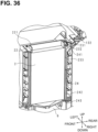
- FIG. 36 is a schematic side sectional view of an evaporative filter case 22 located in the housing 10.
- the evaporative filter water receiver 132 has a scoop shape and is disposed so as to protrude perpendicularly from the inner surface of the door 12.
- the evaporative filter water receiver 132 is disposed between the filter water supply device 21 and the support portion 115, that is, the base end portion of the evaporative filter water receiver 132 is located between the filter water supply device 21 and the support portion 115 on the inner surface of the door 12.
- the scoop-shaped evaporative filter water receiver 132 has a distal end portion located further away from the inner surface of the door 12 than the nozzles 211 of the filter water supply device 21.
- the protruding direction of the evaporative filter water receiver 132 is parallel to the orientation of the nozzles 211 of the filter water supply device 21.
- the protruding direction of the evaporative filter water receiver 132 and the orientation of the nozzles 211 of the filter water supply device 21 are directed downward.
- the protruding direction of the evaporative filter water receiver 132 and the orientation of the nozzles 211 of the filter water supply device 21 are directed forward.
- the evaporative filter water receiver 132 includes a rectangular flat plate portion and two side wall portions formed at opposite ends of the flat plate portion in the longitudinal direction, forming a scoop shape.
- the longitudinal direction of the flat plate portion of the evaporative filter water receiver 132 and the longitudinal direction of the rectangular box-shaped filter water supply device 21 intersect perpendicularly.
- the evaporative filter water receiver 132 When the door 12 is open, the evaporative filter water receiver 132 are positioned so that its longitudinal direction is vertical, and the nozzles 211 arranged in the longitudinal direction vary in height.
- the evaporative filter case 22 has, on its upper surface, a columnar rib 221 protruding upward, as in the case of the first embodiment, and a water dripping rib 231 also protruding upward.
- the water dripping rib 231 has a rectangular shape similarly to the columnar rib 221, and is located adjacent to the outer edge of the columnar rib 221.
- the water dripping rib 231 is located between the columnar rib 221 and the support portion 115.
- the upper surface of the evaporative filter case 22 has a hole inside the water dripping rib 231, and the hole corresponds to the water dripping hole 232.
- the drain pan 6 is disposed below the evaporative filter case 22, and an evaporative filter fitting member 24 is located between the evaporative filter case 22 and the drain pan 6.
- the evaporative filter case 22 When placed in the housing 10, the evaporative filter case 22 is fitted into the evaporative filter fitting member 24.
- the evaporative filter fitting member 24 may function as a structural member constituting the inner wall of the housing 10.
- the evaporative filter fitting member 24 is formed with an inclined surface that slopes downward.
- the inclined surface constitutes an evaporative filter inclined surface portion 241.
- the evaporative filter inclined surface portion 241 is located adjacent to the first side wall 111 of the housing 10 on which the support portions 115 is located. Therefore, the evaporative filter inclined surface portion 241 is located between the water dripping rib 231 and the support portion 115.
- the evaporative filter inclined surface portion 241 is inclined such that a distance between the evaporative filter inclined surface portion 241 and a side surface of the evaporative filter case 22 facing the inner surface on which the evaporative filter inclined surface portion 241 is formed decreases from the upper side to the lower side.
- the upper end of the evaporative filter inclined surface portion 241 is widened, and the upper end of the evaporative filter inclined surface portion 241 and the side surface of the evaporative filter case 22 define an insertion portion into which the distal end portion of the evaporative filter water receiver 132 is inserted.
- the length of the evaporative filter inclined surface portion 241 in the left-right direction is greater than the length of the evaporative filter water receiver 132 in the left-right direction. Further, the evaporative filter water receiver 132 is located at a position overlapping the evaporative filter inclined surface portion 241 in the left-right direction. Specifically, the left end of the evaporative filter water receiver 132 is located further to the right than the left end of the evaporative filter inclined surface portion 241, and the right end of the evaporative filter water receiver 132 is located further to the left than the right end of the evaporative filter inclined surface portion 241.
- the distal end portion of the evaporative filter water receiver 132 is located between the evaporative filter inclined surface portion 241 and the side surface of the evaporative filter case 22. That is, the distal end portion of the evaporative filter water receiver 132 is inserted into the insertion portion defined by the evaporative filter inclined surface portion 241 and the side surface of the evaporative filter case 22 facing the evaporative filter inclined surface portion 241.
- water received by the evaporative filter water receiver 132 can flow from the evaporative filter inclined surface portion 241 into a space between the evaporative filter inclined surface portion 241 and the side surface of the evaporative filter case 22, and can be guided to the bottom of the evaporative filter fitting member 24.
- the bottom of the evaporative filter fitting member 24 has a hole, which corresponds to an evaporative filter communication hole 243.
- the evaporative filter communication hole 243 communicates with the drain pan 6 located below the evaporative filter case 22. In this manner, water received by the evaporative filter water receiver 132 flows between the inner surface of the evaporative filter fitting member 24 on which the evaporative filter inclined surface portion 241 is formed and the side surface of the evaporative filter case 22 facing the inner surface.
- the inner surface of the evaporative filter fitting member 24 and the side surface of the evaporative filter case 22 define an outer drainage channel 242.
- the outer drainage channel 242 includes the evaporative filter inclined surface portion 241 and an evaporative filter communication hole 243.
- the water can be received at the evaporative filter water receiver 132. Then, when the door 12 is closed, the water received at the evaporative filter water receiver 132 can be collected in the drain pan 6 through the outer drainage channel 242 including the evaporative filter inclined surface portion 241 and the evaporative filter communication hole 243. Furthermore, by locating the water dripping rib 231 adjacent to the evaporative filter inclined surface portion 241, any water that has overflowed the evaporative filter inclined surface portion 241 can be contained within the water dripping rib 231.
- This water can then be directed into the inner drainage channel 233, inside the evaporative filter case 22, through the water dripping hole 232 formed within the water dripping rib 231. This can prevent water dripping from the nozzles 211 of the filter water supply device 21 from flowing outside the housing 10 when the door 12 is opened and closed.
- the internal diameter of the evaporative filter communication hole 243 is, for example, 3 mm ( ⁇ 3), and the hole surface of the evaporative filter communication hole 243 is set to a sufficiently small value with respect to the cross-sectional area of the path through which the supply air flows in the evaporative filter 2.
- the ventilation resistance in the outer drainage channel 242 is increased. This sufficiently reduces the possibility that the supply air bypasses the evaporative filter 2 without passing through the evaporative filter 2.
- the present embodiment shows, but is not limited to, that the heat exchanger water receiver 131 and the evaporative filter water receiver 132 have a scoop shape with a tip portion.
- the heat exchanger water receiver 131 and the evaporative filter water receiver 132 may be, for example, flexible members such as films, with one end coupled to the inner side of the door 12 and the other end coupled to the inner side of the housing 10.
- the heat exchanger water receiver 131 and the evaporative filter water receiver 132 formed of soft films, have flexibility, and can thus accommodate deformation when the door 12 is opened and closed.
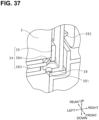
- FIG. 37 is a schematic cross-sectional side view showing a return portion 392.
- the heat exchanger fitting member 39 into which the heat exchanger case 34 is fitted has a return portion 392 that prevents the outflow of water outside the heat exchanger fitting member 39.
- the return portion 392 functions as a water collection structure.
- the return portion 392 is formed on a side plate of the heat exchanger fitting member 39 facing the supply air inlet-side frame 35 of the heat exchanger case 34, and protrudes outward from the side plate.
- the return portion 392 is located in a lower portion of the side plate and in the vicinity of the lower frame body of the supply air inlet-side frame 35.
- the return portion 392 is formed to cover part of the supply-air flow passage, through which the supply air passes, in the heat exchanger fitting member 39 from the lower side to the upper side. This can prevent water accumulating in the heat exchanger case 34 or the heat exchanger fitting member 39 from flowing outside the heat exchanger fitting member 39. Thus, for example, even when the air conditioner 1 is mounted on a moving body such as a vehicle and is inclined due to the movement of the vehicle, water can be prevented from flowing outside the housing 10.
- the air conditioner 1 includes the housing 10 that houses the cooling unit 20.
- the housing 10 includes the door 12 that can be opened and closed, and the support portions 115 that support the door 12 on the first side wall 111 of the housing 10.
- the door 12 to which the water supply device is fixed has a water receiver.
- the water receiver is located between the water supply device and the support portions 115.
- the air conditioner 1 includes the evaporative filter case 22 and the evaporative filter fitting member 24.
- the housing 10 includes the evaporative filter fitting member 24, which engages with the evaporative filter case 22 when the evaporative filter case 22 is housed in the housing 10.
- the water receiver includes the evaporative filter water receiver 132.
- the evaporative filter water receiver 132 is disposed at a position overlapping the evaporative filter fitting member 24 in a first horizontal direction that is perpendicular to the vertical direction and parallel to the first wall 341, that is, in the left-right direction.
- water received by the evaporative filter water receiver 132 can be directed into the outer drainage channel 242.
- the evaporative filter fitting member 24 has, in its bottom portion, the evaporative filter communication hole 243, which forms part of the outer drainage channel 242. This enables water that has flowed into the outer drainage channel 242 from the evaporative filter water receiver 132 to be discharged from the evaporative filter communication hole 243.
- the inner wall of the evaporative filter fitting member 24 has the evaporative filter inclined surface portion 241 that slopes downward.
- the length of the evaporative filter inclined surface portion 241 is greater than the length of the evaporative filter water receiver 132.
- the air conditioner 1 includes the heat exchanger case 34 that houses the sensible heat exchanger 3.
- the heat exchanger case 34 has the first wall 341 which faces the first side wall 111 of the housing 10 in a state of being accommodated in the housing 10.
- the first wall 341 is formed with the heat exchanger inclined surface portion 381 that is inclined from the upper end toward the bottom wall 383.
- the heat exchanger inclined surface portion 381 is located below the support portions 115 that rotatably support the door 12. When the door 12 is opened, water may drip from the nozzles 331 of the heat exchanger water supply devices 33 disposed inside the door 12.
- the heat exchanger case 34 includes the frame-shaped bottom wall 383 that is connected to the supply air inlet-side frame 35, the supply air outlet-side frame 36, the first wall 341, and the second wall 342.
- the bottom wall 383 has a hole.
- the hole of the bottom wall 383 is located in the vicinity of a connection portion with any one of the first wall 341, the second wall, the supply air inlet-side frame 35, or the supply air outlet-side frame 36. That is, at least one bottom wall 383 is located at any one of four corners or angular portions of the bottom wall 383 of the heat exchanger case 34, which has a rectangular frame shape.
- the bottom wall hole 384 is an example of the hole in the bottom wall 383.
- the hole of the bottom wall 383 is, for example, triangular in shape to match an angular portion of the bottom wall 383.
- the hole of the bottom wall 383 may be formed at each of two angular portions located at both ends of a connection portion with, for example, the supply air inlet-side frame 35.
- the hole of the bottom wall 383 is not limited to a hole in the bottom wall 383, and may be configured by, for example, a combination of an arc-shaped cutout portion at the outer edge of the bottom wall 383 and the supply air inlet-side frame 35 connected to the bottom wall 383.
- the inner surface of the first wall 341 of the heat exchanger case 34 has the heat exchanger inclined surface portion 381 inclined from the upper end toward the bottom wall 383.
- the water receiver includes the heat exchanger water receiver 131.
- the heat exchanger water receiver 131 is located at a position overlapping the evaporative filter fitting member 24 in the first horizontal direction. In the first horizontal direction, the length of the heat exchanger inclined surface portion 381 is greater than the length of the heat exchanger water receiver 131.
- the air conditioner 1 includes the heat exchanger case 34 that houses the sensible heat exchanger 3.
- the heat exchanger case 34 has the first wall 341 which faces the first side wall 111 of the housing 10 in a state of being accommodated in the housing 10.
- water received by the heat exchanger water receiver 131 can be directed into the heat exchanger drainage channel 382.
- bottom wall 383 of the heat exchanger case 34 has the hole (bottom wall hole 384) that forms part of the heat exchanger drainage channel 382, water flowing into the heat exchanger drainage channel 382 from the water receiver can be discharged from the bottom wall hole 384.
- the housing 10 includes the heat exchanger fitting member 39, which engages with the heat exchanger case 34 when the heat exchanger case 34 is housed in the housing 10.
- the heat exchanger fitting member 39 has the return portion 392 that prevents water from the heat exchanger water receiver 131 from flowing outside the heat exchanger fitting member 39. This can prevent water accumulating in the heat exchanger case 34 or the heat exchanger fitting member 39 from flowing outside the heat exchanger fitting member 39.
- the return portion 392 is formed on the side plate of the heat exchanger fitting member 39, which faces the supply air inlet-side frame 35 of the heat exchanger case 34 in the first horizontal direction. More specifically, the return portion 392 protrudes from the side plate of the heat exchanger fitting member 39 toward the upstream side in the supply air direction. This can efficiently prevent water accumulating in the heat exchanger case 34 or the heat exchanger fitting member 39 from flowing outside the housing 10 from the supply air inlet 42.
- a plurality of claims in the scope of claims may be combined with each other regardless of the form of citation.
- a claim may contain multiple dependent claims that are dependent on more than one claim.
- a multiple dependent claim may be set forth, which depends on another multiple dependent claim.
Landscapes
- Engineering & Computer Science (AREA)
- Chemical & Material Sciences (AREA)
- Combustion & Propulsion (AREA)
- Mechanical Engineering (AREA)
- General Engineering & Computer Science (AREA)
- Life Sciences & Earth Sciences (AREA)
- Sustainable Development (AREA)
- Devices For Blowing Cold Air, Devices For Blowing Warm Air, And Means For Preventing Water Condensation In Air Conditioning Units (AREA)
Abstract
Description
- The present invention relates to an air conditioner.
- A known evaporative cooling type air conditioner, which is disclosed in, for example,
Patent Literature 1, draws in air from a room, lowers the ambient temperature using the heat of evaporation of water, and blows the cooled air into the room. In the air conditioner ofPatent Literature 1, air flowing through a second flow passage passes through a plurality of tubes included in a sensible heat exchanger, and air flowing through a first flow passage passes around the plurality of tubes. As a result, heat is exchanged between the air flowing through the second flow passage and the air flowing through the first flow passage. - [Patent Literature 1]
JP 2014-092338 A - However, the air conditioner of
Patent Literature 1 does not account for the efficiency of maintenance work in view of the structural arrangement of a water supply device for supplying water and a cooling unit. - The present invention has been made in view of the above circumstances, and an object thereof is to provide an air conditioner that offers improved maintenance efficiency.
- An air conditioner according to an aspect of the present disclosure includes a cooling unit and a water supply device to supply water to a surface of the cooling unit. The water supply unit is movable between a first position in which the water supply device faces the surface of the cooling unit in a perpendicular direction orthogonal to the surface and a second position in which the water supply device is located away from the surface of the cooling unit in a plane direction orthogonal to the perpendicular direction.
- Easy access to the surface of the cooling unit that faces the water supply device enables efficient maintenance work of the air conditioner.
-
-
FIG. 1 is a schematic side sectional view illustrating an example configuration of an air conditioner according to an embodiment. -
FIG. 2 is a perspective external view of the air conditioner from its front. -
FIG. 3 is a perspective external view of the air conditioner from its rear. -
FIG. 4 is a perspective external view of the air conditioner from its bottom. -
FIG. 5 is a perspective external view of the air conditioner from its front with a water tank removed. -
FIG. 6 is a perspective external view of the water tank. -
FIG. 7 is a side sectional view of the water tank. -
FIG. 8 is a side cross-sectional view of the air conditioner with the water tank attached. -
FIG. 9 illustrates the air conditioner with a door opened to expose an upper surface of a cooling unit. -
FIG. 10 illustrates the air conditioner from which the cooling unit is removed. -
FIG. 11 illustrates water supply devices in a state where the door is closed. -
FIG. 12 illustrates a length relationship between a connection supply water channel and the door. -
FIG. 13 illustrates a connection structure between the water supply devices and a supply water channel. -
FIG. 14 illustrates displacement of the connection supply water channel when the door is opened and closed. -
FIG. 15 is a perspective external view of a heat exchanger case. -
FIG. 16 is an exploded perspective view of the heat exchanger case. -
FIG. 17 illustrates the heat exchanger case inserted into the housing. -
FIG. 18 is a perspective external view of an evaporative filter case with a handle raised. -
FIG. 19 is a perspective external view of the evaporative filter case with the handle lowered. -
FIG. 20 is an exploded perspective view of the evaporative filter case. -
FIG. 21 illustrates a first intermediate supply-air flow passage located between the heat exchanger case and the evaporative filter case. -
FIG. 22 is a partially enlarged view of the first intermediate supply-air flow passage. -
FIG. 23 is a schematic side sectional view of a drain pan in the housing. -
FIG. 24 illustrates a positional relationship between a bottom hole of the drain pan and a water supply hole. -
FIG. 25 illustrates the left side of the water level sensor mounted by the sensor fixing member. -
FIG. 26 illustrates the right side of the water level sensor mounted by the sensor fixing member. -
FIG. 27 illustrates how a drain pan filter is attached. -
FIG. 28 illustrates how the drain pan filter is detached. -
FIG. 29 is a block diagram illustrating functional components in the air conditioner. -
FIG. 30 illustrates an exposed upper surface of a cooling unit with a door open, according to a second embodiment. -
FIG. 31 illustrates the air conditioner from which the cooling unit is removed. -
FIG. 32 is a schematic side sectional view of a heat exchanger case located in a housing. -
FIG. 33 is an enlarged view of a part of the heat exchanger case. -
FIG. 34 is a plan view of the heat exchanger case housing the sensible heat exchanger. -
FIG. 35 is a plan view of the heat exchanger case without the sensible heat exchanger. -
FIG. 36 is a schematic side sectional view of an evaporative filter case located in the housing. -
FIG. 37 is a schematic cross-sectional side view showing a return portion. - An
air conditioner 1 according to an embodiment of the present disclosure will be described with reference to the drawings. The present disclosure is not limited to the following examples, and includes meanings equivalent to the scope of the claims and all modifications within the scope of the claims. - Hereinafter, an embodiment will be described with reference to the drawings.
FIG. 1 is a schematic side sectional view illustrating an example configuration of theair conditioner 1 according to an embodiment.FIG. 2 is a perspective external view of theair conditioner 1 from its front.FIG. 3 is a perspective external view of theair conditioner 1 from its rear.FIG. 4 is a perspective external view of theair conditioner 1 from its bottom.FIG. 1 schematically shows a cross-section of theair conditioner 1 as viewed from the front. InFIG. 1 , directional terms, up, down, left, and right, are shown based on theair conditioner 1 placed in a normal usage mode. InFigs. 2 ,3 , and4 , directional terms, up, down, front, rear, left, and right, are shown based on theair conditioner 1 placed in the normal usage mode. In the present embodiment, the vertical direction indicates the up-down direction. A first horizontal direction indicates the left-right direction. A second horizontal direction indicates the front-rear direction. - The
air conditioner 1 is mounted on a vehicle, for example, a commercial vehicle such as a forklift or a truck, a towing vehicle, a lifting vehicle, a mini excavator car, or a golf cart. When theair conditioner 1 is mounted on a mobile body such as a forklift, the power of a main body of theair conditioner 1 may be turned on and off in conjunction with a key switch of an engine of the forklift. That is, the power of theair conditioner 1 may be turned on by turning on the engine of the forklift, and the power of theair conditioner 1 may be turned off by turning off the engine of the forklift. - A
housing 10 is made of resin or metal and shaped like a rectangular box, and includes amain body 11 and adoor 12 that is openable and closable relative to themain body 11. Thehousing 10 forming a box has an upper surface, a lower surface, and side walls. The side walls include afirst side wall 111, asecond side wall 112, athird side wall 113, and afourth side wall 114. In the present embodiment, thefirst side wall 111 corresponds to a rear side wall. Thesecond side wall 112 corresponds to a front side wall. Thethird side wall 113 corresponds to a right side wall. Thefourth side wall 114 corresponds to a left side wall. Thus, thefirst side wall 111 and thesecond side wall 112 face each other. Thethird side wall 113 and thefourth side wall 114 face each other. Thethird side wall 113 connects thefirst side wall 111 and thesecond side wall 112. Thefourth side wall 114 connects thefirst side wall 111 and thesecond side wall 112. Thefirst side wall 111 is constituted by a body-sidefirst side wall 1111 and a door-sidefirst side wall 1112. - The
door 12 is disposed above themain body 11 and is openable and closable relative to themain body 11. Specifically, the door-sidefirst side wall 1112 is connected to the body-sidefirst side wall 1111 by twosupport portions 115. As thesupport portions 115, for example, hinges can be used. - The
third side wall 113 and thefourth side wall 114 of thehousing 10 have recessedhandholds 118, which extend from their respective lower portion to a lower surface. Thehandholds 118 are portions to be gripped by the user when carrying theair conditioner 1. - A
duct 431 for blowing out supply air is disposed in an upper surface of thehousing 10. Awater tank 8 is disposed beside thesecond side wall 112 of thehousing 10. Atank base 116 for arranging thewater tank 8 is positioned below thesecond side wall 112 of thehousing 10. Thewater tank 8 is disposed on thetank base portion 116, thereby covering thesecond side wall 112. Adrainage channel 781 for draining water from adrain pan 6, which will be described later, is provided in a lower portion of thetank base 116. Thewater tank 8 is detachably fitted to thehousing 10. Thewater tank 8 has a gripping portion and can be removed from thehousing 10. When refilling thewater tank 8, the user of theair conditioner 1 can bring only thewater tank 8 to a tap, thereby reducing the workload involved in refilling with water. Thewater tank 8 has a waterlevel confirmation window 82 in a side surface thereof. The user can visually recognize the amount of water remaining in thewater tank 8 through the waterlevel confirmation window 82. - The
housing 10 has asupply air inlet 42 for drawing in air in the space to be air-conditioned, and anexhaust air inlet 52. Further, thehousing 10 has asupply air outlet 43 and anexhaust air outlet 53. Thesupply air inlet 42 is defined in thethird side wall 113 of thehousing 10. Theexhaust air inlet 52 is defined in thedoor 12 forming a part of thehousing 10. Thesupply air outlet 43 is defined in the upper surface of thehousing 10 and communicates with theduct 431. Theduct 431 is rotatable in a circumferential direction of thesupply air outlet 43 and includes a winddirection adjusting plate 432 that adjusts the wind direction of the supply air blown out from theduct 431. Theexhaust air outlet 53 is defined in thefourth side wall 114 of thehousing 10. - The
air conditioner 1 includes thewater tank 8 for storing water, and a cooling unit 20 including anevaporative filter 2 and asensible heat exchanger 3, which are to be supplied with water from thewater tank 8. Theevaporative filter 2 is housed in anevaporative filter case 22. Thesensible heat exchanger 3 is housed in aheat exchanger case 34. Details of theevaporative filter case 22 and theheat exchanger case 34 will be described later. Theevaporative filter 2 lowers the ambient temperature using the heat of evaporation of the water supplied from thewater tank 8, and cools the space to be air-conditioned. Thesensible heat exchanger 3 lowers the ambient temperature using the sensible heat and the latent heat of the water supplied from thewater tank 8, and cools the space to be air-conditioned. Thesensible heat exchanger 3 is an example of a heat exchanger. Theevaporative filter 2 is disposed downstream of thesensible heat exchanger 3 in a flow direction of the supply air. That is, theevaporative filter 2 is disposed between thesensible heat exchanger 3 and thesupply air outlet 43. - Air that has passed through the
sensible heat exchanger 3 and theevaporative filter 2 undergoes two-stage cooling processes. The air is cooled by thesensible heat exchanger 3 and theevaporative filter 2, and is blown out through thesupply air outlet 43 into the space to be air-conditioned as supply air. Further, when the air passes through thesensible heat exchanger 3, the air is cooled by the water supplied to thesensible heat exchanger 3, and then the air that has undergone sensible heat exchange with the supply air in thesensible heat exchanger 3 is blown outside theair conditioner 1 through theexhaust air outlet 53 as exhaust air. - The
supply air inlet 42 and thesupply air outlet 43 communicate with each other. Thesupply air inlet 42 as an inlet for supply air and thesupply air outlet 43 as an outlet for supply air define a supply-air flow passage 4 through which air that will be supply air flows. - That is, supply air flows into the supply-
air flow passage 4 through thesupply air inlet 42 and flows out through thesupply air outlet 43. Thesupply air inlet 42 may be covered with a supply air dust collecting filter for collecting dust in the supply air drawn in through thesupply air inlet 42. - The
exhaust air inlet 52 and theexhaust air outlet 53 communicate with each other. Theexhaust air inlet 52 as an inlet for exhaust air and theexhaust air outlet 53 as an outlet for exhaust air define an exhaust-air flow passage 5 through which air that will be exhaust air flows. - That is, exhaust air flows into the exhaust-
air flow passage 5 through theexhaust air inlet 52 and flows out through theexhaust air outlet 53. Theexhaust air inlet 52 may be covered with an exhaust air dust collecting filter for collecting dust in the exhaust air drawn in through theexhaust air inlet 52. - The
air conditioner 1 includes fans for conveying supply air and exhaust air. The fans includes asupply fan 41 for conveying supply air, and anexhaust air fan 51 for conveying exhaust air. Thesupply fan 41 and theexhaust air fan 51 may be, for example, axial flow fans such as propeller fans or sirocco fans. Thesupply fan 41 is disposed in the vicinity of thesupply air outlet 43 and downstream of the cooling unit 20 in the flow direction of the supply air in the supply-air flow passage 4, and functions as a suction fan. - The
exhaust air fan 51 is disposed in the vicinity ofexhaust air outlet 53 and downstream of thesensible heat exchanger 3 in a flow direction in which exhaust air flows in exhaust-air flow passage 5, and functions as a suction fan. Thesupply fan 41 and theexhaust air fan 51 are not limited to these aspects, and both may be either a push-out fan or a suction fan. When thesupply air fan 41 and theexhaust air fan 51 are push-out fans, thesupply fan 41 is disposed in the vicinity of thesupply air inlet 42, and theexhaust air fan 51 is disposed in the vicinity of theexhaust air inlet 52. - The exhaust air conveyed by the
exhaust air fan 51 is drawn in through theexhaust air inlet 52 and flows into anexhaust air channel 32 of thesensible heat exchanger 3. Since theexhaust air inlet 52 is defined in thedoor 12, the exhaust air drawn in through theexhaust air inlet 52 passes through thedoor 12 and then flows into theexhaust air channel 32 of thesensible heat exchanger 3. - The
sensible heat exchanger 3 includes asupply air channel 31, through which supply air flows, and anexhaust air channel 32, through which exhaust air flows. That is, thesensible heat exchanger 3 includes thesupply air channel 31 and theexhaust air channel 32. As described above, theair conditioner 1 includes the supply-air flow passage 4, through which supply air flows, and the exhaust-air flow passage 5, through which exhaust air flows, as air flow passages. Thesupply air channel 31 of thesensible heat exchanger 3 forms a part of the supply-air flow passage 4, and theexhaust air channel 32 of thesensible heat exchanger 3 forms a part of the exhaust-air flow passage 5. - The
supply air channel 31 and theexhaust air channel 32 in thesensible heat exchanger 3 are defined by a plurality of resin plates, such as corrugated plastic, each having a hollow structure, and these plates stacked in parallel constitute thesensible heat exchanger 3. Using thin resin plates in thesensible heat exchanger 3 improves heat transfer performance and reduces its weight. The hollow structure may be constituted by metal plates. - The resin plates are stacked such that the
supply air channel 31 and theexhaust air channel 32 are provided perpendicularly to each other, and sensible heat exchange between supply air and exhaust air is performed via the resin plates. - The stacking direction of the stacked resin plates is perpendicular to an extending direction of each of the
supply air channel 31 and theexhaust air channel 32. That is, in the present embodiment, the extending direction of thesupply air channel 31 is from right to left, and the extending direction of theexhaust air channel 32 is from top to bottom, whereas the stacking direction is the front-rear direction perpendicular to both the left-right direction and the up-down direction. Since thesupply air channel 31 and theexhaust air channel 32 are orthogonal to each other as described above, supply air flowing through thesupply air channel 31 and exhaust air flowing through theexhaust air channel 32 form crossflow. - Two opposite side surfaces of the
sensible heat exchanger 3 has an inlet and an outlet of thesupply air channel 31, respectively. In the illustration of the present embodiment, the inlet of thesupply air channel 31 is located in the right surface of thesensible heat exchanger 3, and the outlet of thesupply air channel 31 is located in the left surface of thesensible heat exchanger 3. - The
supply air channel 31 is defined by stacked spaces communicating with each other from the inlet of thesupply air channel 31 toward the outlet of thesupply air channel 31. Thesensible heat exchanger 3 has an inlet of theexhaust air channel 32 in its upper surface, and an outlet of theexhaust air channel 32 in its lower surface. Theexhaust air channel 32 is defined by stacked spaces each extending from the inlet of theexhaust air channel 32 toward the outlet of theexhaust air channel 32. - A box-shaped
drain pan 6 having an opening at the top is disposed below the cooling unit 20, that is, theevaporative filter 2 and thesensible heat exchanger 3. Thedrain pan 6 receives water that has been supplied from a heat exchangerwater supply device 33 to be described later and has passed through thesensible heat exchanger 3. Thedrain pan 6 further receives water that has supplied from a filterwater supply device 21 to be described later and has passed through theevaporative filter 2. Thedrain pan 6 is disposed downstream of thesensible heat exchanger 3 in the flow direction of the exhaust air with its opening facing the lower surfaces of theevaporative filter 2 and thesensible heat exchanger 3. That is, a water storage space that is an internal space of thedrain pan 6 forms a part of the exhaust-air flow passage 5. - The exhaust air, which has been drawn in through the
exhaust air inlet 52 by theexhaust air fan 51 and has passed through theexhaust air channel 32 of thesensible heat exchanger 3, passes through the water storage space of thedrain pan 6 having a box shape with an open upper surface, and is blown out through theexhaust air outlet 53. Upon passing through theexhaust air channel 32 of thesensible heat exchanger 3, the exhaust air mixes with water supplied to theexhaust air channel 32 from the heat exchangerwater supply device 33. That is, in theexhaust air channel 32 of thesensible heat exchanger 3, the flow direction of the exhaust air and the flow direction of the water are the same direction, and the exhaust air and the water form a parallel flow. - In the example of the present embodiment shown in
FIG. 1 , thesupply air channel 31 through which the supply air flows is provided linearly from the right surface toward the left surface of thesensible heat exchanger 3. Theevaporative filter 2 is disposed downstream of the outlet from thesupply air channel 31 in the flow direction of the supply air. Theevaporative filter 2 is disposed on the supply-air flow passage 4 between thesensible heat exchanger 3 and thesupply air outlet 43. A first intermediate supply-air flow passage 44 is located between thesensible heat exchanger 3 and theevaporative filter 2, and the first intermediate supply-air flow passage 44 forms a part of the supply-air flow passage 4. - The
evaporative filter 2 is disposed such that one rectangular surface thereof faces the left surface of thesensible heat exchanger 3 in which the outlet from thesupply air channel 31 is formed. Theevaporative filter 2 thus functions as a cooling element. Theevaporative filter 2 is formed of, for example, rayon polyester or non-woven fabric. A filterwater supply device 21 havingnozzles 211 is disposed above theevaporative filter 2. Details of the filterwater supply device 21 will be described later. Theevaporative filter 2 has water absorbency, and water supplied from the filterwater supply device 21 permeates the entire surface of theevaporative filter 2, thereby promoting the evaporation of water. The supply-air flow passage 4 extends from the supply-airevaporative filter 2 upward to thesupply air outlet 43. - The supply air flowing out through the
supply air channel 31 of thesensible heat exchanger 3 passes through theevaporative filter 2 and is blown out through thesupply air outlet 43 to the space to be air-conditioned. The supply air flowing out from the outlet from thesupply air channel 31 is primarily cooled by the exhaust air through thesensible heat exchanger 3, and is secondarily cooled through the supply-airevaporative filter 2, whereby the supply air is cooled in two stages. Therefore, the temperature of the supply air is further lowered as compared with a direct evaporation method that uses, for example, only theevaporative filter 2. - The residual water of the
sensible heat exchanger 3 and theevaporative filter 2 unit are received by thedrain pan 6 located below thesensible heat exchanger 3 and theevaporative filter 2, and the residual water is collected by being stored in the water storage space of thedrain pan 6. The water collected in thedrain pan 6 is supplied to theevaporative filter 2 unit and thesensible heat exchanger 3 via asupply water channel 7. - As shown in
FIG. 1 , adrain pan filter 75, aflow rate sensor 77, and awater supply pump 76 are disposed in thesupply water channel 7. The water stored in thedrain pan 6 by driving thewater supply pump 76 is supplied to each of the filterwater supply device 21 disposed above theevaporative filter 2 and the heat exchangerwater supply device 33 disposed above thesensible heat exchanger 3 by thewater supply pump 76. The water dripping from thenozzles 211 of the filterwater supply device 21 is supplied to theevaporative filter 2. The water dripping from thenozzles 331 of the heat exchangerwater supply device 33 is supplied to theexhaust air channel 32 of thesensible heat exchanger 3. In this manner, thesupply water channel 7, the heat exchangerwater supply device 33, the filterwater supply device 21, and thedrain pan 6 form a circulation water channel for circulating water between thedrain pan 6, and theevaporative filter 2 and thesensible heat exchanger 3, which constitute the cooling unit 20. - The
supply water channel 7 communicates with abottom hole 611 in thebottom surface 61 of thedrain pan 6. Thesupply water channel 7 includes a firstsupply water channel 71 extending upward from below along thefirst side wall 111 of thehousing 10, a secondsupply water channel 72 connected to the heat exchangerwater supply device 33, a connectingsupply water channel 73 connecting the firstsupply water channel 71 and the secondsupply water channel 72, and a water supplydevice connection channel 74 connecting the heat exchangerwater supply device 33 and the filterwater supply device 21. The heat exchangerwater supply devices 33, the filterwater supply device 21, the water supplydevice connection channel 74, and the secondsupply water channel 72 are fixed to thedoor 12. The firstsupply water channel 71, the secondsupply water channel 72, and the water supplydevice connection channel 74 are constructed from, for example, resin or metal pipes. Details of the heat exchangerwater supply device 33, the filterwater supply device 21, and the connectingsupply water channel 73 that are fixed to thedoor 12 will be described later. - The
supply water channel 7 has abranch portion 78 that branches into thedrainage channel 781. Thedrainage channel 781 has thebranch portion 78 at its base end, and a drain outlet having an on-off valve or a cock at its distal end. - The
drainage channel 781 is constructed from, for example, a resin pipe. The on-off valve in the drain outlet located at the distal end of thedrainage channel 781 is fully closed during normal use, such as when theair conditioner 1 is operated. At the time of maintenance work such as maintenance of theair conditioner 1, water stored in thedrain pan 6 can be discharged through the drain outlet outside of theair conditioner 1 by opening the on-off valve. - The
drain pan 6 and thewater tank 8 are communicated with each other by a replenishingwater channel 9. The replenishingwater channel 9 is constructed from, for example, a resin or metal pipe. The replenishingwater channel 9 includes atank pump 91 and a tankflow rate sensor 92. The replenishingwater channel 9 has one end connected to a lower portion of thewater tank 8, and the other end connected to awater supply hole 621 in awall surface 62 of thedrain pan 6. Thewater supply hole 621 is located above thebottom hole 611 to which thesupply water channel 7 is connected. Awater level sensor 63 is fixed above thebottom surface 61 of thedrain pan 6 by asensor fixing member 64. Thewater level sensor 63 is fixed at a position offset from a perpendicular line to the cross section of thewater supply hole 621. In other words, thewater level sensor 63 is disposed at a position away from thewater supply hole 621 in the up-down direction and the left-right direction. -
FIG. 5 is a perspective external view of theair conditioner 1 from its front with thewater tank 8 removed. Thehousing 10 has atank base 116 for positioning thewater tank 8, adjacent to thesecond side wall 112. Thetank base 116 extends forward beyond thesecond side wall 112, creating a step between thetank base 116 and thesecond side wall 112. Thetank base 116 hascylindrical bosses 117 on its upper surface. In the present embodiment, twobosses 117 are disposed on the upper surface of thetank base 116. A communication hole, which communicates with the replenishingwater channel 9, is located between the twobosses 117. As described above, when thewater tank 8 is disposed on the upper surface of thetank base 116, thebosses 117 are engaged in the recessedboss receiving portions 81 formed on the lower surface of thewater tank 8. - A
lock mechanism 14 for maintaining thedoor 12 in a closed state is disposed on thesecond side wall 112 of thehousing 10. Thelock mechanism 14 includes lock hooks 142, engagement holes 143 in which the lock hooks 142 are engaged, a spring that biases the lock hooks 142 in a certain direction, and anoperation portion 141 for moving the lock hooks 142 in a direction against the biasing force of the spring. More specifically, the lock hooks 142, the spring, and theoperation portion 141 of thelock mechanism 14 are provided on the front wall of thedoor 12 constituting a part of thesecond side wall 112, and the engagement holes 143 in which the lock hooks 142 are engaged is provided on the front wall of themain body 11 forming a part of thesecond side wall 112. The outer surface of thelock mechanism 14 is configured to be flush with thesecond side wall 112, that is, the outer surface of thelock mechanism 14 forms a part of thesecond side wall 112. Theoperation portion 141 is disposed inside a recessed portion formed on the outer surface of thelock mechanism 14, and is constituted by a lever used for opening and closing thedoor 12. - When the
water tank 8 is attached to thehousing 10, thewater tank 8 is placed on the upper surface of thetank base 116. At this time, the rear surface of thewater tank 8 faces thesecond side wall 112 of thehousing 10. That is, when thewater tank 8 is attached to thehousing 10, the outer surface of thelock mechanism 14 faces the rear surface of thewater tank 8. In other words, thelock mechanism 14 is formed at a position to overlap thewater tank 8 in the up-down direction and the left-right direction. As a result, thelock mechanism 14 located on thesecond side wall 112 is covered by the rear surface of thewater tank 8. Thus, when thewater tank 8 is attached to thehousing 10, the operator of theair conditioner 1 is prevented from using theoperation portion 141 to open thedoor 12. -
FIG. 6 is a perspective external view of thewater tank 8.FIG. 7 is a side sectional view of thewater tank 8. Thewater tank 8 is made of, for example, resin or metal, and has a rectangular box shape. Thewater tank 8 has, on its lower surface, theboss receiving portions 81 corresponding to thebosses 117 of thetank base 116. - When the
bosses 117 are formed in a convex shape as in the present embodiment, theboss receiving portions 81 are formed in a concave shape, so that thebosses 117 and theboss receiving portions 81 are engaged with each other. - The lower surface of the
water tank 8 has acylindrical outflow portion 83 protruding between the twoboss receiving portions 81. Thecylindrical outflow portion 83 has an internal space that functions as an outflow hole through which the water in thewater tank 8 flows out. The water in thewater tank 8 flows through thecylindrical outflow portion 83 into the replenishingwater channel 9. Thecylindrical outflow portion 83 may have a valve body for stopping the outflow of water from thewater tank 8 when thewater tank 8 is removed. - The
water tank 8 has, on its upper surface, an inflow hole used for adding water in thewater tank 8. -
FIG. 8 is a side cross-sectional view of theair conditioner 1 with thewater tank 8 attached. This side cross-sectional view shows thehousing 10 as viewed from thethird side wall 113. Thewater tank 8 and thewater supply pump 76 for supplying water from thewater tank 8 to thedrain pan 6 are positioned differently from thesensible heat exchanger 3 and thedrain pan 6 in the vertical direction and a direction perpendicular to a direction from the entrance to thesupply air channel 31 in thesensible heat exchanger 3 toward the outlet therefrom. That is, in a side view based on a plane defined by the extending direction of thesupply air channel 31 of thesensible heat exchanger 3 and the vertical direction, thewater tank 8 and thewater supply pump 76 located below thewater tank 8 are located at different positions from thesensible heat exchanger 3 and thedrain pan 6, which are arranged vertically. -
FIG. 9 is an explanatory view of the air conditioner with the upper surface of the cooling unit 20 exposed by opening thedoor 12.FIG. 10 illustrates the air conditioner from which the cooling unit 20 is removed.FIG. 11 illustrates water supply devices in a state where thedoor 12 is closed. Thehousing 10 has thedoor 12 configured to be freely opened and closed. That is, thedoor 12 forms a part of thehousing 10, and the upper surface of thedoor 12 forms a part of the upper surface of thehousing 10. A front wall of thedoor 12 forms a part of thesecond side wall 112 of thehousing 10, and includes a part of alock mechanism 14 for fixing thedoor 12 to themain body 11 in a closed state. When theoperation portion 141 is operated, thelock mechanism 14 is released, and thedoor 12 rotates about thesupport portions 115 disposed on thefirst side wall 111 to be in an open state. - The
door 12 has a box shape, and the filterwater supply device 21 and the heat exchangerwater supply device 33 are disposed inside thedoor 12. The filterwater supply device 21 and the heat exchangerwater supply device 33 are fixed to the inside of the box-shapeddoor 12. Therefore, the filterwater supply device 21 and the heat exchangerwater supply device 33 change their positions or orientations relative to the cooling unit 20 in conjunction with opening or closing of thedoor 12. The filterwater supply device 21 and the heat exchangerwater supply device 33 are each an example of a water supply device. - When the
door 12 is closed, the filterwater supply device 21 and the heat exchangerwater supply device 33 are in a first position in which they face the upper surface of the cooling unit 20, in a perpendicular direction to the upper surface. When thedoor 12 is open, the filter water supply device 21and the heat exchangerwater supply device 33 are in a second position in which they are located away from the upper surface in a plane direction orthogonal to the perpendicular direction to the upper surface of the cooling unit 20. The filterwater supply device 21 and the heat exchangerwater supply device 33 that are fixed to thedoor 12 can be moved between the first position and the second position in conjunction with opening or closing of thedoor 12. - The present embodiment shows, but is not limited to, that the filter
water supply device 21 and the heat exchangerwater supply device 33 are fixed to thedoor 12. The filterwater supply device 21 and the heat exchangerwater supply device 33 may not be fixed to thedoor 12, but may be disposed on an inner lid located between thedoor 12 and themain body 11. The filterwater supply device 21 and the heat exchangerwater supply device 33 configured as part of the inner lid can be in a first position or a second position according to the opened or closed state of the inner lid. - The filter
water supply device 21 and the heat exchangerwater supply device 33 fixed to thedoor 12 are connected by the water supplydevice connection channel 74. In the present embodiment, two heat exchangerwater supply devices 33 are disposed, and the downstream heat exchangerwater supply device 33 in the flow direction of water in thesupply water channel 7 and the filterwater supply device 21 are connected by the water supplydevice connection channel 74. These two heat exchangerwater supply devices 33 are connected by the secondsupply water channel 72, and the secondsupply water channel 72 is bent in an L shape and connected to one end of the connectingsupply water channel 73. The other end of the connectingsupply water channel 73 is connected to the firstsupply water channel 71 disposed along thefirst side wall 111 of thehousing 10, more specifically, the body-sidefirst side wall 1111. As will be described in detail later, the connectingsupply water channel 73 is flexible and relieves or absorbs stress generated when thedoor 12 is opened and closed. - As shown in
FIG. 9 , the heat exchangerwater supply devices 33 are constructed from, for example, rectangular parallelepiped hollow pipes made of resin or metal, and have a plurality ofnozzles 331 withholes 332 formed in their lower surfaces, which face thesensible heat exchanger 3. The secondsupply water channel 72 passes over the heat exchangerwater supply devices 33 and is connected to communication ports provided in upper portions of the heat exchangerwater supply devices 33. The water flowing into the secondsupply water channel 72 from the connectingsupply water channel 73 is supplied to the heat exchangerwater supply devices 33 via the communication ports provided in the upper portions of the heat exchangerwater supply devices 33. Then, the water supplied to the heat exchangerwater supply devices 33 falls in drops onto the upper surface of thesensible heat exchanger 3 from theholes 332 of the plurality of nozzles 331located in the lower surfaces. The upper surface of thesensible heat exchanger 3 forms a part of the upper surface of the cooling unit 20. - The filter
water supply device 21 is constructed from, for example, a rectangular parallelepiped hollow pipe made of resin or metal, and has a plurality ofnozzles 211 withholes 212 formed in a lower surface, which faces theevaporative filter 2. Further, the filterwater supply device 21 has a hole in its right surface, that is, adjacent to the side surface of the heat exchangerwater supply device 33. The filterwater supply device 21 is positioned, in the up-down direction, at the same height as the water supplydevice connection channel 74, which is connected to the communication port in the side surface of the filterwater supply device 21. Water flowing from the secondsupply water channel 72 into the water supplydevice connection channel 74 is supplied to the filterwater supply device 21 via the communication port in the side surface of the filterwater supply device 21. Then, the water supplied to the filterwater supply device 21 falls in drops onto the upper surface of theevaporative filter 2 from theholes 212 of the plurality ofnozzles 211 in the lower surface. The upper surface of theevaporative filter 2 forms the other part of the upper surface of the cooling unit 20. In other words, the upper surface of thesensible heat exchanger 3 and the upper surface of theevaporative filter 2 constitute the upper surface of the cooling unit 20. The upper surface of the cooling unit 20 is an example of a surface of the cooling unit. - The filter
water supply device 21 and the heat exchangerwater supply device 33 are connected in series by the water supplydevice connection channel 74, and the water supplydevice connection channel 74 may have anorifice 741 to be described later. Thus, the volumetric flow rate by the filterwater supply device 21 can be reduced compared to the volumetric flow rate by the heat exchangerwater supply device 33. The flow rate adjustment in the filterwater supply device 21 and the heat exchangerwater supply device 33 is not limited to using theorifice 741 of the water supplydevice connection channel 74. Instead, the flow rate can also be adjusted by making the hole diameter of thenozzles 211 of the filterwater supply device 21 smaller than the hole diameter of the nozzle of the heat exchangerwater supply device 33. - With such a connection form, the second
supply water channel 72, the heat exchangerwater supply devices 33, the water supplydevice connection channel 74, and the filterwater supply device 21 are arranged in this order in the flow direction of supply water inside the box-shapeddoor 12. The internal space of the box-shapeddoor 12 is divided into a region in which the filterwater supply device 21 is disposed and a region in which the heat exchangerwater supply devices 33 are disposed. The region in which the heat exchangerwater supply devices 33 are disposed communicates with theexhaust air inlet 52 formed in the upper surface of thedoor 12, thereby forming a part of the exhaust-air flow passage 5. That is, the exhaust sucked air drawn in from theexhaust air inlet 52 passes through the region where the heat exchangerwater supply devices 33 are disposed inside thedoor 12, and then flows into theexhaust air channel 32 of thesensible heat exchanger 3. The heat exchangerwater supply devices 33, when fixed to thedoor 12, may be held by, for example, a rectangular tubular frame body. In this case, the inside of the frame body that holds the heat exchangerwater supply devices 33 forms a part of the exhaust-air flow passage 5. The water supplydevice connection channel 74 for connecting the heat exchangerwater supply device 33 and the filterwater supply device 21 is arranged by passing through a through-hole in the frame body. - Since the region where the filter
water supply device 21 is disposed is separate from the exhaust-air flow passage 5 located inside thedoor 12, the exhaust air drawn in from theexhaust air inlet 52 formed in thedoor 12 does not flow into the region. That is, when thehousing 10 is viewed in a plan view from above, theexhaust air inlet 52 formed in thedoor 12 is disposed at a position shifted from the filterwater supply device 21 and overlapping the heat exchangerwater supply devices 33. - The filter
water supply device 21 is fixed to thedoor 12 by a fixingmember 122 to which asecond sealing member 123 is attached. When thedoor 12 is closed, thesecond sealing member 123 comes into contact with the upper end of acolumnar rib 221 of theevaporative filter case 22, thereby ensuring the sealing property in the supply-air flow passage 4. Details of theevaporative filter case 22 and other elements will be described later. - The
door 12 is formed withaccommodation spaces 121 in which handles 37 of theheat exchanger case 34 described later are accommodated. Theaccommodation spaces 121 are located to correspond with the positions of thehandles 37 of theheat exchanger case 34 when thedoor 12 is closed, and are recessed inside thedoor 12. When thedoor 12 is closed, thehandles 37 of theheat exchanger case 34 are fitted into theaccommodation spaces 121. Thehandles 37 can be thus disposed so as not to interfere with the filterwater supply device 21, the heat exchangerwater supply devices 33, and the water supplydevice connection channel 74. In this manner, thehandles 37 disposed on a supply air inlet-side frame 35 and a supply air outlet-side frame 36 of theheat exchanger case 34 are positioned outside the wall body constituting the exhaust-air flow passage 5 inside thedoor 12, and the ventilation resistance in the exhaust-air flow passage 5 can be reduced. Regarding the positional relationship between thehandles 37 and the connectingsupply water channel 73, the connectingsupply water channel 73 is orthogonal to the vertical direction and is located offset from thehandles 37 in a second horizontal direction directed from thefirst side wall 111 to thesecond side wall 112. - The filter
water supply device 21 and the heat exchangerwater supply devices 33 are fixed to thedoor 12 configured to be openable and closable as described above. When thedoor 12 is closed, the filterwater supply device 21 and the heat exchangerwater supply devices 33 can be positioned above theevaporative filter 2 and thesensible heat exchanger 3 to be in the first position in which water can fall in drops. Further, by opening thedoor 12, the filterwater supply device 21 and the heat exchangerwater supply devices 33 can be moved into the second position in which the upper surfaces of theevaporative filter 2 and thesensible heat exchanger 3 are exposed. As described above, theevaporative filter 2 is accommodated in theevaporative filter case 22, and thesensible heat exchanger 3 is accommodated in theheat exchanger case 34, and these two components are disposed in thehousing 10. By opening thedoor 12, the filterwater supply device 21 and the heat exchangerwater supply devices 33 positioned above the cooling unit 20 during operation of theair conditioner 1 are moved to a position different from the cooling unit 20 in a plan view when theair conditioner 1 is viewed from above. Thus, theevaporative filter case 22 and theheat exchanger case 34 can be pulled out upward and removed from thehousing 10, and maintenance work such as cleaning or replacement of theevaporative filter 2 and thesensible heat exchanger 3 can be performed efficiently. -
FIG. 12 is an explanatory view showing a length relationship between the connectingsupply water channel 73 and thedoor 12.FIG. 13 illustrates a connection structure between the water supply devices and thesupply water channel 7. The connectingsupply water channel 73, which connects the firstsupply water channel 71 disposed along thefirst side wall 111 of thehousing 10, and the secondsupply water channel 72, which is connected to the heat exchangerwater supply devices 33 fixed to thedoor 12, has flexibility, and is constructed from, for example, a highly flexible resin pipe or rubber hose. - The downstream heat exchanger
water supply device 33 and the filterwater supply device 21 are connected by the water supplydevice connection channel 74 having anorifice 741. The heat exchangerwater supply devices 33 have nozzles at their distal ends, and a perpendicular line to a cross section of a hole of each nozzle is parallel to theexhaust air channel 32. Thus, a water discharge direction in which water is discharged from the nozzles of the heat exchangerwater supply devices 33 is a direction along theexhaust air channel 32 in the heat exchangerwater supply devices 33 and is perpendicular, that is, orthogonal, to thesupply air channel 31. The filterwater supply device 21 has nozzles at its distal end, and a perpendicular line to a cross section of a hole of each nozzle is parallel to theexhaust air channel 32. Thus, a direction in which water is discharged from thenozzles 211 of the filterwater supply device 21 is perpendicular to the flow direction of the supply air in theevaporative filter 2. In the present embodiment, the flow direction of the exhaust air in theexhaust air channel 32 is parallel to the water discharge direction in which water is discharged from each nozzle. - The connecting
supply water channel 73 is connected at one end to the firstsupply water channel 71 and at the other end to the secondsupply water channel 72. The firstsupply water channel 71 and the connectingsupply water channel 73 are connected by afirst connection portion 731 that is located at a position closer to thethird side wall 113 than to thefourth side wall 114. Thefirst connection portion 731 is constructed from a connecting component such as an L-shaped elbow. The secondsupply water channel 72 and the connectingsupply water channel 73 are connected by asecond connection portion 732 that is disposed at a position closer to thefourth side wall 114 than to thethird side wall 113. Thesecond connection portion 732 is constructed from a connecting component such as an L-shaped elbow. The connectingsupply water channel 73 can be arranged along the longitudinal direction of thefirst side wall 111, that is, a first horizontal direction directed from thethird side wall 113 toward thefourth side wall 114, and the connectingsupply water channel 73 can be made relatively long. Furthermore, the connectingsupply water channel 73 is orthogonal to the vertical direction and is longer than thedoor 12 in the first horizontal direction directed from thethird side wall 113 toward thefourth side wall 114. - By increasing the length of the connecting
supply water channel 73 in this manner, even if the connectingsupply water channel 73 is twisted due to the opening and closing of thedoor 12, the amount of deformation due to the twist per unit length can be reduced, and the service life of the connectingsupply water channel 73 with respect to the number of times thedoor 12 is opened and closed can be improved. Further, the connectingsupply water channel 73 can be formed in a linear shape, allowing the component size to be reduced and saving space compared to using a bellows-shaped pipe, for example. - The connecting
supply water channel 73 may be held by a holding portion disposed on an inner surface of thefirst side wall 111. The holding portion may be constructed from, for example, an L-shaped resin member to hold the connectingsupply water channel 73 by supporting the connectingsupply water channel 73 from below. Alternatively, the holding portion may be constructed from, for example, a link-shaped resin member to hold the connectingsupply water channel 73 by inserting the connectingsupply water channel 73 into the link. The holding portion can hold the connectingsupply water channel 73 close to thefirst side wall 111. The holding portion may be positioned to be biased toward thefirst connection portion 731 that connects the firstsupply water channel 71 and the connectingsupply water channel 73. That is, the length from the holding portion to thefirst connection portion 731 that connects the firstsupply water channel 71 and the connectingsupply water channel 73 is shorter than the length from the holding portion to asecond connection portion 732 that connects the secondsupply water channel 72 and the connectingsupply water channel 73. By positioning the holding portion for holding the connectingsupply water channel 73 in this manner, the connectingsupply water channel 73 having flexibility can be prevented from bending. -
FIG. 14 illustrates displacement of the connectingsupply water channel 73 when thedoor 12 is opened and closed. When thedoor 12 is closed, the connectingsupply water channel 73 is linearly arranged along the inner surface of thefirst side wall 111. In this case, the connectingsupply water channel 73 is disposed at a position offset from the exhaust-air flow passage 5 extending from theexhaust air inlet 52 formed in thedoor 12 to the inlet of theexhaust air channel 32 of thesensible heat exchanger 3. - Thus, the connecting
supply water channel 73 can be prevented from causing resistance to the flow in the exhaust-air flow passage 5. - When the
door 12 is open, thesecond connection portion 732 that connects the secondsupply water channel 72 and the connectingsupply water channel 73 is pulled to the front of thefirst side wall 111, that is, to the outside of thehousing 10, in conjunction with the rotation of thedoor 12. Thus, the connectingsupply water channel 73 is positioned toward thesecond connection portion 732 with the secondsupply water channel 72 moved to the rear of thefirst side wall 111, with a portion held by the holding portion arranged on the inner surface of thefirst side wall 111 as a base point. Thus, while thedoor 12 is opened, the connectingsupply water channel 73 can be moved to a position where the connectingsupply water channel 73 does not overlap theevaporative filter case 22 and theheat exchanger case 34 in a plan view of thehousing 10 viewed from above. When thedoor 12 is opened and theevaporative filter case 22 and theheat exchanger case 34 are pulled upward and removed from thehousing 10, the connectingsupply water channel 73 is no longer positioned in a direction in which theevaporative filter case 22 and theheat exchanger case 34 are pulled out. This reduces the likelihood that theevaporative filter case 22 and theheat exchanger case 34 are caught by the connectingsupply water channel 73. -
FIG. 15 is a perspective external view of theheat exchanger case 34.FIG. 16 is an exploded perspective view of theheat exchanger case 34.FIG. 17 illustrates theheat exchanger case 34 inserted into thehousing 10. Theheat exchanger case 34 includes the supply air inlet-side frame 35, the supply air outlet-side frame 36, afront wall 341, and arear wall 342, and accommodates thesensible heat exchanger 3. - The supply air inlet-
side frame 35 is disposed to the inlet of thesupply air channel 31 of thesensible heat exchanger 3. The supply air outlet-side frame 36 is disposed to the outlet from thesupply air channel 31 of thesensible heat exchanger 3. The inlet of thesupply air channel 31 of thesensible heat exchanger 3 is formed in a supplyair inlet surface 311. Thus, the supply air inlet-side frame 35 faces the supplyair inlet surface 311. The outlet of thesupply air channel 31 of thesensible heat exchanger 3 is formed in a supplyair outlet surface 312. Thus, the supply air outlet-side frame 36 faces the supplyair outlet surface 312. The supply air inlet-side frame 35 and the supply air outlet-side frame 36 face each other, and a combination of the supply air inlet-side frame 35 and the supply air outlet-side frame 36 constitutes a first facing portion. - The
front wall 341 connects the supply air inlet-side frame 35 and the supply air outlet-side frame 36. Therear wall 342 connects the supply air inlet-side frame 35 and the supply air outlet-side frame 36. Thefront wall 341 and therear wall 342 face each other, and a combination of thefront wall 341 and therear wall 342 constitutes a second facing portion. - The supply air inlet-
side frame 35 and the supply air outlet-side frame 36 each have ahandle 37 on their upper surfaces, to be gripped when theheat exchanger case 34 is pulled out from the main body. The respective handles 37 of the supply air inlet-side frame 35 and the supply air outlet-side frame 36 form a rectangular frame body. Thehandle 37 of the supply air inlet-side frame 35 is disposed to be biased toward therear wall 342. Thehandle 37 of the supply air outlet-side frame 36 is disposed to be biased toward thefront wall 341. - The supply air inlet-
side frame 35 is configured to be detachable from the main body of theheat exchanger case 34. The supply air inlet-side frame 35 has a plurality of nail-shapedprotrusions 353 on itsouter edges 352. - These
protrusions 353 may be formed only on portions of the outer edge of the supply air inlet-side frame 35 that correspond to therear wall 342 and thefront wall 341. Thefront wall 341 and therear wall 342 have a plurality ofrecesses 343 with which the nail-shapedprotrusions 353 engage. Thefront wall 341 and therear wall 342 have the plurality ofrecesses 343 at their end edges, which function as a reverseinsertion prevention structure 351 when theheat exchanger case 34 is inserted and accommodated in thehousing 10. Alternatively, the end portion of the main body of theheat exchanger case 34 may be formed with a groove portion used for inserting the supply air inlet-side frame 35 from above. The groove portion may have an L shape in a plan view of theheat exchanger case 34 viewed from the upper surface. The supply air inlet-side frame 35 has a peripheral edge portion corresponding to the groove portion, and the peripheral edge portion of the supply air inlet-side frame 35 is aligned with the groove portion formed in the end portion of the main body of theheat exchanger case 34, whereby the supply air inlet-side frame 35 can be efficiently fitted to the main body of theheat exchanger case 34. The peripheral edge portion formed on the supply air inlet-side frame 35 in this manner may function as the reverseinsertion prevention structure 351 when theheat exchanger case 34 is inserted into thehousing 10. - That is, since the supply air outlet-
side frame 36 does not have the same shape as the reverseinsertion prevention structure 351 formed on the supply air inlet-side frame 35, the supply air outlet-side frame 36 and the supply air inlet-side frame 35 can have different shapes. Thehousing 10 has a receiving portion corresponding to the reverseinsertion prevention structure 351 formed on the supply air inlet-side frame 35. When theheat exchanger case 34 is oriented in the reverse direction, for example, theheat exchanger case 34 cannot be inserted into thehousing 10. Thus, when maintenance work such as replacement or cleaning of theheat exchanger case 34 is performed, erroneous insertion of theheat exchanger case 34 by a worker can be reliably prevented. - The present embodiment shows, but is not limited to, that the reverse
insertion prevention structure 351 is formed on the supply air inlet-side frame 35 in the supply air inlet-side frame 35 and the supply air outlet-side frame 36 facing each other. The reverse insertion prevention shape may be formed on either one of thefront wall 341 and therear wall 342 which face each other. For example, only one of thefront wall 341 and therear wall 342 may have ribs protruding outward and arranged along the up-down direction. The inner surface of thehousing 10 that faces thefront wall 341 or therear wall 342, whichever has ribs, may have grooves into which the ribs are fitted, along the up-down direction. Since the ribs are formed on only one of thefront wall 341 and therear wall 342, when theheat exchanger case 34 is accommodated in thehousing 10, theheat exchanger case 34 can be prevented from being inserted into thehousing 10 with thefront wall 341 and therear wall 342 reversed. That is, the ribs formed on only one of thefront wall 341 and therear wall 342 can function as the reverse insertion prevention shape. - A frame-shaped
sealing member 361 is attached to the inner surface of the supply air outlet-side frame 36. That is, the sealingmember 361 is disposed between the inner surface of the supply air outlet-side frame 36 and the outlet surface of thesupply air channel 31 of thesensible heat exchanger 3. The sealingmember 361 disposed in this manner can reduce the possibility that the supply air passing through the supply air inlet-side frame 35 bypasses thesupply air channel 31 of thesensible heat exchanger 3 without flowing into thesupply air channel 31. Further, asimilar sealing member 361 may be disposed in a lower portion of theheat exchanger case 34 to be positioned under thesensible heat exchanger 3. This can reduce the possibility that the exhaust air from theexhaust air inlet 52 bypasses theexhaust air channel 32 of thesensible heat exchanger 3 without flowing into theexhaust air channel 32. The supply air outlet-side frame 36 includes a first flange for ensuring the sealing performance in the first intermediate supply-air flow passage 44. Details of the first flange will be described later. -
FIG. 18 is a perspective external view of theevaporative filter case 22 with ahandle 223 raised.FIG. 19 is a perspective external view of theevaporative filter case 22 with thehandle 223 lowered.FIG. 20 is an exploded perspective view of theevaporative filter case 22. Theevaporative filter case 22 is constructed from a rectangular frame body made of, for example, resin or metal. Theevaporative filter 2 is accommodated inside theevaporative filter case 22 constructed from a frame body. Theevaporative filter 2 has afilter inlet surface 201 in which an inlet for supply air is formed, and afilter outlet surface 202 in which an outlet for supply air is formed. A first direction from thefilter inlet surface 201 to thefilter outlet surface 202 thus corresponds to the flow direction of the supply air through theevaporative filter 2. - The
evaporative filter case 22 has thecolumnar rib 221 protruding upward on its upper surface. Thecolumnar rib 221 has a rectangular tubular shape, and an internal section formed by thecolumnar rib 221 functions as a channel when water supplied from the filterwater supply device 21 fixed to thedoor 12 falls in drops onto theevaporative filter 2. - Wall surfaces 62 protruding from edges of the upper surface of the
evaporative filter case 22 is disposed so as to cover the outer periphery of thecolumnar rib 221 having a rectangular tubular shape. Thehandle 223 shaped like a letter U is rotatably attached to two opposing wall surfaces 62. Thehandle 223 is rotatable between a lowered position where thehandle 223 is positioned between thecolumnar rib 221 and the wall surfaces 62 and a raised position upward from the upper surface of theevaporative filter case 22. - The
handle 223 in the lowered position between thecolumnar rib 221 and the wall surfaces 62 can be disposed offset from the channel for water supplied from the filterwater supply device 21, that is, the internal space of thecolumnar rib 221. - The upper surface of the
evaporative filter case 22 extends outward beyond the end of theevaporative filter 2 accommodated within theevaporative filter case 22. That is, the upper surface of theevaporative filter case 22 extends in parallel with the flow direction of the supply air passing through theevaporative filter 2. The upper surface extending in this manner forms asecond flange 222. Thesecond flange 222 functions as a portion for ensuring the sealing performance in the first intermediate supply-air flow passage 44. - A
filter frame 224 is disposed so as to face a surface of theevaporative filter 2 accommodated in theevaporative filter case 22. In the flow direction of the supply air passing through theevaporative filter 2, thefilter frame 224 is located upstream of theevaporative filter 2. Thefilter frame 224 is configured to be detachable from the main body of theevaporative filter case 22, and theevaporative filter 2 can be detached from theevaporative filter case 22 when thefilter frame 224 is detached. Thefilter frame 224 has a plurality of claw-shapedprotrusions 226 on its outer edge. The main body of theevaporative filter case 22 has a plurality ofrecesses 227 in which theprotrusions 226 are engaged, on the peripheral edge to which thefilter frame 224 is fitted. Theprotrusions 226 of thefilter frame 224 are engaged with therecesses 227 formed in the peripheral edges of the main body of thevaporization filter case 22, whereby thefilter frame 224 is detachable from the main body of thevaporization filter case 22. Alternatively, the edge portion of the main body of theevaporative filter case 22 may have a groove portion used for inserting thefilter frame 224 from above. Thefilter frame 224 may have a peripheral edge portion corresponding to the groove portion, and thefilter frame 224 may be fitted to the main body of theevaporative filter case 22 by aligning the peripheral edge portion of thefilter frame 224 with the groove portion formed in the edge portion of the main body of theevaporative filter case 22. Thefilter frame 224 has anannular rib 225 on its outer surface, extending along the periphery. Theannular rib 225 functions as a portion that ensures the sealing performance in the first intermediate supply-air flow passage 44. -
FIG. 21 illustrates the first intermediate supply-air flow passage 44 located between theheat exchanger case 34 and theevaporative filter case 22.FIG. 22 is a partially enlarged view of the first intermediate supply-air flow passage 44. In a front view when theair conditioner 1 is viewed from thesecond side wall 112, theheat exchanger case 34 accommodating thesensible heat exchanger 3 and theevaporative filter case 22 accommodating theevaporative filter 2 are disposed adjacent to each other. The supply air outlet-side frame 36 of theheat exchanger case 34 and thefilter frame 224 of theevaporative filter case 22 are disposed to face each other. The first intermediate supply-air flow passage 44 forming a part of the supply-air flow passage 4 is located between the supply air outlet-side frame 36 of theheat exchanger case 34 and thefilter frame 224 of theevaporative filter case 22 which face each other. The first intermediate supply-air flow passage 44 is defined by, for example, a cylindricalstructural member 441, and allows the outlet of thesupply air channel 31 of thesensible heat exchanger 3 and the inlet for the supplied air in theevaporative filter 2 to communicate with each other. - The supply air outlet-
side frame 36 of theheat exchanger case 34 includes a first flange extending in the same direction as the flow of the supply air in the path direction of the first intermediate supply-air flow passage 44. Thus, the first flange is located so as to overlap the first intermediate supply-air flow passage 44 in a supply air direction. Thefilter frame 224 of theevaporative filter case 22 has asecond flange 222 extending in a direction opposite to the flow of the supply air in the path direction of the first intermediate supply-air flow passage 44. Thus, thesecond flange 222 is located so as to overlap the first intermediate supply-air flow passage 44 in the supply air direction. The supply air direction is a flow direction of the supply air flowing through thesupply air channel 31 of thesensible heat exchanger 3. In other words, the supply air direction is a first direction directed from the supplyair inlet surface 311 of thesensible heat exchanger 3 toward the supplyair outlet surface 312. In the present embodiment, the supply air direction is a direction parallel to the left-right direction. - The
structural member 441 defining the first intermediate supply-air flow passage 44 is U-shaped in a cross-sectional view, and has two upper end portions. Among the two upper end portions, the end surface of the upper end portion located adjacent to theheat exchanger case 34 is in contact with the lower surface of thefirst flange 362 of the supply air outlet-side frame 36 of theheat exchanger case 34. Among the two upper end portions, the end surface of the upper end portion located adjacent to theevaporative filter case 22 is in contact with the lower surface of thesecond flange 222 of thefilter frame 224 of theevaporative filter case 22. Further, the outer surface of the upper end portion located adjacent to theevaporative filter case 22 is in contact with theannular rib 225 formed on thefilter frame 224. - In this manner, the first flange of the supply air outlet-
side frame 36 of theheat exchanger case 34, and thesecond flange 222 and theannular rib 225 of thefilter frame 224 of theevaporative filter case 22 are in contact with the first intermediate supply-air flow passage 44, thus ensuring the sealing property in the first intermediate supply-air flow passage 44. The present embodiment shows, but is not limited to, that the end surface of the upper end portion closer to theheat exchanger case 34 is in contact with the lower surface of the first flange of the supply air outlet-side frame 36 of theheat exchanger case 34. A sealing member or the like may be interposed between the end surface of the upper end portion closer to theheat exchanger case 34 and the lower surface of the first flange. The present embodiment shows, but is not limited to, that the end surface of the upper end portion closer to theevaporative filter case 22 is in contact with the lower surface of thesecond flange 222 of thefilter frame 224 of theevaporative filter case 22. A sealing member may be interposed between the end surface of the upper end portion closer to theevaporative filter case 22 and the lower surface of thesecond flange 222. The present embodiment shows, but is not limited to, that the outer surface of the upper end portion closer to theevaporative filter case 22 is in contact with the annular rib 225formed on thefilter frame 224. A sealing member or the like may be interposed between the outer surface and theannular rib 225. - The present embodiment shows, but is not limited to, that the
heat exchanger case 34 accommodating thesensible heat exchanger 3 and theevaporative filter case 22 accommodating theevaporative filter 2 are described as separate cases. Thesensible heat exchanger 3 and theevaporative filter case 22 may be housed in a common case which is a single case. In this case, the common case that houses thesensible heat exchanger 3 and theevaporative filter case 22 includes the first intermediate supply-air flow passage 44 located between thesensible heat exchanger 3 and theevaporative filter case 22. -
FIG. 23 is a schematic side sectional view of thedrain pan 6 in thehousing 10.FIG. 24 illustrates a positional relationship between thebottom hole 611 of thedrain pan 6 and thewater supply hole 621.FIG. 25 illustrates the left side of thewater level sensor 63 mounted by thesensor fixing member 64.FIG. 26 illustrates the right side of thewater level sensor 63 mounted by thesensor fixing member 64. Thedrain pan 6 is shaped like a box having an opening, and is disposed below thesensible heat exchanger 3 and theevaporative filter 2 with the opening facing thesensible heat exchanger 3 and theevaporative filter 2. Water dripping from thesensible heat exchanger 3 and theevaporative filter 2 is received by thedrain pan 6 and stored in a water storage space, which is an internal space of thedrain pan 6. - The
drain pan 6 includes abottom surface 61 and a plurality of wall surfaces 62 extending upward from the edges of thebottom surface 61. Thebottom surface 61 has abottom hole 611 to which thesupply water channel 7 is connected. - The plurality of wall surfaces 62 include a rear surface located adjacent to the
first side wall 111 of the housing, a front surface located adjacent to thesecond side wall 112, a right surface located adjacent to thethird side wall 113, and a left surface located adjacent to thefourth side wall 114. Among the plurality of wall surfaces 62, the front surface that is thewall surface 62 located adjacent to thesecond side wall 112, which is covered by thewater tank 8, has awater supply hole 621. Thewater supply hole 621 communicates with thewater tank 8 via the replenishingwater channel 9. By locating thewater supply hole 621 in thewall surface 62 adjacent to thesecond side wall 112 covered by thewater tank 8, the length of the replenishingwater channel 9 connecting thewater tank 8 and thedrain pan 6 can be shortened. - The
water supply hole 621 in thewall surface 62 is located above thebottom hole 611 in thebottom surface 61 in the vertical direction. This positional configuration enables water to be directly supplied from thedrain pan 6 to the heat exchangerwater supply devices 33 and the filterwater supply device 21 via thesupply water channel 7, and water can be directly supplied from thewater tank 8 to thedrain pan 6 via the replenishingwater channel 9 to replenish water. - A
water level sensor 63 constituted by, for example, a float switch is disposed on thebottom surface 61 of thedrain pan 6. Thewater level sensor 63 is fixed to thebottom surface 61 of thedrain pan 6 by a box-shapedsensor fixing member 64. Thewater level sensor 63 fixed in this manner is positioned inside the water storage space of thedrain pan 6, and outputs a water level signal which is a signal relating to the water level of the water stored in thedrain pan 6. - The
water level sensor 63 is disposed at a position offset from a direction perpendicular to a radial cross section of thewater supply hole 621 in thewall surface 62 relative to thewater supply hole 621. That is, thewater level sensor 63 is fixed using thesensor fixing member 64 so as to be positioned offset from the water discharge direction determined by the path direction of thewater supply hole 621, and is disposed in the water storage space of thedrain pan 6. Thus, when the water supplied from thewater tank 8 flows into the water storage space of thedrain pan 6 from thewater supply hole 621, thewater level sensor 63 can be prevented from being caught by the water that has flowed in, and the accuracy of thewater level sensor 63 can be secured. - The box-shaped
sensor fixing member 64 has, for example, a plate-shapedwall portion 641, and thewater level sensor 63 is fixed in a state of being covered by thewall portion 641. Thewall portion 641 covering thewater level sensor 63 is positioned between thewater level sensor 63 and thewater supply hole 621. Thus, when the water supplied from thewater tank 8 flows into the water storage space of thedrain pan 6 from thewater supply hole 621, thewall portion 641 of thesensor fixing member 64 can block the water that has flowed in, reduce the possibility of the water coming into contact with thewater level sensor 63, and ensure the accuracy of thewater level sensor 63. - As described above, the
sensible heat exchanger 3 is accommodated in theheat exchanger case 34, theevaporative filter 2 is accommodated in theevaporative filter case 22, and the first intermediate supply-air flow passage 44 forming a part of the supply-air flow passage 4 is located between theheat exchanger case 34 and theevaporative filter case 22. In such a positional relationship, thesupply air channel 31 of thesensible heat exchanger 3, the first intermediate supply-air flow passage 44, and the passage channel of the supply air in theevaporative filter 2 form the supply-air flow passage 4 extending linearly. - The
drain pan 6 is positioned below thesensible heat exchanger 3, the first intermediate supply-air flow passage 44, and theevaporative filter 2, and is disposed below the linear supply-air flow passage 4 formed by these components. In such an arrangement, thewater level sensor 63 is located downstream of thesensible heat exchanger 3 in the direction from the supply air inlet to the supply air outlet of thesensible heat exchanger 3. That is, in a plan view of theair conditioner 1 as viewed from above, thewater level sensor 63 is disposed differently from thesensible heat exchanger 3, and is disposed downstream of the outlet of thesupply air channel 31 of thesensible heat exchanger 3 in the flow direction of the supply air. Further, thewater level sensor 63 is disposed at a position different from theevaporative filter 2 in a direction from the supply air inlet to the supply air outlet of theevaporative filter 2. That is, in a plan view of theair conditioner 1 as viewed from above, thewater level sensor 63 is disposed differently from theevaporative filter 2, and is disposed upstream of the supply air inlet of theevaporative filter 2 in the flow direction of the supply air. - Thus, the
water level sensor 63 is located downstream of thesensible heat exchanger 3 and upstream of theevaporative filter 2 in the direction from the supply air inlet to the supply air outlet of thesensible heat exchanger 3. As described above, the first intermediate supply-air flow passage 44 is located between thesensible heat exchanger 3 and theevaporative filter 2, and thewater level sensor 63 is disposed directly below the first intermediate supply-air flow passage 44. Thewater level sensor 63 is disposed away from a position immediately below thesensible heat exchanger 3 and theevaporative filter 2, thereby reducing the possibility that water dripping from thesensible heat exchanger 3 and theevaporative filter 2 directly contacts thewater level sensor 63. This ensures the detection accuracy of thewater level sensor 63. -
FIG. 27 illustrates how adrain pan filter 75 is attached.FIG. 28 illustrates how thedrain pan filter 75 is detached. Thesupply water channel 7 is connected to thebottom hole 611 in thebottom surface 61 of thedrain pan 6. One end of thesupply water channel 7 connected to thebottom hole 611 is located below thebottom surface 61 of thedrain pan 6. Thedrain pan filter 75, thewater supply pump 76, and theflow rate sensor 77, which are connected to the middle of the path in thesupply water channel 7, are also located below thebottom surface 61 of thedrain pan 6. - The
drain pan filter 75 has a cylindrical shape, and accommodates a cylindrical filter body inside. Thedrain pan filter 75 can collect dirt such as dust or impurities contained in the water flowing through thesupply water channel 7, thereby removing the dirt. This can reduce clogging of the filterwater supply device 21 and the heat exchangerwater supply devices 33, and also reduce contamination of thesensible heat exchanger 3 and theevaporative filter 2. - The cylindrical
drain pan filter 75 has a large-diameter portion in which the filter body is stored, and a small-diameter portion located downstream of the large-diameter portion in the flow direction of supply water. The small-diameter portion has an annular packing that reduces the possibility of flowing dust or similar particles collected by the filter body into thesupply water channel 7. The internal diameter (d1) of the large-diameter portion is greater than the internal diameter (d2) of the small-diameter portion, i.e., d1 > d2, and the path length (11) of the large-diameter portion is greater than the path length (12) of the small-diameter portion, i.e., 11 > 12. With such a configuration, the size and surface area of the filter body of thedrain pan filter 75 can be relatively increased, thereby reducing the replacement frequency of thedrain pan filter 75. - The
drain pan filter 75 is detachable from the front wall of thetank base portion 116 parallel to thesecond side wall 112. More specifically, the front wall of thetank base portion 116 has a hole for thedrain pan filter 75, and thedrain pan filter 75 is inserted into the hole to be located in the middle of the path of thesupply water channel 7. Thedrain pan filter 75 includes a knob portion having a cross shape, for example, at an end surface of thedrain pan filter 75, and a cap may be attached to cover the knob portion. Thedrain pan filter 75 thus configured allows for efficient mounting and removal. - The outer surface of the front wall of the
tank base portion 116 constitutes a surface of thehousing 10. - As described above, not only the
drain pan filter 75, but also thewater tank 8 and thedrainage channel 781 are located adjacent to thesecond side wall 112. Thus, a worker who performs maintenance on theair conditioner 1 can attach and detach thewater tank 8, attach and detach thedrain pan filter 75, and operate the on-off valve or cock of thedrainage channel 781 from thesecond side wall 112. This arrangement allows the maintenance work to be performed efficiently. Furthermore, by removing thewater tank 8, thelock mechanism 14 is exposed, and theoperation portion 141 of thelock mechanism 14 can be operated from thesecond side wall 112. Accordingly, a series of maintenance operations including opening and closing of thedoor 12, and further removing and attaching theevaporative filter case 22 and theheat exchanger case 34 can be all performed from thesecond side wall 112. In this manner, the parts required for the maintenance work are concentrated adjacent to thesecond side wall 112, which can function as a service surface for the worker to face during the maintenance work. -
FIG. 29 is a block diagram illustrating functional components in theair conditioner 1. Theair conditioner 1 has asubstrate 100 including acontroller 101. Thesubstrate 100 is populated with a microcomputer including a memory and an MPU. The microcomputer functions as thecontroller 101 that controls driving of thewater supply pump 76, thetank pump 91, and other electrical components. The memory stores a program executed by thecontroller 101. - The
substrate 100 may be, for example, disposed on an outer surface of a flow path wall defining the exhaust-air flow passage 5, and may be thermally connected to the flow path wall to be cooled by the exhaust air flowing through the exhaust-air flow passage 5. Thesupply air fan 41, theexhaust air fan 51, thewater level sensor 63, thewater supply pump 76, theflow rate sensor 77, thetank pump 91, and the tankflow rate sensor 92, which are electrical components included in theair conditioner 1, are communicably connected to thecontroller 101 on thesubstrate 100 via a communication line. - The
water level sensor 63 is, for example, a float sensor, and outputs, to thecontroller 101, a water level signal, which is a signal related to the detection result of the water level of the water stored in thedrain pan 6. Theflow rate sensor 77 and the tankflow rate sensor 92 are, for example, impeller type or clamp-on type sensors. Theflow rate sensor 77 outputs, to thecontroller 101, a first flow rate signal, which is a signal related to a detection result of the flow rate of the water flowing through thesupply water channel 7. The tankflow rate sensor 92 outputs, to thecontroller 101, a second flow rate signal, which is a signal related to the detection result of the flow rate of the water flowing through the replenishingwater channel 9. - The
controller 101 determines whether the water level of thedrain pan 6 is lower than or equal to a predetermined value based on a water level signal which is a signal received from thewater level sensor 63. When determining that the water level is equal to or lower than the predetermined value, thecontroller 101 drives thetank pump 91, thereby replenishing thedrain pan 6 with water from thewater tank 8. Thecontroller 101 may use the first flow rate signal from theflow rate sensor 77 and the second flow rate signal from the tankflow rate sensor 92 to detect a failure or determine whether thewater tank 8 is empty based on the first flow rate signal. - In the present embodiment, the
sensible heat exchanger 3 is used as the heat exchanger, but the heat exchanger may be a total heat exchanger. Further, thedoor 12 is openable and closable relative to themain body 11 by rotating about thesupport portions 115, which are hinges. Thedoor 12 may be slidable back and forth or right and left. Alternatively, thedoor 12 may be configured by a lid that is detachable from themain body 11. In this case, the lid has hooks on both sides, and are configured to be inserted into the holes in themain body 11. As the hooks are pulled out of position, the lid is raised, and thesensible heat exchanger 3 is in a state where it can be replaced. The lid is connected to the main body only by the connectingsupply water channel 73 in such a state that the hooks are out of position. As described above, when thehousing 10 includes themain body 11 and the lid connected to themain body 11, the upper surface, which is a surface, of the cooling unit 20 disposed inside themain body 11 is covered by the lid. Between the lid and the upper surface of the cooling unit 20, the water supply device for supplying water to the upper surface, thesupply water channel 7 located inside themain body 11, and the flexible connectingsupply water channel 73 for connecting the water supply device and thesupply water channel 7 are located. Since the connectingsupply water channel 73 is flexible, maintenance work such as replacement of the cooling unit 20 can be performed without completely removing the lid. - In this embodiment, the
air conditioner 1 includes the cooling unit 20 and the water supply device that supplies water to a surface of the cooling unit 20. The cooling unit 20 includes thesupply air channel 31 and theexhaust air channel 32. The water supply device is movable between a first position in which the water supply device faces the surface in a perpendicular direction to the surface and a second position in which the water supply device is located away from the surface in a planar direction orthogonal to the perpendicular direction. Therefore, during operation of theair conditioner 1, the water supply device in the first position can supply water to the cooling unit 20. Then, when maintenance work of theair conditioner 1 is performed, the water supply device is moved from the first position to the second position. Thus, since the surface of the cooling unit 20 is exposed in a view from above, maintenance work such as replacement or cleaning of the cooling unit 20 can be performed efficiently. The water supply device supplies water to at least a part of the surface of the cooling unit. Further, the surface of the cooling unit may be a side surface of the cooling unit. - In this embodiment, the
air conditioner 1 includes thehousing 10 that houses the cooling unit 20. Thehousing 10 includes thedoor 12 that is located above the cooling unit 20 and can be opened and closed, and the water supply device is fixed to thedoor 12. The water supply device is configured to move between a first position and a second position in conjunction with opening or closing of thedoor 12. Specifically, the water supply device is in the first position when thedoor 12 is closed, and in the second position when thedoor 12 is opened. By displacing the positions of the water supply device in conjunction with the opening or closing of thedoor 12 in this manner, maintenance work such as replacement or cleaning of the cooling unit 20 can be performed efficiently. - In this embodiment, the
support portions 115 constituted by, for example, hinges are attached to thefirst side wall 111 of thehousing 10, and thedoor 12 is supported by thesupport portions 115. Therefore, thedoor 12 can be opened and closed smoothly by rotating about thesupport portions 115. Theair conditioner 1 includes thesupply water channel 7 connected to the water supply device. Thesupply water channel 7 includes a firstsupply water channel 71 routed along thefirst side wall 111, a secondsupply water channel 72 fixed to thedoor 12 and connected to the water supply device, and a connectingsupply water channel 73 connecting the firstsupply water channel 71 and the secondsupply water channel 72. The connectingsupply water channel 73 is flexible. The connectingsupply water channel 73 deforms or experiences stress due to the opening or closing of thedoor 12, but can cope with the deformation and stress within its elastic range due to its flexibility. This flexibility improves resistance of the connectingsupply water channel 73 to the repeated opening and closing of thedoor 12. - In this embodiment, the
housing 10 includes thesecond side wall 112 that faces thefirst side wall 111, thethird side wall 113, and thefourth side wall 114. Thethird side wall 113 connects thefirst side wall 111 and thesecond side wall 112. Thefourth side wall 114 connects thefirst side wall 111 and thesecond side wall 112 and faces thethird side wall 113. Thefirst connection portion 731 that connects the firstsupply water channel 71 and the connectingsupply water channel 73 is located at a position closer to thethird side wall 113 than to thefourth side wall 114. Thesecond connection portion 732 that connects the secondsupply water channel 72 and the connectingsupply water channel 73 is located at a position closer to thefourth side wall 114 than to thethird side wall 113. Such an arrangement configuration allows for a relatively longer path length of the connectingsupply water channel 73, and results in a smaller amount of deformation per unit length due to the opening and closing of thedoor 12. This improves the resistance of the connectingsupply water channel 73 to the repeated opening and closing of thedoor 12. - In this embodiment, the length of the connecting
supply water channel 73 is longer than the length of thedoor 12 in the first horizontal direction, which is orthogonal to the vertical direction and extending from thethird side wall 113 to thefourth side wall 114. This allows for a relatively longer path length of the connectingsupply water channel 73, and results in a smaller amount of deformation per unit length due to the opening and closing of thedoor 12. This improves the resistance of the connectingsupply water channel 73 to the repeated opening and closing of thedoor 12. - In this embodiment, the connecting
supply water channel 73 is located offset relative to the cooling unit 20 in the second horizontal direction that is orthogonal to the vertical direction and the first horizontal direction. Thus, the connectingsupply water channel 73 can be located at a position deviated from a flow passage when water is supplied from the water supply device to the cooling unit 20. - In the present embodiment, the cooling unit 20 includes the
sensible heat exchanger 3 including thesupply air channel 31 and theexhaust air channel 32, and theevaporative filter 2 communicating withsupply air channel 31. The water supply device includes the heat exchangerwater supply device 33 for supplying water to theexhaust air channel 32 of thesensible heat exchanger 3, and the filterwater supply device 21 for supplying water to theevaporative filter 2. Therefore, water can be individually supplied to thesensible heat exchanger 3 and theevaporative filter 2 from the heat exchangerwater supply devices 33 and the filterwater supply device 21. Thesupply water channel 7 includes the water supplydevice connection channel 74 for connecting the heat exchangerwater supply device 33 and the filterwater supply device 21, and the secondsupply water channel 72 is connected to the heat exchangerwater supply devices 33. Thus, the heat exchangerwater supply devices 33 can be disposed upstream of the filterwater supply device 21 in the flow direction of the supplied water, and water can be preferentially supplied to the heat exchangerwater supply devices 33. - In this embodiment, the water supply
device connection channel 74 has, for example, theorifice 741, and is structured such that the internal diameter of at least a portion of the water supplydevice connection channel 74 is smaller than the internal diameter of any portion of the secondsupply water channel 72. That is, the flow path resistance of the water supplydevice connection channel 74 is greater than the flow path resistance of the secondsupply water channel 72. This can reduce the amount of water supplied to the filterwater supply device 21, which is located in a downstream portion of the water supplydevice connection channel 74 in the flow direction of supply water, compared to the amount of water supplied to the heat exchangerwater supply device 33, allowing the water to be preferentially supplied to the heat exchangerwater supply devices 33. - In this embodiment, the
air conditioner 1 includes thewater tank 8 that is detachably attached to thehousing 10 along the outer surface of thesecond side wall 112. Thehousing 10 includes thelock mechanism 14 for fixing thedoor 12 in a closed state to themain body 11. The outer surface of thelock mechanism 14 forms a part of the outer surface of thesecond side wall 112. Thewater tank 8 attached to thehousing 10 faces the outer surface of thelock mechanism 14. Thus, when thewater tank 8 is attached to thehousing 10, thelock mechanism 14 is covered by the rear surface of thewater tank 8. This physically restricts access to theoperation portion 141 while thewater tank 8 is attached. Thus, thedoor 12 can be prevented from being opened in a state where thewater tank 8 is attached to theair conditioner 1. - In this embodiment, the water supply device has nozzles on its lower surface facing the cooling unit 20. Specifically, the heat exchanger
water supply devices 33 hasnozzles 331 on their lower surfaces facing the upper surface of thesensible heat exchanger 3. The vertical line of the cross section of the hole ofnozzle 331 is parallel to theexhaust air channel 32 in thesensible heat exchanger 3. That is, the water discharge direction in which water is discharged from the nozzles is along theexhaust air channel 32, and water can be efficiently supplied to theexhaust air channel 32. - In this embodiment, the
sensible heat exchanger 3, which is accommodated in theheat exchanger case 34 having thehandles 37, is disposed inside thehousing 10. The inner surface of thedoor 12, which forms a part of thehousing 10, has theaccommodation spaces 121 into which thehandles 37 of theheat exchanger case 34 are insertable. Thus, when thedoor 12 is closed, thehandles 37 of theheat exchanger case 34 are in theaccommodation spaces 121. This can reduce the possibility of thehandles 37 of theheat exchanger case 34 interfering with the heat exchangerwater supply devices 33 and the filterwater supply device 21 that are fixed to thehousing 10. - In this embodiment, the connecting
supply water channel 73 is located offset relative to thehandles 37 in the second horizontal direction that is orthogonal to the vertical direction and is directed from thefirst side wall 111 to thesecond side wall 112 of thehousing 10. This can reduce the possibility that the connectingsupply water channel 73 interferes with thehandles 37 of theheat exchanger case 34 and is damaged by the handles or other components when theheat exchanger case 34 is detached from thehousing 10. - In this embodiment, the
air conditioner 1 includes thehousing 10, the cooling unit 20, the water supply device, thesupply water channel 7 disposed inside themain body 11, and the connectingsupply water channel 73 having flexibility. Thehousing 10 includes themain body 11 and thedoor 12 connected to themain body 11. The cooling unit 20 is disposed inside themain body 11 and has a surface to be covered by thedoor 12. The water supply device is located between thedoor 12 and the surface of the cooling unit 20, and supplies water to the surface of the cooling unit 20. The connectingsupply water channel 73 connects the water supply device and thesupply water channel 7. When the cooling unit 20 is replaced, thedoor 12 is moved to expose the surface of the cooling unit 20. When thedoor 12 is moved in this manner, the connectingsupply water channel 73 deforms or experiences stress. However, the connectingsupply water channel 73 can cope with the deformation and stress within its elastic range due to its flexibility. This improves resistance of the connectingsupply water channel 73 to the repeated opening and closing of thedoor 12. - In this embodiment, the
air conditioner 1 includes thehousing 10, thesensible heat exchanger 3 that is disposed inside thehousing 10 and includes thesupply air channel 31 and theexhaust air channel 32, and theheat exchanger case 34 that is attachable to and detachable from thehousing 10 in a state of accommodating thesensible heat exchanger 3. Thesensible heat exchanger 3 has a supplyair inlet surface 311 with an inlet of thesupply air channel 31, and a supplyair outlet surface 312 with an outlet of thesupply air channel 31. Theheat exchanger case 34 includes a first portion and a second portion. The first portion includes afirst wall 341 that is parallel to thesupply air channel 31 and theexhaust air channel 32, and a supply air inlet-side frame 35 that faces the supplyair inlet surface 311 and to which thefirst wall 341 is connected. The second portion includes asecond wall 342 that faces thefirst wall 341 and is connected to the supply air inlet-side frame 35, and the supply air outlet-side frame 36 that faces the supplyair outlet surface 312 and is connected to thefirst wall 341 and thesecond wall 342. Since the first portion has a shape different from that of the second portion, the first portion and the second portion have bilaterally asymmetric shapes. Thus, theheat exchanger case 34 can be prevented from being inserted into thehousing 10 with its orientation reversed. Alternatively, theheat exchanger case 34 may include a facing portion including portions facing each other, and one portion and the other portion constituting the facing portion may have different shapes. As described above, since the facing portion of theheat exchanger case 34 is formed such that one portion and the other portion have different shapes, meaning they are bilaterally asymmetric, theheat exchanger case 34 can be prevented from being inserted into thehousing 10 with its orientation reversed. - In this embodiment, the supply air inlet-
side frame 35 has a shape different from that of the supply air outlet-side frame 36. As described above, since the supply air inlet-side frame 35 and the supply air outlet-side frame 36 forming the facing portion of theheat exchanger case 34 have different shapes, theheat exchanger case 34 can be prevented from being inserted into thehousing 10 with its orientation reversed. - In this embodiment, the
first wall 341 has a shape different from that of thesecond wall 342. As described above, since thefirst wall 341 and thesecond wall 342 forming the facing portion of theheat exchanger case 34 have different shapes, theheat exchanger case 34 can be prevented from being inserted into thehousing 10 with its orientation reversed. - In this embodiment, the
air conditioner 1 includes the sealingmember 361 that is in close contact with the inner surface of the supply air outlet-side frame 36 and the outlet surface of thesupply air channel 31 of thesensible heat exchanger 3. That is, the sealingmember 361 is located between the outlet surface of thesupply air channel 31 and the inner surface of the supply air outlet-side frame 36. The sealingmember 361, located in this manner, ensures the sealing performance in the supply-air flow passage 4, thus reducing the possibility of non-cooled air, which is, air that has not passed through thesensible heat exchanger 3, mixing with the supply air. This can further reduce the possibility that the supply air bypasses thesupply air channel 31 of thesensible heat exchanger 3 without passing through thesupply air channel 31. - In this embodiment, the sealing
member 361 is fixed to the supply air outlet-side frame 36. This can improve the sealing performance in the supply-air flow passage 4 compared with a case where the sealingmember 361 is integrated with thesensible heat exchanger 3. Further, the supply air outlet-side frame 36 may be integrally molded with theheat exchanger case 34. The supply air outlet-side frame 36 and the sealingmember 361, which are integrally fixed to the main body of theheat exchanger case 34, can improve the sealing performance at the outlet surface of thesupply air channel 31 of thesensible heat exchanger 3 in the supply-air flow passage 4. - In this embodiment, the supply-
air flow passage 4, a portion of which is constituted by thesupply air channel 31 of thesensible heat exchanger 3, is located inside thehousing 10. The supply-air flow passage 4 includes a first intermediate supply-air flow passage 44 located downstream of the supply air outlet surface 312having the outlet of thesupply air channel 31 of thesensible heat exchanger 3, in a first direction from the supply air inlet surface toward the supply air outlet surface, that is, in the supply air direction. The supply air outlet-side frame 36 has afirst flange 362 protruding downstream in the first direction. Thefirst flange 362 is located so as to overlap the first intermediate supply-air flow passage 44 in the supply air direction. Therefore, the sealing performance in the first intermediate supply-air flow passage 44 can be improved. This can reduce the possibility of non-cooled air entering the supply-air flow passage 4 located downstream of thesensible heat exchanger 3, thereby reducing the possibility of air that has not passed through thesensible heat exchanger 3 mixing with the supply air. - In this embodiment, the supply air inlet-
side frame 35 is detachably attached to theheat exchanger case 34. That is, while the supply air outlet-side frame 36 is integral with the main body of theheat exchanger case 34, the supply air inlet-side frame 35 is separable from the main body of theheat exchanger case 34. The supply air inlet-side frame 35 is thus detachably attached to the main body of theheat exchanger case 34, thereby enabling removal of thesensible heat exchanger 3 housed in theheat exchanger case 34 from the side on which the supply air inlet-side frame 35 has been detached. Thus, thesensible heat exchanger 3 housed in theheat exchanger case 34 can be replaced efficiently. Furthermore, the sealingmember 361 can be prevented from being damaged when thesensible heat exchanger 3 is attached to or detached from theheat exchanger case 34. - In the embodiment, the reverse
insertion prevention structure 351 is provided to thefirst wall 341 and thesecond wall 342 of theheat exchanger case 34. Thus, thefirst wall 341 and thesecond wall 342 have different shapes. The reverseinsertion prevention structure 351 is constituted by end edges of thefirst wall 341 and thesecond wall 342, which are located adjacent to the supply air inlet-side frame 35. Due to the reverseinsertion prevention structure 351 constituted as described above, thefirst wall 341 and thesecond wall 342 can have different shapes. This can prevent theheat exchanger case 34 from being inserted into thehousing 10 with its orientation reversed. Thefirst wall 341 and thesecond wall 342 haverecesses 343 at their end edges, which constitute the reverseinsertion prevention structure 351. Therecesses 343 are engageable with theprotrusions 353 on theouter edges 352 of the supply air inlet-side frame 35, thereby forming the reverseinsertion prevention structure 351 on the supply air inlet-side frame 35 side. - In this embodiment, the cooling unit 20 includes the
evaporative filter 2. Theair conditioner 1 includes theevaporative filter case 22 attachable to and detachable from thehousing 10 in a state of housing theevaporative filter 2. Therefore, theevaporative filter case 22 is removed from thehousing 10, thereby allowing efficient maintenance work such as replacement of theevaporative filter 2. Theair conditioner 1 further includes a filterwater supply device 21 that supplies water to theevaporative filter 2. Theevaporative filter case 22 has thecolumnar rib 221 extending from its upper surface toward the filterwater supply device 21. Water supplied from the filterwater supply device 21 passes through the space surrounded by thecolumnar rib 221 and is supplied to theevaporative filter 2. The space surrounded by thecolumnar rib 221 is used as a channel for water supplied from the filterwater supply device 21 as described above, thereby allowing water to be reliably guided to and efficiently supplied to theevaporative filter 2 located in theevaporative filter case 22. - In this embodiment, the
housing 10 has adoor 12 that can be opened and closed, and the filterwater supply device 21 is fixed to thedoor 12 by the fixingmember 122. Thesecond sealing member 123 is attached to the fixingmember 122. Thesecond sealing member 123 is in contact with an upper end portion of thecolumnar rib 221 when thedoor 12 is in the closed state. The inner space of thecolumnar rib 221 serving as the channel for water supplied from the filterwater supply device 21 to theevaporative filter 2 communicates with the supply-air flow passage in theevaporative filter 2. When thedoor 12 is closed to operate theair conditioner 1, the upper end portion of thecolumnar rib 221 comes into contact with thesecond sealing member 123 located on the inner surface of thedoor 12, thereby reducing the possibility of non-cooled air mixing with the supply air passing through theevaporative filter 2. This can further reduce the possibility of the supply air leaking outside the supply-air flow passage 4 from above thecolumnar rib 221. - In this embodiment, the
evaporative filter case 22 includes thesecond flange 222 that protrudes in the first direction, that is, upstream in the supply air direction. More specifically, thesecond flange 222 of theevaporative filter case 22 extends in a direction opposite to the flow of the supply air in the path direction of the first intermediate supply-air flow passage 44. Thesecond flange 222 of theevaporative filter case 22 is located overlapping the first intermediate supply-air flow passage 44 in the first direction, thus improving the sealing performance in the first intermediate supply-air flow passage 44. This reduces the possibility of non-cooled air entering the supply-air flow passage 4 located upstream of theevaporative filter 2. - In this embodiment, the
evaporative filter case 22 for housing theevaporative filter 2 has arotatable handle 223. By using the rotatable handle 223 in this manner, theevaporative filter case 22 can be easily removed from thehousing 10. Thehandle 223 rotated to a gripping position allows for easily removal of theevaporative filter case 22 from thehousing 10. That is, therotatable handle 223 can improve the ease of removing theevaporative filter case 22 without increasing the size of thehousing 10 of theair conditioner 1. - In this embodiment, the
handle 223 of theevaporative filter case 22 is rotatable, and is located outside the wall constituting thecolumnar rib 221 when thedoor 12 is in the closed state. Accordingly, when the internal space of thecolumnar rib 221 in theevaporative filter case 22 serves as a channel for water supplied from the filterwater supply device 21 to theevaporative filter 2, thehandle 223 can be located offset from the channel. - In this embodiment, the
heat exchanger case 34 has handles 37. More specifically, each of the supply air inlet-side frame 35 and the supply air outlet-side frame 36 of theheat exchanger case 34 includes ahandle 37. Theheat exchanger case 34 can be easily removed from thehousing 10 by gripping thehandles 37 on the supply air inlet-side frame 35 and the supply air outlet-side frame 36. Thedoor 12 forming part of thehousing 10 has theexhaust air inlet 52 for sucking exhaust air and the exhaust-air flow passage 5. Thehandles 37 of theheat exchanger case 34 are positioned outside the exhaust-air flow passage 5 formed in thedoor 12, thus reducing ventilation resistance in the exhaust-air flow passage 5. - In this embodiment, the
air conditioner 1 includes the cooling unit 20, the water supply device that supplies water to the cooling unit 20, thedrain pan 6, thesupply water channel 7, thewater tank 8 that stores water, and the replenishingwater channel 9. The cooling unit 20 includes theevaporative filter 2 and thesensible heat exchanger 3. The water supply device includes the filterwater supply device 21 for supplying water to theevaporative filter 2 and a heat exchangerwater supply device 33 for supplying water to thesensible heat exchanger 3. Thedrain pan 6 receives water dripping from the cooling unit 20. Thesupply water channel 7 connects thedrain pan 6 and the water supply device. The replenishingwater channel 9 connects thewater tank 8 and thedrain pan 6. The water supply device is connected to thebottom hole 611 in thebottom surface 61 of thedrain pan 6 via thesupply water channel 7. Thewater tank 8 is connected to thewater supply hole 621 in thewall surface 62 of thedrain pan 6 via the replenishingwater channel 9. Thewater supply hole 621 in thewall surface 62 is positioned above thebottom hole 611 in thebottom surface 61 in the vertical direction. Therefore, water supplied through thewater supply hole 621 can be temporarily stored in thedrain pan 6. The stored water can be directly supplied to the filterwater supply device 21 and the heat exchangerwater supply devices 33 through thebottom hole 611. Thedrain pan 6 has a suitable structure to facilitate the process. This can reduce the likelihood of water leakage from thedrain pan 6 compared with a case where a separate water storage tank is disposed in thesupply water channel 7 between thedrain pan 6 and the water supply device. In addition, this eliminates the need for the provision of a separate water storage tank in thesupply water channel 7 between thedrain pan 6 and the water supply device, thereby preventing any increase in the physical size and weight of the product. - In this embodiment, the
air conditioner 1 includes thewater level sensor 63. Thewater level sensor 63 is disposed in the internal space that is a water storage space of thedrain pan 6 having a box shape. Thewater level sensor 63 is disposed at a position offset from a perpendicular line to the cross section of thewater supply hole 621 in the side surface of thedrain pan 6. In other words, thewater level sensor 63 is disposed at a position offset from a water discharge direction in which water is supplied from thewater supply hole 621. Thus, water supplied from thewater supply hole 621 can be prevented from coming into contact with thewater level sensor 63, thereby reducing erroneous detections by thewater level sensor 63 and ensuring the detection accuracy of the water level. - In this embodiment, the
water level sensor 63 is fixed to the bottom plate of thedrain pan 6 using thesensor fixing member 64. Thesensor fixing member 64 has, for example, a box shape and includes awall portion 641. Thewall portion 641 is located between thewater level sensor 63 and thewater supply hole 621. Therefore, even if water supplied from thewater supply hole 621 is partially ejected in the direction of thewater level sensor 63, it is blocked by thewall portion 641 of thesensor fixing member 64. Thus, water supplied from thewater supply hole 621 can be prevented from coming into contact with thewater level sensor 63, thereby reducing erroneous detections by thewater level sensor 63 and ensuring the detection accuracy of the water level. Further, this structure can prevent any increase in the number of components compared with a case where, for example, a baffle plate, separate from thesensor fixing member 64 is used to exhibit the same function as that of thewall portion 641, thus reducing product costs, weight, and size by saving space. - In this embodiment, the cooling unit 20 includes the
sensible heat exchanger 3 having thesupply air channel 31 and theexhaust air channel 32. Thesensible heat exchanger 3 has the supplyair inlet surface 311 with the inlet of thesupply air channel 31, and the supplyair outlet surface 312 with the outlet of thesupply air channel 31. Thewater level sensor 63 is fixed to the bottom plate of thedrain pan 6, and thedrain pan 6 is positioned below thesensible heat exchanger 3. Therefore, thewater level sensor 63 is also positioned below thesensible heat exchanger 3. In addition, thewater level sensor 63 is located downstream of thesensible heat exchanger 3 in the first direction from the supplyair inlet surface 311 toward the supplyair outlet surface 312 in thesensible heat exchanger 3. That is, thewater level sensor 63 is disposed away from a position immediately below thesensible heat exchanger 3. The position immediately below thesensible heat exchanger 3 is a position immediately below the outlet of theexhaust air channel 32 of thesensible heat exchanger 3, and water that has not been evaporated drips from the outlet of theexhaust air channel 32. Since thewater level sensor 63 is positioned downstream of thesensible heat exchanger 3 in the direction from the inlet to the outlet of thesupply air channel 31, water dripping from the outlet of theexhaust air channel 32 is received by thedrain pan 6 without coming into contact with thewater level sensor 63. By positioning thewater level sensor 63 in this manner, water dripping from the outlet of theexhaust air channel 32 of thesensible heat exchanger 3 can be prevented from reaching thewater level sensor 63, thereby reducing erroneous detections by thewater level sensor 63 and ensuring the detection accuracy of the water level. - In this embodiment, the cooling unit 20 includes the
evaporative filter 2. Theevaporative filter 2 has afilter inlet surface 201 in which an inlet for supply air is formed, and afilter outlet surface 202 in which an outlet for supply air is formed. Thewater level sensor 63 is fixed to the bottom plate of thedrain pan 6, and thedrain pan 6 is positioned below theevaporative filter 2. Therefore, thewater level sensor 63 is also positioned below theevaporative filter 2. In addition, thewater level sensor 63 is disposed at a position different from that of theevaporative filter 2 in the flow direction of the supply air passing through theevaporative filter 2. That is, thewater level sensor 63 is disposed away from a position immediately below theevaporative filter 2. The position immediately below theevaporative filter 2 corresponds to a position where water that has not been evaporated at theevaporative filter 2 drips. Since thewater level sensor 63 is at a position different from theevaporative filter 2 in the flow direction of the supply air passing through theevaporative filter 2, the water dripping from below theevaporative filter 2 is received by thedrain pan 6 without coming into contact with thewater level sensor 63. By positioning thewater level sensor 63 in this manner, water dripping from theevaporative filter 2 can be prevented from reaching thewater level sensor 63, thereby reducing erroneous detections by thewater level sensor 63 and ensuring the detection accuracy of the water level. - In this embodiment, the
water level sensor 63 is fixed to the bottom plate of thedrain pan 6, and thedrain pan 6 is positioned below theevaporative filter 2 and thesensible heat exchanger 3. Therefore, thewater level sensor 63 is also positioned below theevaporative filter 2 and thesensible heat exchanger 3. In addition, thewater level sensor 63 is positioned between thesensible heat exchanger 3 and theevaporative filter 2, which are disposed along the flow direction of the supply air. That is, thewater level sensor 63 is disposed away from a position immediately below thesensible heat exchanger 3 and theevaporative filter 2. Therefore, water dripping from both of thesensible heat exchanger 3 and theevaporative filter 2 can be prevented from coming into contact with thewater level sensor 63, thereby reducing erroneous detections by thewater level sensor 63 and ensuring the detection accuracy of the water level. - In this embodiment, the
water supply pump 76 and thedrain pan filter 75 are disposed in thesupply water channel 7. Water stored in thedrain pan 6 is pumped up by thewater supply pump 76. Thedrain pan filter 75 is disposed between thewater supply pump 76 and thebottom hole 611 of thedrain pan 6 in thesupply water channel 7. Therefore, the water stored in thedrain pan 6 passes through thedrain pan filter 75 before reaching thewater supply pump 76. Even when the water stored in thedrain pan 6 contains dirt such as dust and impurities, thedrain pan filter 75 can collect such dirt. That is, it can remove dirt from the water recirculated through thesupply water channel 7 and thedrain pan 6, that is, the water which is reused by being circulated. This can reduce clogging in thewater supply pump 76, the filterwater supply device 21, and the heat exchangerwater supply devices 33, and contamination in thesensible heat exchanger 3 and theevaporative filter 2, thereby reducing the frequency of replacement of thesensible heat exchanger 3 and theevaporative filter 2. - In this embodiment, both the
drain pan filter 75 and thewater tank 8 are disposed adjacent to the same surface of thehousing 10, that is, thesecond side wall 112, and are detachably attached to the surface of thehousing 10. Thus, an operator of theair conditioner 1 or a worker who performs maintenance work can remove thedrain pan filter 75 and thewater tank 8 from the same surface that is thesecond side wall 112 of thehousing 10. This facilitates efficient operations. - In this embodiment, the
tank pump 91 is disposed in the replenishingwater channel 9. Thewater tank 8 and thetank pump 91 are disposed at positions different from those of thesensible heat exchanger 3 and thedrain pan 6 in the vertical direction and the direction perpendicular to the flow direction of the supply air passing through thesensible heat exchanger 3. This allows thewater tank 8 and thewater supply pump 76 to be vertically arranged and disposed beside thesensible heat exchanger 3 and thedrain pan 6, that is, in front of thesensible heat exchanger 3 and thedrain pan 6 in the present embodiment. This arrangement maintains a low overall height for thehousing 10 of theair conditioner 1. - In this embodiment, the
housing 10 hasbosses 117 on the outer wall thereof. Thewater tank 8 includesboss receiving portions 81 having a hole shape and corresponding to thebosses 117. Theboss receiving portions 81 of thewater tank 8 are engaged with thebosses 117 of thehousing 10. Thus, thewater tank 8 can be efficiently positioned when attached to thehousing 10. The water tank may have a cylindrical boss on its lower surface, and the housing may have a boss receiving portion having a hole shape and corresponding to the boss. - Hereinafter, an
air conditioner 1 according to a second embodiment will be described with reference to the drawings.FIG. 30 illustrates an exposed upper surface of the cooling unit 20 with thedoor 12 open, according to the second embodiment.FIG. 31 illustrates theair conditioner 1 from which the cooling unit 20 is removed. In theair conditioner 1 according to the second embodiment, the inside of thedoor 12 has a filterwater supply device 21 and heat exchangerwater supply devices 33 as in the first embodiment. Further, the inside of thedoor 12 has a water receiver for receiving water dripping from the water supply device. The water receiver includes a heatexchanger water receiver 131 and an evaporativefilter water receiver 132. - The heat
exchanger water receiver 131 has a scoop shape and is disposed so as to protrude perpendicularly from the inner surface of thedoor 12. The heatexchanger water receiver 131 is disposed between the heat exchangerwater supply devices 33 and thesupport portions 115. That is, the heatexchanger water receiver 131 has a base end portion located, on the inner surface of thedoor 12, between the heat exchangerwater supply devices 33 and thesupport portions 115. - The scoop-shaped heat
exchanger water receiver 131 has a distal end portion located further away from the inner surface of thedoor 12 than thenozzles 331 of the heat exchangerwater supply devices 33. The protruding direction of the heatexchanger water receiver 131 is parallel to the orientation of thenozzles 331 of the heat exchangerwater supply devices 33. When thedoor 12 is closed, the protruding direction of the heatexchanger water receiver 131 and the orientation of thenozzles 331 of the heat exchangerwater supply devices 33 are directed downward. When thedoor 12 is open, the protruding direction of the heatexchanger water receiver 131 and the orientation of thenozzles 331 of the heat exchangerwater supply devices 33 are directed forward. - The heat
exchanger water receiver 131 includes a rectangular flat plate portion extending in the direction where the two heat exchangerwater supply devices 33 are spaced, and two side wall portions formed at opposite ends of the flat plate portion in the longitudinal direction, forming a scoop shape. The heatexchanger water receiver 131 is disposed such that the longitudinal direction of its flat plate portion intersects perpendicularly with the longitudinal direction of the rectangular box-shaped heat exchangerwater supply devices 33. - When the
door 12 is open, the heat exchangerwater supply devices 33 are positioned so that their longitudinal direction is vertical, and thenozzles 331 arranged in the longitudinal direction vary in height. Thus, it is assumed that water adhering to or remaining in the plurality ofnozzles 331 drips from thenozzles 331 located below. Thus, even when water in thenozzles 331 drips upon opening thedoor 12, the water can be received at the heatexchanger water receiver 131, which has a scoop shape. Further, condensed water or dripped water may also adhere to the surfaces of thenozzles 331 of the heat exchangerwater supply devices 33. It is assumed that water adhering to the surfaces of thenozzles 331 is shaken off when thedoor 12 is opened. Even when water adhering to the surfaces of thenozzles 331 is shaken off by opening thedoor 12 in this manner, the water can be received at the heatexchanger water receiver 131, which has a scoop shape. -
FIG. 32 is a schematic side sectional view of theheat exchanger case 34 located in thehousing 10.FIG. 33 is an enlarged view of a part of theheat exchanger case 34.FIG. 34 is a plan view of theheat exchanger case 34 housing thesensible heat exchanger 3.FIG. 35 is a plan view of theheat exchanger case 34 without thesensible heat exchanger 3. Thefirst wall 341 of theheat exchanger case 34 is formed with an inclined surface that is inclined from the upper end of thefirst wall 341 toward thebottom wall 383 of theheat exchanger case 34. The inclined surface constitutes a heat exchanger inclinedsurface portion 381. That is, when theheat exchanger case 34 is disposed in thehousing 10, the heat exchanger inclinedsurface portion 381 is formed on thefirst wall 341 which is a side surface facing thefirst side wall 111 of thehousing 10 on which thesupport portions 115 are located. - The heat exchanger inclined
surface portion 381 is inclined such that a distance between the heat exchanger inclinedsurface portion 381 of thefirst wall 341 and the side surface of thesensible heat exchanger 3 facing thefirst wall 341 decreases from the upper side toward the lower side. Thus, the heat exchanger inclinedsurface portion 381 is wider at its upper end, and the upper end of the heat exchanger inclinedsurface portion 381 and the side surface of thesensible heat exchanger 3 define an insertion portion where the distal end portion of the heatexchanger water receiver 131 is inserted. - The length of the heat exchanger inclined
surface portion 381 in the left-right direction is greater than the length of the heatexchanger water receiver 131 in the left-right direction. The heatexchanger water receiver 131 is located at a position overlapping theheat exchanger case 34 in the left-right direction. Specifically, the left end of the heatexchanger water receiver 131 is located further to the right than the left end of theheat exchanger case 34, and the right end of the heatexchanger water receiver 131 is located further to the left than the right end of theheat exchanger case 34. Therefore, when thedoor 12 is closed, the distal end portion of the heatexchanger water receiver 131 is located between the heat exchanger inclinedsurface portion 381 of thefirst wall 341 and the side surface of thesensible heat exchanger 3. That is, the distal end portion of the heatexchanger water receiver 131 is inserted into the insertion portion defined by the heat exchanger inclinedsurface portion 381 and the side surface of thesensible heat exchanger 3 facing the heat exchanger inclinedsurface portion 381. Upon closing thedoor 12, water received by the heatexchanger water receiver 131 can flow from the heat exchanger inclinedsurface portion 381 into a space between the heat exchanger inclinedsurface portion 381 and the side surface of thesensible heat exchanger 3, and can be guided to thebottom wall 383 located below theheat exchanger case 34. The water received by the heatexchanger water receiver 131 flows between the inner surface of thefirst wall 341 on which the heat exchanger inclinedsurface portion 381 is formed and the side surface of thesensible heat exchanger 3 facing thefirst wall 341. The inner surface of thefirst wall 341 and the side surface of thesensible heat exchanger 3 define a heatexchanger drainage channel 382. That is, the heatexchanger drainage channel 382 includes the heat exchanger inclinedsurface portion 381 and abottom wall hole 384 in thebottom wall 383 of theheat exchanger case 34. - The
heat exchanger case 34 includes a frame-shapedbottom wall 383 connected to the supply air inlet-side frame 35, the supply air outlet-side frame 36, thefirst wall 341, and thesecond wall 342. Thebottom wall 383 has a triangular hole, for example, which corresponds to abottom wall hole 384. At least onebottom wall hole 384 is formed at a connection portion with any one of thefirst wall 341, the second wall, the supply air inlet-side frame 35, or the supply air outlet-side frame 36. That is, it is located at any one of four corners or angular portions of thebottom wall 383, which has a rectangular frame shape. Thebottom wall hole 384 is formed, for example, at each of two corners located at both ends of a connection portion with the supply air inlet-side frame 35. Thebottom wall 383 of theheat exchanger case 34 has thebottom wall hole 384 in the vicinity of the connection portion with the supply air inlet-side frame 35, thereby preventing the water that has flowed down to thebottom wall 383 from flowing out from the supply air inlet located in the vicinity of the supply air inlet-side frame 35. - The
drain pan 6 is disposed below theheat exchanger case 34, and a heatexchanger fitting member 39 is located between theheat exchanger case 34 and thedrain pan 6. When placed in thehousing 10, theheat exchanger case 34 is fitted into the heatexchanger fitting member 39. The heatexchanger fitting member 39 may function as a structural member constituting the inner wall of thehousing 10. The heatexchanger fitting member 39 has a heatexchanger communication hole 391, which corresponds to thebottom wall hole 384 and forms part of the heatexchanger drainage channel 382. Since the heatexchanger communication hole 391, which forms part of the heatexchanger drainage channel 382, communicates with thedrain pan 6, the water flowing down through the heatexchanger drainage channel 382 finally flows into thedrain pan 6 via the heatexchanger communication hole 391. Upon closing thedoor 12, water received by the heatexchanger water receiver 131 can be collected in thedrain pan 6 via the heatexchanger drainage channel 382, and water dripping from thenozzles 331 of the heat exchangerwater supply devices 33 when thedoor 12 is opened or closed can be prevented from flowing outside thehousing 10. - The internal diameter of the heat
exchanger communication hole 391 is, for example, 3 mm (Φ 3), and the area of thebottom wall hole 384 is set to the same value as that of the heatexchanger communication hole 391. By setting the areas of the heatexchanger communication hole 391 and thebottom wall hole 384 to relatively small values, the ventilation resistance in the heatexchanger drainage channel 382 is increased. This sufficiently can reduce the possibility that the supply air bypasses without passing through thesensible heat exchanger 3. -
FIG. 36 is a schematic side sectional view of anevaporative filter case 22 located in thehousing 10. The evaporativefilter water receiver 132 has a scoop shape and is disposed so as to protrude perpendicularly from the inner surface of thedoor 12. The evaporativefilter water receiver 132 is disposed between the filterwater supply device 21 and thesupport portion 115, that is, the base end portion of the evaporativefilter water receiver 132 is located between the filterwater supply device 21 and thesupport portion 115 on the inner surface of thedoor 12. - The scoop-shaped evaporative
filter water receiver 132 has a distal end portion located further away from the inner surface of thedoor 12 than thenozzles 211 of the filterwater supply device 21. The protruding direction of the evaporativefilter water receiver 132 is parallel to the orientation of thenozzles 211 of the filterwater supply device 21. When thedoor 12 is closed, the protruding direction of the evaporativefilter water receiver 132 and the orientation of thenozzles 211 of the filterwater supply device 21 are directed downward. When thedoor 12 is open, the protruding direction of the evaporativefilter water receiver 132 and the orientation of thenozzles 211 of the filterwater supply device 21 are directed forward. - The evaporative
filter water receiver 132 includes a rectangular flat plate portion and two side wall portions formed at opposite ends of the flat plate portion in the longitudinal direction, forming a scoop shape. The longitudinal direction of the flat plate portion of the evaporativefilter water receiver 132 and the longitudinal direction of the rectangular box-shaped filterwater supply device 21 intersect perpendicularly. - When the
door 12 is open, the evaporativefilter water receiver 132 are positioned so that its longitudinal direction is vertical, and thenozzles 211 arranged in the longitudinal direction vary in height. - Thus, it is assumed that water adhering to or remaining in the plurality of
nozzles 211 drips from thenozzles 211 located below. Thus, even when water in thenozzles 211 drips upon opening thedoor 12, the water can be received at the evaporativefilter water receiver 132, which has a scoop shape. Further, condensed water or dripped water may also adhere to the surfaces of thenozzles 211 of the evaporativefilter water receiver 132. It is assumed that water adhering to the surfaces of thenozzles 211 is shaken off when thedoor 12 is opened. Even when water adhering to the surfaces of thenozzles 211 is shaken off by opening thedoor 12 in this manner, the water can be received at the evaporativefilter water receiver 132, which has a scoop shape. - The
evaporative filter case 22 has, on its upper surface, acolumnar rib 221 protruding upward, as in the case of the first embodiment, and awater dripping rib 231 also protruding upward. Thewater dripping rib 231 has a rectangular shape similarly to thecolumnar rib 221, and is located adjacent to the outer edge of thecolumnar rib 221. When theevaporative filter case 22 is disposed in thehousing 10, thewater dripping rib 231 is located between thecolumnar rib 221 and thesupport portion 115. The upper surface of theevaporative filter case 22 has a hole inside thewater dripping rib 231, and the hole corresponds to thewater dripping hole 232. - The
drain pan 6 is disposed below theevaporative filter case 22, and an evaporativefilter fitting member 24 is located between theevaporative filter case 22 and thedrain pan 6. When placed in thehousing 10, theevaporative filter case 22 is fitted into the evaporativefilter fitting member 24. The evaporativefilter fitting member 24 may function as a structural member constituting the inner wall of thehousing 10. - The evaporative
filter fitting member 24 is formed with an inclined surface that slopes downward. The inclined surface constitutes an evaporative filter inclinedsurface portion 241. Similarly to the heat exchanger inclinedsurface portion 381, the evaporative filter inclinedsurface portion 241 is located adjacent to thefirst side wall 111 of thehousing 10 on which thesupport portions 115 is located. Therefore, the evaporative filter inclinedsurface portion 241 is located between thewater dripping rib 231 and thesupport portion 115. - On the inner surface of the evaporative
filter fitting member 24, the evaporative filter inclinedsurface portion 241 is inclined such that a distance between the evaporative filter inclinedsurface portion 241 and a side surface of theevaporative filter case 22 facing the inner surface on which the evaporative filter inclinedsurface portion 241 is formed decreases from the upper side to the lower side. Thus, the upper end of the evaporative filter inclinedsurface portion 241 is widened, and the upper end of the evaporative filter inclinedsurface portion 241 and the side surface of theevaporative filter case 22 define an insertion portion into which the distal end portion of the evaporativefilter water receiver 132 is inserted. - The length of the evaporative filter inclined
surface portion 241 in the left-right direction is greater than the length of the evaporativefilter water receiver 132 in the left-right direction. Further, the evaporativefilter water receiver 132 is located at a position overlapping the evaporative filter inclinedsurface portion 241 in the left-right direction. Specifically, the left end of the evaporativefilter water receiver 132 is located further to the right than the left end of the evaporative filter inclinedsurface portion 241, and the right end of the evaporativefilter water receiver 132 is located further to the left than the right end of the evaporative filter inclinedsurface portion 241. Thus, when thedoor 12 is closed, the distal end portion of the evaporativefilter water receiver 132 is located between the evaporative filter inclinedsurface portion 241 and the side surface of theevaporative filter case 22. That is, the distal end portion of the evaporativefilter water receiver 132 is inserted into the insertion portion defined by the evaporative filter inclinedsurface portion 241 and the side surface of theevaporative filter case 22 facing the evaporative filter inclinedsurface portion 241. Upon closing thedoor 12, water received by the evaporativefilter water receiver 132 can flow from the evaporative filter inclinedsurface portion 241 into a space between the evaporative filter inclinedsurface portion 241 and the side surface of theevaporative filter case 22, and can be guided to the bottom of the evaporativefilter fitting member 24. - The bottom of the evaporative
filter fitting member 24 has a hole, which corresponds to an evaporativefilter communication hole 243. The evaporativefilter communication hole 243 communicates with thedrain pan 6 located below theevaporative filter case 22. In this manner, water received by the evaporativefilter water receiver 132 flows between the inner surface of the evaporativefilter fitting member 24 on which the evaporative filter inclinedsurface portion 241 is formed and the side surface of theevaporative filter case 22 facing the inner surface. The inner surface of the evaporativefilter fitting member 24 and the side surface of theevaporative filter case 22 define anouter drainage channel 242. Theouter drainage channel 242 includes the evaporative filter inclinedsurface portion 241 and an evaporativefilter communication hole 243. - The upper surface of the
evaporative filter case 22 has, inside thewater dripping rib 231, awater dripping hole 232, which communicates with the inside of theevaporative filter case 22. Theevaporative filter 2 is accommodated inside theevaporative filter case 22. Thus, water entering theevaporative filter case 22 through thewater dripping hole 232 flows into thedrain pan 6 via aninner drainage channel 233, which is defined as a gap between theevaporative filter 2 and theevaporative filter case 22. Alternatively, the water entering theevaporative filter case 22 through thewater dripping hole 232 permeates theevaporative filter 2. - When the
door 12 is opened, even if water drips from thenozzles 211 of the filterwater supply device 21, the water can be received at the evaporativefilter water receiver 132. Then, when thedoor 12 is closed, the water received at the evaporativefilter water receiver 132 can be collected in thedrain pan 6 through theouter drainage channel 242 including the evaporative filter inclinedsurface portion 241 and the evaporativefilter communication hole 243. Furthermore, by locating thewater dripping rib 231 adjacent to the evaporative filter inclinedsurface portion 241, any water that has overflowed the evaporative filter inclinedsurface portion 241 can be contained within thewater dripping rib 231. This water can then be directed into theinner drainage channel 233, inside theevaporative filter case 22, through thewater dripping hole 232 formed within thewater dripping rib 231. This can prevent water dripping from thenozzles 211 of the filterwater supply device 21 from flowing outside thehousing 10 when thedoor 12 is opened and closed. - The internal diameter of the evaporative
filter communication hole 243 is, for example, 3 mm (Φ 3), and the hole surface of the evaporativefilter communication hole 243 is set to a sufficiently small value with respect to the cross-sectional area of the path through which the supply air flows in theevaporative filter 2. By setting the area of the evaporativefilter communication hole 243 to a relatively small value as described above, the ventilation resistance in theouter drainage channel 242 is increased. This sufficiently reduces the possibility that the supply air bypasses theevaporative filter 2 without passing through theevaporative filter 2. - The present embodiment shows, but is not limited to, that the heat
exchanger water receiver 131 and the evaporativefilter water receiver 132 have a scoop shape with a tip portion. The heatexchanger water receiver 131 and the evaporativefilter water receiver 132 may be, for example, flexible members such as films, with one end coupled to the inner side of thedoor 12 and the other end coupled to the inner side of thehousing 10. The heatexchanger water receiver 131 and the evaporativefilter water receiver 132, formed of soft films, have flexibility, and can thus accommodate deformation when thedoor 12 is opened and closed. -
FIG. 37 is a schematic cross-sectional side view showing areturn portion 392. The heatexchanger fitting member 39 into which theheat exchanger case 34 is fitted has areturn portion 392 that prevents the outflow of water outside the heatexchanger fitting member 39. Thereturn portion 392 functions as a water collection structure. - The
return portion 392 is formed on a side plate of the heatexchanger fitting member 39 facing the supply air inlet-side frame 35 of theheat exchanger case 34, and protrudes outward from the side plate. Thereturn portion 392 is located in a lower portion of the side plate and in the vicinity of the lower frame body of the supply air inlet-side frame 35. - The
return portion 392 is formed to cover part of the supply-air flow passage, through which the supply air passes, in the heatexchanger fitting member 39 from the lower side to the upper side. This can prevent water accumulating in theheat exchanger case 34 or the heatexchanger fitting member 39 from flowing outside the heatexchanger fitting member 39. Thus, for example, even when theair conditioner 1 is mounted on a moving body such as a vehicle and is inclined due to the movement of the vehicle, water can be prevented from flowing outside thehousing 10. - In this embodiment, the
air conditioner 1 includes thehousing 10 that houses the cooling unit 20. Thehousing 10 includes thedoor 12 that can be opened and closed, and thesupport portions 115 that support thedoor 12 on thefirst side wall 111 of thehousing 10. Thedoor 12 to which the water supply device is fixed has a water receiver. The water receiver is located between the water supply device and thesupport portions 115. Thus, even if water drips from the water supply device when thedoor 12 is opened, the dripping water can be received at the water receiver. This can prevent water dripping from the water supply unit from flowing outside thehousing 10. - In this embodiment, the
air conditioner 1 includes theevaporative filter case 22 and the evaporativefilter fitting member 24. Thehousing 10 includes the evaporativefilter fitting member 24, which engages with theevaporative filter case 22 when theevaporative filter case 22 is housed in thehousing 10. The water receiver includes the evaporativefilter water receiver 132. The evaporativefilter water receiver 132 is disposed at a position overlapping the evaporativefilter fitting member 24 in a first horizontal direction that is perpendicular to the vertical direction and parallel to thefirst wall 341, that is, in the left-right direction. An inner wall of the evaporativefilter fitting member 24 and an outer wall of theevaporative filter case 22, which is opposed to the inner wall, form theouter drainage channel 242 through which water from the evaporativefilter water receiver 132 flows. Thus, water received by the evaporativefilter water receiver 132 can be directed into theouter drainage channel 242. In addition, the evaporativefilter fitting member 24 has, in its bottom portion, the evaporativefilter communication hole 243, which forms part of theouter drainage channel 242. This enables water that has flowed into theouter drainage channel 242 from the evaporativefilter water receiver 132 to be discharged from the evaporativefilter communication hole 243. - In this embodiment, the inner wall of the evaporative
filter fitting member 24 has the evaporative filter inclinedsurface portion 241 that slopes downward. In the first horizontal direction, the length of the evaporative filter inclinedsurface portion 241 is greater than the length of the evaporativefilter water receiver 132. Upon closing thedoor 12, the distal end portion of the evaporativefilter water receiver 132 is located between the evaporative filter inclinedsurface portion 241 and the side surface of theevaporative filter case 22, and is inserted into the insertion portion defined by the evaporative filter inclinedsurface portion 241 and the side surface of theevaporative filter case 22 facing the evaporative filter inclinedsurface portion 241. Thus, water received by the evaporativefilter water receiver 132 can be efficiently guided to the bottom portion located below the evaporativefilter fitting member 24 via the insertion portion. - In this embodiment, the
air conditioner 1 includes theheat exchanger case 34 that houses thesensible heat exchanger 3. Theheat exchanger case 34 has thefirst wall 341 which faces thefirst side wall 111 of thehousing 10 in a state of being accommodated in thehousing 10. Thefirst wall 341 is formed with the heat exchanger inclinedsurface portion 381 that is inclined from the upper end toward thebottom wall 383. The heat exchanger inclinedsurface portion 381 is located below thesupport portions 115 that rotatably support thedoor 12. When thedoor 12 is opened, water may drip from thenozzles 331 of the heat exchangerwater supply devices 33 disposed inside thedoor 12. However, water dripping from thenozzles 331 of the heat exchangerwater supply devices 33 moves on the inclined surface formed on thefirst wall 341 of theheat exchanger case 34, that is, the heat exchanger inclinedsurface portion 381, and flows down from the upper portion of thefirst wall 341 to thebottom wall 383 positioned below. Thus, even when water drips from thenozzles 331 of the heat exchangerwater supply devices 33, water can be prevented from flowing outside thehousing 10 of theair conditioner 1. - In this embodiment, the
heat exchanger case 34 includes the frame-shapedbottom wall 383 that is connected to the supply air inlet-side frame 35, the supply air outlet-side frame 36, thefirst wall 341, and thesecond wall 342. Thebottom wall 383 has a hole. The hole of thebottom wall 383 is located in the vicinity of a connection portion with any one of thefirst wall 341, the second wall, the supply air inlet-side frame 35, or the supply air outlet-side frame 36. That is, at least onebottom wall 383 is located at any one of four corners or angular portions of thebottom wall 383 of theheat exchanger case 34, which has a rectangular frame shape. Thebottom wall hole 384 is an example of the hole in thebottom wall 383. The hole of thebottom wall 383 is, for example, triangular in shape to match an angular portion of thebottom wall 383. The hole of thebottom wall 383 may be formed at each of two angular portions located at both ends of a connection portion with, for example, the supply air inlet-side frame 35. The hole of thebottom wall 383 is not limited to a hole in thebottom wall 383, and may be configured by, for example, a combination of an arc-shaped cutout portion at the outer edge of thebottom wall 383 and the supply air inlet-side frame 35 connected to thebottom wall 383. When water drips from thenozzles 331 upon opening thedoor 12, it is assumed that water dripping from thenozzles 331 accumulates on thebottom wall 383 of theheat exchanger case 34. Even when water dripping from thenozzles 331 accumulates on thebottom wall 383 of theheat exchanger case 34, the water can be discharged outside theheat exchanger case 34 through the hole in thebottom wall 383. That is, since thedrain pan 6 is disposed below theheat exchanger case 34, water dripping from thenozzles 331 of the heat exchangerwater supply devices 33 can be discharged to thedrain pan 6 via thebottom wall hole 384. - In this embodiment, the inner surface of the
first wall 341 of theheat exchanger case 34 has the heat exchanger inclinedsurface portion 381 inclined from the upper end toward thebottom wall 383. The water receiver includes the heatexchanger water receiver 131. The heatexchanger water receiver 131 is located at a position overlapping the evaporativefilter fitting member 24 in the first horizontal direction. In the first horizontal direction, the length of the heat exchanger inclinedsurface portion 381 is greater than the length of the heatexchanger water receiver 131. Upon closing thedoor 12, the distal end portion of the heatexchanger water receiver 131 is located between the heat exchanger inclinedsurface portion 381 of thefirst wall 341 and the side surface of thesensible heat exchanger 3, and is inserted into the insertion portion defined by the heat exchanger inclinedsurface portion 381 and the side surface of thesensible heat exchanger 3 facing the heat exchanger inclinedsurface portion 381. This enables water received by the heatexchanger water receiver 131 to be efficiently guided to thebottom wall 383 located below theheat exchanger case 34 via the insertion portion. - In this embodiment, the
air conditioner 1 includes theheat exchanger case 34 that houses thesensible heat exchanger 3. Theheat exchanger case 34 has thefirst wall 341 which faces thefirst side wall 111 of thehousing 10 in a state of being accommodated in thehousing 10. The inner surface of thefirst wall 341 and the side surface of thesensible heat exchanger 3, which faces thefirst wall 341, form the heatexchanger drainage channel 382 through which water from the heatexchanger water receiver 131 flows. Thus, water received by the heatexchanger water receiver 131 can be directed into the heatexchanger drainage channel 382. In addition, since thebottom wall 383 of theheat exchanger case 34 has the hole (bottom wall hole 384) that forms part of the heatexchanger drainage channel 382, water flowing into the heatexchanger drainage channel 382 from the water receiver can be discharged from thebottom wall hole 384. - In this embodiment, the
housing 10 includes the heatexchanger fitting member 39, which engages with theheat exchanger case 34 when theheat exchanger case 34 is housed in thehousing 10. The heatexchanger fitting member 39 has thereturn portion 392 that prevents water from the heatexchanger water receiver 131 from flowing outside the heatexchanger fitting member 39. This can prevent water accumulating in theheat exchanger case 34 or the heatexchanger fitting member 39 from flowing outside the heatexchanger fitting member 39. In addition, thereturn portion 392 is formed on the side plate of the heatexchanger fitting member 39, which faces the supply air inlet-side frame 35 of theheat exchanger case 34 in the first horizontal direction. More specifically, thereturn portion 392 protrudes from the side plate of the heatexchanger fitting member 39 toward the upstream side in the supply air direction. This can efficiently prevent water accumulating in theheat exchanger case 34 or the heatexchanger fitting member 39 from flowing outside thehousing 10 from thesupply air inlet 42. - A plurality of claims in the scope of claims may be combined with each other regardless of the form of citation. A claim may contain multiple dependent claims that are dependent on more than one claim. A multiple dependent claim may be set forth, which depends on another multiple dependent claim.
- Even if a multiple dependent claim that depends on another multiple dependent claim is not set forth, this does not limit the description of a multiple dependent claim that depends on another multiple dependent claim.
- The embodiments disclosed herein are to be illustrative and non-restrictive in all respects. The scope of the invention is indicated by the claims, not in the sense set forth above, and is intended to include all modifications within the meaning and scope of the claims and equivalents.
-
- 1 air conditioner
- 100 substrate
- 101 controller
- 10 housing
- 11 main body
- 111 first side wall
- 1111 body-side first side wall
- 1112 door-side first side wall
- 112 second side wail
- 113 third side wail
- 114 fourth side wail
- 115 support portion
- 116 tank base
- 117 boss
- 118 handhold
- 12 door
- 121 accommodation space
- 122 fixing member
- 123 second sealing member
- 131 heat exchanger water receiver (water receiver)
- 132 evaporative filter water receiver (water receiver)
- 14 lock mechanism
- 141 operation portion
- 142 lock hook
- 143 engagement hole
- 20 cooling unit
- 2 evaporative filter
- 201 filter inlet surface
- 202 filter outlet surface
- 21 filter water supply device (water supply device)
- 211 nozzles (of filter water supply device)
- 212 hole
- 22 evaporative filter case
- 221 columnar rib
- 222 second flange
- 223 handle (of evaporative filter case)
- 224 filter frame
- 225 annular rib
- 226 protrusion
- 227 recess
- 231 water dripping rib
- 232 water dripping hole
- 233 inner drainage channel
- 24 evaporative filter fitting member
- 241 evaporative filter inclined surface portion
- 242 outer drainage channel
- 243 evaporative filter communication hole
- 3 sensible heat exchanger
- 31 supply air channel
- 311 supply air inlet surface
- 312 supply air outlet surface
- 32 exhaust air channel
- 33 heat exchanger water supply device
- 331 nozzles (of heat exchanger water supply device)
- 332 hole
- 34 heat exchanger case
- 341 front wall (first wall, facing portion, second facing portion)
- 342 rear wall (second wall, facing portion, second facing portion)
- 343 recess
- 35 supply air inlet-side frame (facing portion, first facing portion)
- 351 reverse insertion preventing shape
- 352 outer edge
- 353 protrusion
- 36 supply air outlet-side frame (facing portion, first facing portion)
- 361 sealing member
- 362 first flange
- 37 handle (of heat exchanger case)
- 381 heat exchanger inclined surface portion
- 382 heat exchanger drainage channel
- 383 bottom wall
- 384 bottom wall hole
- 39 heat exchanger fitting member
- 391 heat exchange communication hole
- 392 return portion (water collection structure)
- 4 supply-air flow passage
- 41 supply air fan
- 42 supply air inlet
- 43 supply air outlet
- 431 duct
- 432 wind direction adjusting plate
- 44 first intermediate supply-air flow passage
- 441 structural member
- 5 exhaust-air flow passage
- 51 exhaust air fan
- 52 exhaust air inlet
- 53 exhaust air outlet
- 6 drain pan
- 61 bottom surface
- 611 bottom hole
- 62 wall surface
- 621 water supply hole
- 63 water level sensor
- 64 sensor fixing member
- 641 wall portion
- 7 supply water channel
- 71 first supply water channel
- 72 second supply water channel
- 73 connecting supply water channel
- 731 first connection portion
- 732 second connection portion
- 74 water supply device connection channel
- 741 orifice
- 75 drain pan filter
- 76 water supply pump
- 77 flow rate sensor
- 78 branch portion
- 781 drainage channel
- 8 water tank
- 81 boss receiving portion
- 82 water level confirmation window
- 83 cylindrical outflow portion
- 9 replenishing water channel
- 91 tank pump
- 92 tank flow rate sensor
Claims (15)
- An air conditioner, comprising:a cooling unit; anda water supply device to supply water to a surface of the cooling unit,wherein the water supply device is movable between a first position in which the water supply device faces the surface in a perpendicular direction orthogonal to the surface of the cooling unit, and a second position in which the water supply device is located away from the surface of the cooling unit in a plane direction orthogonal to the perpendicular direction.
- The air conditioner according to claim 1, further comprising a housing accommodating the cooling unit, whereinthe housing includes a door that is openable and closable, andthe water supply device is fixed to the door and is movable between the first position and the second position in conjunction with opening or closing of the door.
- The air conditioner according to claim 2, whereinthe housing includes a first side wall supporting the door,the water supply device is connected to a supply water channel,the supply water channel includes a first supply water channel located along the first side wall, a second supply water channel fixed to the door and connected to the water supply device, and a connecting supply water channel connecting the first supply water channel and the second supply water channel, andthe connecting supply water channel is flexible.
- The air conditioner according to claim 3, whereinthe housing includes a second side wall facing the first side wall, a third side wall connecting the first side wall and the second side wall, and a fourth side wall connecting the first side wall and the second side wall and facing the third side wall,the first supply water channel and the connecting supply water channel are connected by a first connector that is located closer to the third side wall than to the fourth side wall, andthe second supply water channel and the connecting supply water channel are connected by a second connector that is located closer to the fourth side wall than to the third side wall.
- The air conditioner according to claim 3 or 4, whereinthe cooling unit includes a heat exchanger that includes a supply air channel and an exhaust air channel, and an evaporative filter that communicates with the supply air channel,the water supply device includes a heat exchanger water supply device to supply water to the exhaust air channel of the heat exchanger, and an evaporative filter water supply device to supply water to the evaporative filter,the supply water channel includes a water supply device connection channel that connects the heat exchanger water supply device and the evaporative filter water supply device, andthe heat exchanger water supply device is connected to the second supply water channel.
- The air conditioner according to claim 5, whereinthe heat exchanger is accommodated in a heat exchanger case having a handle, andthe door has an accommodation portion in which the handle is to be accommodated.
- The air conditioner according to claim 6, whereinthe housing includes a second side wall facing the first side wall, andthe connecting supply water channel is located offset relative to the handle in a second horizontal direction that is orthogonal to a vertical direction and is directed from the first wall toward the second wall.
- The air conditioner according to claim 1, further comprising a housing accommodating the cooling unit, whereinthe housing includes a door that is openable and closable, and a support portion that supports the door and a first side wall of the housing,the water supply device is fixed to the door and movable between the first position and the second position in conjunction with opening or closing of the door, andthe door includes a water receiver located between the water supply device and the support portion.
- The air conditioner according to claim 8, whereinthe cooling unit includes a heat exchanger,the air conditioner includes a heat exchanger case that is attachable to and detachable from the housing in a state of accommodating the heat exchanger,the heat exchanger case has an inner surface with an inclined surface that is inclined from an upper end of the inner surface toward a bottom wall of the heat exchanger case,the water receiver includes a heat exchanger water receiver located at a position overlapping the heat exchanger case in a first horizontal direction that is perpendicular to the vertical direction and parallel to the first side wall, andthe inclined surface has a length longer than a length of the water receiver in the first horizontal direction.
- The air conditioner according to claim 4, further comprising a water tank to store water and detachably attached to the housing along an outer surface of the second side wall, whereinthe housing includes a lock mechanism to fix the door in a closed state,an outer surface of the lock mechanism forms a part of an outer surface of the second side wall, andthe water tank attached to the housing faces the outer surface of the lock mechanism.
- The air conditioner according to claim 1, whereinthe cooling unit includes a heat exchanger that includes a supply air channel and an exhaust air channel,the air conditioner includes a housing and a heat exchanger case, the housing accommodates the cooling unit, the heat exchanger case is attachable to and detachable from the housing in a state of accommodating the heat exchanger,the heat exchanger has a supply air inlet surface with an inlet of the supply air channel, and a supply air outlet surface with an outlet of the supply air channel,the heat exchanger case includes a first portion and a second portion,the first position includes a first wall that is parallel to the supply air channel and the exhaust air channel, and a supply air inlet-side frame that faces the supply air inlet surface and to which the first wall is connected,the second portion includes a second wall that faces the first wall and is connected to the supply air inlet-side frame, and a supply air outlet-side frame that faces the supply air outlet surface and is connected to the first wall and the second wall, andthe first portion and the second portion have different shapes.
- The air conditioner according to claim 1, whereinthe cooling unit includes an evaporative filter,the water supply device includes a filter water supply device disposed above the evaporative filter to supply water to the evaporative filter,the air conditioner includes an evaporative filter case that is attachable to and detachable from the housing in a state of accommodating the evaporative filter, andthe evaporative filter case has a columnar rib extending from an upper surface of the evaporative filter case toward the filter water supply device.
- The air conditioner according to claim 1, further comprising a drain pan to receive water dripping from the cooling unit;a supply water channel through which water is to be supplied from the drain pan to the water supply device;a water tank to store water; anda replenishing water channel through which water from the water tank is to be supplied to the drain pan, whereinthe water supply device is connected to a bottom hole in a bottom surface of the drain pan via the supply water channel,the water tank is connected to a water supply hole in a wall surface of the drain pan via the replenishing water channel, andthe water supply hole is located above the bottom hole in the vertical direction.
- The air conditioner according to claim 13, further comprising a water level sensor disposed in a water storage space of the drain pan,
wherein the water level sensor is disposed at a position offset from a perpendicular line to a cross section of the water supply hole. - The air conditioner according to claim 13 or 14, further comprising a housing accommodating the cooling unit, whereinone of the housing and the water tank has a boss, andthe other of housing and the water tank has a boss receiving portion engageable with the boss.
Applications Claiming Priority (6)
| Application Number | Priority Date | Filing Date | Title |
|---|---|---|---|
| JP2022114150A JP7877905B2 (en) | 2022-07-15 | 2022-07-15 | air conditioner |
| JP2022114148 | 2022-07-15 | ||
| JP2022114149 | 2022-07-15 | ||
| JP2023012193A JP2024012050A (en) | 2022-07-15 | 2023-01-30 | air conditioner |
| JP2023012192A JP2024012049A (en) | 2022-07-15 | 2023-01-30 | air conditioner |
| PCT/JP2023/023301 WO2024014262A1 (en) | 2022-07-15 | 2023-06-23 | Air conditioner |
Publications (2)
| Publication Number | Publication Date |
|---|---|
| EP4542124A1 true EP4542124A1 (en) | 2025-04-23 |
| EP4542124A4 EP4542124A4 (en) | 2026-06-24 |
Family
ID=89536420
Family Applications (1)
| Application Number | Title | Priority Date | Filing Date |
|---|---|---|---|
| EP23839436.5A Pending EP4542124A4 (en) | 2022-07-15 | 2023-06-23 | AIR CONDITIONING |
Country Status (4)
| Country | Link |
|---|---|
| US (1) | US20250155144A1 (en) |
| EP (1) | EP4542124A4 (en) |
| CN (1) | CN119546907A (en) |
| WO (1) | WO2024014262A1 (en) |
Families Citing this family (1)
| Publication number | Priority date | Publication date | Assignee | Title |
|---|---|---|---|---|
| JP2025136077A (en) * | 2024-03-06 | 2025-09-19 | ブラザー工業株式会社 | air conditioner |
Family Cites Families (9)
| Publication number | Priority date | Publication date | Assignee | Title |
|---|---|---|---|---|
| JPH0651730U (en) * | 1992-12-25 | 1994-07-15 | サンデン株式会社 | Air conditioner |
| JP5445521B2 (en) * | 2011-06-23 | 2014-03-19 | ダイキン工業株式会社 | Humidifier water tank and humidifier |
| JP2014092338A (en) | 2012-11-06 | 2014-05-19 | Daikin Ind Ltd | Cool air fan |
| JP5878956B2 (en) * | 2014-07-18 | 2016-03-08 | 田中 誠治 | Cold wind fan |
| CN105864933B (en) * | 2016-04-28 | 2018-09-28 | 于向阳 | Air-conditioner set with horizontal cross stream indirect evaporation refrigerating device |
| US10876748B2 (en) * | 2017-10-11 | 2020-12-29 | Schneider Electric It Corporation | System and method of a water management for an indirect evaporative cooler |
| KR102219869B1 (en) * | 2019-03-04 | 2021-02-24 | 엘지전자 주식회사 | Indoor unit for air conditioner |
| JP7093460B1 (en) * | 2021-12-01 | 2022-06-29 | 株式会社オークローンマーケティング | Cold fan |
| CN114688656B (en) * | 2022-04-13 | 2023-12-26 | 美的集团武汉制冷设备有限公司 | air conditioner |
-
2023
- 2023-06-23 EP EP23839436.5A patent/EP4542124A4/en active Pending
- 2023-06-23 CN CN202380053898.6A patent/CN119546907A/en active Pending
- 2023-06-23 WO PCT/JP2023/023301 patent/WO2024014262A1/en not_active Ceased
-
2025
- 2025-01-15 US US19/022,164 patent/US20250155144A1/en active Pending
Also Published As
| Publication number | Publication date |
|---|---|
| WO2024014262A1 (en) | 2024-01-18 |
| CN119546907A (en) | 2025-02-28 |
| US20250155144A1 (en) | 2025-05-15 |
| EP4542124A4 (en) | 2026-06-24 |
Similar Documents
| Publication | Publication Date | Title |
|---|---|---|
| US20250155144A1 (en) | Air conditioner | |
| EP2400232A1 (en) | Heat exchanging ventilator | |
| JP2024011860A (en) | air conditioner | |
| JP7718559B2 (en) | Refrigeration units and air conditioners | |
| US20090126383A1 (en) | Device equipped with cooling mechanism | |
| US20240393010A1 (en) | Air conditioner | |
| EP4001788B1 (en) | Heat-exchange type ventilation device | |
| CN114641374B (en) | Vacuum equipment for use with modular storage systems | |
| CN217266502U (en) | Clothes care equipment | |
| EP2463594B1 (en) | Air evacuation device, heat exchange unit and fixing tool | |
| JP2024012049A (en) | air conditioner | |
| JP2024012050A (en) | air conditioner | |
| CN121464271A (en) | Assembly comprising a heat exchanger | |
| CN117346252A (en) | air handler | |
| EP4641098A1 (en) | Air conditioner | |
| WO2025187467A1 (en) | Air conditioner | |
| WO2025187466A1 (en) | Air conditioner | |
| WO2025187327A1 (en) | Air conditioner | |
| WO2025187326A1 (en) | Air conditioner | |
| WO2025187468A1 (en) | Air conditioner | |
| CN216620048U (en) | Air conditioner indoor unit | |
| CN223345656U (en) | Pull-out water tank and dehumidifier having the same | |
| JP2024011859A (en) | air conditioner | |
| CN223345655U (en) | Pull-out water tank and dehumidifier having the same | |
| CN216591978U (en) | Air duct machine and air conditioner |
Legal Events
| Date | Code | Title | Description |
|---|---|---|---|
| STAA | Information on the status of an ep patent application or granted ep patent |
Free format text: STATUS: THE INTERNATIONAL PUBLICATION HAS BEEN MADE |
|
| PUAI | Public reference made under article 153(3) epc to a published international application that has entered the european phase |
Free format text: ORIGINAL CODE: 0009012 |
|
| STAA | Information on the status of an ep patent application or granted ep patent |
Free format text: STATUS: REQUEST FOR EXAMINATION WAS MADE |
|
| 17P | Request for examination filed |
Effective date: 20250114 |
|
| AK | Designated contracting states |
Kind code of ref document: A1 Designated state(s): AL AT BE BG CH CY CZ DE DK EE ES FI FR GB GR HR HU IE IS IT LI LT LU LV MC ME MK MT NL NO PL PT RO RS SE SI SK SM TR |
|
| P01 | Opt-out of the competence of the unified patent court (upc) registered |
Free format text: CASE NUMBER: APP_20678/2025 Effective date: 20250430 |
|
| DAV | Request for validation of the european patent (deleted) | ||
| DAX | Request for extension of the european patent (deleted) | ||
| A4 | Supplementary search report drawn up and despatched |
Effective date: 20260521 |
|
| RIC1 | Information provided on ipc code assigned before grant |
Ipc: F24F 1/039 20190101AFI20260515BHEP Ipc: F24F 5/00 20060101ALI20260515BHEP Ipc: F24F 13/20 20060101ALI20260515BHEP Ipc: F24F 12/00 20060101ALI20260515BHEP |