EP4542118A1 - System and method for performing flame and flow field diagnostics in a combustor of a gas turbine engine - Google Patents
System and method for performing flame and flow field diagnostics in a combustor of a gas turbine engine Download PDFInfo
- Publication number
- EP4542118A1 EP4542118A1 EP24204992.2A EP24204992A EP4542118A1 EP 4542118 A1 EP4542118 A1 EP 4542118A1 EP 24204992 A EP24204992 A EP 24204992A EP 4542118 A1 EP4542118 A1 EP 4542118A1
- Authority
- EP
- European Patent Office
- Prior art keywords
- flame
- combustor
- flow field
- fuel
- radio frequency
- Prior art date
- Legal status (The legal status is an assumption and is not a legal conclusion. Google has not performed a legal analysis and makes no representation as to the accuracy of the status listed.)
- Pending
Links
Images


Classifications
-
- F—MECHANICAL ENGINEERING; LIGHTING; HEATING; WEAPONS; BLASTING
- F23—COMBUSTION APPARATUS; COMBUSTION PROCESSES
- F23R—GENERATING COMBUSTION PRODUCTS OF HIGH PRESSURE OR HIGH VELOCITY, e.g. GAS-TURBINE COMBUSTION CHAMBERS
- F23R3/00—Continuous combustion chambers using liquid or gaseous fuel
-
- F—MECHANICAL ENGINEERING; LIGHTING; HEATING; WEAPONS; BLASTING
- F23—COMBUSTION APPARATUS; COMBUSTION PROCESSES
- F23N—REGULATING OR CONTROLLING COMBUSTION
- F23N5/00—Systems for controlling combustion
- F23N5/18—Systems for controlling combustion using detectors sensitive to rate of flow of air or fuel
-
- F—MECHANICAL ENGINEERING; LIGHTING; HEATING; WEAPONS; BLASTING
- F05—INDEXING SCHEMES RELATING TO ENGINES OR PUMPS IN VARIOUS SUBCLASSES OF CLASSES F01-F04
- F05D—INDEXING SCHEME FOR ASPECTS RELATING TO NON-POSITIVE-DISPLACEMENT MACHINES OR ENGINES, GAS-TURBINES OR JET-PROPULSION PLANTS
- F05D2240/00—Components
- F05D2240/35—Combustors or associated equipment
-
- F—MECHANICAL ENGINEERING; LIGHTING; HEATING; WEAPONS; BLASTING
- F05—INDEXING SCHEMES RELATING TO ENGINES OR PUMPS IN VARIOUS SUBCLASSES OF CLASSES F01-F04
- F05D—INDEXING SCHEME FOR ASPECTS RELATING TO NON-POSITIVE-DISPLACEMENT MACHINES OR ENGINES, GAS-TURBINES OR JET-PROPULSION PLANTS
- F05D2260/00—Function
- F05D2260/80—Diagnostics
-
- F—MECHANICAL ENGINEERING; LIGHTING; HEATING; WEAPONS; BLASTING
- F23—COMBUSTION APPARATUS; COMBUSTION PROCESSES
- F23N—REGULATING OR CONTROLLING COMBUSTION
- F23N5/00—Systems for controlling combustion
- F23N5/18—Systems for controlling combustion using detectors sensitive to rate of flow of air or fuel
- F23N2005/185—Systems for controlling combustion using detectors sensitive to rate of flow of air or fuel using detectors sensitive to rate of flow of fuel
-
- F—MECHANICAL ENGINEERING; LIGHTING; HEATING; WEAPONS; BLASTING
- F23—COMBUSTION APPARATUS; COMBUSTION PROCESSES
- F23N—REGULATING OR CONTROLLING COMBUSTION
- F23N2229/00—Flame sensors
- F23N2229/10—Flame sensors comprising application of periodical fuel flow fluctuations
-
- F—MECHANICAL ENGINEERING; LIGHTING; HEATING; WEAPONS; BLASTING
- F23—COMBUSTION APPARATUS; COMBUSTION PROCESSES
- F23N—REGULATING OR CONTROLLING COMBUSTION
- F23N2241/00—Applications
- F23N2241/20—Gas turbines
-
- F—MECHANICAL ENGINEERING; LIGHTING; HEATING; WEAPONS; BLASTING
- F23—COMBUSTION APPARATUS; COMBUSTION PROCESSES
- F23R—GENERATING COMBUSTION PRODUCTS OF HIGH PRESSURE OR HIGH VELOCITY, e.g. GAS-TURBINE COMBUSTION CHAMBERS
- F23R2900/00—Special features of, or arrangements for continuous combustion chambers; Combustion processes therefor
- F23R2900/00013—Reducing thermo-acoustic vibrations by active means
Definitions
- Exemplary embodiments of the present disclosure pertain to the art of combustors of gas turbine engines and more specifically to a system and method for performing flame and flow field diagnostics in a combustor of a gas turbine engine.
- a gas turbine engine requires the combustor to reliably produce a flame. Testing a flame production in a newly designed combustor and monitoring the flame production in an in-use combustor can help identify and correct issues that could otherwise lead to an inefficient operation of the engine.
- a combustor of a gas turbine engine including: a combustor case defining a plurality of case apertures; a liner within the combustor case defining a combustion zone and liner apertures through which an airflow flows into the combustion zone; a fuel injector having a fuel channel extending through a first case aperture and the liner, and the fuel channel has a nozzle at the combustion zone through which fuel is injected, to produce a combustible mixture with the airflow; an igniter extending through a second case aperture and the liner for igniting the combustible mixture and providing a flame at the nozzle; and a flame sensor including: a radio frequency transponder, comprising a transmitter-receiver pair, located exterior to the combustor case; a horn antenna disposed in the fuel nozzle, and a tubular waveguide extending from the radio frequency transponder to the horn via one of the plurality of case apertures, where
- the flame sensor is configured to determine the presence of the flame.
- the flame sensor is configured to control a polarization of a transmission from the radio frequency transponder, to obtain data for a fluid dynamic analysis of a flow field of the fuel for imaging the flow field.
- the flame sensor is configured to control a waveform mode from the radio frequency transponder to provide for detecting different portions of the flame, to perform flame and flow field diagnostics in two or three dimensions.
- the flame sensor is configured to measure a reflective intensity of the flame to determine an intensity of combustion.
- the waveguide is one of: a transverse electromagnetic transmission line; a hollow tube; a dielectrically filled tube; and an air filled tube.
- the horn includes a lens formed of one or more of a dielectric and a metal.
- a gas turbine engine including: a combustor that includes: a combustor case defining a plurality of case apertures; a liner within the combustor case defining a combustion zone and liner apertures through which an airflow flows into the combustion zone; a fuel injector having a fuel channel extending through a first case aperture and the liner, and the fuel channel has a nozzle at the combustion zone through which fuel is injected, to produce a combustible mixture with the airflow; an igniter extending through a second case aperture and the liner for igniting the combustible mixture and providing a flame at the nozzle; and a flame sensor including: a radio frequency transponder, comprising a transmitter-receiver pair, located exterior to the combustor case; a horn disposed in the fuel nozzle, and a tubular waveguide extending from the radio frequency transponder to the horn via one of the plurality of case apertures, where
- the flame sensor is configured to determine the presence of the flame.
- the flame sensor is configured to control a polarization of a transmission, to obtain data for a fluid dynamic analysis of a flow field of the fuel for imaging the flow field.
- the flame sensor is configured to control a waveform mode to provide for detecting different portions of the flame, whereby the flame sensor performs flame and flow field diagnostics in two or three dimensions.
- the flame sensor is configured to measure a reflective intensity of the flame to determine an intensity of combustion.
- the waveguide is one of: a transverse electromagnetic transmission line; a hollow tube; a dielectrically filled tube; and an air filled tube.
- the horn includes a lens formed of one or more of a dielectric and a metal.
- the engine includes: an inlet; a compressor downstream of the inlet; a turbine downstream of the compressor; and an exhaust downstream of the turbine, wherein the combustor is between the compressor and the turbine.
- a method of performing flame and flow field diagnostics in a combustor of a gas turbine engine including: directing an airflow into a combustion zone of the combustor; (e.g. horn antenna) directing fuel, via a fuel injector channel and a fuel nozzle, into the combustion zone to provide a combustion mixture with the airflow; igniting the combustion mixture to provide the flame; and performing flame and flow field diagnostics with a flame sensor via a radio frequency transponder comprising a transmitter-receiver pair, a horn in the fuel nozzle, and a tubular waveguide extending between the radio frequency transponder and the horn.
- a radio frequency transponder comprising a transmitter-receiver pair, a horn in the fuel nozzle, and a tubular waveguide extending between the radio frequency transponder and the horn.
- the method includes determining with the flame sensor the presence of the flame.
- the method includes controlling a polarization of a transmission from the radio frequency transponder, to obtain data for a fluid dynamic analysis of a flow field of the fuel for imaging the flow field.
- the method includes controlling a waveform mode from the radio frequency transponder to provide for detecting different portions of the flame to perform flame and flow field diagnostics in two or three dimensions.
- the method includes measuring with the flame sensor a reflective intensity of the flame to determine an intensity of combustion.
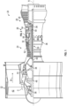
- FIG. 1 schematically illustrates a gas turbine engine 20.
- the gas turbine engine 20 is disclosed herein as a two-spool turbofan that generally incorporates a fan section 22, a compressor section 24, a combustor section 26 and a turbine section 28.
- Alternative engines might include other systems or features.
- the fan section 22 drives air along a bypass flow path B in a bypass duct, while the compressor section 24 drives air along a core flow path C for compression and communication into the combustor section 26 then expansion through the turbine section 28.
- FIG. 1 schematically illustrates a gas turbine engine 20.
- the gas turbine engine 20 is disclosed herein as a two-spool turbofan that generally incorporates a fan section 22, a compressor section 24, a combustor section 26 and a turbine section 28.
- Alternative engines might include other systems or features.
- the fan section 22 drives air along a bypass flow path B in a bypass duct
- the compressor section 24 drives air along a core flow path C for compression and communication into the combustor section 26
- the exemplary engine 20 generally includes a low speed spool 30 and a high speed spool 32 mounted for rotation about an engine central longitudinal axis A relative to an engine static structure 36 via several bearing systems 38. It should be understood that various bearing systems 38 at various locations may alternatively or additionally be provided, and the location of bearing systems 38 may be varied as appropriate to the application.
- the low speed spool 30 generally includes an inner shaft 40 that interconnects a fan 42, a low pressure compressor 44 and a low pressure turbine 46.
- the inner shaft 40 is connected to the fan 42 through a speed change mechanism, which in exemplary gas turbine engine 20 is illustrated as a geared architecture 48 to drive the fan 42 at a lower speed than the low speed spool 30.
- the high speed spool 32 includes an outer shaft 50 that interconnects a high pressure compressor 52 and high pressure turbine 54.
- a combustor 56 is arranged in exemplary gas turbine 20 between the high pressure compressor 52 and the high pressure turbine 54.
- An engine static structure 36 is arranged generally between the high pressure turbine 54 and the low pressure turbine 46.
- the engine static structure 36 further supports bearing systems 38 in the turbine section 28.
- the inner shaft 40 and the outer shaft 50 are concentric and rotate via bearing systems 38 about the engine central longitudinal axis A which is collinear with their longitudinal axes.
- each of the positions of the fan section 22, compressor section 24, combustor section 26, turbine section 28, and fan drive gear system 48 may be varied.
- gear system 48 may be located aft of combustor section 26 or even aft of turbine section 28, and fan section 22 may be positioned forward or aft of the location of gear system 48.
- the engine 20 in one example is a high-bypass geared aircraft engine.
- the geared architecture 48 may be an epicycle gear train, such as a planetary gear system or other gear system. It should be understood, however, that the above parameters are only exemplary of one embodiment of a geared architecture engine and that the present disclosure is applicable to other gas turbine engines including direct drive turbofans.
- a significant amount of thrust is provided by the bypass flow B due to the high bypass ratio.
- a diffuser 90 directs air to the combustor 56 from the high-pressure compressor 52.
- the combustor 56 includes a case 100 that defines a plurality of case apertures, generally reference as 105 and discussed in greater detail below.
- the diffuser 90 is located at a forward end of the combustor case 100.
- a liner 110 is within the case 100 and the liner 110 surrounds a combustion zone 120.
- the combustor 56 includes a dome 140 and a snout 150, which is an extension of the dome 140, and a swirler 160.
- the snout 150 is an air splitter, separating airflows from the diffuser 90.
- the combustor 56 includes a fuel injector 170 having a fuel injector channel 180 that extends through a first case aperture 105A.
- the fuel channel 180 has a nozzle 190 (or opening) that opens into the combustion zone 120 via the dome 140.
- the nozzle 190 is surrounded by the swirler 160 and snout 150. Air flows through the dome 140 and swirler 160 as it enters the combustion zone 120 to mix with the fuel from the fuel injector 170 and form a combustible mixture.
- Liner apertures, generally referenced as 200 include for example three liner apertures 200A, 200B, 200C that direct air into the combustion zone 120 to cool and condition the combustion products.
- An igniter 210 extends thorough the case 100 via second case aperture 105B for igniting the combustible mixture and providing a flame.
- a flame sensor 220 is provided.
- the flame sensor 220 includes a radio frequency (RF) transponder (for simplicity, a transponder) 230.
- the transponder 230 includes a transmitter-receiver pair.
- the transponder 230 is operationally coupled to a controller 235, which may be an engine controller or other controller.
- the transponder may operate in frequencies between the GHz to THz, and more specifically within the range 1GHz and 140 GHz, in time partition transmission and reception, as discussed in greater detail below.
- a tubular waveguide 240 extends from the Transponder 230 to a microwave horn antenna (for simplicity, a horn) 250 in the nozzle 190 to sense conditions of the flame.
- the waveguide 240 is a transverse electromagnetic transmission line, a hollow tube, a dielectrically filled tube or an air filled tube.
- the horn 250 includes a lens 255 formed of one or more of a dielectric and a metal.
- the waveguide 240 can be a tubular device, or can be a dielectric waveguide, or some combination.
- the waveguide 240 may be provided in various configurations, e.g., along various paths, between the transponder 230 and the horn 250.
- a first configuration of the waveguide 240 FIG. 2A
- the waveguide 240 may extend to the nozzle 190 via the first case aperture 105A, e.g., within the fuel channel 180.
- a cavity 195 (schematically shown) is provided in and through the fuel nozzle 190 to accommodate the horn, one cavity for each fuel nozzle.
- performance of the fuel nozzles can be compared, e.g., by comparing an absolute and relative fuel nozzle to all the other fuel nozzles. This configuration would enable the use of feedback control on the fuel nozzles to improve pattern factor and thus improve engine performance.
- the waveguide 240 may extend to the nozzle 190 via the second case aperture 105B, e.g., adjacent to the igniter 210.
- the waveguide 240 may extend to the nozzle 190 via a third case aperture 105C that is spaced apart from the first and second case apertures 105A, 105B.
- the waveguide 240 could be contained within the igniter 210, aligned along the length, which allows orthogonal imaging of the flame, allowing characterization of the entire flame front. Aligning the waveguide 240 along the nozzle 190 allows for lengthwise imaging and thus requires a smaller field of view and will be more compact.
- the different configurations of the waveguide 240 are not intended in limiting the configuration of the embodiments. It is to be appreciated that extending the waveguide through the first or second apertures 105A, 105B avoids having to form the third aperture 105C in the combustor case 100, which may be thermally efficient.
- the combustor 56 has a plurality of fuel injectors 170 with a corresponding plurality of fuel channels 180 and related nozzles 190.
- a plurality of the horns 250 may be provided, with one of the horns 250 being disposed in each of the nozzles 190.
- a corresponding plurality of waveguides 240 may extend from the same transponder 230, or optionally multiple transponders 230, to respective ones of the horns 250.
- the different waveguides may each couple with the respective horns 250 via one of the configurations ( FIGS. 2A-2C )disclosed herein.
- the flame sensor 220 may be configured to control a transmission frequency from the Transponder 230. This enables determining one or more of a density, a mobility, and a temperature of the flame.
- the flame sensor 220 may be configured to control a polarization of the transmission from the Transponder 230. This enables obtaining data for a fluid dynamic analysis of the flow field of the fuel for imaging the flow field. This analysis enables, e.g., identifying when an impediment is within the fuel channel 180.
- the flame sensor 220 may be configured to control a waveform mode from the transponder 230. This provides for detecting different portions of the flame, to perform flame and flow field diagnostics in two or three dimensions.
- the flame sensor 220 may be configured to measure a reflective intensity of the flame. This enables the determination of an intensity of combustion.
- a plurality of waveguides 240 are coupled between the transponder 230 and a plurality of horns 250 that are located in different ones of a plurality of the nozzles 190.
- the flame sensor 220 may be configured to multiplex signals through the different waveguides 240. This enables performing flame and flow field diagnostics at each of the nozzles 190.
- the plasma nature of flames is exploited to diagnose the presence and quality of a flame emanating from combustion found in the combustor 56.
- Combustion creates a mixture a electrically conductive plasma that acts to reflect radio frequency waves similar to a sheet of metal.
- Electromagnetic radiation can be used to sense the presence or absence of a flame, thereby enabling a pattern factor determination for the flame.
- the embodiments provide a radio frequency transmission and receiving transponder 230 operating at frequencies between the GHz to THz.
- the transponder 230 operating in this range creates radio frequency energy that impinges upon the flame, if it is present, with some portion of the incident energy reflected back, based on the volumetric extent of the flame. If the flame is not present, e.g., due to a blockage in the fuel channel 180, then the reflected signal is near zero, indicating a flame-out situation.
- the frequency, polarization, directions by choice of mode shapes, and intensity of the electromagnetic radiation the extent and intensity of the flame can be determined.
- a forward signal and reflected signal may be characterized by the system scattering parameters (sometimes referred to as S parameters).
- S parameters the system scattering parameters
- the disclosed sensor 220 provides for other detection schemes including reflection coefficient schemes, standing wave ration schemes, as nonlimiting examples.
- S 11 which indicates the backscattered radiation, will depend upon whether the flame is present and its spatial extent. It should be appreciated that a fully reflective surface has an S11 value of 0dB, while a fully transmissive system has an S11 value of less than -50bB or more, though these values are typically ideal and not obtained in practice.
- FIG. 3 a flowchart shows a method of performing flame and flow field diagnostics in a combustor of a gas turbine engine.
- the method includes directing an airflow into the combustion zone 120 of the combustor 56.
- the method includes directing fuel, via the fuel channel 180 and the fuel nozzle 190, into the combustion zone 120 to provide a combustion mixture with the airflow.
- the method includes igniting the combustion mixture to provide the flame.
- the method includes performing flame and flow field diagnostics with a flame sensor 220 via the transponder 230, a horn 250 in the fuel nozzle 190, and a tubular waveguide 240 extending between the transponder 230 and the horn 250.
- the method includes controlling a transmission frequency from the transponder 220 to determine one or more of a density, a mobility, and a temperature of the flame.
- the method includes controlling a polarization of the transmission from the transponder 220, to obtain data for a fluid dynamic analysis of the flow field of the fuel for imaging the flow field.
- the method includes controlling a waveform mode from the transponder 220 to provide for the detecting of different portions of the flame to perform flame and flow field diagnostics in two or three dimensions.
- the method includes measuring with the flame sensor 220 a reflective intensity of the flame to determine an intensity of combustion.
- the flame sensor 220 can determine not only the presence of the flame, but provide diagnostics of it: intensity, spatial extent, temperature, % combustion, flow field dynamics, etc.
- the sensor 220 is configured for controlling output polarization. Selecting the electromagnetic polarization allows the impinging wave to determine the flow stream of the charge carriers and therefore allows both fluid dynamic analysis and the ability to image the flow fields.
- the sensor 220 is configured for controlling output frequency. By varying frequency, the sensor 220 can determine carrier density, mobility, and temperature of the flame, which is useful in understanding flame dynamics.
- the sensor 220 is configured for controlling an output mode. Mode shape allows the detecting of various portions of the flame, thereby enabling performing of flame and flow field diagnostics in two or three dimensions, e.g., to provide a flame shape.
- the transponder 230 typically a forward signal and reflected signal are characterized by the system scattering parameters (sometimes referred to as S parameters). However, the sensor 220 provides for other detection schemes including reflection coefficient schemes, and standing wave ration schemes, as nonlimiting examples.
- the sensor 220 is configured for measuring reflective intensity. By measuring the reflected intensity, the sensor 220 can determine the degree of combustion.
- the sensor 220 can be used as a point sensor for minimal diagnostics.
- the sensor 220 is configured for multiplexing. That is, a single or multiple transponders constituting a transmitter and receiver (Tx/Rx) can enable multi-burner detecting (or sensing), to reduce costs, size, weight, and power requirements of the sensor 220.
- the sensor 220 can operate in continuous wave (CW) or pulsed power with time allocations to sensing position of the flame and to allow the same waveguide 240 to be used to both send and receive diagnostic signals.
- the sensor 220 is configured for controlling the output frequency.
- the interrogation frequency of interest is from 1GHz up to 1 THz, and more specifically within the range 10GHz and 140 GHz.
- the waveguide 240 may include a stripline, it may be hollow, it may have a dielectric fill, air fill, it may be circular, rectangular, etc.
- the horn 250 also can be circular, rectangular, etc.
- the horn 250 can be optionally fitted with a lens 255, which can be made of dielectric, metal or the combination of metal and dielectric.
- the embodiments utilize GHz to THz based radio frequency reflectometry to detect and image a flame to determine the pattern factor from a fuel nozzle 190.
- the embodiments provide for varying polarization, mode shape, frequency and phase of an incident radio frequency signal to spatially detect a combustor flame.
- the embodiments measure the reflected radiation from the flame in time partition transmission and reception.
- the embodiments use a radio frequency transponder 230 placed remote to the region of ignition, e.g., the combustion zone 120, with waveguided transmissions and reception.
- the utilization of a radio frequency solution enables the sensing to occur beyond line of sight, e.g., which might occur with an optical sensor solution.
Landscapes
- Engineering & Computer Science (AREA)
- Chemical & Material Sciences (AREA)
- Combustion & Propulsion (AREA)
- Mechanical Engineering (AREA)
- General Engineering & Computer Science (AREA)
- Testing Of Engines (AREA)
Abstract
A combustor (56) including: a combustor case (100) defining a plurality of case apertures (105A, 105B); a liner (110) within the combustor case (100) defining a combustion zone (120) and liner apertures (200A, 200B, 200C) through which an airflow flows into the combustion zone (120); a fuel injector (170) having a fuel channel (180) extending through a first case aperture (105A) and the liner (110), and the fuel channel (180) has a nozzle (190) at the combustion zone (120) through which fuel is injected; an igniter (210) for igniting the combustible mixture of fuel and airflow and providing a flame at the nozzle (190); and a flame sensor (220) including: a radio frequency transponder (230), comprising a transmitter-receiver pair, located exterior to the combustor case (100); a horn antenna (250) disposed in the fuel nozzle (190), and a tubular waveguide (240) extending from the radio frequency transponder (230) to the horn (250) via one of the plurality of case apertures (105A, 105B), wherein the flame sensor (220) is configured to perform flame and flow field diagnostics.
Description
- Exemplary embodiments of the present disclosure pertain to the art of combustors of gas turbine engines and more specifically to a system and method for performing flame and flow field diagnostics in a combustor of a gas turbine engine.
- A gas turbine engine requires the combustor to reliably produce a flame. Testing a flame production in a newly designed combustor and monitoring the flame production in an in-use combustor can help identify and correct issues that could otherwise lead to an inefficient operation of the engine.
- Disclosed is a combustor of a gas turbine engine according to an aspect of the present invention, including: a combustor case defining a plurality of case apertures; a liner within the combustor case defining a combustion zone and liner apertures through which an airflow flows into the combustion zone; a fuel injector having a fuel channel extending through a first case aperture and the liner, and the fuel channel has a nozzle at the combustion zone through which fuel is injected, to produce a combustible mixture with the airflow; an igniter extending through a second case aperture and the liner for igniting the combustible mixture and providing a flame at the nozzle; and a flame sensor including: a radio frequency transponder, comprising a transmitter-receiver pair, located exterior to the combustor case; a horn antenna disposed in the fuel nozzle, and a tubular waveguide extending from the radio frequency transponder to the horn via one of the plurality of case apertures, wherein the flame sensor is configured to perform flame and flow field diagnostics.
- In an embodiment of the above, the flame sensor is configured to determine the presence of the flame.
- In an embodiment according to any of the previous embodiments, the flame sensor is configured to control a polarization of a transmission from the radio frequency transponder, to obtain data for a fluid dynamic analysis of a flow field of the fuel for imaging the flow field.
- In an embodiment according to any of the previous embodiments, the flame sensor is configured to control a waveform mode from the radio frequency transponder to provide for detecting different portions of the flame, to perform flame and flow field diagnostics in two or three dimensions.
- In an embodiment according to any of the previous embodiments, the flame sensor is configured to measure a reflective intensity of the flame to determine an intensity of combustion.
- In an embodiment according to any of the previous embodiments, the waveguide is one of: a transverse electromagnetic transmission line; a hollow tube; a dielectrically filled tube; and an air filled tube.
- In an embodiment according to any of the previous embodiments, the horn includes a lens formed of one or more of a dielectric and a metal.
- Further disclosed is a gas turbine engine according to another aspect of the present invention, including: a combustor that includes: a combustor case defining a plurality of case apertures; a liner within the combustor case defining a combustion zone and liner apertures through which an airflow flows into the combustion zone; a fuel injector having a fuel channel extending through a first case aperture and the liner, and the fuel channel has a nozzle at the combustion zone through which fuel is injected, to produce a combustible mixture with the airflow; an igniter extending through a second case aperture and the liner for igniting the combustible mixture and providing a flame at the nozzle; and a flame sensor including: a radio frequency transponder, comprising a transmitter-receiver pair, located exterior to the combustor case; a horn disposed in the fuel nozzle, and a tubular waveguide extending from the radio frequency transponder to the horn via one of the plurality of case apertures, wherein the flame sensor is configured to perform flame and flow field diagnostics.
- In an embodiment of the above, the flame sensor is configured to determine the presence of the flame.
- In an embodiment according to any of the previous embodiments, the flame sensor is configured to control a polarization of a transmission, to obtain data for a fluid dynamic analysis of a flow field of the fuel for imaging the flow field.
- In an embodiment according to any of the previous embodiments, the flame sensor is configured to control a waveform mode to provide for detecting different portions of the flame, whereby the flame sensor performs flame and flow field diagnostics in two or three dimensions.
- In an embodiment according to any of the previous embodiments, the flame sensor is configured to measure a reflective intensity of the flame to determine an intensity of combustion.
- In an embodiment according to any of the previous embodiments, the waveguide is one of: a transverse electromagnetic transmission line; a hollow tube; a dielectrically filled tube; and an air filled tube.
- In an embodiment according to any of the previous embodiments, the horn includes a lens formed of one or more of a dielectric and a metal.
- In an embodiment according to any of the previous embodiments, the engine includes: an inlet; a compressor downstream of the inlet; a turbine downstream of the compressor; and an exhaust downstream of the turbine, wherein the combustor is between the compressor and the turbine.
- Further disclosed is a method of performing flame and flow field diagnostics in a combustor of a gas turbine engine according to another aspect of the present invention, the method including: directing an airflow into a combustion zone of the combustor; (e.g. horn antenna) directing fuel, via a fuel injector channel and a fuel nozzle, into the combustion zone to provide a combustion mixture with the airflow; igniting the combustion mixture to provide the flame; and performing flame and flow field diagnostics with a flame sensor via a radio frequency transponder comprising a transmitter-receiver pair, a horn in the fuel nozzle, and a tubular waveguide extending between the radio frequency transponder and the horn.
- In an embodiment of the above, the method includes determining with the flame sensor the presence of the flame.
- In an embodiment according to any of the previous embodiments, the method includes controlling a polarization of a transmission from the radio frequency transponder, to obtain data for a fluid dynamic analysis of a flow field of the fuel for imaging the flow field.
- In an embodiment according to any of the previous embodiments, the method includes controlling a waveform mode from the radio frequency transponder to provide for detecting different portions of the flame to perform flame and flow field diagnostics in two or three dimensions.
- In an embodiment according to any of the previous embodiments, the method includes measuring with the flame sensor a reflective intensity of the flame to determine an intensity of combustion.
- The following descriptions should not be considered limiting in any way. With reference to the accompanying drawings, like elements are numbered alike:
-
FIG. 1 is a partial cross-sectional view of a gas turbine engine; -
FIG. 2A shows details of a combustor configured for performing flame and flow field diagnostics in a combustor of a gas turbine engine, with a guide wire and horn antenna of the sensor in a first configuration; -
FIG. 2B the combustor configuration ofFIG. 2A , with the guide wire and horn antenna of the sensor in a second configuration; -
FIG. 2C the combustor configuration ofFIG. 2A , with the guide wire and horn antenna of the sensor in a third configuration; and -
FIG. 3 is a flowchart showing a method of performing flame and flow field diagnostics in a combustor of a gas turbine engine. - A detailed description of one or more embodiments of the disclosed apparatus and method are presented herein by way of exemplification and not limitation with reference to the Figures.
-
FIG. 1 schematically illustrates agas turbine engine 20. Thegas turbine engine 20 is disclosed herein as a two-spool turbofan that generally incorporates afan section 22, acompressor section 24, acombustor section 26 and aturbine section 28. Alternative engines might include other systems or features. Thefan section 22 drives air along a bypass flow path B in a bypass duct, while thecompressor section 24 drives air along a core flow path C for compression and communication into thecombustor section 26 then expansion through theturbine section 28. Although depicted as a two-spool turbofan gas turbine engine in the disclosed non-limiting embodiment, it should be understood that the concepts described herein are not limited to use with two-spool turbofans as the teachings may be applied to other types of turbine engines including three-spool architectures. - The
exemplary engine 20 generally includes alow speed spool 30 and ahigh speed spool 32 mounted for rotation about an engine central longitudinal axis A relative to an enginestatic structure 36 viaseveral bearing systems 38. It should be understood thatvarious bearing systems 38 at various locations may alternatively or additionally be provided, and the location ofbearing systems 38 may be varied as appropriate to the application. - The
low speed spool 30 generally includes aninner shaft 40 that interconnects afan 42, alow pressure compressor 44 and a low pressure turbine 46. Theinner shaft 40 is connected to thefan 42 through a speed change mechanism, which in exemplarygas turbine engine 20 is illustrated as a gearedarchitecture 48 to drive thefan 42 at a lower speed than thelow speed spool 30. Thehigh speed spool 32 includes anouter shaft 50 that interconnects ahigh pressure compressor 52 andhigh pressure turbine 54. Acombustor 56 is arranged inexemplary gas turbine 20 between thehigh pressure compressor 52 and thehigh pressure turbine 54. An enginestatic structure 36 is arranged generally between thehigh pressure turbine 54 and the low pressure turbine 46. The enginestatic structure 36 further supports bearingsystems 38 in theturbine section 28. Theinner shaft 40 and theouter shaft 50 are concentric and rotate viabearing systems 38 about the engine central longitudinal axis A which is collinear with their longitudinal axes. - The core airflow is compressed by the
low pressure compressor 44 then thehigh pressure compressor 52, mixed and burned with fuel in thecombustor 56, then expanded over thehigh pressure turbine 54 and low pressure turbine 46. Theturbines 46, 54 rotationally drive the respectivelow speed spool 30 andhigh speed spool 32 in response to the expansion. It will be appreciated that each of the positions of thefan section 22,compressor section 24,combustor section 26,turbine section 28, and fandrive gear system 48 may be varied. For example,gear system 48 may be located aft ofcombustor section 26 or even aft ofturbine section 28, andfan section 22 may be positioned forward or aft of the location ofgear system 48. - The
engine 20 in one example is a high-bypass geared aircraft engine. The gearedarchitecture 48 may be an epicycle gear train, such as a planetary gear system or other gear system. It should be understood, however, that the above parameters are only exemplary of one embodiment of a geared architecture engine and that the present disclosure is applicable to other gas turbine engines including direct drive turbofans. - A significant amount of thrust is provided by the bypass flow B due to the high bypass ratio.
- Turning to
FIGS. 2A-2C , adiffuser 90 directs air to thecombustor 56 from the high-pressure compressor 52. Thecombustor 56 includes acase 100 that defines a plurality of case apertures, generally reference as 105 and discussed in greater detail below. Thediffuser 90 is located at a forward end of thecombustor case 100. Aliner 110 is within thecase 100 and theliner 110 surrounds acombustion zone 120. Thecombustor 56 includes adome 140 and asnout 150, which is an extension of thedome 140, and aswirler 160. Thesnout 150 is an air splitter, separating airflows from thediffuser 90. - The
combustor 56 includes afuel injector 170 having afuel injector channel 180 that extends through afirst case aperture 105A. Thefuel channel 180 has a nozzle 190 (or opening) that opens into thecombustion zone 120 via thedome 140. Thenozzle 190 is surrounded by theswirler 160 andsnout 150. Air flows through thedome 140 andswirler 160 as it enters thecombustion zone 120 to mix with the fuel from thefuel injector 170 and form a combustible mixture. Liner apertures, generally referenced as 200, include for example threeliner apertures combustion zone 120 to cool and condition the combustion products. Anigniter 210 extends thorough thecase 100 viasecond case aperture 105B for igniting the combustible mixture and providing a flame. - According to an embodiment, a
flame sensor 220 is provided. Theflame sensor 220 includes a radio frequency (RF) transponder (for simplicity, a transponder) 230. Thetransponder 230 includes a transmitter-receiver pair. Thetransponder 230 is operationally coupled to acontroller 235, which may be an engine controller or other controller. The transponder may operate in frequencies between the GHz to THz, and more specifically within the range 1GHz and 140 GHz, in time partition transmission and reception, as discussed in greater detail below. Atubular waveguide 240 extends from theTransponder 230 to a microwave horn antenna (for simplicity, a horn) 250 in thenozzle 190 to sense conditions of the flame. In one embodiment, thewaveguide 240 is a transverse electromagnetic transmission line, a hollow tube, a dielectrically filled tube or an air filled tube. In one embodiment, thehorn 250 includes alens 255 formed of one or more of a dielectric and a metal. Specifically, thewaveguide 240 can be a tubular device, or can be a dielectric waveguide, or some combination. - The
waveguide 240 may be provided in various configurations, e.g., along various paths, between thetransponder 230 and thehorn 250. In a first configuration of the waveguide 240 (FIG. 2A ), thewaveguide 240 may extend to thenozzle 190 via thefirst case aperture 105A, e.g., within thefuel channel 180. In one embodiment, a cavity 195 (schematically shown) is provided in and through thefuel nozzle 190 to accommodate the horn, one cavity for each fuel nozzle. With this configuration, performance of the fuel nozzles can be compared, e.g., by comparing an absolute and relative fuel nozzle to all the other fuel nozzles. This configuration would enable the use of feedback control on the fuel nozzles to improve pattern factor and thus improve engine performance. - In a second configuration of the waveguide 240 (
FIG. 2B ), thewaveguide 240 may extend to thenozzle 190 via thesecond case aperture 105B, e.g., adjacent to theigniter 210. In a third configuration of the waveguide 240 (FIG. 2C ), thewaveguide 240 may extend to thenozzle 190 via athird case aperture 105C that is spaced apart from the first andsecond case apertures - That is, the
waveguide 240 could be contained within theigniter 210, aligned along the length, which allows orthogonal imaging of the flame, allowing characterization of the entire flame front. Aligning thewaveguide 240 along thenozzle 190 allows for lengthwise imaging and thus requires a smaller field of view and will be more compact. The different configurations of thewaveguide 240 are not intended in limiting the configuration of the embodiments. It is to be appreciated that extending the waveguide through the first orsecond apertures third aperture 105C in thecombustor case 100, which may be thermally efficient. - In one embodiment, the
combustor 56 has a plurality offuel injectors 170 with a corresponding plurality offuel channels 180 andrelated nozzles 190. A plurality of thehorns 250 may be provided, with one of thehorns 250 being disposed in each of thenozzles 190. A corresponding plurality ofwaveguides 240 may extend from thesame transponder 230, or optionallymultiple transponders 230, to respective ones of thehorns 250. The different waveguides may each couple with therespective horns 250 via one of the configurations (FIGS. 2A-2C )disclosed herein. - In one embodiment, the
flame sensor 220 may be configured to control a transmission frequency from theTransponder 230. This enables determining one or more of a density, a mobility, and a temperature of the flame. - In one embodiment, the
flame sensor 220 may be configured to control a polarization of the transmission from theTransponder 230. This enables obtaining data for a fluid dynamic analysis of the flow field of the fuel for imaging the flow field. This analysis enables, e.g., identifying when an impediment is within thefuel channel 180. - In one embodiment, the
flame sensor 220 may be configured to control a waveform mode from thetransponder 230. This provides for detecting different portions of the flame, to perform flame and flow field diagnostics in two or three dimensions. - In one embodiment, the
flame sensor 220 may be configured to measure a reflective intensity of the flame. This enables the determination of an intensity of combustion. - As indicated, in one embodiment, a plurality of
waveguides 240 are coupled between thetransponder 230 and a plurality ofhorns 250 that are located in different ones of a plurality of thenozzles 190. In this embodiment, theflame sensor 220 may be configured to multiplex signals through thedifferent waveguides 240. This enables performing flame and flow field diagnostics at each of thenozzles 190. - With the disclosed embodiments, the plasma nature of flames is exploited to diagnose the presence and quality of a flame emanating from combustion found in the
combustor 56. Combustion creates a mixture a electrically conductive plasma that acts to reflect radio frequency waves similar to a sheet of metal. Electromagnetic radiation can be used to sense the presence or absence of a flame, thereby enabling a pattern factor determination for the flame. - The embodiments provide a radio frequency transmission and receiving
transponder 230 operating at frequencies between the GHz to THz. Thetransponder 230 operating in this range creates radio frequency energy that impinges upon the flame, if it is present, with some portion of the incident energy reflected back, based on the volumetric extent of the flame. If the flame is not present, e.g., due to a blockage in thefuel channel 180, then the reflected signal is near zero, indicating a flame-out situation. By varying the frequency, polarization, directions by choice of mode shapes, and intensity of the electromagnetic radiation, the extent and intensity of the flame can be determined. As the detecting (or interrogation) can occur in nanoseconds, multiple flames from several of thenozzles 190 may be analyzed using thesame flame sensor 220. Further, typically a forward signal and reflected signal may be characterized by the system scattering parameters (sometimes referred to as S parameters). However, the disclosedsensor 220 provides for other detection schemes including reflection coefficient schemes, standing wave ration schemes, as nonlimiting examples. For example, the value of S 11, which indicates the backscattered radiation, will depend upon whether the flame is present and its spatial extent. It should be appreciated that a fully reflective surface has an S11 value of 0dB, while a fully transmissive system has an S11 value of less than -50bB or more, though these values are typically ideal and not obtained in practice. - Turning to
FIG. 3 , a flowchart shows a method of performing flame and flow field diagnostics in a combustor of a gas turbine engine. As shown inblock 310 the method includes directing an airflow into thecombustion zone 120 of thecombustor 56. As shown inblock 320 the method includes directing fuel, via thefuel channel 180 and thefuel nozzle 190, into thecombustion zone 120 to provide a combustion mixture with the airflow. As shown inblock 330 the method includes igniting the combustion mixture to provide the flame. - As shown in
block 340 the method includes performing flame and flow field diagnostics with aflame sensor 220 via thetransponder 230, ahorn 250 in thefuel nozzle 190, and atubular waveguide 240 extending between thetransponder 230 and thehorn 250. As shown inblock 350 the method includes controlling a transmission frequency from thetransponder 220 to determine one or more of a density, a mobility, and a temperature of the flame. As shown inblock 360 the method includes controlling a polarization of the transmission from thetransponder 220, to obtain data for a fluid dynamic analysis of the flow field of the fuel for imaging the flow field. As shown inblock 370, the method includes controlling a waveform mode from thetransponder 220 to provide for the detecting of different portions of the flame to perform flame and flow field diagnostics in two or three dimensions. As shown inblock 380 the method includes measuring with the flame sensor 220 a reflective intensity of the flame to determine an intensity of combustion. In other words, theflame sensor 220 can determine not only the presence of the flame, but provide diagnostics of it: intensity, spatial extent, temperature, % combustion, flow field dynamics, etc. - As indicated, the
sensor 220 is configured for controlling output polarization. Selecting the electromagnetic polarization allows the impinging wave to determine the flow stream of the charge carriers and therefore allows both fluid dynamic analysis and the ability to image the flow fields. Thesensor 220 is configured for controlling output frequency. By varying frequency, thesensor 220 can determine carrier density, mobility, and temperature of the flame, which is useful in understanding flame dynamics. Thesensor 220 is configured for controlling an output mode. Mode shape allows the detecting of various portions of the flame, thereby enabling performing of flame and flow field diagnostics in two or three dimensions, e.g., to provide a flame shape. With thetransponder 230, typically a forward signal and reflected signal are characterized by the system scattering parameters (sometimes referred to as S parameters). However, thesensor 220 provides for other detection schemes including reflection coefficient schemes, and standing wave ration schemes, as nonlimiting examples. Thesensor 220 is configured for measuring reflective intensity. By measuring the reflected intensity, thesensor 220 can determine the degree of combustion. - With the use of the
horn 250, thesensor 220 can be used as a point sensor for minimal diagnostics. Thesensor 220 is configured for multiplexing. That is, a single or multiple transponders constituting a transmitter and receiver (Tx/Rx) can enable multi-burner detecting (or sensing), to reduce costs, size, weight, and power requirements of thesensor 220. Thesensor 220 can operate in continuous wave (CW) or pulsed power with time allocations to sensing position of the flame and to allow thesame waveguide 240 to be used to both send and receive diagnostic signals. Thesensor 220 is configured for controlling the output frequency. The interrogation frequency of interest is from 1GHz up to 1 THz, and more specifically within the range 10GHz and 140 GHz. Thewaveguide 240 may include a stripline, it may be hollow, it may have a dielectric fill, air fill, it may be circular, rectangular, etc. Thehorn 250 also can be circular, rectangular, etc. Thehorn 250 can be optionally fitted with alens 255, which can be made of dielectric, metal or the combination of metal and dielectric. - In sum, the embodiments utilize GHz to THz based radio frequency reflectometry to detect and image a flame to determine the pattern factor from a
fuel nozzle 190. The embodiments provide for varying polarization, mode shape, frequency and phase of an incident radio frequency signal to spatially detect a combustor flame. The embodiments measure the reflected radiation from the flame in time partition transmission and reception. The embodiments use aradio frequency transponder 230 placed remote to the region of ignition, e.g., thecombustion zone 120, with waveguided transmissions and reception. In addition, the utilization of a radio frequency solution enables the sensing to occur beyond line of sight, e.g., which might occur with an optical sensor solution. - The term "about" is intended to include the degree of error associated with measurement of the particular quantity based upon the equipment available at the time of filing the application.
- The terminology used herein is for the purpose of describing particular embodiments only and is not intended to be limiting of the present disclosure. As used herein, the singular forms "a", "an" and "the" are intended to include the plural forms as well, unless the context clearly indicates otherwise. It will be further understood that the terms "comprises" and/or "comprising," when used in this specification, specify the presence of stated features, integers, steps, operations, elements, and/or components, but do not preclude the presence or addition of one or more other features, integers, steps, operations, element components, and/or groups thereof.
- While the present disclosure has been described with reference to an exemplary embodiment or embodiments, it will be understood by those skilled in the art that various changes may be made and equivalents may be substituted for elements thereof without departing from the scope of the present disclosure. In addition, many modifications may be made to adapt a particular situation or material to the teachings of the present disclosure without departing from the essential scope thereof. Therefore, it is intended that the present disclosure not be limited to the particular embodiment disclosed as the best mode contemplated for carrying out this present disclosure, but that the present disclosure will include all embodiments falling within the scope of the claims.
Claims (15)
- A combustor of a gas turbine engine, comprising:a combustor case (100) defining a plurality of case apertures (105A, 105B);a liner (110) within the combustor case (100) defining a combustion zone (120) and liner apertures (200A, 200B, 200C) through which an airflow flows into the combustion zone (120);a fuel injector (170) having a fuel channel (180) extending through a first case aperture (105A) and the liner (110), wherein the fuel channel (180) has a nozzle (190) at the combustion zone (120) through which fuel is injected, to produce a combustible mixture with the airflow;an igniter (210) extending through a second case aperture (105B) and the liner (110) for igniting the combustible mixture and providing a flame at the nozzle (190); anda flame sensor (220) including:a radio frequency transponder (230), comprising a transmitter-receiver pair, located exterior to the combustor case (100); anda horn antenna (250) disposed in the nozzle (190), and a tubular waveguide (240) extending from the radio frequency transponder (230) to the horn antenna (250) via one of the plurality of case apertures (105A, 105B), wherein the flame sensor (220) is configured to perform flame and flow field diagnostics.
- The combustor of claim 1, wherein the flame sensor (220) is configured to determine the presence of the flame.
- The combustor of claim 1 or 2, wherein the flame sensor (220) is configured to control a polarization of a transmission from the radio frequency transponder (230), to obtain data for a fluid dynamic analysis of a flow field of the fuel for imaging the flow field.
- The combustor of any preceding claim, wherein the flame sensor (220) is configured to control a waveform mode from the radio frequency transponder (230) to provide for detecting different portions of the flame, to perform flame and flow field diagnostics in two or three dimensions.
- The combustor of any preceding claim, wherein the flame sensor (220) is configured to measure a reflective intensity of the flame to determine an intensity of combustion.
- The combustor of any preceding claim, wherein the tubular waveguide (240) is one of: a transverse electromagnetic transmission line; a hollow tube; a dielectrically filled tube; and an air filled tube.
- The combustor of any preceding claim, wherein the horn antenna (250) includes a lens (255) formed of a dielectric and/or a metal.
- A gas turbine engine comprising the combustor (56) of any preceding claim.
- The gas turbine engine of claim 8, wherein:the flame sensor (220) is configured to control a or the polarization of a transmission, to obtain a or the data for a or the fluid dynamic analysis of a or the flow field of the fuel for imaging the flow field; and/orthe flame sensor (220) is configured to control a or the waveform mode to provide for detecting different portions of the flame, whereby the flame sensor (220) performs flame and flow field diagnostics in two or three dimensions.
- The gas turbine engine of claim 8 or 9, further comprising:an inlet;a compressor (44, 52) downstream of the inlet;a turbine (46, 54) downstream of the compressor (44, 52); andan exhaust downstream of the turbine (46, 54), wherein the combustor (56) is between the compressor (44, 52) and the turbine (46, 54).
- A method of performing flame and flow field diagnostics in a combustor (56) of a gas turbine engine (20), the method comprising:directing an airflow into a combustion zone (120) of the combustor (56);directing fuel, via a fuel injector channel (180) and a fuel nozzle (190), into the combustion zone (120) to provide a combustion mixture with the airflow;igniting the combustion mixture to provide the flame; andperforming flame and flow field diagnostics with a flame sensor (220) via a radio frequency transponder (230) comprising a transmitter-receiver pair, a horn (250) in the fuel nozzle (190), and a tubular waveguide (240) extending between the radio frequency transponder (230) and the horn (250).
- The method of claim 11, further comprising determining with the flame sensor (220) the presence of the flame.
- The method of claim 11 or 12, further comprising controlling a polarization of a transmission from the radio frequency transponder (230), to obtain data for a fluid dynamic analysis of a flow field of the fuel for imaging the flow field.
- The method of claim 11, 12 or 13, further comprising controlling a waveform mode from the radio frequency transponder (230) to provide for detecting different portions of the flame to perform flame and flow field diagnostics in two or three dimensions.
- The method of any of claims 11 to 14, further comprising measuring with the flame sensor (220) a reflective intensity of the flame to determine an intensity of combustion.
Applications Claiming Priority (1)
| Application Number | Priority Date | Filing Date | Title |
|---|---|---|---|
| US202363588379P | 2023-10-06 | 2023-10-06 |
Publications (1)
| Publication Number | Publication Date |
|---|---|
| EP4542118A1 true EP4542118A1 (en) | 2025-04-23 |
Family
ID=93014743
Family Applications (1)
| Application Number | Title | Priority Date | Filing Date |
|---|---|---|---|
| EP24204992.2A Pending EP4542118A1 (en) | 2023-10-06 | 2024-10-07 | System and method for performing flame and flow field diagnostics in a combustor of a gas turbine engine |
Country Status (2)
| Country | Link |
|---|---|
| US (1) | US20250257871A1 (en) |
| EP (1) | EP4542118A1 (en) |
Citations (5)
| Publication number | Priority date | Publication date | Assignee | Title |
|---|---|---|---|---|
| EP0942232B1 (en) * | 1998-03-13 | 2005-09-21 | General Electric Company | Flame sensor with dynamic sensitivity adjustment |
| US20100186368A1 (en) * | 2007-07-12 | 2010-07-29 | Imagineering, Inc. | Ignition/ chemical reaction promotion/ flame holding device, speed-type internal combustion engine, and furnace |
| US20130291552A1 (en) * | 2012-05-03 | 2013-11-07 | United Technologies Corporation | Electrical control of combustion |
| EP3431877A1 (en) * | 2017-07-18 | 2019-01-23 | ANSALDO ENERGIA S.p.A. | Gas turbine plant for the production of electrical energy |
| EP3690414A1 (en) * | 2019-01-31 | 2020-08-05 | Rolls-Royce plc | Combustor for gas turbine engine |
-
2024
- 2024-10-07 EP EP24204992.2A patent/EP4542118A1/en active Pending
- 2024-10-07 US US18/908,030 patent/US20250257871A1/en active Pending
Patent Citations (5)
| Publication number | Priority date | Publication date | Assignee | Title |
|---|---|---|---|---|
| EP0942232B1 (en) * | 1998-03-13 | 2005-09-21 | General Electric Company | Flame sensor with dynamic sensitivity adjustment |
| US20100186368A1 (en) * | 2007-07-12 | 2010-07-29 | Imagineering, Inc. | Ignition/ chemical reaction promotion/ flame holding device, speed-type internal combustion engine, and furnace |
| US20130291552A1 (en) * | 2012-05-03 | 2013-11-07 | United Technologies Corporation | Electrical control of combustion |
| EP3431877A1 (en) * | 2017-07-18 | 2019-01-23 | ANSALDO ENERGIA S.p.A. | Gas turbine plant for the production of electrical energy |
| EP3690414A1 (en) * | 2019-01-31 | 2020-08-05 | Rolls-Royce plc | Combustor for gas turbine engine |
Also Published As
| Publication number | Publication date |
|---|---|
| US20250257871A1 (en) | 2025-08-14 |
Similar Documents
| Publication | Publication Date | Title |
|---|---|---|
| CA2785260C (en) | Device and method for monitoring rotor blades of a turbine | |
| US6473705B1 (en) | System and method for direct non-intrusive measurement of corrected airflow | |
| Peng et al. | Single-ended mid-infrared laser-absorption sensor for time-resolved measurements of water concentration and temperature within the annulus of a rotating detonation engine | |
| US20040177694A1 (en) | Apparatus for sensing pressure fluctuations in a hostile environment | |
| EP1777514B1 (en) | Method and apparatus for non-destructive testing of components of gas turbine engines made of monocrystalline materials | |
| US8786857B2 (en) | Mitigation of optical signal noise using a multimode transmit fiber | |
| US4928523A (en) | Method and apparatus for identifying ballistic characteristics within a weapon barrel | |
| JP2009516855A (en) | All-fiber architecture for built-in flight sensors for aviation propulsion applications | |
| EP3978952A1 (en) | Self-referencing microwave sensing system | |
| US8269509B2 (en) | System and method for measuring thickness of a refractory wall of a gasifier using electromagnetic energy | |
| Monfort et al. | Evaluating combustion instability in a swirl-stabilized combustor using simultaneous pressure, temperature, and chemiluminescense measurements at high repetition rates | |
| US20250257871A1 (en) | System and Method for Performing Flame and Flow Field Diagnostics in a Combustor of a Gas Turbine Engine | |
| EP2194325A1 (en) | Flame detection device and method for detecting a flame | |
| EP3978953B1 (en) | Multi-mode microwave waveguide blade sensing system | |
| CN105960564B (en) | Method for monitoring combustion installations | |
| US3838814A (en) | Nozzle area measurement | |
| US3852741A (en) | Nozzle area measurement | |
| CN101044379B (en) | Method for determining the temperature of a surface coating | |
| Chen et al. | Diagnostic in a reverse-flow aeroengine model combustor under elevated inlet pressure and temperature using spontaneous Raman | |
| US11421607B1 (en) | Fiber optic exit area sensing for gas turbine engine nozzles | |
| Weber et al. | Experimental Study of Instabilities in Hydrogen-Air Fueled Rotating Detonation Combustion | |
| Bakos et al. | The Mach 10 component of NASA's Hyper-X ground test program | |
| Huang et al. | Wave Modes in an Ethylene-Air Rotating Detonation Combustor from Fuel Lean to Rich Conditions | |
| Blackman | Studies of screeching combustion and pressure-wave, flamefront interaction | |
| Allen et al. | Diode laser sensors for aeroengines-Lessons learned and future promises |
Legal Events
| Date | Code | Title | Description |
|---|---|---|---|
| PUAI | Public reference made under article 153(3) epc to a published international application that has entered the european phase |
Free format text: ORIGINAL CODE: 0009012 |
|
| STAA | Information on the status of an ep patent application or granted ep patent |
Free format text: STATUS: THE APPLICATION HAS BEEN PUBLISHED |
|
| AK | Designated contracting states |
Kind code of ref document: A1 Designated state(s): AL AT BE BG CH CY CZ DE DK EE ES FI FR GB GR HR HU IE IS IT LI LT LU LV MC ME MK MT NL NO PL PT RO RS SE SI SK SM TR |
|
| STAA | Information on the status of an ep patent application or granted ep patent |
Free format text: STATUS: REQUEST FOR EXAMINATION WAS MADE |
|
| 17P | Request for examination filed |
Effective date: 20251020 |