EP4542113A1 - Hydrogen gas burner - Google Patents
Hydrogen gas burner Download PDFInfo
- Publication number
- EP4542113A1 EP4542113A1 EP23204020.4A EP23204020A EP4542113A1 EP 4542113 A1 EP4542113 A1 EP 4542113A1 EP 23204020 A EP23204020 A EP 23204020A EP 4542113 A1 EP4542113 A1 EP 4542113A1
- Authority
- EP
- European Patent Office
- Prior art keywords
- burner
- hydrogen
- holes
- distance
- flashback
- Prior art date
- Legal status (The legal status is an assumption and is not a legal conclusion. Google has not performed a legal analysis and makes no representation as to the accuracy of the status listed.)
- Withdrawn
Links
Images

Classifications
-
- F—MECHANICAL ENGINEERING; LIGHTING; HEATING; WEAPONS; BLASTING
- F23—COMBUSTION APPARATUS; COMBUSTION PROCESSES
- F23D—BURNERS
- F23D14/00—Burners for combustion of a gas, e.g. of a gas stored under pressure as a liquid
- F23D14/02—Premix gas burners, i.e. in which gaseous fuel is mixed with combustion air upstream of the combustion zone
- F23D14/04—Premix gas burners, i.e. in which gaseous fuel is mixed with combustion air upstream of the combustion zone induction type, e.g. Bunsen burner
- F23D14/10—Premix gas burners, i.e. in which gaseous fuel is mixed with combustion air upstream of the combustion zone induction type, e.g. Bunsen burner with elongated tubular burner head
-
- F—MECHANICAL ENGINEERING; LIGHTING; HEATING; WEAPONS; BLASTING
- F23—COMBUSTION APPARATUS; COMBUSTION PROCESSES
- F23D—BURNERS
- F23D14/00—Burners for combustion of a gas, e.g. of a gas stored under pressure as a liquid
- F23D14/46—Details
- F23D14/72—Safety devices, e.g. operative in case of failure of gas supply
- F23D14/82—Preventing flashback or blowback
-
- F—MECHANICAL ENGINEERING; LIGHTING; HEATING; WEAPONS; BLASTING
- F23—COMBUSTION APPARATUS; COMBUSTION PROCESSES
- F23C—METHODS OR APPARATUS FOR COMBUSTION USING FLUID FUEL OR SOLID FUEL SUSPENDED IN A CARRIER GAS OR AIR
- F23C2900/00—Special features of, or arrangements for combustion apparatus using fluid fuels or solid fuels suspended in air; Combustion processes therefor
- F23C2900/9901—Combustion process using hydrogen, hydrogen peroxide water or brown gas as fuel
-
- F—MECHANICAL ENGINEERING; LIGHTING; HEATING; WEAPONS; BLASTING
- F23—COMBUSTION APPARATUS; COMBUSTION PROCESSES
- F23D—BURNERS
- F23D2203/00—Gaseous fuel burners
- F23D2203/10—Flame diffusing means
- F23D2203/101—Flame diffusing means characterised by surface shape
- F23D2203/1012—Flame diffusing means characterised by surface shape tubular
-
- F—MECHANICAL ENGINEERING; LIGHTING; HEATING; WEAPONS; BLASTING
- F23—COMBUSTION APPARATUS; COMBUSTION PROCESSES
- F23D—BURNERS
- F23D2203/00—Gaseous fuel burners
- F23D2203/10—Flame diffusing means
- F23D2203/102—Flame diffusing means using perforated plates
-
- F—MECHANICAL ENGINEERING; LIGHTING; HEATING; WEAPONS; BLASTING
- F23—COMBUSTION APPARATUS; COMBUSTION PROCESSES
- F23D—BURNERS
- F23D2209/00—Safety arrangements
- F23D2209/10—Flame flashback
Definitions
- the present invention relates to a hydrogen burner comprising a burner deck having a plurality of holes, an end-cap located at a distal end of said burner deck, and a defined minimal distance between the last row of said holes and said end-cap, wherein said distance is configured to reduce the chances of flashback.
- the invention also relates to a gas boiler comprising such a hydrogen burner.
- the invention further relates to a method for reducing the risk of flashback by means of such a hydrogen burner.
- Hydrogen burners devices that combine hydrogen gas with atmospheric oxygen to produce a flame, have been a focal point of research due to their potential as an environmentally friendly alternative to carbon-based fuels. Burners must be designed to ensure efficient combustion and safety.
- One of the paramount safety concerns in hydrogen combustion is 'flashback,' a potentially hazardous condition where the flame travels back into the combustion device, potentially causing explosions or damage to the equipment.
- the object of the invention therefor is to reduce the risk of flashback by selecting a proper distance between the last row of burner holes to the endcap offering a safer and more efficient hydrogen burner design.
- a hydrogen burner comprising a burner deck having a plurality of holes, an end-cap located at a distal end of the burner deck; and a defined minimal distance between the last row of the holes and the end-cap, wherein the distance is configured to reduce the chances of flashback.
- the risk of stagnation of flow within said distance can be reduced and as the risk of flashback is reduced. If the distance would be too small, and the last row of holes would thus be too close to the end-cap, the gas flow will be disturbed by either turbulence, pressure differences or a slow down of the flow which may contribute to the flashback behavior. Thus by having a certain minimal distance, the gasflow may be more even which, additionally, also contributes into a better cooling of the burner deck near the end-cap as the gas flow also has a cooling effect when flowing properly.
- a hydrogen burner wherein the distance is between 2-10mm.
- the predefined minimum distance between the last row of holes and the end-cap falls within a range of 2-10mm. The use of this range minimizes the risk of flashback. It provides sufficient room to avoid stagnation, thereby ensuring smooth gas flow and reducing the chance of unintended flashback.
- a hydrogen burner is provided wherein the distance is between 3-6mm. This preferred range helps in ensuring an even more reduced risk of flashback while optimizing the total perforation area of the burner deck.
- a hydrogen burner is provided wherein the perforation range of the burner is around 1.6%. This particular value has been identified as an ideal percentage to ensure efficient gas mixing and flow, reducing the risk of flashback significantly.
- a hydrogen burner is provided further comprising a cone configured to decrease the volume of the burner.
- this embodiment introduces a cone structure that decreases the burner's volume. This structure is beneficial for optimizing the flow dynamics within the burner, thus further minimizing the risk of flashback.
- a hydrogen burner wherein the burner deck is fabricated through a punching process.
- the manufacturing process for the hydrogen burner deck involves a punching method. This fabrication technique allows for precise hole formations, ensuring consistency in the design and enhancing the burner's efficiency and safety.
- a gas boiler comprising a hydrogen burner according to any of the previously disclosed embodiments.
- a method for reducing the risk of flashback in a hydrogen burner wherein the step of setting a defined minimal distance includes setting the distance between 3-6mm. By setting the distance between 3-6mm, the method ensures that the burner remains within the most favorable range to prevent flashback, optimizing the burner's performance and safety.
- a method for reducing the risk of flashback in a hydrogen burner is provided further comprising the step of setting the perforation range of the burner to be approximately 1.6%.
- the method ensures efficient gas mixing and flow, which further minimizes the risk of flashback.
- a method for reducing the risk of flashback in a hydrogen burner further comprising the step of introducing gas with a composition of 98-100% hydrogen into the burner.
- the method reaches an optimal, or at least near-optimal, performance and a higher safety profile.
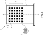
- Figure 1 shows a hydrogen burner 1 comprising a burner deck 2 with a plurality of holes 3 and an end-cap 4 at a distal end of the burner deck 2.
- the plurality of holes 3 are situated within a burner holes array 3b which is a grid-like structure comprising groups of holes 3 wherein the groups are aligned in horizontal rows and vertical columns. The rows are situated perpendicular to a burner axis A and the columns are situated parallel to the burner axis A.
- a last row 3a of the plurality of holes 3 can be seen within the dotted ellipse and a minimal distance Y being defined between said last row 3a and the end-cap 4.
- this minimal distance Y is between 2 to 10 mm and more preferably between 3 and 6 mm.
- a zoomed-in portion of the hydrogen burner 1 is shown as an aspect of the hydrogen burner 1a.
- the last row 3a of the holes is shown in close proximity of the end-cap 4.
- the grid-like structure comprising groups of holes 3 can be seen while more clearly identifying the individual holes 3.
- the distance Y can be seen between the last row 3a of the burner holes 3 and the end-cap 4. Again, this minimal distance Y is preferably between 2 to 10 mm and more preferably between 3 and 6 mm.
Landscapes
- Engineering & Computer Science (AREA)
- Chemical & Material Sciences (AREA)
- Combustion & Propulsion (AREA)
- Mechanical Engineering (AREA)
- General Engineering & Computer Science (AREA)
- Gas Burners (AREA)
- Feeding And Controlling Fuel (AREA)
Abstract
The present invention relates to a hydrogen burner comprising a burner deck having a plurality of holes, an end-cap located at a distal end of said burner deck, and a defined minimal distance between the last row of said holes and said end-cap, wherein said distance is configured to reduce the chances of flashback.
Description
- The present invention relates to a hydrogen burner comprising a burner deck having a plurality of holes, an end-cap located at a distal end of said burner deck, and a defined minimal distance between the last row of said holes and said end-cap, wherein said distance is configured to reduce the chances of flashback. The invention also relates to a gas boiler comprising such a hydrogen burner. The invention further relates to a method for reducing the risk of flashback by means of such a hydrogen burner.
- Hydrogen burners, devices that combine hydrogen gas with atmospheric oxygen to produce a flame, have been a focal point of research due to their potential as an environmentally friendly alternative to carbon-based fuels. Burners must be designed to ensure efficient combustion and safety. One of the paramount safety concerns in hydrogen combustion is 'flashback,' a potentially hazardous condition where the flame travels back into the combustion device, potentially causing explosions or damage to the equipment.
- Despite the advances on hydrogen burners, there remains a problem around flashback occurrences due to stagnated flow when burner holes are positioned too proximally to the endcap. Earlier solutions predominantly revolved around the perforation area of the burner deck as a primary determinant of flashback. However, the specific importance of the distance between the last row of holes and the endcap, in relation to flashback sensitivity, has not been emphasized in prior art.
- The object of the invention therefor is to reduce the risk of flashback by selecting a proper distance between the last row of burner holes to the endcap offering a safer and more efficient hydrogen burner design.
- The object of the invention is achieved by providing a hydrogen burner is provided comprising a burner deck having a plurality of holes, an end-cap located at a distal end of the burner deck; and a defined minimal distance between the last row of the holes and the end-cap, wherein the distance is configured to reduce the chances of flashback.
- By providing a hydrogen burner with a defined minimal distance between the last row of the holes and the end-cap, the risk of stagnation of flow within said distance can be reduced and as the risk of flashback is reduced. If the distance would be too small, and the last row of holes would thus be too close to the end-cap, the gas flow will be disturbed by either turbulence, pressure differences or a slow down of the flow which may contribute to the flashback behavior. Thus by having a certain minimal distance, the gasflow may be more even which, additionally, also contributes into a better cooling of the burner deck near the end-cap as the gas flow also has a cooling effect when flowing properly.
- In an embodiment, a hydrogen burner is provided wherein the distance is between 2-10mm. In this embodiment, the predefined minimum distance between the last row of holes and the end-cap falls within a range of 2-10mm. The use of this range minimizes the risk of flashback. It provides sufficient room to avoid stagnation, thereby ensuring smooth gas flow and reducing the chance of unintended flashback.
- In an embodiment, a hydrogen burner is provided wherein the distance is between 3-6mm. This preferred range helps in ensuring an even more reduced risk of flashback while optimizing the total perforation area of the burner deck.
- In an embodiment, a hydrogen burner is provided wherein the perforation range of the burner is greater than 0% and less than or equal to 5%. The perforation range of the burner deck is another factor of flashback. This embodiment establishes that the perforation (or the total area of the holes) on the burner deck should exceed 0% but not surpass 5%. Ensuring the perforation stays within this defined range further optimizes the performance of the burner and prevents flashback.
- In an embodiment, a hydrogen burner is provided wherein the perforation range of the burner is around 1.6%. This particular value has been identified as an ideal percentage to ensure efficient gas mixing and flow, reducing the risk of flashback significantly.
- In an embodiment, a hydrogen burner is provided further comprising a cone configured to decrease the volume of the burner. To further enhance the burner's efficiency and safety, this embodiment introduces a cone structure that decreases the burner's volume. This structure is beneficial for optimizing the flow dynamics within the burner, thus further minimizing the risk of flashback.
- In an embodiment, a hydrogen burner is provided wherein the gas composition for the burner is between 98-100% hydrogen. By ensuring the gas composition is between 98-100% hydrogen, the burner achieves optimal performance, offering a higher safety profile by reducing the chance of flashback.
- In an embodiment, a hydrogen burner is provided wherein the burner deck is fabricated through a punching process. The manufacturing process for the hydrogen burner deck involves a punching method. This fabrication technique allows for precise hole formations, ensuring consistency in the design and enhancing the burner's efficiency and safety.
- In an aspect of the invention, a gas boiler is provided comprising a hydrogen burner according to any of the previously disclosed embodiments.
- In another aspect of the invention, a method for reducing the risk of flashback in a hydrogen burner is provided comprising the steps of providing a burner deck having a plurality of holes, positioning an end-cap at a distal end of the burner deck, and setting a defined minimal distance between the last row of the holes and the end-cap. This embodiment outlines a method to design a hydrogen burner that minimizes the risk of flashback. By providing a burner deck with multiple holes, positioning an end-cap at its far end, and ensuring a set minimum distance between the end-cap and the last row of holes, this method ensures a systematic approach to achieving a safer burner design.
- In an embodiment, a method for reducing the risk of flashback in a hydrogen burner is provided wherein the step of setting a defined minimal distance includes setting the distance between 3-6mm. By setting the distance between 3-6mm, the method ensures that the burner remains within the most favorable range to prevent flashback, optimizing the burner's performance and safety.
- In an embodiment, a method for reducing the risk of flashback in a hydrogen burner is provided further comprising the step of setting the perforation range of the burner to be approximately 1.6%. By adjusting the burner deck's perforation range to be around 1.6%, the method ensures efficient gas mixing and flow, which further minimizes the risk of flashback.
- In an embodiment, a method for reducing the risk of flashback in a hydrogen burner is provided further comprising the step of introducing gas with a composition of 98-100% hydrogen into the burner. By introducing hydrogen gas with a composition ranging from 98-100% hydrogen into the burner, the method reaches an optimal, or at least near-optimal, performance and a higher safety profile.
- In the figures, the subject-matter of the invention is schematically shown, wherein identical or similarly acting elements are usually provided with the same reference signs.
- Fig. 1
- shows a schematic representation of a hydrogen burner according to an invention.
- Fig. 2
- shows a schematic representation of an aspect of the hydrogen burner according to the invention.
-
Figure 1 shows ahydrogen burner 1 comprising aburner deck 2 with a plurality ofholes 3 and an end-cap 4 at a distal end of theburner deck 2. The plurality ofholes 3 are situated within aburner holes array 3b which is a grid-like structure comprising groups ofholes 3 wherein the groups are aligned in horizontal rows and vertical columns. The rows are situated perpendicular to a burner axis A and the columns are situated parallel to the burner axis A. Furthermore, a last row 3a of the plurality ofholes 3 can be seen within the dotted ellipse and a minimal distance Y being defined between said last row 3a and the end-cap 4. Preferably, this minimal distance Y is between 2 to 10 mm and more preferably between 3 and 6 mm. - In
Figure 2 , a zoomed-in portion of thehydrogen burner 1 is shown as an aspect of thehydrogen burner 1a. The last row 3a of the holes is shown in close proximity of the end-cap 4. The grid-like structure comprising groups ofholes 3 can be seen while more clearly identifying theindividual holes 3. Also, the distance Y can be seen between the last row 3a of theburner holes 3 and the end-cap 4. Again, this minimal distance Y is preferably between 2 to 10 mm and more preferably between 3 and 6 mm. -
- 1
- hydrogen burner
- 1a
- aspect of the hydrogen burner
- 2
- burner deck
- 3
- burner holes
- 3a
- last row of burner holes
- 3b
- burner holes array
- 4
- end-cap
- A
- burner axis
- Y
- minimal distance
Claims (13)
- A hydrogen burner (1) comprising:- a burner deck (2) having a plurality of holes (3);- an end-cap (4) located at a distal end of said burner deck (2); and- a defined minimal distance (Y) between the last row (3a) of said holes (3) and said end-cap (4), wherein said distance is configured to reduce the chances of flashback.
- The hydrogen burner (1) of claim 1, wherein said distance (Y) is between 2-10mm.
- The hydrogen burner (1) of claim 2, wherein said distance (Y) is between 3-6mm.
- The hydrogen burner (1) of claim 1, wherein the perforation range of the burner (1) is greater than 0% and less than or equal to 5%.
- The hydrogen burner (1) of claim 4, wherein the perforation range of the burner (1) is around 1.6%.
- The hydrogen burner (1) of claim 1, further comprising a cone configured to decrease the volume of the burner (1).
- The hydrogen burner (1) of claim 1, wherein the gas composition for the burner (1) is between 98-100% hydrogen.
- The hydrogen burner (1) of claim 1, wherein the burner deck (2) is fabricated through a punching process.
- A gas boiler comprising a hydrogen burner (1) according to any of the previous claims.
- A method for reducing the risk of flashback in a hydrogen burner (1), comprising the steps of:- providing a burner deck (2) having a plurality of holes (3);- positioning an end-cap (4) at a distal end of the burner deck (2); and- setting a defined minimal distance (Y) between the last row (3a) of said holes and said end-cap (4).
- The method of claim 10, wherein the step of setting a defined minimal distance (Y) includes setting the distance (Y) between 3-6mm.
- The method of claim 10 or 11, further comprising the step of setting the perforation range of the burner to be approximately 1.6%.
- The method of any of claims 10 to 12, further comprising the step of introducing gas with a composition of 98-100% hydrogen into the burner.
Priority Applications (1)
| Application Number | Priority Date | Filing Date | Title |
|---|---|---|---|
| EP23204020.4A EP4542113A1 (en) | 2023-10-17 | 2023-10-17 | Hydrogen gas burner |
Applications Claiming Priority (1)
| Application Number | Priority Date | Filing Date | Title |
|---|---|---|---|
| EP23204020.4A EP4542113A1 (en) | 2023-10-17 | 2023-10-17 | Hydrogen gas burner |
Publications (1)
| Publication Number | Publication Date |
|---|---|
| EP4542113A1 true EP4542113A1 (en) | 2025-04-23 |
Family
ID=88417573
Family Applications (1)
| Application Number | Title | Priority Date | Filing Date |
|---|---|---|---|
| EP23204020.4A Withdrawn EP4542113A1 (en) | 2023-10-17 | 2023-10-17 | Hydrogen gas burner |
Country Status (1)
| Country | Link |
|---|---|
| EP (1) | EP4542113A1 (en) |
Citations (4)
| Publication number | Priority date | Publication date | Assignee | Title |
|---|---|---|---|---|
| WO2021140036A1 (en) * | 2020-01-08 | 2021-07-15 | Bekaert Combustion Technology B.V. | Gas burner and heating appliance |
| EP4123221A1 (en) * | 2021-07-22 | 2023-01-25 | BDR Thermea Group B.V. | Gas burner with a volume reducer |
| WO2023057937A1 (en) * | 2021-10-07 | 2023-04-13 | Polidoro S.P.A. | Pre-mixing burner |
| WO2023078949A1 (en) * | 2021-11-04 | 2023-05-11 | Bekaert Combustion Technology B.V. | Premix gas burner |
-
2023
- 2023-10-17 EP EP23204020.4A patent/EP4542113A1/en not_active Withdrawn
Patent Citations (4)
| Publication number | Priority date | Publication date | Assignee | Title |
|---|---|---|---|---|
| WO2021140036A1 (en) * | 2020-01-08 | 2021-07-15 | Bekaert Combustion Technology B.V. | Gas burner and heating appliance |
| EP4123221A1 (en) * | 2021-07-22 | 2023-01-25 | BDR Thermea Group B.V. | Gas burner with a volume reducer |
| WO2023057937A1 (en) * | 2021-10-07 | 2023-04-13 | Polidoro S.P.A. | Pre-mixing burner |
| WO2023078949A1 (en) * | 2021-11-04 | 2023-05-11 | Bekaert Combustion Technology B.V. | Premix gas burner |
Similar Documents
| Publication | Publication Date | Title |
|---|---|---|
| US10215403B2 (en) | Gas premix burner and gas water heater | |
| US10995965B2 (en) | Ultra-low NOx burner | |
| EP3067625B1 (en) | Gas turbine combustor, gas turbine and method | |
| CN113310049B (en) | Micro-scale premixing and grading burner | |
| JP2011510902A (en) | Low nitrogen oxide gas injector | |
| US8776524B2 (en) | Fuel distribution system for a gas turbine with multistage burner arrangement | |
| US8230687B2 (en) | Multi-tube arrangement for combustor and method of making the multi-tube arrangement | |
| CN114034043A (en) | Gas and air gas mixing structure and combustor | |
| CN107023834A (en) | A kind of nozzle and burner of multiple dimensioned flame on duty | |
| CN114151804B (en) | Exhaust gas treatment burners for power generation systems | |
| CN115013811A (en) | Ultra-low nitrogen combustion head for horizontally-mounted vertical combustion burner | |
| JP5558253B2 (en) | Hydrogen combustion equipment | |
| CN109654534A (en) | A kind of firing optimization method of DLN1.0 combustion system | |
| EP4163544A1 (en) | Burner deck and process of manufaturing thereof | |
| CN219607155U (en) | Calcination rotary kiln igniter | |
| JP3899082B2 (en) | Premixed fuel injection device | |
| CN119802595B (en) | A natural gas hydrogen-blended gas burner | |
| CN223550454U (en) | Burners and gas water heaters | |
| CN214619519U (en) | Sub-low NOxBurner with a burner head | |
| CN221150082U (en) | Fuel cell combustion device | |
| EP1346426A1 (en) | Improvements in and relating to fuel cells | |
| CN223896019U (en) | Multistage cyclone structure capable of reducing pollutant emission | |
| US12618554B2 (en) | Burner component and burner | |
| CN219243586U (en) | Combustion cylinder and full-premix surface type combustor | |
| CN113357630B (en) | A stove plate for use on a burner |
Legal Events
| Date | Code | Title | Description |
|---|---|---|---|
| PUAI | Public reference made under article 153(3) epc to a published international application that has entered the european phase |
Free format text: ORIGINAL CODE: 0009012 |
|
| STAA | Information on the status of an ep patent application or granted ep patent |
Free format text: STATUS: THE APPLICATION HAS BEEN PUBLISHED |
|
| AK | Designated contracting states |
Kind code of ref document: A1 Designated state(s): AL AT BE BG CH CY CZ DE DK EE ES FI FR GB GR HR HU IE IS IT LI LT LU LV MC ME MK MT NL NO PL PT RO RS SE SI SK SM TR |
|
| STAA | Information on the status of an ep patent application or granted ep patent |
Free format text: STATUS: THE APPLICATION IS DEEMED TO BE WITHDRAWN |
|
| 18D | Application deemed to be withdrawn |
Effective date: 20251024 |