EP4542080A1 - Endless belt and method for manufacturing endless belt - Google Patents
Endless belt and method for manufacturing endless belt Download PDFInfo
- Publication number
- EP4542080A1 EP4542080A1 EP23823954.5A EP23823954A EP4542080A1 EP 4542080 A1 EP4542080 A1 EP 4542080A1 EP 23823954 A EP23823954 A EP 23823954A EP 4542080 A1 EP4542080 A1 EP 4542080A1
- Authority
- EP
- European Patent Office
- Prior art keywords
- layer
- reinforcement sheet
- joint
- endless belt
- joint portion
- Prior art date
- Legal status (The legal status is an assumption and is not a legal conclusion. Google has not performed a legal analysis and makes no representation as to the accuracy of the status listed.)
- Pending
Links
Images



Classifications
-
- B—PERFORMING OPERATIONS; TRANSPORTING
- B29—WORKING OF PLASTICS; WORKING OF SUBSTANCES IN A PLASTIC STATE IN GENERAL
- B29D—PRODUCING PARTICULAR ARTICLES FROM PLASTICS OR FROM SUBSTANCES IN A PLASTIC STATE
- B29D29/00—Producing belts or bands
- B29D29/06—Conveyor belts
-
- B—PERFORMING OPERATIONS; TRANSPORTING
- B29—WORKING OF PLASTICS; WORKING OF SUBSTANCES IN A PLASTIC STATE IN GENERAL
- B29C—SHAPING OR JOINING OF PLASTICS; SHAPING OF MATERIAL IN A PLASTIC STATE, NOT OTHERWISE PROVIDED FOR; AFTER-TREATMENT OF THE SHAPED PRODUCTS, e.g. REPAIRING
- B29C65/00—Joining or sealing of preformed parts, e.g. welding of plastics materials; Apparatus therefor
- B29C65/02—Joining or sealing of preformed parts, e.g. welding of plastics materials; Apparatus therefor by heating, with or without pressure
-
- B—PERFORMING OPERATIONS; TRANSPORTING
- B29—WORKING OF PLASTICS; WORKING OF SUBSTANCES IN A PLASTIC STATE IN GENERAL
- B29C—SHAPING OR JOINING OF PLASTICS; SHAPING OF MATERIAL IN A PLASTIC STATE, NOT OTHERWISE PROVIDED FOR; AFTER-TREATMENT OF THE SHAPED PRODUCTS, e.g. REPAIRING
- B29C65/00—Joining or sealing of preformed parts, e.g. welding of plastics materials; Apparatus therefor
- B29C65/56—Joining or sealing of preformed parts, e.g. welding of plastics materials; Apparatus therefor using mechanical means or mechanical connections, e.g. form-fits
-
- B—PERFORMING OPERATIONS; TRANSPORTING
- B29—WORKING OF PLASTICS; WORKING OF SUBSTANCES IN A PLASTIC STATE IN GENERAL
- B29C—SHAPING OR JOINING OF PLASTICS; SHAPING OF MATERIAL IN A PLASTIC STATE, NOT OTHERWISE PROVIDED FOR; AFTER-TREATMENT OF THE SHAPED PRODUCTS, e.g. REPAIRING
- B29C65/00—Joining or sealing of preformed parts, e.g. welding of plastics materials; Apparatus therefor
- B29C65/72—Joining or sealing of preformed parts, e.g. welding of plastics materials; Apparatus therefor by combined operations or combined techniques, e.g. welding and stitching
-
- B—PERFORMING OPERATIONS; TRANSPORTING
- B29—WORKING OF PLASTICS; WORKING OF SUBSTANCES IN A PLASTIC STATE IN GENERAL
- B29C—SHAPING OR JOINING OF PLASTICS; SHAPING OF MATERIAL IN A PLASTIC STATE, NOT OTHERWISE PROVIDED FOR; AFTER-TREATMENT OF THE SHAPED PRODUCTS, e.g. REPAIRING
- B29C66/00—General aspects of processes or apparatus for joining preformed parts
- B29C66/01—General aspects dealing with the joint area or with the area to be joined
- B29C66/02—Preparation of the material, in the area to be joined, prior to joining or welding
- B29C66/022—Mechanical pre-treatments, e.g. reshaping
- B29C66/0224—Mechanical pre-treatments, e.g. reshaping with removal of material
- B29C66/02241—Cutting, e.g. by using waterjets, or sawing
-
- B—PERFORMING OPERATIONS; TRANSPORTING
- B29—WORKING OF PLASTICS; WORKING OF SUBSTANCES IN A PLASTIC STATE IN GENERAL
- B29C—SHAPING OR JOINING OF PLASTICS; SHAPING OF MATERIAL IN A PLASTIC STATE, NOT OTHERWISE PROVIDED FOR; AFTER-TREATMENT OF THE SHAPED PRODUCTS, e.g. REPAIRING
- B29C66/00—General aspects of processes or apparatus for joining preformed parts
- B29C66/01—General aspects dealing with the joint area or with the area to be joined
- B29C66/05—Particular design of joint configurations
- B29C66/10—Particular design of joint configurations particular design of the joint cross-sections
- B29C66/11—Joint cross-sections comprising a single joint-segment, i.e. one of the parts to be joined comprising a single joint-segment in the joint cross-section
- B29C66/114—Single butt joints
- B29C66/1142—Single butt to butt joints
-
- B—PERFORMING OPERATIONS; TRANSPORTING
- B29—WORKING OF PLASTICS; WORKING OF SUBSTANCES IN A PLASTIC STATE IN GENERAL
- B29C—SHAPING OR JOINING OF PLASTICS; SHAPING OF MATERIAL IN A PLASTIC STATE, NOT OTHERWISE PROVIDED FOR; AFTER-TREATMENT OF THE SHAPED PRODUCTS, e.g. REPAIRING
- B29C66/00—General aspects of processes or apparatus for joining preformed parts
- B29C66/01—General aspects dealing with the joint area or with the area to be joined
- B29C66/05—Particular design of joint configurations
- B29C66/20—Particular design of joint configurations particular design of the joint lines, e.g. of the weld lines
- B29C66/22—Particular design of joint configurations particular design of the joint lines, e.g. of the weld lines said joint lines being in the form of recurring patterns
- B29C66/223—Particular design of joint configurations particular design of the joint lines, e.g. of the weld lines said joint lines being in the form of recurring patterns being in the form of a triangle wave or of a sawtooth wave, e.g. zigzagged
-
- B—PERFORMING OPERATIONS; TRANSPORTING
- B29—WORKING OF PLASTICS; WORKING OF SUBSTANCES IN A PLASTIC STATE IN GENERAL
- B29C—SHAPING OR JOINING OF PLASTICS; SHAPING OF MATERIAL IN A PLASTIC STATE, NOT OTHERWISE PROVIDED FOR; AFTER-TREATMENT OF THE SHAPED PRODUCTS, e.g. REPAIRING
- B29C66/00—General aspects of processes or apparatus for joining preformed parts
- B29C66/01—General aspects dealing with the joint area or with the area to be joined
- B29C66/05—Particular design of joint configurations
- B29C66/303—Particular design of joint configurations the joint involving an anchoring effect
- B29C66/3034—Particular design of joint configurations the joint involving an anchoring effect making use of additional elements, e.g. meshes
- B29C66/30341—Particular design of joint configurations the joint involving an anchoring effect making use of additional elements, e.g. meshes non-integral with the parts to be joined, e.g. making use of extra elements
-
- B—PERFORMING OPERATIONS; TRANSPORTING
- B29—WORKING OF PLASTICS; WORKING OF SUBSTANCES IN A PLASTIC STATE IN GENERAL
- B29C—SHAPING OR JOINING OF PLASTICS; SHAPING OF MATERIAL IN A PLASTIC STATE, NOT OTHERWISE PROVIDED FOR; AFTER-TREATMENT OF THE SHAPED PRODUCTS, e.g. REPAIRING
- B29C66/00—General aspects of processes or apparatus for joining preformed parts
- B29C66/40—General aspects of joining substantially flat articles, e.g. plates, sheets or web-like materials; Making flat seams in tubular or hollow articles; Joining single elements to substantially flat surfaces
- B29C66/41—Joining substantially flat articles ; Making flat seams in tubular or hollow articles
- B29C66/43—Joining a relatively small portion of the surface of said articles
- B29C66/432—Joining a relatively small portion of the surface of said articles for making tubular articles or closed loops, e.g. by joining several sheets ; for making hollow articles or hollow preforms
- B29C66/4322—Joining a relatively small portion of the surface of said articles for making tubular articles or closed loops, e.g. by joining several sheets ; for making hollow articles or hollow preforms by joining a single sheet to itself
-
- B—PERFORMING OPERATIONS; TRANSPORTING
- B29—WORKING OF PLASTICS; WORKING OF SUBSTANCES IN A PLASTIC STATE IN GENERAL
- B29C—SHAPING OR JOINING OF PLASTICS; SHAPING OF MATERIAL IN A PLASTIC STATE, NOT OTHERWISE PROVIDED FOR; AFTER-TREATMENT OF THE SHAPED PRODUCTS, e.g. REPAIRING
- B29C66/00—General aspects of processes or apparatus for joining preformed parts
- B29C66/40—General aspects of joining substantially flat articles, e.g. plates, sheets or web-like materials; Making flat seams in tubular or hollow articles; Joining single elements to substantially flat surfaces
- B29C66/41—Joining substantially flat articles ; Making flat seams in tubular or hollow articles
- B29C66/43—Joining a relatively small portion of the surface of said articles
- B29C66/432—Joining a relatively small portion of the surface of said articles for making tubular articles or closed loops, e.g. by joining several sheets ; for making hollow articles or hollow preforms
- B29C66/4324—Joining a relatively small portion of the surface of said articles for making tubular articles or closed loops, e.g. by joining several sheets ; for making hollow articles or hollow preforms for making closed loops, e.g. belts
-
- B—PERFORMING OPERATIONS; TRANSPORTING
- B29—WORKING OF PLASTICS; WORKING OF SUBSTANCES IN A PLASTIC STATE IN GENERAL
- B29C—SHAPING OR JOINING OF PLASTICS; SHAPING OF MATERIAL IN A PLASTIC STATE, NOT OTHERWISE PROVIDED FOR; AFTER-TREATMENT OF THE SHAPED PRODUCTS, e.g. REPAIRING
- B29C66/00—General aspects of processes or apparatus for joining preformed parts
- B29C66/70—General aspects of processes or apparatus for joining preformed parts characterised by the composition, physical properties or the structure of the material of the parts to be joined; Joining with non-plastics material
- B29C66/71—General aspects of processes or apparatus for joining preformed parts characterised by the composition, physical properties or the structure of the material of the parts to be joined; Joining with non-plastics material characterised by the composition of the plastics material of the parts to be joined
-
- B—PERFORMING OPERATIONS; TRANSPORTING
- B29—WORKING OF PLASTICS; WORKING OF SUBSTANCES IN A PLASTIC STATE IN GENERAL
- B29C—SHAPING OR JOINING OF PLASTICS; SHAPING OF MATERIAL IN A PLASTIC STATE, NOT OTHERWISE PROVIDED FOR; AFTER-TREATMENT OF THE SHAPED PRODUCTS, e.g. REPAIRING
- B29C66/00—General aspects of processes or apparatus for joining preformed parts
- B29C66/70—General aspects of processes or apparatus for joining preformed parts characterised by the composition, physical properties or the structure of the material of the parts to be joined; Joining with non-plastics material
- B29C66/72—General aspects of processes or apparatus for joining preformed parts characterised by the composition, physical properties or the structure of the material of the parts to be joined; Joining with non-plastics material characterised by the structure of the material of the parts to be joined
- B29C66/723—General aspects of processes or apparatus for joining preformed parts characterised by the composition, physical properties or the structure of the material of the parts to be joined; Joining with non-plastics material characterised by the structure of the material of the parts to be joined being multi-layered
-
- B—PERFORMING OPERATIONS; TRANSPORTING
- B29—WORKING OF PLASTICS; WORKING OF SUBSTANCES IN A PLASTIC STATE IN GENERAL
- B29C—SHAPING OR JOINING OF PLASTICS; SHAPING OF MATERIAL IN A PLASTIC STATE, NOT OTHERWISE PROVIDED FOR; AFTER-TREATMENT OF THE SHAPED PRODUCTS, e.g. REPAIRING
- B29C66/00—General aspects of processes or apparatus for joining preformed parts
- B29C66/70—General aspects of processes or apparatus for joining preformed parts characterised by the composition, physical properties or the structure of the material of the parts to be joined; Joining with non-plastics material
- B29C66/73—General aspects of processes or apparatus for joining preformed parts characterised by the composition, physical properties or the structure of the material of the parts to be joined; Joining with non-plastics material characterised by the intensive physical properties of the material of the parts to be joined, by the optical properties of the material of the parts to be joined, by the extensive physical properties of the parts to be joined, by the state of the material of the parts to be joined or by the material of the parts to be joined being a thermoplastic or a thermoset
- B29C66/739—General aspects of processes or apparatus for joining preformed parts characterised by the composition, physical properties or the structure of the material of the parts to be joined; Joining with non-plastics material characterised by the intensive physical properties of the material of the parts to be joined, by the optical properties of the material of the parts to be joined, by the extensive physical properties of the parts to be joined, by the state of the material of the parts to be joined or by the material of the parts to be joined being a thermoplastic or a thermoset characterised by the material of the parts to be joined being a thermoplastic or a thermoset
- B29C66/7392—General aspects of processes or apparatus for joining preformed parts characterised by the composition, physical properties or the structure of the material of the parts to be joined; Joining with non-plastics material characterised by the intensive physical properties of the material of the parts to be joined, by the optical properties of the material of the parts to be joined, by the extensive physical properties of the parts to be joined, by the state of the material of the parts to be joined or by the material of the parts to be joined being a thermoplastic or a thermoset characterised by the material of the parts to be joined being a thermoplastic or a thermoset characterised by the material of at least one of the parts being a thermoplastic
- B29C66/73921—General aspects of processes or apparatus for joining preformed parts characterised by the composition, physical properties or the structure of the material of the parts to be joined; Joining with non-plastics material characterised by the intensive physical properties of the material of the parts to be joined, by the optical properties of the material of the parts to be joined, by the extensive physical properties of the parts to be joined, by the state of the material of the parts to be joined or by the material of the parts to be joined being a thermoplastic or a thermoset characterised by the material of the parts to be joined being a thermoplastic or a thermoset characterised by the material of at least one of the parts being a thermoplastic characterised by the materials of both parts being thermoplastics
-
- F—MECHANICAL ENGINEERING; LIGHTING; HEATING; WEAPONS; BLASTING
- F16—ENGINEERING ELEMENTS AND UNITS; GENERAL MEASURES FOR PRODUCING AND MAINTAINING EFFECTIVE FUNCTIONING OF MACHINES OR INSTALLATIONS; THERMAL INSULATION IN GENERAL
- F16G—BELTS, CABLES, OR ROPES, PREDOMINANTLY USED FOR DRIVING PURPOSES; CHAINS; FITTINGS PREDOMINANTLY USED THEREFOR
- F16G1/00—Driving-belts
- F16G1/06—Driving-belts made of rubber
- F16G1/08—Driving-belts made of rubber with reinforcement bonded by the rubber
- F16G1/10—Driving-belts made of rubber with reinforcement bonded by the rubber with textile reinforcement
-
- F—MECHANICAL ENGINEERING; LIGHTING; HEATING; WEAPONS; BLASTING
- F16—ENGINEERING ELEMENTS AND UNITS; GENERAL MEASURES FOR PRODUCING AND MAINTAINING EFFECTIVE FUNCTIONING OF MACHINES OR INSTALLATIONS; THERMAL INSULATION IN GENERAL
- F16G—BELTS, CABLES, OR ROPES, PREDOMINANTLY USED FOR DRIVING PURPOSES; CHAINS; FITTINGS PREDOMINANTLY USED THEREFOR
- F16G1/00—Driving-belts
- F16G1/14—Driving-belts made of plastics
- F16G1/16—Driving-belts made of plastics with reinforcement bonded by the plastic material
-
- F—MECHANICAL ENGINEERING; LIGHTING; HEATING; WEAPONS; BLASTING
- F16—ENGINEERING ELEMENTS AND UNITS; GENERAL MEASURES FOR PRODUCING AND MAINTAINING EFFECTIVE FUNCTIONING OF MACHINES OR INSTALLATIONS; THERMAL INSULATION IN GENERAL
- F16G—BELTS, CABLES, OR ROPES, PREDOMINANTLY USED FOR DRIVING PURPOSES; CHAINS; FITTINGS PREDOMINANTLY USED THEREFOR
- F16G3/00—Belt fastenings, e.g. for conveyor belts
- F16G3/10—Joining belts by sewing, sticking, vulcanising, or the like; Constructional adaptations of the belt ends for this purpose
Definitions
- the present invention relates to an endless belt and a method for manufacturing an endless belt.
- a belt-shaped belt having a core layer As an endless belt as a high-speed transmission belt, a belt-shaped belt having a core layer is generally used.
- the endless belt includes a joint portion in which both ends of the belt-shaped belt are integrally bonded using an adhesive or thermal bonding. Both ends of the belt-shaped belt have mutually complementary shapes, for example, finger shapes.
- the joint portion of the endless belt has a small tensile strength because the core layer is cut. Accordingly, there is a problem that the endless belt is likely to be broken with the joint portion as a starting point.
- Patent Literature 1 JP2021-102970A
- An endless belt includes: a belt-shaped core layer; an intermediate layer made of a thermoplastic resin and laminated on at least one surface of the core layer; a surface layer laminated on a surface of the intermediate layer; and a joint portion in which a first end portion and a second end portion having mutually complementary shapes are joined, in which a reinforcement sheet is embedded in the intermediate layer to span the joint portion, the reinforcement sheet has gaps penetrating in a thickness direction thereof and is made of a woven fabric woven with a plurality of yarns including at least a plurality of warps and a plurality of wefts spanning the plurality of warps, and the reinforcement sheet is disposed such that a tensile strength of the reinforcement sheet is larger in a width direction of the joint portion spanning a joint direction of the joint portion than in the joint direction of the joint portion.
- the strength in the width direction of the joint portion can be further improved without impairing the flexibility in the joint direction of the joint portion.
- the endless belt 10 is obtained by joining end portions of a belt-shaped core layer 12 at a joint portion 15, and includes the core layer 12, a first intermediate layer 14, a second intermediate layer 16, a first surface layer 18, and a second surface layer 20.
- a thickness of the endless belt 10 is usually 0.5 mm to 10.0 mm, and a width perpendicular to the joint direction of the joint portion 15 is usually 10 mm to 5000 mm.
- the core layer 12 is made of canvas using polyester fiber, nylon fiber, aramid fiber, or glass fiber as a raw material for a warp or a weft.
- the first surface layer 18 is laminated on a surface of the first intermediate layer 14, and the second surface layer 20 is laminated on a surface of the second intermediate layer 16.
- the first surface layer 18 and the second surface layer 20 function as a protective material for protecting the core layer 12, and are made of rubber, resin, canvas, or synthetic leather.
- examples of the rubber that can be used to form the first surface layer 18 and the second surface layer 20 include millable urethane, nitrile rubber (NBR), hydrogenated nitrile rubber (H-NBR), ethylene propylene diene rubber (EPDM), ethylene propylene rubber (EPM), or chlorosulfonated polyethylene.
- examples of the resin that can be used include polyurethane elastomer, polyamide elastomer, polyester elastomer, polyvinyl chloride elastomer, or polyolefin elastomer.
- examples of the canvas that can be used include, for example, canvas using fibers such as polyester fibers or nylon fibers.
- the second surface layer 20 and the first surface layer 18 may be made of the same material or may be made of different materials.
- the endless belt 10 includes the joint portion 15.
- the joint portion 15 is a finger joint.
- the joint portion 15 includes a first end portion 22 and a second end portion 24 in a joined state.
- the first end portion 22 includes a tip end of the belt-shaped belt (not illustrated) in the joint direction.
- the second end portion 24 includes a base end of the belt-shaped belt (not illustrated) in the joint direction.
- the endless belt 10 is formed in an endless shape by joining the first end portion 22 and the second end portion 24.
- the first end portion 22 and the second end portion 24 each have a plurality of mutually complementary concave portions 19 and convex portions 21.
- the concave portion 19 has an isosceles triangular shape and a rectangular triangular shape recessed inward in the joint direction of the endless belt 10.
- the convex portion 21 has an isosceles triangular shape protruding outward in the joint direction.
- the first end portion 22 and the second end portion 24 have a saw blade shape in which a plurality of concave portions 19 and convex portions 21 are formed.
- a length of the concave portion 19 and the convex portion 21 in the width direction is 5 mm to 30 mm
- a length of the concave portion 19 and the convex portion 21 in the joint direction is 5 mm to 250 mm.
- the reinforcement sheet 26 is made of a plain woven fabric in which warps 261 and wefts 262 are woven to cross each other alternately above and below in the thickness direction. In regions surrounded by the warps 261 and the wefts 262, a plurality of gaps 28 penetrating in the thickness direction (z-direction) of the reinforcement sheet 26 are formed.
- the warps 261 are disposed to extend along the joint direction (x-direction) of the joint portion 15.
- the wefts 262 are disposed to extend along the width direction (y-direction) of the joint portion 15 spanning the joint direction of the joint portion 15.
- the gaps 28 are formed in rectangular regions surrounded by the warps 261 running in parallel and the wefts 262 running in parallel.
- a square region in which the warps 261 and the wefts 262 have the same density is defined as the gap 28, and the gap 28 is formed at a position where the warp 261 and the weft 262 intersect.
- a diameter of the weft 262 may be the same as or different from that of the warp 261, and for example, aramid fiber, or glass fiber, which has a high tensile strength, is used for the weft 262, and the weft 262 is formed to have a tensile strength larger than that of the warp 261.
- the reinforcement sheet 26 is embedded in the first intermediate layer 14 such that the direction in which the warp 261 extends is disposed in the joint direction and the direction in which the weft 262 having a tensile strength larger than that of the warp 261 extends is disposed in the width direction to make the tensile strength in the width direction (y-direction) larger than the tensile strength in the joint direction (x-direction) of the joint portion 15.
- the warp 261 and the weft 262 may be a single yarn, or may be configured from a plurality of yarns such as a two-ply yarn.
- the first intermediate layer 14 includes a surface-layer-side intermediate portion 27 disposed on a first surface layer 18 side of the reinforcement sheet 26 and a core-layer-side intermediate portion 29 disposed on a core layer 12 side of the reinforcement sheet 26.
- the surface-layer-side intermediate portion 27 and the core-layer-side intermediate portion 29 are connected by the thermoplastic resin constituting the first intermediate layer 14 in the gap 28 of the reinforcement sheet 26. That is, the gap 28 of the reinforcement sheet 26 is filled with the thermoplastic resin of the first intermediate layer 14, and the reinforcement sheet 26 is integrated with the first intermediate layer 14.
- a ratio of the gap 28 per unit area is 35% or more and 70% or less as viewed in the thickness direction.
- the reinforcement sheet 26 has sufficient strength.
- the ratio of the gap 28 is 35% or more, the surface-layer-side intermediate portion 27 and the core-layer-side intermediate portion 29 are sufficiently integrated, and peeling of the first intermediate layer 14 and the reinforcement sheet 26 can be prevented.
- the reinforcement sheet 26 has a thickness of about 50% of a thickness of the first intermediate layer 14 in a state of being embedded in the first intermediate layer 14.
- the thickness of the reinforcement sheet 26 is significantly more than 50% of the thickness of the first intermediate layer 14, the flexibility of the reinforcement sheet 26 is impaired, and the reinforcement sheet 26 may fall off from the first intermediate layer 14 during driving of the endless belt 10.
- the thickness of the reinforcement sheet 26 is significantly less than 50% of the thickness of the first intermediate layer 14, an effect as a reinforcement material is impaired, and the strength of the endless belt 10 cannot be sufficiently improved.
- Fig. 4a illustrates the first end portion 22 as a representative.
- the cut portion 32 is formed parallel to the joint direction of the joint portion 15.
- a length of the cut portion 32 in the joint direction is longer than a length of the concave portion 19 and the convex portion 21 formed later in a longitudinal direction.
- the cut portion 32 is preferably formed at a center position in the thickness direction of the first intermediate layer 14.
- the first intermediate layer 14 after the cut portion 32 is formed is separated into the surface-layer-side intermediate portion 27 integrated with the first surface layer 18 and the core-layer-side intermediate portion 29 integrated with the core layer 12.
- a separation portion 33 including the first surface layer 18 and the surface-layer-side intermediate portion 27 is formed in the first end portion 22 after the cut portion 32 is formed.
- the separation portion 33 can be folded back in a direction in which the surface-layer-side intermediate portion 27 and the core-layer-side intermediate portion 29 are separated from each other.
- the direction in which the surface-layer-side intermediate portion 27 and the core-layer-side intermediate portion 29 are separated is a direction in which a tip end of the separation portion 33 is bent toward the surface of the first surface layer 18.
- the separation portion 33 is also formed in the second end portion 24 after the cut portion 32 is formed.
- the first end portion 22 and the second end portion 24 are processed by using a known tool to form the plurality of concave portions 19 and the plurality of convex portions 21, respectively.
- a range in the joint direction in which the concave portion 19 and the convex portion 21 are formed is narrower than a region in which the cut portion 32 is formed.
- the first surface layer 18 is oriented upward, and the first end portion 22 and the second end portion 24 are butted against each other by combining the concave portion 19 and the convex portion 21.
- the reinforcement sheet 26 is disposed on the core-layer-side intermediate portion 29 to span the boundary between the first end portion 22 and the second end portion 24 in a state in which the separation portion 33 is folded back.
- the reinforcement sheet 26 is disposed in the region in which the cut portions 32 are formed beyond the range in which the concave portions 19 and the convex portions 21 are formed.
- the reinforcement sheet 26 is disposed such that the direction in which the warp 261 extends is the joint direction of the joint portion 15, and the direction in which the weft 262 having a tensile strength larger than that of the warp 261 and disposed perpendicular to the warp 261 extends is the width direction of the joint portion 15.
- the reinforcement sheet 26 is covered with the separation portion 33, and the surface-layer-side intermediate portion 27 is brought into contact with the surface of the reinforcement sheet 26.
- the concave portions 19 and the convex portions 21 of the separation portions 33 are combined and butted against each other.
- the region in which the cut portion 32 is formed is thermally bonded while being pressurized in the thickness direction.
- the thermoplastic resin of the first intermediate layer 14 and the second intermediate layer 16 melts, and the tip ends of the first end portion 22 and the second end portion 24 are fused to each other.
- the molten thermoplastic resins in the surface-layer-side intermediate portion 27 and the core-layer-side intermediate portion 29 flow through the gap 28 of the reinforcement sheet 26 and are fused to each other through the gap 28.
- the thermoplastic resin is cooled and solidified, the first intermediate layer 14 and the second intermediate layer 16 are integrated with each other between the first end portion 22 and the second end portion 24.
- the surface-layer-side intermediate portion 27 and the core-layer-side intermediate portion 29 are integrated with each other via the gap 28 of the reinforcement sheet 26.
- the first intermediate layer 14 holds the reinforcement sheet 26 at a position spanning the boundary between the first end portion 22 and the second end portion 24. In this manner, the endless belt 10 in which the reinforcement sheet 26 is embedded in the first intermediate layer 14 can be obtained.
- the endless belt 10 can be wound around a driving pulley 30 such that the second surface layer 20 and a surface of the driving pulley 30 are in contact with each other so as to be used as a transmission belt or a conveyance belt. Since the surface-layer-side intermediate portion 27 and the core-layer-side intermediate portion 29 of the first intermediate layer 14 are integrated through the gap 28 of the reinforcement sheet 26, the first intermediate layer 14 is more firmly joined to the reinforcement sheet 26. Accordingly, the endless belt 10 can prevent peeling between the reinforcement sheet 26 and the first intermediate layer 14 and further improve the strength of the joint portion 15. When the ratio of the gap 28 per unit area as viewed in the thickness direction is 35% or more and 70% or less, the strength of the joint portion 15 can be more reliably improved.
- the reinforcement sheet 26 is made of a plain woven fabric woven with a plurality of warps 261 and a plurality of wefts 262 having a tensile strength larger than that of the warps 261 and spanning the warps 261. Accordingly, the tensile strengths of the reinforcement sheet 26 in the direction in which the warp 261 extends and the direction in which the weft 262 extends can be made different. Accordingly, in the endless belt 10, by arranging the direction in which the tensile strength of the reinforcement sheet 26 is large in the width direction of the joint portion 15, the tensile strength in the width direction of the joint portion 15 can be further improved without impairing the flexibility in the joint direction of the joint portion 15. In particular, by using polyester fiber, nylon fiber, cotton, or the like for the warp 261, the flexibility of the joint portion 15 of the endless belt 10 in the joint direction is not impaired.
- the present invention is not limited to the embodiment described above, and includes the following modifications.
- the first intermediate layer 14 and the first surface layer 18 illustrated in Fig. 1b are applied as an intermediate layer in which a reinforcement sheet is embedded to span a joint portion, and a surface layer laminated on a surface of the intermediate layer, whereas the present invention is not limited thereto, and the second intermediate layer 16 and the second surface layer 20 illustrated in Fig. 1b may also be applied.
- the reinforcement sheet 26 is applied in which the plurality of wefts 262 having a tensile strength larger than that of the warps 261 are disposed along the width direction (y-direction) perpendicularly spanning the joint direction (x-direction) of the joint portion 15 to make the tensile strength in the width direction larger than the tensile strength in the joint direction, whereas the present invention is not limited thereto.
- a reinforcement sheet may be applied in which the plurality of wefts 262 having a tensile strength larger than that of the warps 261 are disposed in a direction (y-direction) obliquely spanning the joint direction (x-direction) of the joint portion 15 at an acute angle or an obtuse angle to make the tensile strength in the width direction larger than the tensile strength in the joint direction.
- the warps 261 may not be disposed along the joint direction of the joint portion 15, and a reinforcement sheet may be applied in which the warps are disposed to be inclined at an acute angle from the joint direction to make the tensile strength in the width direction larger than the tensile strength in the joint direction.
- a reinforcement sheet made of a woven fabric woven with a plurality of yarns including at least a plurality of warps and a plurality of wefts spanning the warps the reinforcement sheet 26 made of a plain woven fabric woven with the plurality of warps 261 and the plurality of wefts 262 is applied, whereas the present invention is not limited thereto, and a reinforcement sheet made of a woven fabric woven with a plurality of yarns including a plurality of warps and a plurality of wefts in various weaving methods may be applied.
- a reinforcement sheet 40 may be made of a twill woven fabric.
- Warps 401 of the reinforcement sheet 40 are passed to span two wefts 402 on a lower surface and then span two wefts 402 on an upper surface, and this is repeated for a plurality of wefts 402 that are perpendicular to the warps 401.
- the twill woven reinforcement sheet 40 can be obtained by weaving the weft 402 in the same manner as the warp 401.
- the densities (numbers) of the warps 261 and the wefts 262 of the reinforcement sheet 26 are the same in the joint direction and the width direction, but the present invention is not limited thereto.
- the density of the wefts may be made larger than the density of the warps to further improve the tensile strength in the width direction of the joint portion, and further improve the flexibility in the joint direction.
- the reinforcement sheet 26 is woven such that the warps 261 and the wefts 262 are perpendicular to each other, but the present invention is not limited thereto.
- a reinforcement sheet in which wefts are woven to obliquely cross warps may be used.
- the specific structure, shape, and the like in the embodiment of the present invention may be other structures and the like as long as the object of the present invention can be achieved.
Landscapes
- Engineering & Computer Science (AREA)
- Mechanical Engineering (AREA)
- General Engineering & Computer Science (AREA)
- Textile Engineering (AREA)
- Belt Conveyors (AREA)
- Woven Fabrics (AREA)
Abstract
Provided are an endless belt and a method for manufacturing an endless belt capable of further improving the strength in a width direction of a joint portion of the endless belt without impairing the flexibility in a joint direction of the joint portion. The endless belt includes: a belt-shaped core layer 12; an intermediate layer 14 made of a thermoplastic resin and laminated on at least one surface of the core layer 12; a surface layer 18 laminated on a surface of the intermediate layer 14; and a joint portion in which a first end portion and a second end portion having mutually complementary shapes are joined, in which a reinforcement sheet 26 is embedded in the intermediate layer 14 to span the joint portion, the reinforcement sheet 26 has gaps 28 penetrating in a thickness direction thereof and is made of a woven fabric woven with a weft 262 having a tensile strength larger than that of a warp, and the reinforcement sheet 26 is disposed such that a tensile strength of the reinforcement sheet 26 is larger in a width direction of the joint portion than in the joint direction of the joint portion.
Description
- The present invention relates to an endless belt and a method for manufacturing an endless belt.
- As an endless belt as a high-speed transmission belt, a belt-shaped belt having a core layer is generally used. The endless belt includes a joint portion in which both ends of the belt-shaped belt are integrally bonded using an adhesive or thermal bonding. Both ends of the belt-shaped belt have mutually complementary shapes, for example, finger shapes. The joint portion of the endless belt has a small tensile strength because the core layer is cut. Accordingly, there is a problem that the endless belt is likely to be broken with the joint portion as a starting point.
- Therefore, in the related art, in an endless belt in which a core layer, an intermediate layer containing a thermoplastic resin, and a surface canvas layer are laminated, a technique is known in which a reinforcement sheet that has gaps penetrating in a thickness direction thereof and is made of a knitted fabric is embedded in the intermediate layer to span both ends of a joint portion (for example, see Patent Literature 1).
- According to the technique described in Patent Literature 1, when the reinforcement sheet is embedded in the intermediate layer by thermal bonding, a thermoplastic resin of the intermediate layer is filled in the gap portion. Accordingly, there is an effect that both ends of the joint portion of the endless belt can be firmly connected. Here, unless the reinforcement sheet has enough flexibility in a joint direction (belt longitudinal direction) of the joint portion, the endless belt cannot be driven smoothly following the rotation of a driving pulley.
- Patent Literature 1:
JP2021-102970A - However, when the flexibility in the joint direction of the reinforcement sheet is emphasized, there is a problem that the strength in a width direction (belt width direction) perpendicular to the joint direction of the joint portion cannot be sufficiently secured.
- An object of the present invention is to provide an endless belt and a method for manufacturing an endless belt capable of further improving the strength in a width direction of a joint portion of the endless belt without impairing the flexibility in a joint direction of the joint portion.
- An endless belt according to the present invention includes: a belt-shaped core layer; an intermediate layer made of a thermoplastic resin and laminated on at least one surface of the core layer; a surface layer laminated on a surface of the intermediate layer; and a joint portion in which a first end portion and a second end portion having mutually complementary shapes are joined, in which a reinforcement sheet is embedded in the intermediate layer to span the joint portion, the reinforcement sheet has gaps penetrating in a thickness direction thereof and is made of a woven fabric woven with a plurality of yarns including at least a plurality of warps and a plurality of wefts spanning the plurality of warps, and the reinforcement sheet is disposed such that a tensile strength of the reinforcement sheet is larger in a width direction of the joint portion spanning a joint direction of the joint portion than in the joint direction of the joint portion.
- Regarding a method for manufacturing an endless belt according to the present invention, the endless belt includes a belt-shaped core layer, an intermediate layer made of a thermoplastic resin and laminated on at least one surface of the core layer, a surface layer laminated on a surface of the intermediate layer, and a joint portion in which a first end portion and a second end portion having mutually complementary shapes are joined, the method includes: a step of cutting the intermediate layer at both end portions of the belt-shaped shape of the core layer to separate the intermediate layer into a core-layer-side intermediate portion and a surface-layer-side intermediate portion; a step of processing both end portions of the endless belt into mutually complementary shapes to form the first end portion and the second end portion; a step of disposing a reinforcement sheet, that has gaps penetrating in a thickness direction thereof and is made of a woven fabric woven with a plurality of warps and a plurality of wefts, on a surface of the core-layer-side intermediate portion to span the first end portion and the second end portion; and a step of covering the reinforcement sheet with the surface-layer-side intermediate portion and the surface layer, thermally bonding the surface-layer-side intermediate portion and the core-layer-side intermediate portion, and filling the gaps of the reinforcement sheet with a thermoplastic resin to embed the reinforcement sheet in the intermediate layer, in which in the step of disposing the reinforcement sheet, the reinforcement sheet is disposed such that a tensile strength of the reinforcement sheet is larger in a width direction of the joint portion spanning a joint direction of the joint portion than in the joint direction of the joint portion.
- According to the present invention, by arranging the direction in which the tensile strength of the reinforcement sheet is large in the width direction of the joint portion, the strength in the width direction of the joint portion can be further improved without impairing the flexibility in the joint direction of the joint portion.
-
-
Fig. 1a is a plan view of an endless belt according to an embodiment. -
Fig. 1b is a cross-sectional view taken along aline 1b-1b inFig. 1a . -
Fig. 2a is a plan view of a reinforcement sheet. -
Fig. 2b is a cross-sectional view of the reinforcement sheet according to the embodiment. -
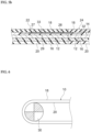
Fig. 3 is a partially enlarged cross-sectional view schematically illustrating a cross section of the endless belt according to the embodiment. -
Fig. 4a is a cross-sectional view illustrating a method for manufacturing the endless belt according to the embodiment in a stepwise manner, which indicates a state before cutting is performed. -
Fig. 4b is a cross-sectional view illustrating the method for manufacturing the endless belt according to the embodiment in a stepwise manner, which indicates a state after cutting is performed. -
Fig. 5a is a cross-sectional view illustrating the method for manufacturing the endless belt according to the embodiment in a stepwise manner, which indicates a state in which the reinforcement sheet is installed. -
Fig. 5b is a cross-sectional view illustrating the method for manufacturing the endless belt according to the embodiment in a stepwise manner, which indicates a state in which covering is performed with a separation portion. -
Fig. 6 is a schematic diagram illustrating a use state of the endless belt according to the embodiment. -
Fig. 7a is a plan view of a reinforcement sheet according to a modification of the embodiment. -
Fig. 7b is a cross-sectional view of the reinforcement sheet illustrated inFig. 7a . -
Fig. 8a is a plan view of a reinforcement sheet according to a modification of the embodiment. -
Fig. 8b is a cross-sectional view of the reinforcement sheet illustrated inFig. 8a . - Hereinafter, an embodiment of the present invention will be described in detail with reference to the drawings.
-
Figs. 1a and 1b each illustrate anendless belt 10 according to the present embodiment, in whichFig. 1a is a plan view of the endless belt, andFig. 1b is a cross-sectional view of theendless belt 10 in a thickness direction. In the following description, as illustrated inFigs. 1a and 1b , a belt longitudinal direction is referred to as a "joint direction" as an x-direction, a belt width direction perpendicularly spanning the belt longitudinal direction is referred to as a "width direction" as a y-direction, and a z-direction is referred to as a "thickness direction". - The
endless belt 10 is obtained by joining end portions of a belt-shaped core layer 12 at ajoint portion 15, and includes thecore layer 12, a firstintermediate layer 14, a secondintermediate layer 16, afirst surface layer 18, and asecond surface layer 20. A thickness of theendless belt 10 is usually 0.5 mm to 10.0 mm, and a width perpendicular to the joint direction of thejoint portion 15 is usually 10 mm to 5000 mm. - The
core layer 12 is made of canvas using polyester fiber, nylon fiber, aramid fiber, or glass fiber as a raw material for a warp or a weft. - The first
intermediate layer 14 is laminated on one surface of thecore layer 12, and the secondintermediate layer 16 is laminated on the other surface of thecore layer 12. The firstintermediate layer 14 and the secondintermediate layer 16 are made of a thermoplastic resin. Specifically, examples of the thermoplastic resin that can be used include polyurethane elastomer, polyamide elastomer, polyester elastomer, polyvinyl chloride elastomer, or polyolefin elastomer. - The
first surface layer 18 is laminated on a surface of the firstintermediate layer 14, and thesecond surface layer 20 is laminated on a surface of the secondintermediate layer 16. Thefirst surface layer 18 and thesecond surface layer 20 function as a protective material for protecting thecore layer 12, and are made of rubber, resin, canvas, or synthetic leather. - Specifically, examples of the rubber that can be used to form the
first surface layer 18 and thesecond surface layer 20 include millable urethane, nitrile rubber (NBR), hydrogenated nitrile rubber (H-NBR), ethylene propylene diene rubber (EPDM), ethylene propylene rubber (EPM), or chlorosulfonated polyethylene. Examples of the resin that can be used include polyurethane elastomer, polyamide elastomer, polyester elastomer, polyvinyl chloride elastomer, or polyolefin elastomer. Examples of the canvas that can be used include, for example, canvas using fibers such as polyester fibers or nylon fibers. Thesecond surface layer 20 and thefirst surface layer 18 may be made of the same material or may be made of different materials. - The
endless belt 10 includes thejoint portion 15. Thejoint portion 15 is a finger joint. Thejoint portion 15 includes afirst end portion 22 and asecond end portion 24 in a joined state. Thefirst end portion 22 includes a tip end of the belt-shaped belt (not illustrated) in the joint direction. Thesecond end portion 24 includes a base end of the belt-shaped belt (not illustrated) in the joint direction. Theendless belt 10 is formed in an endless shape by joining thefirst end portion 22 and thesecond end portion 24. - The
first end portion 22 and thesecond end portion 24 each have a plurality of mutually complementaryconcave portions 19 andconvex portions 21. Theconcave portion 19 has an isosceles triangular shape and a rectangular triangular shape recessed inward in the joint direction of theendless belt 10. Theconvex portion 21 has an isosceles triangular shape protruding outward in the joint direction. Thefirst end portion 22 and thesecond end portion 24 have a saw blade shape in which a plurality ofconcave portions 19 andconvex portions 21 are formed. A length of theconcave portion 19 and theconvex portion 21 in the width direction is 5 mm to 30 mm, and a length of theconcave portion 19 and theconvex portion 21 in the joint direction is 5 mm to 250 mm. - The first
intermediate layer 14 of theendless belt 10 includes areinforcement sheet 26 at a position spanning a boundary between thefirst end portion 22 and thesecond end portion 24. Thereinforcement sheet 26 is disposed in a region wider than a range from abase end 23 of theconcave portion 19 of thefirst end portion 22 to abase end 25 of theconcave portion 19 of thesecond end portion 24. A length of thereinforcement sheet 26 in the width direction is about - 1 mm to + 0 mm with respect to the length of theendless belt 10 in the width direction. A length of thereinforcement sheet 26 in the joint direction is larger than the length of theconcave portion 19 or theconvex portion 21 in the joint direction by about 20 mm and larger than a length of thejoint portion 15 by about 30 mm. - As illustrated in
Figs. 2a and 2b , thereinforcement sheet 26 is made of a plain woven fabric in which warps 261 andwefts 262 are woven to cross each other alternately above and below in the thickness direction. In regions surrounded by thewarps 261 and thewefts 262, a plurality ofgaps 28 penetrating in the thickness direction (z-direction) of thereinforcement sheet 26 are formed. Thewarps 261 are disposed to extend along the joint direction (x-direction) of thejoint portion 15. Thewefts 262 are disposed to extend along the width direction (y-direction) of thejoint portion 15 spanning the joint direction of thejoint portion 15. Thegaps 28 are formed in rectangular regions surrounded by thewarps 261 running in parallel and thewefts 262 running in parallel. In the present embodiment, a square region in which thewarps 261 and thewefts 262 have the same density is defined as thegap 28, and thegap 28 is formed at a position where thewarp 261 and theweft 262 intersect. - As the
warp 261, polyester fiber, nylon fiber, cotton, or the like having good flexibility is used. A diameter of theweft 262 may be the same as or different from that of thewarp 261, and for example, aramid fiber, or glass fiber, which has a high tensile strength, is used for theweft 262, and theweft 262 is formed to have a tensile strength larger than that of thewarp 261. Therefore, thereinforcement sheet 26 is embedded in the firstintermediate layer 14 such that the direction in which thewarp 261 extends is disposed in the joint direction and the direction in which theweft 262 having a tensile strength larger than that of thewarp 261 extends is disposed in the width direction to make the tensile strength in the width direction (y-direction) larger than the tensile strength in the joint direction (x-direction) of thejoint portion 15. Thewarp 261 and theweft 262 may be a single yarn, or may be configured from a plurality of yarns such as a two-ply yarn. - As illustrated in
Fig. 3 , the firstintermediate layer 14 includes a surface-layer-sideintermediate portion 27 disposed on afirst surface layer 18 side of thereinforcement sheet 26 and a core-layer-sideintermediate portion 29 disposed on acore layer 12 side of thereinforcement sheet 26. The surface-layer-sideintermediate portion 27 and the core-layer-sideintermediate portion 29 are connected by the thermoplastic resin constituting the firstintermediate layer 14 in thegap 28 of thereinforcement sheet 26. That is, thegap 28 of thereinforcement sheet 26 is filled with the thermoplastic resin of the firstintermediate layer 14, and thereinforcement sheet 26 is integrated with the firstintermediate layer 14. - In the
reinforcement sheet 26, a ratio of thegap 28 per unit area is 35% or more and 70% or less as viewed in the thickness direction. When the ratio of thegap 28 is 70% or less, thereinforcement sheet 26 has sufficient strength. When the ratio of thegap 28 is 35% or more, the surface-layer-sideintermediate portion 27 and the core-layer-sideintermediate portion 29 are sufficiently integrated, and peeling of the firstintermediate layer 14 and thereinforcement sheet 26 can be prevented. - The
reinforcement sheet 26 has a thickness of about 50% of a thickness of the firstintermediate layer 14 in a state of being embedded in the firstintermediate layer 14. When the thickness of thereinforcement sheet 26 is significantly more than 50% of the thickness of the firstintermediate layer 14, the flexibility of thereinforcement sheet 26 is impaired, and thereinforcement sheet 26 may fall off from the firstintermediate layer 14 during driving of theendless belt 10. When the thickness of thereinforcement sheet 26 is significantly less than 50% of the thickness of the firstintermediate layer 14, an effect as a reinforcement material is impaired, and the strength of theendless belt 10 cannot be sufficiently improved. - Next, a method for manufacturing the
endless belt 10 will be described. As illustrated inFig. 4a , in the firstintermediate layer 14 of each of thefirst end portion 22 and thesecond end portion 24 before joining, cutting is performed from respective tip ends in the joint direction to form cutportions 32.Fig. 4a illustrates thefirst end portion 22 as a representative. Thecut portion 32 is formed parallel to the joint direction of thejoint portion 15. A length of thecut portion 32 in the joint direction is longer than a length of theconcave portion 19 and theconvex portion 21 formed later in a longitudinal direction. Thecut portion 32 is preferably formed at a center position in the thickness direction of the firstintermediate layer 14. The firstintermediate layer 14 after thecut portion 32 is formed is separated into the surface-layer-sideintermediate portion 27 integrated with thefirst surface layer 18 and the core-layer-sideintermediate portion 29 integrated with thecore layer 12. - As illustrated in
Fig. 4b , aseparation portion 33 including thefirst surface layer 18 and the surface-layer-sideintermediate portion 27 is formed in thefirst end portion 22 after thecut portion 32 is formed. Theseparation portion 33 can be folded back in a direction in which the surface-layer-sideintermediate portion 27 and the core-layer-sideintermediate portion 29 are separated from each other. The direction in which the surface-layer-sideintermediate portion 27 and the core-layer-sideintermediate portion 29 are separated is a direction in which a tip end of theseparation portion 33 is bent toward the surface of thefirst surface layer 18. Although not illustrated, theseparation portion 33 is also formed in thesecond end portion 24 after thecut portion 32 is formed. - The
first end portion 22 and thesecond end portion 24 are processed by using a known tool to form the plurality ofconcave portions 19 and the plurality ofconvex portions 21, respectively. A range in the joint direction in which theconcave portion 19 and theconvex portion 21 are formed is narrower than a region in which thecut portion 32 is formed. Thefirst surface layer 18 is oriented upward, and thefirst end portion 22 and thesecond end portion 24 are butted against each other by combining theconcave portion 19 and theconvex portion 21. - As illustrated in
Fig. 5a , thereinforcement sheet 26 is disposed on the core-layer-sideintermediate portion 29 to span the boundary between thefirst end portion 22 and thesecond end portion 24 in a state in which theseparation portion 33 is folded back. Thereinforcement sheet 26 is disposed in the region in which thecut portions 32 are formed beyond the range in which theconcave portions 19 and theconvex portions 21 are formed. Thereinforcement sheet 26 is disposed such that the direction in which thewarp 261 extends is the joint direction of thejoint portion 15, and the direction in which theweft 262 having a tensile strength larger than that of thewarp 261 and disposed perpendicular to thewarp 261 extends is the width direction of thejoint portion 15. - As illustrated in
Fig. 5b , thereinforcement sheet 26 is covered with theseparation portion 33, and the surface-layer-sideintermediate portion 27 is brought into contact with the surface of thereinforcement sheet 26. Theconcave portions 19 and theconvex portions 21 of theseparation portions 33 are combined and butted against each other. In this state, around thefirst end portion 22 and thesecond end portion 24, at least the region in which thecut portion 32 is formed is thermally bonded while being pressurized in the thickness direction. By heating, the thermoplastic resin of the firstintermediate layer 14 and the secondintermediate layer 16 melts, and the tip ends of thefirst end portion 22 and thesecond end portion 24 are fused to each other. - In the first
intermediate layer 14, the molten thermoplastic resins in the surface-layer-sideintermediate portion 27 and the core-layer-sideintermediate portion 29 flow through thegap 28 of thereinforcement sheet 26 and are fused to each other through thegap 28. When the thermoplastic resin is cooled and solidified, the firstintermediate layer 14 and the secondintermediate layer 16 are integrated with each other between thefirst end portion 22 and thesecond end portion 24. - The surface-layer-side
intermediate portion 27 and the core-layer-sideintermediate portion 29 are integrated with each other via thegap 28 of thereinforcement sheet 26. As a result, the firstintermediate layer 14 holds thereinforcement sheet 26 at a position spanning the boundary between thefirst end portion 22 and thesecond end portion 24. In this manner, theendless belt 10 in which thereinforcement sheet 26 is embedded in the firstintermediate layer 14 can be obtained. - As illustrated in
Fig. 6 , theendless belt 10 can be wound around a drivingpulley 30 such that thesecond surface layer 20 and a surface of the drivingpulley 30 are in contact with each other so as to be used as a transmission belt or a conveyance belt. Since the surface-layer-sideintermediate portion 27 and the core-layer-sideintermediate portion 29 of the firstintermediate layer 14 are integrated through thegap 28 of thereinforcement sheet 26, the firstintermediate layer 14 is more firmly joined to thereinforcement sheet 26. Accordingly, theendless belt 10 can prevent peeling between thereinforcement sheet 26 and the firstintermediate layer 14 and further improve the strength of thejoint portion 15. When the ratio of thegap 28 per unit area as viewed in the thickness direction is 35% or more and 70% or less, the strength of thejoint portion 15 can be more reliably improved. - In addition, the
reinforcement sheet 26 according to the present embodiment is made of a plain woven fabric woven with a plurality ofwarps 261 and a plurality ofwefts 262 having a tensile strength larger than that of thewarps 261 and spanning thewarps 261. Accordingly, the tensile strengths of thereinforcement sheet 26 in the direction in which thewarp 261 extends and the direction in which theweft 262 extends can be made different. Accordingly, in theendless belt 10, by arranging the direction in which the tensile strength of thereinforcement sheet 26 is large in the width direction of thejoint portion 15, the tensile strength in the width direction of thejoint portion 15 can be further improved without impairing the flexibility in the joint direction of thejoint portion 15. In particular, by using polyester fiber, nylon fiber, cotton, or the like for thewarp 261, the flexibility of thejoint portion 15 of theendless belt 10 in the joint direction is not impaired. - The present invention is not limited to the embodiment described above, and includes the following modifications. In the embodiment described above, the first
intermediate layer 14 and thefirst surface layer 18 illustrated inFig. 1b are applied as an intermediate layer in which a reinforcement sheet is embedded to span a joint portion, and a surface layer laminated on a surface of the intermediate layer, whereas the present invention is not limited thereto, and the secondintermediate layer 16 and thesecond surface layer 20 illustrated inFig. 1b may also be applied. - In addition, in the embodiment described above, as a reinforcement sheet in which a plurality of wefts having a tensile strength larger than that of warps are disposed in a direction spanning a joint direction of a joint portion to make the tensile strength in a width direction larger than the tensile strength in the joint direction, the
reinforcement sheet 26 is applied in which the plurality ofwefts 262 having a tensile strength larger than that of thewarps 261 are disposed along the width direction (y-direction) perpendicularly spanning the joint direction (x-direction) of thejoint portion 15 to make the tensile strength in the width direction larger than the tensile strength in the joint direction, whereas the present invention is not limited thereto. As another embodiment, for example, a reinforcement sheet may be applied in which the plurality ofwefts 262 having a tensile strength larger than that of thewarps 261 are disposed in a direction (y-direction) obliquely spanning the joint direction (x-direction) of thejoint portion 15 at an acute angle or an obtuse angle to make the tensile strength in the width direction larger than the tensile strength in the joint direction. As another reinforcement sheet, thewarps 261 may not be disposed along the joint direction of thejoint portion 15, and a reinforcement sheet may be applied in which the warps are disposed to be inclined at an acute angle from the joint direction to make the tensile strength in the width direction larger than the tensile strength in the joint direction. - In the embodiment described above, as a reinforcement sheet made of a woven fabric woven with a plurality of yarns including at least a plurality of warps and a plurality of wefts spanning the warps, the
reinforcement sheet 26 made of a plain woven fabric woven with the plurality ofwarps 261 and the plurality ofwefts 262 is applied, whereas the present invention is not limited thereto, and a reinforcement sheet made of a woven fabric woven with a plurality of yarns including a plurality of warps and a plurality of wefts in various weaving methods may be applied. For example, as illustrated inFigs. 7a and 7b , areinforcement sheet 40 may be made of a twill woven fabric.Warps 401 of thereinforcement sheet 40 are passed to span twowefts 402 on a lower surface and then span twowefts 402 on an upper surface, and this is repeated for a plurality ofwefts 402 that are perpendicular to thewarps 401. The twill wovenreinforcement sheet 40 can be obtained by weaving theweft 402 in the same manner as thewarp 401. - Further, as illustrated in
Figs. 8a and 8b , areinforcement sheet 42 may be made of a satin woven fabric.Warps 421 of thereinforcement sheet 42 are passed to span fourwefts 422 on an upper surface and then span oneweft 422 on a lower surface, and this is repeated for a plurality ofwefts 422 that are perpendicular to thewarps 421. The satin wovenreinforcement sheet 42 can be obtained by weaving theweft 422 in the same manner as thewarp 421. - Even with
such reinforcement sheets reinforcement sheets wefts warps - In the embodiment described above, the densities (numbers) of the
warps 261 and thewefts 262 of thereinforcement sheet 26 are the same in the joint direction and the width direction, but the present invention is not limited thereto. For example, the density of the wefts may be made larger than the density of the warps to further improve the tensile strength in the width direction of the joint portion, and further improve the flexibility in the joint direction. In such a configuration, even if the tensile strengths of thewarp 261 and theweft 262 are the same, by making the density of the weft larger than the density of the warp, it is possible to realize a reinforcement sheet in which the tensile strength in the width direction is made larger than the tensile strength in the joint direction, and it is possible to achieve the same effect as the embodiment described above. - In the embodiment described above, the
warp 261 and theweft 262 of thereinforcement sheet 26 have the same diameter, but the present invention is not limited thereto. For example, a woven fabric in which the diameter of theweft 262 is made larger than the diameter of thewarp 261 may be used as the reinforcement sheet. In such a configuration, even if thewarp 261 and theweft 262 are made of the same yarn material, by making the diameter of the weft larger than the diameter of the warp, it is possible to realize a reinforcement sheet in which the tensile strength in the width direction is made larger than the tensile strength in the joint direction, and it is possible to achieve the same effect as the embodiment described above. - In the embodiment described above, the
reinforcement sheet 26 is woven such that thewarps 261 and thewefts 262 are perpendicular to each other, but the present invention is not limited thereto. For example, a reinforcement sheet in which wefts are woven to obliquely cross warps may be used. In addition, the specific structure, shape, and the like in the embodiment of the present invention may be other structures and the like as long as the object of the present invention can be achieved. -
- 10
- endless belt
- 12
- core layer
- 14
- first intermediate layer (intermediate layer)
- 15
- joint portion
- 18
- first surface layer (surface layer)
- 19
- concave portion
- 20
- second surface layer
- 21
- convex portion
- 26, 40, 42
- reinforcement sheet
- 27
- surface-layer-side intermediate portion
- 28
- gap
- 29
- core-layer-side intermediate portion
- 32
- cut portion
- 261, 401, 421
- warp
- 262, 402, 422
- weft
Claims (4)
- An endless belt comprising:a belt-shaped core layer;an intermediate layer made of a thermoplastic resin and laminated on at least one surface of the core layer;a surface layer laminated on a surface of the intermediate layer; anda joint portion in which a first end portion and a second end portion having mutually complementary shapes are joined, whereina reinforcement sheet is embedded in the intermediate layer to span the joint portion,the reinforcement sheet has gaps penetrating in a thickness direction thereof and is made of a woven fabric woven with a plurality of yarns including at least a plurality of warps and a plurality of wefts spanning the plurality of warps, andthe reinforcement sheet is disposed such that a tensile strength of the reinforcement sheet is larger in a width direction of the joint portion spanning a joint direction of the joint portion than in the joint direction of the joint portion.
- The endless belt according to claim 1, wherein
in the reinforcement sheet, the wefts having a tensile strength larger than that of the warps are disposed in a direction spanning the joint direction of the joint portion. - The endless belt according to claim 1 or 2, wherein
in the reinforcement sheet, the plurality of warps are disposed in the joint direction of the joint portion, and the plurality of wefts having a tensile strength larger than that of the warps are disposed in the width direction of the joint portion. - A method for manufacturing an endless belt, the endless belt includinga belt-shaped core layer,an intermediate layer made of a thermoplastic resin and laminated on at least one surface of the core layer,a surface layer laminated on a surface of the intermediate layer, anda joint portion in which a first end portion and a second end portion having mutually complementary shapes are joined, the method comprising:a step of cutting the intermediate layer at both end portions of the belt-shaped shape of the core layer to separate the intermediate layer into a core-layer-side intermediate portion and a surface-layer-side intermediate portion;a step of processing both end portions of the endless belt into mutually complementary shapes to form the first end portion and the second end portion;a step of disposing a reinforcement sheet, that has gaps penetrating in a thickness direction thereof and is made of a woven fabric woven with a plurality of warps and a plurality of wefts, on a surface of the core-layer-side intermediate portion to span the first end portion and the second end portion; anda step of covering the reinforcement sheet with the surface-layer-side intermediate portion and the surface layer, thermally bonding the surface-layer-side intermediate portion and the core-layer-side intermediate portion, and filling the gaps of the reinforcement sheet with a thermoplastic resin to embed the reinforcement sheet in the intermediate layer, whereinin the step of disposing the reinforcement sheet, the reinforcement sheet is disposed such that a tensile strength of the reinforcement sheet is larger in a width direction of the joint portion spanning a joint direction of the joint portion than in the joint direction of the joint portion.
Applications Claiming Priority (2)
| Application Number | Priority Date | Filing Date | Title |
|---|---|---|---|
| JP2022096123A JP7857167B2 (en) | 2022-06-14 | 2022-06-14 | Endless belt and method for manufacturing an endless belt |
| PCT/JP2023/022101 WO2023243664A1 (en) | 2022-06-14 | 2023-06-14 | Endless belt and method for manufacturing endless belt |
Publications (1)
| Publication Number | Publication Date |
|---|---|
| EP4542080A1 true EP4542080A1 (en) | 2025-04-23 |
Family
ID=89191387
Family Applications (1)
| Application Number | Title | Priority Date | Filing Date |
|---|---|---|---|
| EP23823954.5A Pending EP4542080A1 (en) | 2022-06-14 | 2023-06-14 | Endless belt and method for manufacturing endless belt |
Country Status (4)
| Country | Link |
|---|---|
| EP (1) | EP4542080A1 (en) |
| JP (1) | JP7857167B2 (en) |
| CN (1) | CN119365703A (en) |
| WO (1) | WO2023243664A1 (en) |
Family Cites Families (2)
| Publication number | Priority date | Publication date | Assignee | Title |
|---|---|---|---|---|
| JP2006144826A (en) * | 2004-11-16 | 2006-06-08 | Honda Motor Co Ltd | Timing belt |
| JP7446105B2 (en) * | 2019-12-24 | 2024-03-08 | ニッタ株式会社 | Endless belt and endless belt manufacturing method |
-
2022
- 2022-06-14 JP JP2022096123A patent/JP7857167B2/en active Active
-
2023
- 2023-06-14 EP EP23823954.5A patent/EP4542080A1/en active Pending
- 2023-06-14 WO PCT/JP2023/022101 patent/WO2023243664A1/en not_active Ceased
- 2023-06-14 CN CN202380046533.0A patent/CN119365703A/en active Pending
Also Published As
| Publication number | Publication date |
|---|---|
| JP2023182482A (en) | 2023-12-26 |
| WO2023243664A1 (en) | 2023-12-21 |
| CN119365703A (en) | 2025-01-24 |
| JP7857167B2 (en) | 2026-05-12 |
Similar Documents
| Publication | Publication Date | Title |
|---|---|---|
| US3783704A (en) | Power transmission, conveyor and vehicle track | |
| EP0716035B1 (en) | A belt construction having a mock leno fabric as an impact breaker or splice insert | |
| CN102405316A (en) | Seam for an industrial fabric and seaming element therefor | |
| EP1925576B1 (en) | Reinforced belt for powerturn applications | |
| JP2007511710A (en) | Joint structure for vertically long body | |
| US4299587A (en) | V-Belt | |
| WO2008022034A2 (en) | Laterally flexible reinforced structure | |
| EP0732225A2 (en) | Reinforcement fabric ply and composite | |
| CA1255107A (en) | Abrasive belt with a joint extending transversely to its longitudinal direction | |
| KR20090042882A (en) | Fiber cord for reinforcement with excellent adhesive strength and manufacturing method thereof | |
| US5275858A (en) | Woven conveyor belt splice fabric and conveyor belt splice formed therewith | |
| JP7446105B2 (en) | Endless belt and endless belt manufacturing method | |
| EP1295815B1 (en) | Conveyer belt with a reinforcing band | |
| JP7857167B2 (en) | Endless belt and method for manufacturing an endless belt | |
| US5558207A (en) | Belting having sealed edge and method of manufacture | |
| US20160237602A1 (en) | Weft-inserted warp knit fabric | |
| JPH02258881A (en) | Heat-bonding tape and its manufacture | |
| CN121399397A (en) | Reinforced belt joint | |
| JPH1077543A (en) | Welding fabric | |
| JP2018131707A (en) | Felt base fabric for papermaking and method for producing the same | |
| US20050245340A1 (en) | Power transmission belt and method of making same | |
| EP0950738B1 (en) | A fabric for welding | |
| JP3015844B2 (en) | Textile with floating band for connection | |
| JP2004036007A (en) | Joint part of dryer canvas for papermaking having reinforced selvedge part | |
| JP3909261B2 (en) | Joints of paper dryer dryer canvas with reinforced ears |
Legal Events
| Date | Code | Title | Description |
|---|---|---|---|
| STAA | Information on the status of an ep patent application or granted ep patent |
Free format text: STATUS: THE INTERNATIONAL PUBLICATION HAS BEEN MADE |
|
| PUAI | Public reference made under article 153(3) epc to a published international application that has entered the european phase |
Free format text: ORIGINAL CODE: 0009012 |
|
| STAA | Information on the status of an ep patent application or granted ep patent |
Free format text: STATUS: REQUEST FOR EXAMINATION WAS MADE |
|
| 17P | Request for examination filed |
Effective date: 20250114 |
|
| AK | Designated contracting states |
Kind code of ref document: A1 Designated state(s): AL AT BE BG CH CY CZ DE DK EE ES FI FR GB GR HR HU IE IS IT LI LT LU LV MC ME MK MT NL NO PL PT RO RS SE SI SK SM TR |
|
| DAV | Request for validation of the european patent (deleted) | ||
| DAX | Request for extension of the european patent (deleted) |