EP4542063A1 - Dispositif de fixation démontable de type aveugle, assemblage comportant au moins un tel dispositif de fixation et procédé de démontage d'un tel dispositif de fixation - Google Patents
Dispositif de fixation démontable de type aveugle, assemblage comportant au moins un tel dispositif de fixation et procédé de démontage d'un tel dispositif de fixation Download PDFInfo
- Publication number
- EP4542063A1 EP4542063A1 EP24205128.2A EP24205128A EP4542063A1 EP 4542063 A1 EP4542063 A1 EP 4542063A1 EP 24205128 A EP24205128 A EP 24205128A EP 4542063 A1 EP4542063 A1 EP 4542063A1
- Authority
- EP
- European Patent Office
- Prior art keywords
- expanding nut
- screw
- tool
- tubular body
- section
- Prior art date
- Legal status (The legal status is an assumption and is not a legal conclusion. Google has not performed a legal analysis and makes no representation as to the accuracy of the status listed.)
- Granted
Links
Images


Classifications
-
- F—MECHANICAL ENGINEERING; LIGHTING; HEATING; WEAPONS; BLASTING
- F16—ENGINEERING ELEMENTS AND UNITS; GENERAL MEASURES FOR PRODUCING AND MAINTAINING EFFECTIVE FUNCTIONING OF MACHINES OR INSTALLATIONS; THERMAL INSULATION IN GENERAL
- F16B—DEVICES FOR FASTENING OR SECURING CONSTRUCTIONAL ELEMENTS OR MACHINE PARTS TOGETHER, e.g. NAILS, BOLTS, CIRCLIPS, CLAMPS, CLIPS OR WEDGES; JOINTS OR JOINTING
- F16B5/00—Joining sheets or plates, e.g. panels, to one another or to strips or bars parallel to them
- F16B5/04—Joining sheets or plates, e.g. panels, to one another or to strips or bars parallel to them by means of riveting
-
- F—MECHANICAL ENGINEERING; LIGHTING; HEATING; WEAPONS; BLASTING
- F16—ENGINEERING ELEMENTS AND UNITS; GENERAL MEASURES FOR PRODUCING AND MAINTAINING EFFECTIVE FUNCTIONING OF MACHINES OR INSTALLATIONS; THERMAL INSULATION IN GENERAL
- F16B—DEVICES FOR FASTENING OR SECURING CONSTRUCTIONAL ELEMENTS OR MACHINE PARTS TOGETHER, e.g. NAILS, BOLTS, CIRCLIPS, CLAMPS, CLIPS OR WEDGES; JOINTS OR JOINTING
- F16B19/00—Bolts without screw-thread; Pins, including deformable elements; Rivets
- F16B19/04—Rivets; Spigots or the like fastened by riveting
- F16B19/08—Hollow rivets; Multi-part rivets
- F16B19/10—Hollow rivets; Multi-part rivets fastened by expanding mechanically
- F16B19/1027—Multi-part rivets
- F16B19/1036—Blind rivets
- F16B19/1045—Blind rivets fastened by a pull - mandrel or the like
- F16B19/1072—Blind rivets fastened by a pull - mandrel or the like the pull-mandrel or the like comprising a thread and being rotated with respect to the rivet, thereby mechanically expanding and fastening the rivet
-
- F—MECHANICAL ENGINEERING; LIGHTING; HEATING; WEAPONS; BLASTING
- F16—ENGINEERING ELEMENTS AND UNITS; GENERAL MEASURES FOR PRODUCING AND MAINTAINING EFFECTIVE FUNCTIONING OF MACHINES OR INSTALLATIONS; THERMAL INSULATION IN GENERAL
- F16B—DEVICES FOR FASTENING OR SECURING CONSTRUCTIONAL ELEMENTS OR MACHINE PARTS TOGETHER, e.g. NAILS, BOLTS, CIRCLIPS, CLAMPS, CLIPS OR WEDGES; JOINTS OR JOINTING
- F16B5/00—Joining sheets or plates, e.g. panels, to one another or to strips or bars parallel to them
- F16B5/02—Joining sheets or plates, e.g. panels, to one another or to strips or bars parallel to them by means of fastening members using screw-thread
- F16B5/0208—Joining sheets or plates, e.g. panels, to one another or to strips or bars parallel to them by means of fastening members using screw-thread using panel fasteners, i.e. permanent attachments allowing for quick assembly
-
- B—PERFORMING OPERATIONS; TRANSPORTING
- B25—HAND TOOLS; PORTABLE POWER-DRIVEN TOOLS; MANIPULATORS
- B25B—TOOLS OR BENCH DEVICES NOT OTHERWISE PROVIDED FOR, FOR FASTENING, CONNECTING, DISENGAGING, OR HOLDING
- B25B13/00—Spanners; Wrenches
- B25B13/02—Spanners; Wrenches with rigid jaws
- B25B13/06—Spanners; Wrenches with rigid jaws of socket type
- B25B13/065—Spanners; Wrenches with rigid jaws of socket type characterised by the cross-section of the socket
-
- B—PERFORMING OPERATIONS; TRANSPORTING
- B25—HAND TOOLS; PORTABLE POWER-DRIVEN TOOLS; MANIPULATORS
- B25B—TOOLS OR BENCH DEVICES NOT OTHERWISE PROVIDED FOR, FOR FASTENING, CONNECTING, DISENGAGING, OR HOLDING
- B25B13/00—Spanners; Wrenches
- B25B13/48—Spanners; Wrenches for special purposes
- B25B13/485—Spanners; Wrenches for special purposes for theft-proof screws, bolts or nuts
-
- F—MECHANICAL ENGINEERING; LIGHTING; HEATING; WEAPONS; BLASTING
- F16—ENGINEERING ELEMENTS AND UNITS; GENERAL MEASURES FOR PRODUCING AND MAINTAINING EFFECTIVE FUNCTIONING OF MACHINES OR INSTALLATIONS; THERMAL INSULATION IN GENERAL
- F16B—DEVICES FOR FASTENING OR SECURING CONSTRUCTIONAL ELEMENTS OR MACHINE PARTS TOGETHER, e.g. NAILS, BOLTS, CIRCLIPS, CLAMPS, CLIPS OR WEDGES; JOINTS OR JOINTING
- F16B13/00—Dowels or other devices fastened in walls or the like by inserting them in holes made therein for that purpose
- F16B13/04—Dowels or other devices fastened in walls or the like by inserting them in holes made therein for that purpose with parts gripping in the hole or behind the reverse side of the wall after inserting from the front
- F16B13/06—Dowels or other devices fastened in walls or the like by inserting them in holes made therein for that purpose with parts gripping in the hole or behind the reverse side of the wall after inserting from the front combined with expanding sleeve
- F16B13/063—Dowels or other devices fastened in walls or the like by inserting them in holes made therein for that purpose with parts gripping in the hole or behind the reverse side of the wall after inserting from the front combined with expanding sleeve by the use of an expander
- F16B13/066—Dowels or other devices fastened in walls or the like by inserting them in holes made therein for that purpose with parts gripping in the hole or behind the reverse side of the wall after inserting from the front combined with expanding sleeve by the use of an expander fastened by extracting a separate expander-part, actuated by the screw, nail or the like
- F16B13/068—Dowels or other devices fastened in walls or the like by inserting them in holes made therein for that purpose with parts gripping in the hole or behind the reverse side of the wall after inserting from the front combined with expanding sleeve by the use of an expander fastened by extracting a separate expander-part, actuated by the screw, nail or the like expanded in two or more places
-
- F—MECHANICAL ENGINEERING; LIGHTING; HEATING; WEAPONS; BLASTING
- F16—ENGINEERING ELEMENTS AND UNITS; GENERAL MEASURES FOR PRODUCING AND MAINTAINING EFFECTIVE FUNCTIONING OF MACHINES OR INSTALLATIONS; THERMAL INSULATION IN GENERAL
- F16B—DEVICES FOR FASTENING OR SECURING CONSTRUCTIONAL ELEMENTS OR MACHINE PARTS TOGETHER, e.g. NAILS, BOLTS, CIRCLIPS, CLAMPS, CLIPS OR WEDGES; JOINTS OR JOINTING
- F16B19/00—Bolts without screw-thread; Pins, including deformable elements; Rivets
- F16B19/04—Rivets; Spigots or the like fastened by riveting
- F16B19/08—Hollow rivets; Multi-part rivets
- F16B19/10—Hollow rivets; Multi-part rivets fastened by expanding mechanically
- F16B19/1027—Multi-part rivets
- F16B19/1036—Blind rivets
- F16B19/1045—Blind rivets fastened by a pull - mandrel or the like
- F16B19/1054—Blind rivets fastened by a pull - mandrel or the like the pull-mandrel or the like being frangible
-
- F—MECHANICAL ENGINEERING; LIGHTING; HEATING; WEAPONS; BLASTING
- F16—ENGINEERING ELEMENTS AND UNITS; GENERAL MEASURES FOR PRODUCING AND MAINTAINING EFFECTIVE FUNCTIONING OF MACHINES OR INSTALLATIONS; THERMAL INSULATION IN GENERAL
- F16B—DEVICES FOR FASTENING OR SECURING CONSTRUCTIONAL ELEMENTS OR MACHINE PARTS TOGETHER, e.g. NAILS, BOLTS, CIRCLIPS, CLAMPS, CLIPS OR WEDGES; JOINTS OR JOINTING
- F16B19/00—Bolts without screw-thread; Pins, including deformable elements; Rivets
- F16B19/04—Rivets; Spigots or the like fastened by riveting
- F16B19/08—Hollow rivets; Multi-part rivets
- F16B19/10—Hollow rivets; Multi-part rivets fastened by expanding mechanically
- F16B19/1027—Multi-part rivets
- F16B19/1036—Blind rivets
- F16B19/1045—Blind rivets fastened by a pull - mandrel or the like
- F16B19/1063—Blind rivets fastened by a pull - mandrel or the like with a sleeve or collar sliding over the hollow rivet body during the pulling operation
-
- F—MECHANICAL ENGINEERING; LIGHTING; HEATING; WEAPONS; BLASTING
- F16—ENGINEERING ELEMENTS AND UNITS; GENERAL MEASURES FOR PRODUCING AND MAINTAINING EFFECTIVE FUNCTIONING OF MACHINES OR INSTALLATIONS; THERMAL INSULATION IN GENERAL
- F16B—DEVICES FOR FASTENING OR SECURING CONSTRUCTIONAL ELEMENTS OR MACHINE PARTS TOGETHER, e.g. NAILS, BOLTS, CIRCLIPS, CLAMPS, CLIPS OR WEDGES; JOINTS OR JOINTING
- F16B31/00—Screwed connections specially modified in view of tensile load; Break-bolts
- F16B31/02—Screwed connections specially modified in view of tensile load; Break-bolts for indicating the attainment of a particular tensile load or limiting tensile load
- F16B31/021—Screwed connections specially modified in view of tensile load; Break-bolts for indicating the attainment of a particular tensile load or limiting tensile load by means of a frangible part
-
- F—MECHANICAL ENGINEERING; LIGHTING; HEATING; WEAPONS; BLASTING
- F16—ENGINEERING ELEMENTS AND UNITS; GENERAL MEASURES FOR PRODUCING AND MAINTAINING EFFECTIVE FUNCTIONING OF MACHINES OR INSTALLATIONS; THERMAL INSULATION IN GENERAL
- F16B—DEVICES FOR FASTENING OR SECURING CONSTRUCTIONAL ELEMENTS OR MACHINE PARTS TOGETHER, e.g. NAILS, BOLTS, CIRCLIPS, CLAMPS, CLIPS OR WEDGES; JOINTS OR JOINTING
- F16B35/00—Screw-bolts; Stay-bolts; Screw-threaded studs; Screws; Set screws
- F16B35/04—Screw-bolts; Stay-bolts; Screw-threaded studs; Screws; Set screws with specially-shaped head or shaft in order to fix the bolt on or in an object
- F16B35/041—Specially-shaped shafts
- F16B35/044—Specially-shaped ends
- F16B35/045—Specially-shaped ends for retention or rotation by a tool
Definitions
- the present application relates to a removable blind-type fixing device, to an assembly comprising at least one such fixing device and to a method of dismantling such a fixing device.
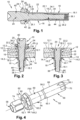
- a blind-type fixing device 10 configured to hold first and second parts 12, 14 together, comprises a tubular body 16, an expanding nut 18 and a screw 20.
- the assembled first and second parts 12, 14 each comprise a through hole 12.1, 14.1, for housing the tubular body 16, and a bearing surface 12.2, 14.2, the bearing surface 12.2 of the first part 12 comprising a chamfer 12.3 around the through hole 12.1.
- the tubular body 16 comprises a main part 22 which extends between first and second ends 22.1, 22.2, a detachable part 24 which comprises a lateral face 24.1 of hexagonal cross-section as well as a breakable junction zone 26 connecting the main part 22 and the detachable part 24.
- the tubular body 16 comprises a through-orifice 28 over its entire length which has a reduction in diameter 28.1 frustoconical at the second end 22.2 of the main part 22.
- the first end 22.1 of the main part 22 comprises a frustoconical shape flared towards the second end 22.2.
- the tubular body 16 comprises, at the second end 22.2 of the main part 22, a frustoconical head 30 configured to be housed in the chamfer 12.3 of the first part 12 in operation.
- the expanding nut 18 extends between first and second ends 18.1, 18.2, the second end 18.2 cooperating with the first end 22.1 of the main portion 22 of the tubular body 16 in operation.
- the expanding nut 18 includes an initially smooth side face 32 and a through hole 34 that connects the first and second ends 18.1, 18.2.
- the expanding nut 18 can deform and expand to form a bulb 36 (visible in the Figures 2 and 3 ) resting against the support surface 14.2 of the second part 14 when the expanding nut 18 is subjected to a compressive force between its first and second ends 18.1, 18.2.
- the through hole 34 has a tapped section 34.2 near the first end 18.1 of the expanding nut 18.
- the screw 20 comprises a rod 38 which extends between first and second ends 38.1, 38.2, a head 40 of hexagonal section for screwing the screw 20 as well as a breakable junction zone 42 connecting the rod 38 and the head 40.
- the rod 38 comprises a threaded section 44, which extends from the first end 38.1, configured to cooperate with the tapped section 34.2 of the expanding nut 18 and to be screwed therein.
- the second end 38.2 of the rod 38 comprises a frustoconical shape configured to cooperate with the diameter reduction 28.1 of the tubular body 16.
- the method of mounting such a fixing device comprises a step of inserting the device into the through holes 12.1, 14.1 of the first and second parts 12, 14 to be assembled from the bearing surface 12.2 until the truncated head 30 of the tubular body 16 is housed in the chamfer 12.3 of the first part 12.
- the first end 22.1 of the main part 22 is located projecting relative to the bearing surface 14.2 of the second part 14.
- the screw 20 is screwed in, the tubular body 16 being immobilized in rotation by means of a tool which cooperates with the detachable part 24 of the tubular body 16.
- the truncated cone shape of the second end 38.2 of the rod 38 of the screw 20 being in abutment against the reduction in diameter 28.1 of the tubular body 16, the expanding nut 18 is compressed between its first and second ends 18.1, 18.2, its second end 18.2 being in contact with the first end 22.1 of the main part 22 of the tubular body 16.
- the screwing then causes the expansion of the expanding nut 18 which then forms a bulb 36. When the latter is formed, the screwing causes the bulb 36 to be pressed against the bearing surface 14.2 of the second part 14.
- the first and second parts 12 and 14 are compressed between the bulb 36 and the truncated head 30 of the tubular body 16.
- the junction zone 42 breaks initially and then, under the effect of a complementary movement of the installation tool, the breakable junction zone 26 breaks in a second stage.
- the fixing device 10 is then correctly tightened. As illustrated in the Figure 3 , the tubular body 16 and the screw 20 are flush with the bearing surface 12.2 of the first part 12.
- This embodiment makes it possible to automate the assembly with a single tool configured to lock the tubular body 16 in rotation and screw the screw.
- one solution consists of destroying the truncated cone shape of the second end 38.2 of the rod 38 using a drill.
- This solution is not satisfactory because the risks of damaging the bearing surface 12.2 of the first part 12 are significant due to the fact that the tubular body 16 and the screw 20 are flush with said bearing surface 12.2 of the first part 12.
- the machining of the screw 20 generates debris which pollutes the environment if it is not collected.
- the expanding nut 18 can remain connected to the tubular body 16 to the extent that the second end 18.2 of the expanding nut can still be nested on the first end 22.1 of the main part 22 of the tubular body 16.
- the present invention aims to remedy all or part of the drawbacks of the prior art.
- the invention relates to a fastening device for holding together at least first and second parts which each comprise a through hole and a bearing surface at which the through hole opens, said fastening device comprising a tubular body, an expanding nut and a screw.
- the tubular body is configured to be housed in the through holes of the first and second parts and extends between first and second ends, the first end of the tubular body cooperating with the expanding nut, the second end of the tubular body having a head configured to bear against the bearing surface of the first part.
- the expanding nut extends between first and second ends and has at least one threaded section and an axis of revolution, the expanding nut being configured to expand so as to form a bulb when it is subjected to a compressive force between its first and second ends.
- the screw comprises a rod which extends between first and second ends and has an axis of revolution as well as an end face at its first end, the rod comprising a threaded section which cooperates with the tapped section of the expanding nut, the second end of the rod comprising an enlarged shape bearing against the tubular body.
- the screw has at least one shape positioned at the level of the transverse face of the rod and configured to cooperate with a first tool in order to immobilize in rotation around its axis of revolution the screw relative to the first tool.
- the expanding nut comprises at least one shape configured to cooperate with a second tool in order to immobilize the expanding nut in rotation around its axis of revolution relative to the second tool.
- This solution does not generate any debris during disassembly, reduces the risk of damage to the first and second parts and allows the tubular body and the expanding nut to be safely separated.
- This fixing device allows disassembly of the assembled parts without risk of damage so that it is not necessary to re-machine the bores of the assembled parts.
- the expanding nut comprises a side face connecting the first and second ends of the expanding nut as well as at least one flat positioned on the side face.
- the side face comprises several flats regularly distributed around the axis of revolution of the expanding nut.
- each flat is positioned near the first end of the expanding nut.
- the rod comprises an imprint, coaxial with the axis of revolution of the screw, which opens at the level of the transverse face and has a bottom as well as a lateral face connecting the bottom and the transverse face, the lateral face comprising at least one flat.
- the imprint includes several flats regularly distributed around the axis of revolution of the screw.
- the head is configured to allow it to be immobilized in rotation or to be driven in rotation with a tool.
- the head of the tubular body extends between first and second transverse faces, the second transverse face being configured to bear against the bearing surface of the first part.
- the head comprises a first section of prismatic section which extends from the first transverse face as well as a second section, which extends between the first section and the second transverse face, of section greater than that of the first section.
- the invention also relates to an assembly comprising at least first and second parts as well as at least one fixing device according to one of the preceding characteristics in order to hold the first and second parts assembled.
- the invention also relates to a method for dismantling a fixing device according to one of the preceding characteristics.
- This dismantling method comprises a step of unscrewing a first element, among the screw and the expanding nut, relative to a second element different from the first element, among the screw and the expanding nut, by immobilizing the second element in rotation using a first tool and by pivoting the first element using a second tool.
- the method comprises a step of unscrewing the expanding nut relative to the screw by immobilizing the screw in rotation using the first tool, which cooperates with the imprint of the screw, and by pivoting the expanding nut using the second tool which cooperates with the flats of the expanding nut.
- the fixing device 52 comprises a tubular body 54 passing through the first and second parts 48, 50, an expanding nut 56 as well as a screw 58 housed in the tubular body and cooperating with the expanding nut 56.
- the tubular body 54 comprises a tubular part 60 which extends between first and second ends 60.1, 60.2, a head 62 which extends between first and second transverse faces 62.1, 62.2 (the second end 60.2 of the tubular part 60 being connected to the second transverse face 62.2) as well as a through orifice T60 which opens at the level of the first end 60.1 of the tubular part 60 and the first transverse face 62.1 of the head 62.
- the tubular part 60 comprises a cylindrical lateral face F60 which has a diameter substantially equal to or slightly smaller than those of the through holes 48.1, 50.1 of the first and second parts 48, 50.
- the through orifice T60 is smooth.
- the first end 60.1 of the tubular part 60 has a truncated cone shape which flares out towards the second end 60.2.
- the through hole T60 comprises a widening, such as a chamfer or a counterbore, at its end opening at the first transverse face 62.1 of the head 62.
- the head 62 comprises a first section 64.1 of prismatic section, in particular hexagonal, which extends from the first transverse face 62.1 as well as a second section 64.2, which extends between the first section 64.1 and the second transverse face 62.2, of circular section and greater than that of the first section 64.1.
- This second section 64.2 forms a false washer.
- the latter allows a better distribution of the forces on the first or second part 48, 50 and a better holding of the fixing device in a setting tool.
- the invention is not limited to this geometry (hexagonal) for the head 62.
- the head 62 is configured to allow it to be immobilized in rotation or to be driven in rotation with a tool.
- the second transverse face 62.2 of the head 62 is configured to be pressed against the bearing surface 48.2 of the first part 48.
- the first section 64.1 is used to immobilize the tubular body 54 in rotation with a tool.
- the tubular body 54 is configured to be housed in the through holes 48.1, 50.1 of the first and second parts 48, 50. It comprises a tubular part 60 which extends between first and second ends 60.1, 60.2 and has an axis of revolution A54, the first end 60.1 cooperating with the expanding nut 56 and having a flared shape in the direction of the second end 60.2, the second end 60.2 having a head 62 configured to bear against the bearing surface 48.2 of the first part 48.
- the expanding nut 56 extends between first and second ends 56.1, 56.2, the second end 56.2 being in contact with the first end 60.1 of the tubular portion 60 of the tubular body 54 in operation.
- the expanding nut 56 includes a side face 66 and a through hole 68 that connects the first and second ends 56.1, 56.2.
- the expanding nut 56 is configured to deform and expand so as to form a bulb B56 (visible in the figure 7 ) when the expanding nut 56 is subjected to a compressive force between its first and second ends 56.1, 56.2. In operation, the bulb B56 bears against the bearing surface 50.2 of the second part 50.
- the lateral face 66 Before deformation, the lateral face 66 has a diameter substantially equal to that of the lateral face F60 of the tubular body 54.
- the expanding nut 56 may be identical to those of the prior art. Whatever the embodiment, the expanding nut 56 extends between first and second ends 56.1, 56.2 and comprises a through hole 68 which opens at the first and second ends 56.1, 56.2. This through hole 68 has at least one threaded section 68.1 and an axis of revolution A56. The second end 56.2 of the expanding nut 56 cooperates with the first end 60.1 of the tubular portion 60 of the tubular body 54 in operation. The expanding nut 56 is configured to deform and expand so as to form a bulb B56 when it is subjected to a compressive force between its first and second ends 56.1, 56.2.
- the expanding nut 56 comprises at least one shape configured to cooperate with a tool in order to immobilize the expanding nut 56 in rotation around its axis of revolution A56 relative to the tool.
- the lateral face 66 of the expanding nut 56 comprises at least one flat 70.
- the lateral face 66 comprises several flats 70 regularly distributed around the axis of revolution A56 of the expanding nut 56.
- the lateral face 66 comprises six flats.
- the invention is not limited to this geometry for the expanding nut 56.
- the expanding nut 56 is configured to cooperate with a tool in order to immobilize it in rotation around its axis of revolution A56 relative to the tool.
- the screw 58 comprises a rod 72 which extends between first and second ends 72.1, 72.2, a head 74 of hexagonal section for screwing the screw 58, as well as a breakable junction zone 76 connecting the rod 72 and the head 74.
- the rod 72 comprises a threaded section 78, which extends from the first end 72.1, configured to cooperate with the tapped section 68.1 of the expanding nut 56 and to be screwed therein.
- the second end 72.2 of the rod 72 comprises an enlarged shape 80 configured to bear against the tubular body 54.
- the screw 58 could be identical to the screws of the prior art.
- the rod 72 of the screw 58 extends between first and second ends 72.1, 72.2 and has an axis of revolution A72 as well that an end face F72, at its first end 72.1, substantially perpendicular to the axis of revolution A72.
- the rod 72 comprises a threaded section 78, which extends from the first end 72.1, configured to cooperate with the tapped section 68.1 of the expanding nut 56 and screw into it, the second end 72.2 of the rod 72 comprising an enlarged shape 80 configured to bear against the tubular body 54.
- the recess 82 comprises six flats and has a hexagonal cross-section. Each flat extends between the end face F72 and the bottom 82.1.
- the invention is not limited to this geometry for the imprint 82.
- the screw 58 is configured to cooperate with a tool in order to immobilize it in rotation around its axis of revolution A58 relative to the tool.
- the fixing device 52 is mounted using substantially the same mounting method as for the fixing devices of the prior art visible in the figures 1 to 3
- a mounting method comprises a step of inserting the device into the through holes 48.1, 50.1 of the first and second parts 48, 50 to be assembled from the bearing surface 48.2 of the first part 48 until the head 62 of the tubular body 54 is in abutment against the bearing surface 48.2 of the first part 48.
- the first end 60.1 of the tubular body 54 is located projecting relative to the bearing surface 50.2 of the second part 50.
- the screw 58 is screwed with a first tool, the tubular body 54 being immobilized in rotation thanks to a second tool which cooperates with the head 62 of the tubular body 54.
- the second section 64.2 of the head 62 which forms a false washer, limits the risks of damage to the first part 48 with the second tool.
- the expanding nut 56 When screwing the screw 58, the expanding nut 56 is compressed between its first and second ends 56.1, 56.2, its second end 56.2 being in contact with the first end 60.1 of the tubular part 60 of the tubular body 54. This screwing thus causes the expansion of the expanding nut 56 which then forms a bulb B56. When the latter is formed, the screwing causes the bulb B56 to be pressed against the bearing surface 50.2 of the second part 50. From then on, the first and second parts 48 and 50 are compressed between the bulb B56 of the expanding nut 56 and the head 62 of the tubular body 54. As soon as a desired tightening torque is reached, the breakable junction zone 76 of the screw 58 breaks. The fixing device 52 is then correctly tightened.
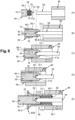
- a method of disassembling the fixing device 52 is described with regard to the figures 8 to 10 .
- This disassembly method comprises a step of unscrewing a first element, among the screw 58 and the expanding nut 56, relative to a second element different from the first element, among the screw 58 and the expanding nut 56, by immobilizing the second element in rotation using a first tool and by pivoting the first element using a second tool.
- the tubular body 54 can be immobilized prior to the unscrewing step to unlock the expanding nut 56.
- the disassembly method comprises a step of unscrewing the expanding nut 56 relative to the screw 58 by immobilizing the screw 58 in rotation using the first tool 84, which cooperates with the imprint 82 of the screw 58, and by pivoting the expanding nut 56 using the second tool 86 which cooperates with the flats 70 of the lateral face 66 of the expanding nut 56.
- the first tool 84 is a hexagonal male key and the second tool 86 is a socket wrench.
- the disassembly method comprises a step of unlocking the expanding nut 56 relative to the tubular body 54 by immobilizing the tubular body 54 in rotation using a third tool 88, which cooperates with the first section 64.1 of the head 62 of the tubular body 54, and by pivoting the expanding nut 56 using the second tool 86.
- the third tool 88 is a socket wrench. This unlocking step becomes necessary if the imprint 82 of the screw 58 is not sufficient to unlock the expanding nut 56 at the start of the unscrewing step due to the significant pressure forces exerted by the expanding nut 56 on the tubular body 54.
- the third tool 88 is fitted onto the head 62 of the tubular body 54.
- the first tool 84 is inserted into the imprint 82 of the screw 58, as illustrated in the Figure 9 and parts (A) and (B) of the figure 8
- the second tool 86 is fitted onto the expanding nut 56 by making it cooperate with the flats 70, as illustrated in parts (C) and (D) of the figure 8 .
- the second tool 86 is then set in rotation, as illustrated in the Figure 9 .
- the expanding nut 56 is unscrewed with the second tool 86 while keeping the screw 58 stationary in rotation thanks to the first tool 84, as illustrated in part (D) of the figure 8 and the Figure 10 .
- the expanding nut 56 is separated from the screw 58. From then on, the tubular body 54 and the screw 58 can be removed from the through holes 48.1, 50.1 of the first and second parts 48, 50.
- This operating mode does not generate any debris and allows the tubular body 54 and the expanding nut 54 to be safely separated.
- the same tool 90 supports the first and second tools 84, 86, the tool 90 comprising a support 92, a fixed connection 94 connecting the support 92 and the first tool 84 as well as a pivoting connection 96 which connects the support 92 and the second tool 86.
Landscapes
- Engineering & Computer Science (AREA)
- General Engineering & Computer Science (AREA)
- Mechanical Engineering (AREA)
- Dowels (AREA)
Abstract
Description
- La présente demande se rapporte à un dispositif de fixation démontable de type aveugle, à un assemblage comportant au moins un tel dispositif de fixation ainsi qu'à un procédé de démontage d'un tel dispositif de fixation.
- Selon un mode de réalisation visible sur les
figures 1 à 3 et décrit dans le documentEP2647851 , un dispositif de fixation 10 de type aveugle, configuré pour maintenir assemblées des première et deuxième pièces 12, 14, comprend un corps tubulaire 16, un écrou expansible 18 ainsi qu'une vis 20. Les première et deuxième pièces assemblées 12, 14 comprennent chacune un trou traversant 12.1, 14.1, pour loger le corps tubulaire 16, et une surface d'appui 12.2, 14.2, la surface d'appui 12.2 de la première pièce 12 comprenant un chanfrein 12.3 autour du trou traversant 12.1. - Le corps tubulaire 16 comprend une partie principale 22 qui s'étend entre des première et deuxième extrémités 22.1, 22.2, une partie détachable 24 qui comprend une face latérale 24.1 de section transversale hexagonale ainsi qu'une zone de jonction sécable 26 reliant la partie principale 22 et la partie détachable 24. Le corps tubulaire 16 comprend un orifice traversant 28 sur toute sa longueur qui présente une réduction de diamètre 28.1 tronconique au droit de la deuxième extrémité 22.2 de la partie principale 22. La première extrémité 22.1 de la partie principale 22 comprend une forme tronconique évasée en direction de la deuxième extrémité 22.2. Le corps tubulaire 16 comprend, au niveau de la deuxième extrémité 22.2 de la partie principale 22, une tête tronconique 30 configurée pour se loger dans le chanfrein 12.3 de la première pièce 12 en fonctionnement.
- L'écrou expansible 18 s'étend entre des première et deuxième extrémités 18.1, 18.2, la deuxième extrémité 18.2 coopérant avec la première extrémité 22.1 de la partie principale 22 du corps tubulaire 16 en fonctionnement. L'écrou expansible 18 comprend une face latérale 32 initialement lisse ainsi qu'un trou traversant 34 qui relie les première et deuxième extrémités 18.1, 18.2. L'écrou expansible 18 peut se déformer et s'expanser de manière à former un bulbe 36 (visible sur les
figures 2 et 3 ) prenant appui contre la surface d'appui 14.2 de la deuxième pièce 14 lorsque l'écrou expansible 18 est soumis à un effort de compression entre ses première et deuxième extrémités 18.1, 18.2. - Le trou traversant 34 présente un tronçon taraudé 34.2 à proximité de la première extrémité 18.1 de l'écrou expansible 18.
- La vis 20 comprend une tige 38 qui s'étend entre des première et deuxième extrémités 38.1, 38.2, une tête 40 de section hexagonale pour visser la vis 20 ainsi qu'une zone de jonction sécable 42 reliant la tige 38 et la tête 40. La tige 38 comprend un tronçon fileté 44, qui s'étend à partir de la première extrémité 38.1, configuré pour coopérer avec le tronçon taraudé 34.2 de l'écrou expansible 18 et s'y visser. La deuxième extrémité 38.2 de la tige 38 comprend une forme tronconique configurée pour coopérer avec la réduction de diamètre 28.1 du corps tubulaire 16.
- Le procédé de montage d'un tel dispositif de fixation comprend une étape d'insertion du dispositif dans les trous traversants 12.1, 14.1 des première et deuxième pièces 12, 14 à assembler depuis la surface d'appui 12.2 jusqu'à ce que la tête tronconique 30 du corps tubulaire 16 soit logée dans le chanfrein 12.3 de la première pièce 12. La première extrémité 22.1 de la partie principale 22 est située en saillie par rapport à la surface d'appui 14.2 de la deuxième pièce 14.
- En suivant, la vis 20 est vissée, le corps tubulaire 16 étant immobilisé en rotation grâce à un outil qui coopère avec la partie détachable 24 du corps tubulaire 16. La forme tronconique de la deuxième extrémité 38.2 de la tige 38 de la vis 20 étant en butée contre la réduction de diamètre 28.1 du corps tubulaire 16, l'écrou expansible 18 est comprimé entre ses première et deuxième extrémités 18.1, 18.2, sa deuxième extrémité 18.2 étant en contact avec la première extrémité 22.1 de la partie principale 22 du corps tubulaire 16. Le vissage provoque alors l'expansion de l'écrou expansible 18 qui forme alors un bulbe 36. Lorsque ce dernier est formé, le vissage provoque un plaquage du bulbe 36 contre la surface d'appui 14.2 de la deuxième pièce 14. Dès lors, les première et deuxième pièces 12 et 14 sont comprimées entre le bulbe 36 et la tête tronconique 30 du corps tubulaire 16. Dès que le couple de serrage souhaité est atteint, la zone de jonction 42 se rompt dans un premier temps puis, sous l'effet d'un mouvement complémentaire de l'outil de pose, la zone de jonction sécable 26 se rompt dans un second temps. Le dispositif de fixation 10 est alors correctement serré. Comme illustré sur la
figure 3 , le corps tubulaire 16 et la vis 20 affleurent la surface d'appui 12.2 de la première pièce 12. - Ce mode de réalisation permet d'automatiser le montage avec un seul outil configuré pour bloquer en rotation le corps tubulaire 16 et visser la vis.
- Pour démonter d'un tel dispositif de fixation, une solution consiste à détruire à l'aide d'un foret la forme tronconique de la deuxième extrémité 38.2 de la tige 38. Cette solution n'est pas satisfaisante car les risques d'endommagement de la surface d'appui 12.2 de la première pièce 12 sont importants du fait que le corps tubulaire 16 et la vis 20 affleurent ladite surface d'appui 12.2 de la première pièce 12. Selon un autre inconvénient, l'usinage de la vis 20 génère des débris qui polluent l'environnement s'ils ne sont pas collectés. Enfin, même si la forme tronconique de la deuxième extrémité 38.2 de la tige 38 est détruite, l'écrou expansible 18 peut rester lié au corps tubulaire 16 dans la mesure où la deuxième extrémité 18.2 de l'écrou expansible peut toujours être imbriquée sur la première extrémité 22.1 de la partie principale 22 du corps tubulaire 16.
- La présente invention vise à remédier à tout ou partie des inconvénients de l'art antérieur.
- A cet effet, l'invention a pour objet un dispositif de fixation permettant de maintenir assemblées au moins des première et deuxième pièces qui comportent chacune un trou traversant ainsi qu'une surface d'appui au niveau de laquelle débouche le trou traversant, ledit dispositif de fixation comportant un corps tubulaire, un écrou expansible ainsi qu'une vis. Le corps tubulaire est configuré pour se loger dans les trous traversants des première et deuxième pièces et s'étend entre des première et deuxième extrémités, la première extrémité du corps tubulaire coopérant avec l'écrou expansible, la deuxième extrémité du corps tubulaire présentant une tête configurée pour prendre appui contre la surface d'appui de la première pièce. L'écrou expansible s'étend entre des première et deuxième extrémités et présente au moins un tronçon taraudé et un axe de révolution, l'écrou expansible étant configuré pour s'expanser de manière à former un bulbe lorsqu'il est soumis à un effort de compression entre ses première et deuxième extrémités. La vis comporte une tige qui s'étend entre des première et deuxième extrémités et présente un axe de révolution ainsi qu'une face terminale au niveau de sa première extrémité, la tige comprenant un tronçon fileté qui coopère avec le tronçon taraudé de l'écrou expansible, la deuxième extrémité de la tige comprenant une forme élargie prenant appui contre le corps tubulaire.
- Selon l'invention, la vis présente au moins une forme positionnée au niveau de la face transversale de la tige et configurée pour coopérer avec un premier outil afin d'immobiliser en rotation autour de son axe de révolution la vis par rapport au premier outil. En complément, l'écrou expansible comprend au moins une forme configurée pour coopérer avec un deuxième outil afin d'immobiliser en rotation autour de son axe de révolution l'écrou expansible par rapport au deuxième outil.
- Cette solution ne génère aucun débris lors du démontage, réduit les risques d'endommagement des première et deuxième pièces et permet de désolidariser de manière sûre le corps tubulaire et l'écrou expansible. Ce dispositif de fixation permet un démontage des pièces assemblées sans risques d'endommagement si bien qu'il n'est pas nécessaire de ré-usiner les alésages des pièces assemblées.
- Selon une autre caractéristique, l'écrou expansible comprend une face latérale reliant les première et deuxième extrémités de l'écrou expansible ainsi qu'au moins un méplat positionné sur la face latérale.
- Selon une autre caractéristique, la face latérale comprend plusieurs méplats régulièrement répartis autour de l'axe de révolution de l'écrou expansible.
- Selon une autre caractéristique, chaque méplat est positionné à proximité de la première extrémité de l'écrou expansible.
- Selon une autre caractéristique, la tige comprend une empreinte, coaxiale à l'axe de révolution de la vis, qui débouche au niveau de la face transversale et présente un fond ainsi qu'une face latérale reliant le fond et la face transversale, la face latérale comportant au moins un méplat.
- Selon une autre caractéristique, l'empreinte comprend plusieurs méplats régulièrement répartis autour de l'axe de révolution de la vis.
- Selon une autre caractéristique, la tête est configurée pour permettre de l'immobiliser en rotation ou de l'entraîner en rotation avec un outil.
- Selon une autre caractéristique, la tête du corps tubulaire s'étend entre des première et deuxième faces transversales, la deuxième face transversale étant configurée pour prendre appui contre la surface d'appui de la première pièce. En complément, la tête comprend un premier tronçon de section prismatique qui s'étend à partir de la première face transversale ainsi qu'un deuxième tronçon, qui s'étend entre le premier tronçon et la deuxième face transversale, de section supérieure à celle du premier tronçon.
- L'invention a également pour objet un assemblage comportant au moins des première et deuxième pièces ainsi qu'au moins un dispositif de fixation selon l'une des caractéristiques précédentes afin de maintenir les première et deuxième pièces assemblées.
- L'invention a également pour objet un procédé de démontage d'un dispositif de fixation selon l'une des caractéristiques précédentes. Ce procédé de démontage comprend une étape de dévissage d'un premier élément, parmi la vis et l'écrou expansible, par rapport à un deuxième élément différent du premier élément, parmi la vis et l'écrou expansible, en immobilisant en rotation le deuxième élément grâce à un premier outil et en faisant pivoter le premier élément grâce à un deuxième outil.
- Selon une autre caractéristique, le procédé comprend une étape de dévissage de l'écrou expansible par rapport à la vis en immobilisant en rotation la vis grâce au premier outil, qui coopère avec l'empreinte de la vis, et en faisant pivoter l'écrou expansible grâce au deuxième outil qui coopère avec les méplats de l'écrou expansible.
- Selon une autre caractéristique, préalablement à l'étape de dévissage de l'écrou expansible par rapport à la vis ou au début de cette étape de dévissage, le procédé de démontage comprend une étape de déblocage de l'écrou expansible par rapport au corps tubulaire en immobilisant en rotation le corps tubulaire grâce à un troisième outil, qui coopère avec la tête du corps tubulaire, et en faisant pivoter l'écrou expansible grâce au deuxième outil. D'autres caractéristiques et avantages ressortiront de la description de l'invention qui va suivre, description donnée à titre d'exemple uniquement, en regard des dessins annexés parmi lesquels :
- La
figure 1 est une coupe longitudinale d'un dispositif de fixation illustrant un mode de réalisation de l'art antérieur, - La
figure 2 est une coupe d'un assemblage comportant un dispositif de fixation en cours de montage illustrant un mode de réalisation de l'art antérieur, - La
figure 3 est une coupe d'un assemblage comportant un dispositif de fixation en fin de montage illustrant un mode de réalisation de l'art antérieur, - La
figure 4 est une vue en perspective selon un premier angle de vue d'un dispositif de fixation illustrant un mode de réalisation de l'invention, - La
figure 5 est une vue en perspective selon un deuxième angle de vue du dispositif de fixation visible sur lafigure 4 , - La
figure 6 est une vue en perspective du dispositif de fixation visible sur lafigure 4 à l'état désassemblé, - La
figure 7 est une coupe d'un assemblage comportant un dispositif de fixation illustrant un mode de réalisation de l'invention, - La
figure 8 représente des coupes illustrant différentes étapes d'un procédé de démontage du dispositif de fixation visible sur lafigure 4 , - La
figure 9 est une coupe longitudinale d'un dispositif de fixation et d'un outillage de démontage illustrant une étape d'un procédé de démontage, et - La
figure 10 est une coupe longitudinale du dispositif de fixation et de l'outillage de démontage visibles sur lafigure 9 illustrant une autre étape du procédé de démontage. - Le dispositif de fixation 52 comprend un corps tubulaire 54 traversant les première et deuxième pièces 48, 50, un écrou expansible 56 ainsi qu'une vis 58 se logeant dans le corps tubulaire et coopérant avec l'écrou expansible 56.
- Selon un mode de réalisation visible sur les
figures 4 à 6 , le corps tubulaire 54 comprend une partie tubulaire 60 qui s'étend entre des première et deuxième extrémités 60.1, 60.2, une tête 62 qui s'étend entre des première et deuxième faces transversales 62.1, 62.2 (la deuxième extrémité 60.2 de la partie tubulaire 60 étant reliée à la deuxième face transversale 62.2) ainsi qu'un orifice traversant T60 qui débouche au niveau de la première extrémité 60.1 de la partie tubulaire 60 et de la première face transversale 62.1 de la tête 62. - Selon une configuration, la partie tubulaire 60 comporte une face latérale F60 cylindrique qui présente un diamètre sensiblement égal ou légèrement inférieur à ceux des trous traversants 48.1, 50.1 des première et deuxième pièces 48, 50. L'orifice traversant T60 est lisse.
- La première extrémité 60.1 de la partie tubulaire 60 présente une forme tronconique qui s'évase en direction de la deuxième extrémité 60.2.
- L'orifice traversant T60 comprend un élargissement, comme un chanfrein ou un lamage, au niveau de son extrémité débouchant au niveau de la première face transversale 62.1 de la tête 62.
- Selon un mode de réalisation, la tête 62 comprend un premier tronçon 64.1 de section prismatique, notamment hexagonale, qui s'étend à partir de la première face transversale 62.1 ainsi qu'un deuxième tronçon 64.2, qui s'étend entre le premier tronçon 64.1 et la deuxième face transversale 62.2, de section circulaire et supérieure à celle du premier tronçon 64.1. Ce deuxième tronçon 64.2 forme une fausse rondelle. Cette dernière permet une meilleure répartition des efforts sur la première ou deuxième pièce 48, 50 et un meilleur maintien du dispositif de fixation dans un outil de pose. Bien entendu, l'invention n'est pas limitée à cette géométrie (hexagonale) pour la tête 62. Quel que soit le mode de réalisation, la tête 62 est configurée pour permettre de l'immobiliser en rotation ou de l'entraîner en rotation avec un outil.
- En fonctionnement, la deuxième face transversale 62.2 de la tête 62 est configurée pour être plaquée contre la surface d'appui 48.2 de la première pièce 48. Le premier tronçon 64.1 est utilisé pour immobiliser en rotation le corps tubulaire 54 avec un outil.
- Bien entendu, l'invention n'est pas limitée à ce mode de réalisation pour le corps tubulaire 54. Ce dernier pourrait être identique à ceux de l'art antérieur. Quel que soit le mode de réalisation, le corps tubulaire 54 est configuré pour se loger dans les trous traversants 48.1, 50.1 des première et deuxième pièces 48, 50. Il comprend une partie tubulaire 60 qui s'étend entre des première et deuxième extrémités 60.1, 60.2 et présente un axe de révolution A54, la première extrémité 60.1 coopérant avec l'écrou expansible 56 et comportant une forme évasée en direction de la deuxième extrémité 60.2, la deuxième extrémité 60.2 présentant une tête 62 configurée pour prendre appui contre la surface d'appui 48.2 de la première pièce 48.
- L'écrou expansible 56 s'étend entre des première et deuxième extrémités 56.1, 56.2, la deuxième extrémité 56.2 étant en contact avec la première extrémité 60.1 de la partie tubulaire 60 du corps tubulaire 54 en fonctionnement. L'écrou expansible 56 comprend une face latérale 66 ainsi qu'un trou traversant 68 qui relie les première et deuxième extrémités 56.1, 56.2. L'écrou expansible 56 est configuré pour se déformer et s'expanser de manière à former un bulbe B56 (visible sur la
figure7 ) lorsque l'écrou expansible 56 est soumis à un effort de compression entre ses première et deuxième extrémités 56.1, 56.2. En fonctionnement, le bulbe B56 prend appui contre la surface d'appui 50.2 de la deuxième pièce 50. - Avant déformation, la face latérale 66 présente un diamètre sensiblement égal à celui de la face latérale F60 du corps tubulaire 54.
- Le trou traversant 68 présente un tronçon taraudé 68.1 qui s'étend à partir de la première extrémité 56.1 de l'écrou expansible 56.
- A l'exception de sa face latérale 66, l'écrou expansible 56 peut être identique à ceux de l'art antérieur. Quel que soit le mode de réalisation, l'écrou expansible 56 s'étend entre des première et deuxième extrémités 56.1, 56.2 et comprend un trou traversant 68 qui débouche au niveau des première et deuxième extrémités 56.1, 56.2. Ce trou traversant 68 présente au moins un tronçon taraudé 68.1 et un axe de révolution A56. La deuxième extrémité 56.2 de l'écrou expansible 56 coopère avec la première extrémité 60.1 de la partie tubulaire 60 du corps tubulaire 54 en fonctionnement. L'écrou expansible 56 est configuré pour se déformer et s'expanser de manière à former un bulbe B56 lorsqu'il est soumis à un effort de compression entre ses première et deuxième extrémités 56.1, 56.2.
- Selon une particularité de l'invention, l'écrou expansible 56 comprend au moins une forme configurée pour coopérer avec un outil afin d'immobiliser en rotation autour de son axe de révolution A56 l'écrou expansible 56 par rapport à l'outil. Selon un mode de réalisation, la face latérale 66 de l'écrou expansible 56 comprend au moins un méplat 70. Selon une configuration, la face latérale 66 comprend plusieurs méplats 70 régulièrement répartis autour de l'axe de révolution A56 de l'écrou expansible 56. A titre d'exemple, la face latérale 66 comprend six méplats. Bien entendu, l'invention n'est pas limitée à cette géométrie pour l'écrou expansible 56. Quel que soit le mode de réalisation, l'écrou expansible 56 est configuré pour coopérer avec un outil afin de l'immobiliser en rotation autour de son axe de révolution A56 par rapport à l'outil.
- Selon un agencement, chaque méplat 70 est positionné à proximité de la première extrémité 56.1 de l'écrou expansible 56. Les méplats ont tous la même longueur (dimension prise selon une direction parallèle à l'axe de révolution A56 de l'écrou expansible 56) et sont positionnés entre deux plans transversaux.
- La vis 58 comprend une tige 72 qui s'étend entre des première et deuxième extrémités 72.1, 72.2, une tête 74 de section hexagonale pour visser la vis 58, ainsi qu'une zone de jonction sécable 76 reliant la tige 72 et la tête 74. La tige 72 comprend un tronçon fileté 78, qui s'étend à partir de la première extrémité 72.1, configuré pour coopérer avec le tronçon taraudé 68.1 de l'écrou expansible 56 et s'y visser. La deuxième extrémité 72.2 de la tige 72 comprend une forme élargie 80 configurée pour prendre appui contre le corps tubulaire 54.
- A l'exception de la première extrémité 72.1 de sa tige 72, la vis 58 pourrait être identique aux vis de l'art antérieur. Quel que soit le mode de réalisation, la tige 72 de la vis 58 s'étend entre des première et deuxième extrémités 72.1, 72.2 et présente un axe de révolution A72 ainsi qu'une face terminale F72, au niveau de sa première extrémité 72.1, sensiblement perpendiculaire à l'axe de révolution A72. La tige 72 comprend un tronçon fileté 78, qui s'étend à partir de la première extrémité 72.1, configuré pour coopérer avec le tronçon taraudé 68.1 de l'écrou expansible 56 et s'y visser, la deuxième extrémité 72.2 de la tige 72 comprenant une forme élargie 80 configurée pour prendre appui contre le corps tubulaire 54. Selon une particularité de l'invention, la vis 58 présente au moins une forme positionnée au niveau de la face terminale F72 et configurée pour coopérer avec un outil afin d'immobiliser en rotation autour de son axe de révolution A58 la vis 58 par rapport à l'outil. Selon un mode de réalisation, la tige 72 comprend une empreinte 82, coaxiale à l'axe de révolution A58 de la vis 58, qui débouche au niveau de la face terminale F72 et présente un fond 82.1 ainsi qu'une face latérale 82.2 reliant le fond 82.1 et la face terminale F72, la face latérale 82.2 comportant au moins un méplat. Selon un agencement, l'empreinte 82 comprend plusieurs méplats régulièrement répartis autour de l'axe de révolution A58 de la vis 58. Selon un agencement, l'empreinte 82 comprend six méplats et présente une section transversale hexagonale. Chaque méplat s'étend entre la face terminale F72 et le fond 82.1. Bien entendu, l'invention n'est pas limitée à cette géométrie pour l'empreinte 82. Quel que soit le mode de réalisation, la vis 58 est configurée pour coopérer avec un outil afin de l'immobiliser en rotation autour de son axe de révolution A58 par rapport à l'outil.
- Selon un mode opératoire, le dispositif de fixation 52 est monté en utilisant sensiblement le même procédé de montage que pour les dispositifs de fixation de l'art antérieur visibles sur les
figures 1 à 3 - Ainsi, un procédé de montage comprend une étape d'insertion du dispositif dans les trous traversants 48.1, 50.1 des première et deuxième pièces 48, 50 à assembler depuis la surface d'appui 48.2 de la première pièce 48 jusqu'à ce que la tête 62 du corps tubulaire 54 soit en appui contre la surface d'appui 48.2 de la première pièce 48. La première extrémité 60.1 du corps tubulaire 54 est située en saillie par rapport à la surface d'appui 50.2 de la deuxième pièce 50.
- En suivant, la vis 58 est vissée avec un premier outil, le corps tubulaire 54 étant immobilisé en rotation grâce à un deuxième outil qui coopère avec la tête 62 du corps tubulaire 54. Le deuxième tronçon 64.2 de la tête 62, qui forme une fausse rondelle, limite les risques d'endommagement de la première pièce 48 avec le deuxième outil.
- Lors du vissage de la vis 58, l'écrou expansible 56 est comprimé entre ses première et deuxième extrémités 56.1, 56.2, sa deuxième extrémité 56.2 étant en contact avec la première extrémité 60.1 de la partie tubulaire 60 du corps tubulaire 54. Ce vissage provoque ainsi l'expansion de l'écrou expansible 56 qui forme alors un bulbe B56. Lorsque ce dernier est formé, le vissage provoque le plaquage du bulbe B56 contre la surface d'appui 50.2 de la deuxième pièce 50. Dès lors, les première et deuxième pièces 48 et 50 sont comprimées entre le bulbe B56 de l'écrou expansible 56 et la tête 62 du corps tubulaire 54. Dès qu'un couple de serrage souhaité est atteint, la zone de jonction sécable 76 de la vis 58 se rompt. Le dispositif de fixation 52 est alors correctement serré.
- Un procédé de démontage du dispositif de fixation 52 est décrit au regard des
figures 8 à 10 . Ce procédé de démontage comprend une étape de dévissage d'un premier élément, parmi la vis 58 et l'écrou expansible 56, par rapport à un deuxième élément différent du premier élément, parmi la vis 58 et l'écrou expansible 56, en immobilisant en rotation le deuxième élément grâce à un premier outil et en faisant pivoter le premier élément grâce à un deuxième outil. Selon un mode opératoire, le corps tubulaire 54 peut être immobilisé préalablement à l'étape de dévissage pour débloquer l'écrou expansible 56. - Selon un mode de réalisation privilégié visible sur les
figures 8 à 10 , le procédé de démontage comprend une étape de dévissage de l'écrou expansible 56 par rapport à la vis 58 en immobilisant en rotation la vis 58 grâce au premier outil 84, qui coopère avec l'empreinte 82 de la vis 58, et en faisant pivoter l'écrou expansible 56 grâce au deuxième outil 86 qui coopère avec les méplats 70 de la face latérale 66 de l'écrou expansible 56. A titre d'exemple, le premier outil 84 est une clé mâle à six pans et le deuxième outil 86 est une clé à douille. Selon un mode de réalisation, préalablement à l'étape de dévissage de l'écrou expansible 56 par rapport à la vis 58 ou au début de cette étape de dévissage, le procédé de démontage comprend une étape de déblocage de l'écrou expansible 56 par rapport au corps tubulaire 54 en immobilisant en rotation le corps tubulaire 54 grâce à un troisième outil 88, qui coopère avec le premier tronçon 64.1 de la tête 62 du corps tubulaire 54, et en faisant pivoter l'écrou expansible 56 grâce au deuxième outil 86. A titre d'exemple, le troisième outil 88 est une clé à douille. Cette étape de déblocage devient nécessaire si l'empreinte 82 de la vis 58 n'est pas suffisante pour débloquer l'écrou expansible 56 au début de l'étape de dévissage en raison des efforts de pression importants exercés par l'écrou expansible 56 sur le corps tubulaire 54. Comme illustré sur lafigure 9 , dans un premier temps, le troisième outil 88 est emmanché sur la tête 62 du corps tubulaire 54. En suivant, le premier outil 84 est inséré dans l'empreinte 82 de la vis 58, comme illustré sur lafigure 9 et les parties (A) et (B) de lafigure 8 , et le deuxième outil 86 est emmanché sur l'écrou expansible 56 en le faisant coopérer avec les méplats 70, comme illustré sur les parties (C) et (D) de lafigure 8 . Le troisième outil 88 immobilisant en rotation le corps tubulaire 54, le deuxième outil 86 est alors mis en rotation, comme illustré sur lafigure 9 . Puis, l'écrou expansible 56 est dévissé avec le deuxième outil 86 en maintenant immobile en rotation la vis 58 grâce au premier outil 84, comme illustré sur la partie (D) de lafigure 8 et lafigure 10 . - A l'issue de l'étape de dévissage, l'écrou expansible 56 est désolidarisé de la vis 58. Dès lors, le corps tubulaire 54 et la vis 58 peuvent être retirés des trous traversants 48.1, 50.1 des première et deuxième pièces 48, 50.
- Ce mode opératoire ne génère aucun débris et permet de désolidariser de manière sûre le corps tubulaire 54 et l'écrou expansible 54.
- Selon un mode de réalisation visible sur les
figures 9 et 10 , un même outillage 90 supporte les premier et deuxième outils 84, 86, l'outillage 90 comprenant un support 92, une liaison fixe 94 reliant le support 92 et le premier outil 84 ainsi qu'une liaison pivotante 96 qui relie le support 92 et le deuxième outil 86.
Claims (12)
- Dispositif de fixation permettant de maintenir assemblées au moins des première et deuxième pièces (48, 50) qui comportent chacune un trou traversant (48.1, 50.1) ainsi qu'une surface d'appui (48.2, 50.2) au niveau de laquelle débouche le trou traversant (48.1, 50.1), ledit dispositif de fixation comportant un corps tubulaire (54), un écrou expansible (56) ainsi qu'une vis (58) ; le corps tubulaire (54) étant configuré pour se loger dans les trous traversants (48.1, 50.1) des première et deuxième pièces (48, 50) et s'étendant entre des première et deuxième extrémités (60.1, 60.2), la première extrémité (60.1) du corps tubulaire (54) coopérant avec l'écrou expansible (56), la deuxième extrémité (60.2) du corps tubulaire (54) présentant une tête (62) configurée pour prendre appui contre la surface d'appui (48.2) de la première pièce (48) ; l'écrou expansible (56) s'étendant entre des première et deuxième extrémités (56.1, 56.2), présentant au moins un tronçon taraudé (68.1) et un axe de révolution (A56), l'écrou expansible (56) étant configuré pour s'expanser de manière à former un bulbe (B56) lorsqu'il est soumis à un effort de compression entre ses première et deuxième extrémités (56.1, 56.2) ; la vis (58) comportant une tige (72) qui s'étend entre des première et deuxième extrémités (72.1, 72.2) et présente un axe de révolution (A72) ainsi qu'une face terminale (F72) au niveau de sa première extrémité (72.1), la tige (72) comprenant un tronçon fileté (78) qui coopère avec le tronçon taraudé (68.1) de l'écrou expansible (56), la deuxième extrémité (72.2) de la tige (72) comprenant une forme élargie (80) prenant appui contre le corps tubulaire (54) ; caractérisé en ce que la vis (58) présente au moins une forme, au niveau de la face transversale (F72) de la tige (72), configurée pour coopérer avec un premier outil (84) afin d'immobiliser en rotation autour de son axe de révolution (A72) la vis (58) par rapport au premier outil (84) et en ce que l'écrou expansible (56) comprend au moins une forme configurée pour coopérer avec un deuxième outil (86) afin d'immobiliser en rotation autour de son axe de révolution (A56) l'écrou expansible (56) par rapport au deuxième outil (86).
- Dispositif de fixation selon la revendication précédente, caractérisé en ce que l'écrou expansible (56) comprend une face latérale (66) reliant les première et deuxième extrémités (56.1, 56.2) de l'écrou expansible (56) ainsi qu'au moins un méplat (70) positionné sur la face latérale (66).
- Dispositif de fixation selon la revendication précédente, caractérisé en ce que la face latérale (66) comprend plusieurs méplats (70) régulièrement répartis autour de l'axe de révolution (A56) de l'écrou expansible (56).
- Dispositif de fixation selon l'une des revendications 2 à 3, caractérisé en ce que chaque méplat (70) est positionné à proximité de la première extrémité (56.1) de l'écrou expansible (56).
- Dispositif de fixation selon l'une des revendications précédentes, caractérisé en ce que la tige (72) comprend une empreinte (82), coaxiale à l'axe de révolution (A58) de la vis (58), qui débouche au niveau de la face transversale (F72) et présente un fond (82.1) ainsi qu'une face latérale (82.2) reliant le fond (82.1) et la face transversale (F72), la face latérale (82.2) comportant au moins un méplat.
- Dispositif de fixation selon la revendication précédente, caractérisé en ce que l'empreinte (82) comprend plusieurs méplats régulièrement répartis autour de l'axe de révolution (A58) de la vis (58).
- Dispositif de fixation selon l'une des revendications précédentes, caractérisé en ce que la tête (62) est configurée pour permettre de l'immobiliser en rotation ou de l'entraîner en rotation avec un outil.
- Dispositif de fixation selon la revendication précédente, caractérisé en ce que la tête (62) du corps tubulaire (54) s'étend entre des première et deuxième faces transversales (62.1, 62.2), la deuxième face transversale (62.2) étant configurée pour prendre appui contre la surface d'appui (48.2) de la première pièce (48) et en ce que la tête (62) comprend un premier tronçon (64.1) de section prismatique qui s'étend à partir de la première face transversale (62.1) ainsi qu'un deuxième tronçon (64.2) qui s'étend entre le premier tronçon (64.1) et la deuxième face transversale (62.2), de section supérieure à celle du premier tronçon (64.1).
- Assemblage comportant au moins des première et deuxième pièces (48, 50) ainsi qu'au moins un dispositif de fixation selon l'une des revendications précédentes pour maintenir les première et deuxième pièces (48, 50) assemblées.
- Procédé de démontage d'un dispositif de fixation selon l'une des revendications 1 à 8, caractérisé en ce que le procédé de démontage comprend une étape de dévissage d'un premier élément, parmi la vis (58) et l'écrou expansible (56), par rapport à un deuxième élément différent du premier élément, parmi la vis (58) et l'écrou expansible (56), en immobilisant en rotation le deuxième élément grâce à un premier outil (84) et en faisant pivoter le premier élément grâce à un deuxième outil (86).
- Procédé de démontage selon la revendication précédente, caractérisé en ce que le procédé comprend une étape de dévissage de l'écrou expansible (56) par rapport à la vis (58) en immobilisant en rotation la vis (58) grâce au premier outil (84), qui coopère avec l'empreinte (82) de la vis (58), et en faisant pivoter l'écrou expansible (56) grâce au deuxième outil (86) qui coopère avec les méplats (70) de l'écrou expansible (56).
- Procédé de démontage selon la revendication précédente, caractérisé en ce que, préalablement à l'étape de dévissage de l'écrou expansible (56) par rapport à la vis (58) ou au début de cette étape de dévissage, le procédé de démontage comprend une étape de déblocage de l'écrou expansible (56) par rapport au corps tubulaire (54) en immobilisant en rotation le corps tubulaire (54) grâce à un troisième outil (88) qui coopère avec la tête (62) du corps tubulaire (54) et en faisant pivoter l'écrou expansible (56) grâce au deuxième outil (86).
Applications Claiming Priority (1)
| Application Number | Priority Date | Filing Date | Title |
|---|---|---|---|
| FR2311261A FR3154465A1 (fr) | 2023-10-18 | 2023-10-18 | Dispositif de fixation démontable de type aveugle, assemblage comportant au moins un tel dispositif de fixation et procédé de démontage d’un tel dispositif de fixation |
Publications (2)
| Publication Number | Publication Date |
|---|---|
| EP4542063A1 true EP4542063A1 (fr) | 2025-04-23 |
| EP4542063B1 EP4542063B1 (fr) | 2026-03-18 |
Family
ID=89308473
Family Applications (1)
| Application Number | Title | Priority Date | Filing Date |
|---|---|---|---|
| EP24205128.2A Active EP4542063B1 (fr) | 2023-10-18 | 2024-10-08 | Dispositif de fixation démontable de type aveugle, assemblage comportant au moins un tel dispositif de fixation et procédé de démontage d'un tel dispositif de fixation |
Country Status (4)
| Country | Link |
|---|---|
| US (1) | US12540638B2 (fr) |
| EP (1) | EP4542063B1 (fr) |
| CN (1) | CN119844474A (fr) |
| FR (1) | FR3154465A1 (fr) |
Families Citing this family (3)
| Publication number | Priority date | Publication date | Assignee | Title |
|---|---|---|---|---|
| DE102022109926A1 (de) * | 2022-04-25 | 2023-10-26 | Norma Germany Gmbh | Schelle mit Spannschraube und Drehmomentbegrenzung |
| USD1123595S1 (en) * | 2023-07-11 | 2026-04-28 | Hi-Shear Corporation | Fastener |
| USD1119494S1 (en) * | 2024-03-15 | 2026-03-24 | Yuexiang Wang | Riveting tool |
Citations (3)
| Publication number | Priority date | Publication date | Assignee | Title |
|---|---|---|---|---|
| WO2012142033A2 (fr) * | 2011-04-14 | 2012-10-18 | Pratt John D | Dispositif de fixation et son procédé d'installation |
| EP2647851A1 (fr) | 2012-04-04 | 2013-10-09 | John D. Pratt | Élément de fixation et son procédé d'installation |
| WO2018224793A1 (fr) * | 2017-06-09 | 2018-12-13 | Eris | Outil de pose d'une fixation aveugle, procédé de pose et fixation aveugle adaptée |
Family Cites Families (3)
| Publication number | Priority date | Publication date | Assignee | Title |
|---|---|---|---|---|
| US3443474A (en) * | 1967-12-27 | 1969-05-13 | Vsi Corp | Blind fastener |
| US5213460A (en) * | 1991-05-24 | 1993-05-25 | Huck International, Inc. | High strength blind bolt with uniform high clamp over an extended grip range |
| US8517649B2 (en) * | 2006-10-05 | 2013-08-27 | Monogram Aerospace Fasteners, Inc. | Dual-action disposable clamp |
-
2023
- 2023-10-18 FR FR2311261A patent/FR3154465A1/fr not_active Ceased
-
2024
- 2024-10-08 EP EP24205128.2A patent/EP4542063B1/fr active Active
- 2024-10-16 US US18/916,784 patent/US12540638B2/en active Active
- 2024-10-17 CN CN202411449543.1A patent/CN119844474A/zh active Pending
Patent Citations (4)
| Publication number | Priority date | Publication date | Assignee | Title |
|---|---|---|---|---|
| WO2012142033A2 (fr) * | 2011-04-14 | 2012-10-18 | Pratt John D | Dispositif de fixation et son procédé d'installation |
| EP2647851A1 (fr) | 2012-04-04 | 2013-10-09 | John D. Pratt | Élément de fixation et son procédé d'installation |
| EP2647851B1 (fr) * | 2012-04-04 | 2017-06-14 | John D. Pratt | Élément de fixation et son procédé d'installation |
| WO2018224793A1 (fr) * | 2017-06-09 | 2018-12-13 | Eris | Outil de pose d'une fixation aveugle, procédé de pose et fixation aveugle adaptée |
Also Published As
| Publication number | Publication date |
|---|---|
| EP4542063B1 (fr) | 2026-03-18 |
| US12540638B2 (en) | 2026-02-03 |
| FR3154465A1 (fr) | 2025-04-25 |
| US20250129812A1 (en) | 2025-04-24 |
| CN119844474A (zh) | 2025-04-18 |
Similar Documents
| Publication | Publication Date | Title |
|---|---|---|
| EP4542063B1 (fr) | Dispositif de fixation démontable de type aveugle, assemblage comportant au moins un tel dispositif de fixation et procédé de démontage d'un tel dispositif de fixation | |
| EP2185826B1 (fr) | Agrafage d'epinglage a vis et son utilisation pour la fixation temporaire d'une grille de perçage sur des elements a assembler | |
| EP3553331B1 (fr) | Dispositif de liaison pivotante entre au moins deux pieces, aeronef comprenant un capot equipe dudit dispositif de liaison pivotante | |
| FR2755483A1 (fr) | Ensemble a organe de fixation permanente de panneaux | |
| FR2641996A2 (fr) | Dispositif de montage a queue conique, en particulier au cone 7/24e, a application cone et face pour attachements, porte-outils et outils | |
| EP3683460B1 (fr) | Boulon equipe d'un dispositif anti-rotation | |
| FR3132331A1 (fr) | Dispositif de liaison comprenant deux bagues excentrées à portée tronconique et/ou sphérique, aéronef ou plancher d’aéronef comprenant au moins deux parties reliées par au moins un tel dispositif de liaison | |
| EP0325069B1 (fr) | Ecrou de fixation | |
| EP0089298B1 (fr) | Chevilles à douilles expansibles | |
| FR2775032A1 (fr) | Ecrou-raccord avec un socle de fixation | |
| FR2955977A1 (fr) | Serre-fil | |
| EP1231422B1 (fr) | Procédé pour rendre une vis imperdable, collier de fixation de tuyauteries et utilisation du procédé pour fabriquer les colliers | |
| EP1141563B1 (fr) | Procede et dispositif pour le blocage anti-rotation d'un ecrou sur une tige filetee | |
| FR3153114A1 (fr) | Dispositif de liaison comprenant un manchon expansible et un écrou conique, assemblage comprenant au moins un tel dispositif de liaison | |
| FR2811699A1 (fr) | Charniere a couple controle | |
| FR3130331A1 (fr) | Boulon polyvalent permettant la mise en place d’un écrou à visser ou d’une bague à sertir depuis une seule extrémité en appliquant une précontrainte | |
| EP3916249B1 (fr) | Boulon équipé d'un système de blocage en rotation axial et assemblage comportant au moins un tel boulon | |
| WO1998053214A1 (fr) | Dispositif de fixation d'un element a un support mince | |
| FR2537672A1 (fr) | Appareil de fixation aveugle et assemblage comportant un tel appareil | |
| FR3036068A1 (fr) | Dispositif d'accrochage pour l'accrochage d'un pot d'echappement a la caisse d'un vehicule automobile | |
| CH573288A5 (en) | Adjustable hinge assembly for pliers or scissors - with split taper mounted bush housing taper headed bolt | |
| EP1612890B1 (fr) | Pièce de connexion pour un cable électrique, en particulier à moyenne tension | |
| FR2832193A3 (fr) | Vis a expansion | |
| FR2574136A1 (fr) | Dispositif de fixation aveugle | |
| FR3152050A1 (fr) | Support comportant une colonne et une tête reliée à la colonne par un système de liaison par emboîtement |
Legal Events
| Date | Code | Title | Description |
|---|---|---|---|
| PUAI | Public reference made under article 153(3) epc to a published international application that has entered the european phase |
Free format text: ORIGINAL CODE: 0009012 |
|
| STAA | Information on the status of an ep patent application or granted ep patent |
Free format text: STATUS: THE APPLICATION HAS BEEN PUBLISHED |
|
| AK | Designated contracting states |
Kind code of ref document: A1 Designated state(s): AL AT BE BG CH CY CZ DE DK EE ES FI FR GB GR HR HU IE IS IT LI LT LU LV MC ME MK MT NL NO PL PT RO RS SE SI SK SM TR |
|
| STAA | Information on the status of an ep patent application or granted ep patent |
Free format text: STATUS: REQUEST FOR EXAMINATION WAS MADE |
|
| GRAP | Despatch of communication of intention to grant a patent |
Free format text: ORIGINAL CODE: EPIDOSNIGR1 |
|
| STAA | Information on the status of an ep patent application or granted ep patent |
Free format text: STATUS: GRANT OF PATENT IS INTENDED |
|
| 17P | Request for examination filed |
Effective date: 20251017 |
|
| INTG | Intention to grant announced |
Effective date: 20251031 |
|
| GRAS | Grant fee paid |
Free format text: ORIGINAL CODE: EPIDOSNIGR3 |
|
| GRAA | (expected) grant |
Free format text: ORIGINAL CODE: 0009210 |
|
| STAA | Information on the status of an ep patent application or granted ep patent |
Free format text: STATUS: THE PATENT HAS BEEN GRANTED |
|
| AK | Designated contracting states |
Kind code of ref document: B1 Designated state(s): AL AT BE BG CH CY CZ DE DK EE ES FI FR GB GR HR HU IE IS IT LI LT LU LV MC ME MK MT NL NO PL PT RO RS SE SI SK SM TR |
|
| REG | Reference to a national code |
Ref country code: CH Ref legal event code: F10 Free format text: ST27 STATUS EVENT CODE: U-0-0-F10-F00 (AS PROVIDED BY THE NATIONAL OFFICE) Effective date: 20260318 Ref country code: GB Ref legal event code: FG4D Free format text: NOT ENGLISH |
|
| REG | Reference to a national code |
Ref country code: IE Ref legal event code: FG4D Free format text: LANGUAGE OF EP DOCUMENT: FRENCH |
|
| REG | Reference to a national code |
Ref country code: DE Ref legal event code: R096 Ref document number: 602024003292 Country of ref document: DE |