EP4542046A1 - Two-cylinder rotary compressor - Google Patents
Two-cylinder rotary compressor Download PDFInfo
- Publication number
- EP4542046A1 EP4542046A1 EP24779398.7A EP24779398A EP4542046A1 EP 4542046 A1 EP4542046 A1 EP 4542046A1 EP 24779398 A EP24779398 A EP 24779398A EP 4542046 A1 EP4542046 A1 EP 4542046A1
- Authority
- EP
- European Patent Office
- Prior art keywords
- cylinder
- flow path
- rotary compressor
- piston
- branch flow
- Prior art date
- Legal status (The legal status is an assumption and is not a legal conclusion. Google has not performed a legal analysis and makes no representation as to the accuracy of the status listed.)
- Pending
Links
Images




Classifications
-
- F—MECHANICAL ENGINEERING; LIGHTING; HEATING; WEAPONS; BLASTING
- F04—POSITIVE - DISPLACEMENT MACHINES FOR LIQUIDS; PUMPS FOR LIQUIDS OR ELASTIC FLUIDS
- F04C—ROTARY-PISTON, OR OSCILLATING-PISTON, POSITIVE-DISPLACEMENT MACHINES FOR LIQUIDS; ROTARY-PISTON, OR OSCILLATING-PISTON, POSITIVE-DISPLACEMENT PUMPS
- F04C23/00—Combinations of two or more pumps, each being of rotary-piston or oscillating-piston type, specially adapted for elastic fluids; Pumping installations specially adapted for elastic fluids; Multi-stage pumps specially adapted for elastic fluids
- F04C23/008—Hermetic pumps
-
- F—MECHANICAL ENGINEERING; LIGHTING; HEATING; WEAPONS; BLASTING
- F04—POSITIVE - DISPLACEMENT MACHINES FOR LIQUIDS; PUMPS FOR LIQUIDS OR ELASTIC FLUIDS
- F04C—ROTARY-PISTON, OR OSCILLATING-PISTON, POSITIVE-DISPLACEMENT MACHINES FOR LIQUIDS; ROTARY-PISTON, OR OSCILLATING-PISTON, POSITIVE-DISPLACEMENT PUMPS
- F04C18/00—Rotary-piston pumps specially adapted for elastic fluids
- F04C18/30—Rotary-piston pumps specially adapted for elastic fluids having the characteristics covered by two or more of groups F04C18/02, F04C18/08, F04C18/22, F04C18/24, F04C18/48, or having the characteristics covered by one of these groups together with some other type of movement between co-operating members
- F04C18/34—Rotary-piston pumps specially adapted for elastic fluids having the characteristics covered by two or more of groups F04C18/02, F04C18/08, F04C18/22, F04C18/24, F04C18/48, or having the characteristics covered by one of these groups together with some other type of movement between co-operating members having the movement defined in group F04C18/08 or F04C18/22 and relative reciprocation between the co-operating members
- F04C18/344—Rotary-piston pumps specially adapted for elastic fluids having the characteristics covered by two or more of groups F04C18/02, F04C18/08, F04C18/22, F04C18/24, F04C18/48, or having the characteristics covered by one of these groups together with some other type of movement between co-operating members having the movement defined in group F04C18/08 or F04C18/22 and relative reciprocation between the co-operating members with vanes reciprocating with respect to the inner member
- F04C18/3448—Rotary-piston pumps specially adapted for elastic fluids having the characteristics covered by two or more of groups F04C18/02, F04C18/08, F04C18/22, F04C18/24, F04C18/48, or having the characteristics covered by one of these groups together with some other type of movement between co-operating members having the movement defined in group F04C18/08 or F04C18/22 and relative reciprocation between the co-operating members with vanes reciprocating with respect to the inner member with axially movable vanes
-
- F—MECHANICAL ENGINEERING; LIGHTING; HEATING; WEAPONS; BLASTING
- F04—POSITIVE - DISPLACEMENT MACHINES FOR LIQUIDS; PUMPS FOR LIQUIDS OR ELASTIC FLUIDS
- F04C—ROTARY-PISTON, OR OSCILLATING-PISTON, POSITIVE-DISPLACEMENT MACHINES FOR LIQUIDS; ROTARY-PISTON, OR OSCILLATING-PISTON, POSITIVE-DISPLACEMENT PUMPS
- F04C18/00—Rotary-piston pumps specially adapted for elastic fluids
- F04C18/30—Rotary-piston pumps specially adapted for elastic fluids having the characteristics covered by two or more of groups F04C18/02, F04C18/08, F04C18/22, F04C18/24, F04C18/48, or having the characteristics covered by one of these groups together with some other type of movement between co-operating members
- F04C18/32—Rotary-piston pumps specially adapted for elastic fluids having the characteristics covered by two or more of groups F04C18/02, F04C18/08, F04C18/22, F04C18/24, F04C18/48, or having the characteristics covered by one of these groups together with some other type of movement between co-operating members having both the movement defined in group F04C18/02 and relative reciprocation between the co-operating members
- F04C18/322—Rotary-piston pumps specially adapted for elastic fluids having the characteristics covered by two or more of groups F04C18/02, F04C18/08, F04C18/22, F04C18/24, F04C18/48, or having the characteristics covered by one of these groups together with some other type of movement between co-operating members having both the movement defined in group F04C18/02 and relative reciprocation between the co-operating members with vanes hinged to the outer member and reciprocating with respect to the outer member
-
- F—MECHANICAL ENGINEERING; LIGHTING; HEATING; WEAPONS; BLASTING
- F04—POSITIVE - DISPLACEMENT MACHINES FOR LIQUIDS; PUMPS FOR LIQUIDS OR ELASTIC FLUIDS
- F04C—ROTARY-PISTON, OR OSCILLATING-PISTON, POSITIVE-DISPLACEMENT MACHINES FOR LIQUIDS; ROTARY-PISTON, OR OSCILLATING-PISTON, POSITIVE-DISPLACEMENT PUMPS
- F04C23/00—Combinations of two or more pumps, each being of rotary-piston or oscillating-piston type, specially adapted for elastic fluids; Pumping installations specially adapted for elastic fluids; Multi-stage pumps specially adapted for elastic fluids
- F04C23/001—Combinations of two or more pumps, each being of rotary-piston or oscillating-piston type, specially adapted for elastic fluids; Pumping installations specially adapted for elastic fluids; Multi-stage pumps specially adapted for elastic fluids of similar working principle
-
- F—MECHANICAL ENGINEERING; LIGHTING; HEATING; WEAPONS; BLASTING
- F04—POSITIVE - DISPLACEMENT MACHINES FOR LIQUIDS; PUMPS FOR LIQUIDS OR ELASTIC FLUIDS
- F04C—ROTARY-PISTON, OR OSCILLATING-PISTON, POSITIVE-DISPLACEMENT MACHINES FOR LIQUIDS; ROTARY-PISTON, OR OSCILLATING-PISTON, POSITIVE-DISPLACEMENT PUMPS
- F04C29/00—Component parts, details or accessories of pumps or pumping installations, not provided for in groups F04C18/00 - F04C28/00
- F04C29/0042—Driving elements, brakes, couplings, transmissions specially adapted for pumps
- F04C29/005—Means for transmitting movement from the prime mover to driven parts of the pump, e.g. clutches, couplings, transmissions
- F04C29/0057—Means for transmitting movement from the prime mover to driven parts of the pump, e.g. clutches, couplings, transmissions for eccentric movement
-
- F—MECHANICAL ENGINEERING; LIGHTING; HEATING; WEAPONS; BLASTING
- F04—POSITIVE - DISPLACEMENT MACHINES FOR LIQUIDS; PUMPS FOR LIQUIDS OR ELASTIC FLUIDS
- F04C—ROTARY-PISTON, OR OSCILLATING-PISTON, POSITIVE-DISPLACEMENT MACHINES FOR LIQUIDS; ROTARY-PISTON, OR OSCILLATING-PISTON, POSITIVE-DISPLACEMENT PUMPS
- F04C29/00—Component parts, details or accessories of pumps or pumping installations, not provided for in groups F04C18/00 - F04C28/00
- F04C29/12—Arrangements for admission or discharge of the working fluid, e.g. constructional features of the inlet or outlet
-
- F—MECHANICAL ENGINEERING; LIGHTING; HEATING; WEAPONS; BLASTING
- F04—POSITIVE - DISPLACEMENT MACHINES FOR LIQUIDS; PUMPS FOR LIQUIDS OR ELASTIC FLUIDS
- F04C—ROTARY-PISTON, OR OSCILLATING-PISTON, POSITIVE-DISPLACEMENT MACHINES FOR LIQUIDS; ROTARY-PISTON, OR OSCILLATING-PISTON, POSITIVE-DISPLACEMENT PUMPS
- F04C2210/00—Fluid
- F04C2210/26—Refrigerants with particular properties, e.g. HFC-134a
- F04C2210/261—Carbon dioxide (CO2)
-
- F—MECHANICAL ENGINEERING; LIGHTING; HEATING; WEAPONS; BLASTING
- F04—POSITIVE - DISPLACEMENT MACHINES FOR LIQUIDS; PUMPS FOR LIQUIDS OR ELASTIC FLUIDS
- F04C—ROTARY-PISTON, OR OSCILLATING-PISTON, POSITIVE-DISPLACEMENT MACHINES FOR LIQUIDS; ROTARY-PISTON, OR OSCILLATING-PISTON, POSITIVE-DISPLACEMENT PUMPS
- F04C2240/00—Components
- F04C2240/10—Stators
-
- F—MECHANICAL ENGINEERING; LIGHTING; HEATING; WEAPONS; BLASTING
- F04—POSITIVE - DISPLACEMENT MACHINES FOR LIQUIDS; PUMPS FOR LIQUIDS OR ELASTIC FLUIDS
- F04C—ROTARY-PISTON, OR OSCILLATING-PISTON, POSITIVE-DISPLACEMENT MACHINES FOR LIQUIDS; ROTARY-PISTON, OR OSCILLATING-PISTON, POSITIVE-DISPLACEMENT PUMPS
- F04C2250/00—Geometry
- F04C2250/10—Geometry of the inlet or outlet
- F04C2250/101—Geometry of the inlet or outlet of the inlet
Definitions
- the present disclosure relates to a 2-cylinder rotary compressor.
- Patent Document 1 discloses a 2-cylinder rotary compressor having a compression mechanism part and a rotary drive part. Patent Document 1 discloses that the working gas is guided into both cylinder chambers through two intake paths branched at a branch part provided in the partition plate from a single intake pipe connected to the partition plate.
- Patent document 1 Japanese Patent No. 5070097
- the present disclosure provides a technique for flattening a compression mechanism in a 2-cylinder rotary compressor.
- a 2-cylinder rotary compressor of a first aspect includes:
- the compression mechanism can be flattened.
- the 2-cylinder rotary compressor according to any one of aspects 1 to 3, wherein a sum of a flow path area of the first branch flow path and a flow path area of the second branch flow path is greater than or equal to a flow path area of the main flow path.
- the 2-cylinder rotary compressor according to any one of aspects 1 to 5, further including:
- the 2-cylinder rotary compressor according to any one of aspects 1 to 6, wherein a refrigerant used is carbon dioxide.
- substantially parallel means that even if two lines or two surfaces are not perfectly parallel to each other, they can be treated as parallel to each other within the limits permitted by manufacturing. It is intended that each of the other positional relationships of lines or surfaces, that is, substantially perpendicular, substantially orthogonal, substantially horizontal, and substantially vertical lines or surfaces fall within the manufacturing permissible range, similar to substantially parallel lines or surfaces.
- the rotary compressor according to the present embodiment includes a head to which an intake pipe is connected, a first cylinder in which the first piston rotates eccentrically inside, a second cylinder in which the second piston rotates eccentrically inside, and a middle plate provided between the first cylinder and the second cylinder.
- the rotary compressor according to the present embodiment includes a main flow path penetrating from the intake pipe to the second cylinder through the head, the first cylinder, and the middle plate.
- the rotary compressor according to the present embodiment includes a first branch flow path branching from the main flow path into the interior of the first cylinder, and a second branch flow path branching from the main flow path into the interior of the second cylinder.
- FIG. 1 is a perspective view of the rotary compressor 1 which is an example of a rotary compressor according to the present embodiment.
- FIG. 2 is a cross-sectional view of the rotary compressor 1 which is an example of a rotary compressor according to the present embodiment.
- FIG. 3 is an enlarged cross-sectional view of the rotary compressor 1 which is an example of a rotary compressor according to the present embodiment.
- a virtual three-dimensional coordinate system consisting of the X-axis, Y-axis, and Z-axis (XYZ axis) orthogonal to each other may be set in the drawing.
- XYZ orthogonal coordinate system consisting of the X-axis, Y-axis, and Z-axis (XYZ axis) orthogonal to each other
- a black circle is illustrated in the circle of the coordinate axis perpendicular to the paper plane of the drawing, this indicates that the coordinate axis is facing toward the front side with respect to the paper plane.
- a cross is illustrated in the circle of the coordinate axis, this indicates that the coordinate axis is facing toward the back side with respect to the paper plane.
- this coordinate system is provided for the purpose of explanation and does not limit the attitude of the rotary compressor, etc., according to the present embodiment.
- the piston of the rotary compressor rotates in the XY plane which is a plane parallel to the X-axis direction and the Y-axis direction.
- a plan view is a drawing in which an object is viewed from the +Z side in the opposite direction of the Z axis along the Z axis direction. Viewing in plan view refers to viewing an object from the +Z side in the opposite direction of the Z axis along the Z axis direction.
- a bottom view is a drawing in which an object is viewed from the -Z side in the Z axis direction along the Z axis direction. Viewing in bottom view refers to viewing an object from the -Z side in the Z axis direction along the Z axis direction.
- the rotary compressor 1 compresses a refrigerant.
- the refrigerant used in the rotary compressor 1 is, for example, carbon dioxide.
- the refrigerant is not limited to carbon dioxide, but may be, for example, a fluorocarbon-based refrigerant.
- the rotary compressor 1 includes a compressor body 10 and an accumulator 20.
- the compressor body 10 includes a container 11, an intake pipe 12, an outlet pipe 13, and a power terminal 15.
- the container 11 also includes a plate 14 for installing the compressor body 10.
- the compressor body 10 includes a compression part 70 and an electrically driven part 80 provided inside.
- the electrically driven part 80 rotates a main shaft 81.
- the compression part 70 compresses the refrigerant supplied from the intake pipe 12.
- the refrigerant compressed in the compression part 70 is discharged from the outlet pipe 13 to the outside of the rotary compressor 1.
- the compression part 70 constitutes a compression mechanism.
- the electrically driven part 80 rotates the main shaft 81.
- the main shaft 81 rotated by the electrically driven part 80 rotates each of a piston 61 and a piston 62.
- Each of the piston 61 and the piston 62 rotates eccentrically when the main shaft 81 rotates.
- the refrigerant is compressed in the compression part 70.
- the compression part 70 includes a head 31, a cylinder 41, a middle plate 50, a cylinder 42, and a head 32.
- the head 31, the cylinder 41, the middle plate 50, the cylinder 42, and the head 32 are stacked sequentially from the bottom.
- the main shaft 81 penetrates each of the head 31, the cylinder 41, the middle plate 50, the cylinder 42, and the head 32.
- the compression part 70 is provided with the piston 61 eccentrically rotated by the main shaft 81, inside the cylinder 41.
- the compression part 70 is provided with the piston 62 eccentrically rotated by the main shaft 81, inside the cylinder 42.
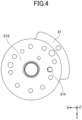
- FIG. 4 is a plan view of the lower head 31 of the rotary compressor 1, which is an example of the rotary compressor according to the present embodiment.
- the head 31 has a through hole 31h extending along the Y-axis direction and from partway extending along the Z-axis direction.
- An intake pipe 12 is connected to one end of the through hole 31h.
- the other end of the through hole 31h is connected to a through hole 41h of the cylinder 41.
- the head 31 has an upper surface 31S.
- a cylinder 41 is placed on the upper surface 31S.
- the piston 61 rotates on the upper surface 31S.
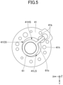
- FIG. 5 is a plan view of the cylinder 41 in the rotary compressor 1, which is an example of the rotary compressor according to the present embodiment.
- FIG. 6 is a bottom view of the cylinder 41 in the rotary compressor 1, which is an example of the rotary compressor according to the present embodiment.
- FIGS. 5 and 6 also illustrate the piston 61 rotating eccentrically inside the cylinder 41.
- the cylinder 41 has a through hole 41h penetrating along the thickness direction, i.e., the Z-axis direction.
- the through hole 41h is provided outside the inner diameter of the cylinder 41.
- One end of the through hole 41h is connected to the through hole 31h of the head 31.
- the other end of the through hole 41h is connected to the through hole 50h of the middle plate 50.
- the cylinder 41 has a groove part 41g which is a groove formed from the through hole 41h to the inside of the cylinder 41.
- the center 41gc of the connection port in the groove part 41g of the cylinder 41 is provided on the blade 61b side of the piston 61 with respect to the line L1 connecting the rotation center 41c of the piston 61 and the center of the through hole 41h.
- FIG. 7 is a plan view of the middle plate 50 in the rotary compressor 1, which is an example of the rotary compressor according to the present embodiment.
- the middle plate 50 has a through hole 50h penetrating along the thickness direction, i.e., the Z-axis direction.
- One end of the through hole 50h is connected to the through hole 41h of the cylinder 41.
- the other end of the through hole 50h is connected to the vertical hole 42h of the cylinder 42.
- FIG. 8 is a plan view of the cylinder 42 in the rotary compressor 1, which is an example of the rotary compressor according to the present embodiment.
- FIG. 9 is a bottom view of the cylinder 42 in the rotary compressor 1, which is an example of the rotary compressor according to the present embodiment.
- FIGS. 8 and 9 also illustrate the piston 62 rotating eccentrically inside the cylinder 42.
- the cylinder 42 has a vertical hole 42h formed along the thickness direction, i.e., the Z-axis direction, to the middle of the thickness of the cylinder 42.
- the vertical hole 42h is provided outside the inner diameter of the cylinder 42.
- the vertical hole 42h is connected to the through hole 50h of the middle plate 50.
- the cylinder 42 has a groove part 42g which is a groove formed from the vertical hole 42h to the inside of the cylinder 42.
- the center 42gc of the connection port in the groove part 42g of the cylinder 42 is provided on the blade 62b side of the piston 62 with respect to a line L2 connecting the rotational center 42c of the piston 62 and the center of the vertical hole 42h.
- the head 32 holds the head 31, the cylinder 41, the middle plate 50 and the cylinder 42.
- the head 32 is fixed to the container 11.
- the head 32 is fixed to the container 11 by welding.
- the lower part of the accumulator 20 is provided below the head 32.
- the piston 61 rotates eccentrically inside the cylinder 41.
- the piston 61 has a blade 61b that divides the compression chamber 41CS of the cylinder 41 into a high-pressure chamber 41HS and a low-pressure chamber 41LS.
- the blade 61b is fixed to the cylinder 41 by a bush 41b.
- the piston 62 rotates eccentrically inside the cylinder 42.
- the piston 62 has a blade 62b that divides a compression chamber 42CS of the cylinder 42 into a high-pressure chamber 42HS and a low-pressure chamber 42LS.
- the blade 62b is fixed to the cylinder 42 by a bush 42b.
- the rotary compressor 1 includes a main flow path MFP which penetrates from the intake pipe 12 to the cylinder 42 through the head 31, the cylinder 41, and the middle plate 50, by a through hole 31h, a through hole 41h, a through hole 50h, and a vertical hole 42h.
- the flow path area SM is the area of a cross section cut at a plane parallel to the YZ plane in a portion extending in the X axis direction of the through hole 41h or the area of a cross section cut at a plane parallel to the XY plane in a portion extending in the Y axis direction of the through hole 41h.
- the rotary compressor 1 includes a branch flow path SFP1 that branches from the main flow path MFP to the inside of the cylinder 41 by the groove part 41g.
- the rotary compressor 1 also includes a branch flow path SFP2 that branches from the main flow path MFP to the inside of the cylinder 42 by the groove part 42g.
- the flow path area SS2 in the branch flow path SFP2 may be different from the flow path area SS1 in the branch flow path SFP1.
- the flow path area SS1 in the branch flow path SFP1 and the flow path area SS2 in the branch flow path SFP2 may be determined so as to optimize the flow rate of refrigerant in the branch flow path SFP1 and the flow rate of refrigerant in the branch flow path SFP2.
- the flow path area SS1 in the branch flow path SFP1 and the flow path area SS2 in the branch flow path SFP2 may be determined so that the flow rate of refrigerant in the branch flow path SFP1 and the flow rate of refrigerant in the branch flow path SFP2 are equal.
- the sum of the flow path area SS1 in the branch flow path SFP1 and the flow path area SS2 in the branch flow path SFP2 may be greater than or equal to the flow path area SM in the main flow path MFP.
- the flow path area SS1 in the branch flow path SFP1 is the area of the cross section of the groove part 41g cut at a plane perpendicular to the direction in which the groove part 41g extends.
- the flow path area SS2 in the branch flow path SFP2 is the area of the cross section of the groove part 42g cut at a plane perpendicular to the direction in which the groove part 42g extends.
- the cylinder 41 is supplied with the refrigerant that has passed through the branch flow path SFP1 branched from the main flow path MFP.
- the cylinder 41 cannot be made thinner than the outer diameter of the intake pipe 12. Because the refrigerant from the intake pipe 12 is supplied to the cylinder 41 through the main flow path MFP and the branch flow path SFP1, the cylinder 41 can be made thinner. Similarly, because the refrigerant from the intake pipe 12 is supplied through the main flow path MFP and the branch flow path SFP2 to the cylinder 42, the cylinder 42 can be made thinner.
- the middle plate 50 cannot be made thinner than the outer diameter of the intake pipe 12. Because the intake pipe 12 is not connected to the middle plate 50, the middle plate 50 can be made thinner.
- the cylinder 41 is an example of a first cylinder
- the cylinder 42 is an example of a second cylinder
- the branch flow path SFP1 is an example of a first branch flow path
- the branch flow path SFP2 is an example of a second branch flow path.
- the compression mechanism can be flattened by thinning the first cylinder, the second cylinder, and the middle plate.
- the main shaft can be shortened by flattening the compression mechanism.
- the influence of shaft deflection of the main shaft can be reduced by shortening the main shaft.
- a suction hole in the cylinder can be designed regardless of the shape of the cylinder.
- the suction hole in the cylinder can be designed regardless of the shape of the cylinder, the degree of freedom of design can be increased.
- the number of parts around the suction part can be reduced. According to the 2-cylinder rotary compressor according to the present embodiment, the number of parts around the suction part can be reduced, thereby reducing the manufacturing cost.
- pressure loss of refrigerant in the 2-cylinder rotary compressor can be reduced by making the flow path area of the main flow path greater than or equal to the flow path area of the suction port to which the intake pipe is connected.
- the amount of refrigerant distributed to the first cylinder and the second cylinder can be optimized because the flow path area of the second branch flow path is different from the flow path area of the first branch flow path.
- pressure loss of refrigerant in the 2-cylinder rotary compressor can be reduced by making the sum of the flow path area of the first branch flow path and the flow path area of the second branch flow path greater than or equal to the flow path area of the main flow path.
- the center of the first connection port in the first branch flow path is provided on the first blade side with respect to the line connecting the main flow path and the rotational center of the first piston, so that the first connection port can be closed quickly. That is, according to the 2-cylinder rotary compressor according to the present embodiment, the angle at which the first connection port is closed can be reduced.
- the center of the second connection port in the second branch flow path is provided on the second blade side with respect to the line connecting the main flow path and the rotational center of the second piston, the second connection port can be closed earlier. That is, according to the 2-cylinder rotary compressor according to the present embodiment, the angle at which the second connection port is closed can be reduced.
- the lower part of the accumulator is provided below the holding member, thereby lowering the center of gravity. According to the 2-cylinder rotary compressor according to the present embodiment, vibration can be reduced by lowering the center of gravity of the 2-cylinder rotary compressor.
- the design freedom of the shape in the suction part of the cylinder can be increased by forming the main flow path with a through-hole and a vertical hole and forming the branch flow path with a groove part.
- the machining in the suction part of the cylinder can be simplified by forming the branch flow path with a groove.
- the machining in the suction part of the cylinder can be simplified, thereby reducing the manufacturing cost.
Landscapes
- Engineering & Computer Science (AREA)
- Mechanical Engineering (AREA)
- General Engineering & Computer Science (AREA)
- Applications Or Details Of Rotary Compressors (AREA)
Abstract
Description
- The present disclosure relates to a 2-cylinder rotary compressor.
-
Patent Document 1 discloses a 2-cylinder rotary compressor having a compression mechanism part and a rotary drive part.Patent Document 1 discloses that the working gas is guided into both cylinder chambers through two intake paths branched at a branch part provided in the partition plate from a single intake pipe connected to the partition plate. - Patent document 1:
Japanese Patent No. 5070097 - In a rotary compressor, flattening of a compression mechanism is required to improve performance.
- The present disclosure provides a technique for flattening a compression mechanism in a 2-cylinder rotary compressor.
- A 2-cylinder rotary compressor of a first aspect includes:
- a head to which an intake pipe is connected;
- a first cylinder in which a first piston rotates eccentrically inside;
- a second cylinder in which a second piston rotates eccentrically inside;
- a middle plate provided between the first cylinder and the second cylinder;
- a main flow path penetrating from the intake pipe through the head, the first cylinder, and the middle plate to the second cylinder;
- a first branch flow path branching from the main flow path into an interior of the first cylinder; and
- a second branch flow path branching from the main flow path into an interior of the second cylinder.
- According to the 2-cylinder rotary compressor of
aspect 1, the compression mechanism can be flattened. - The 2-cylinder rotary compressor according to
aspect 1, wherein a flow path area of the main flow path is greater than or equal to a flow path area of the intake port to which the intake pipe is connected. - The 2-cylinder rotary compressor according to
aspect 1 or 2, wherein a flow path area of the second branch flow path is different from a flow path area of the first branch flow path. - The 2-cylinder rotary compressor according to any one of
aspects 1 to 3, wherein a sum of a flow path area of the first branch flow path and a flow path area of the second branch flow path is greater than or equal to a flow path area of the main flow path. - The 2-cylinder rotary compressor according to any one of
aspects 1 to 4, wherein - the first piston further includes a first blade dividing a first compression chamber formed between the first cylinder and the first piston into a first high-pressure chamber and a first low-pressure chamber,
- a center of a first connection port through which the first branch flow path is connected to the first low-pressure chamber is provided on a side of the first blade with respect to a line connecting the main flow path and a rotation center of the first piston,
- the second piston further includes a second blade dividing a second compression chamber formed between the second cylinder and the second piston into a second high-pressure chamber and a second low-pressure chamber, and
- a center of a second connection port through which the second branch flow path is connected to the second low-pressure chamber is provided on a side of the second blade with respect to a line connecting the main flow path and a rotation center of the second piston.
- The 2-cylinder rotary compressor according to any one of
aspects 1 to 5, further including: - a holding member configured to hold the head, the first cylinder, the middle plate, and the second cylinder;
- a container configured to house the head, the first cylinder, the middle plate, the second cylinder, and the holding member inside; and
- an accumulator connected to the intake pipe, wherein
- the holding member is fixed to the container, and
- a lower portion of the accumulator is provided below the holding member.
- The 2-cylinder rotary compressor according to any one of
aspects 1 to 6, wherein a refrigerant used is carbon dioxide. - The 2-cylinder rotary compressor according to any one of
aspects 1 to 7, wherein - the first cylinder includes
- a first through-hole that penetrates outside an inner diameter of the first cylinder in a thickness direction, and
- a first groove part formed from the first through-hole to inside the first cylinder, wherein
- the middle plate includes a second through-hole penetrating in a thickness direction,
- the second cylinder includes
- a vertical hole extending in a thickness direction outside an inner diameter of the second cylinder, and
- a second groove part formed from the vertical hole to inside the second cylinder, wherein
- the first through-hole, the second through-hole, and the vertical hole each form a part of the main flow path,
- the first groove part forms the first branch flow path, and
- the second groove part forms the second branch flow path.
-
- [
FIG. 1] FIG. 1 is a perspective view of a rotary compressor according to the present embodiment. - [
FIG. 2] FIG. 2 is a cross-sectional view of a rotary compressor according to the present embodiment. - [
FIG. 3] FIG. 3 is an enlarged cross-sectional view of a rotary compressor according to the present embodiment. - [
FIG. 4] FIG. 4 is a plan view of a head in a rotary compressor according to the present embodiment. - [
FIG. 5] FIG. 5 is a plan view of a cylinder in a rotary compressor according to the present embodiment. - [
FIG. 6] FIG. 6 is a bottom view of a cylinder in a rotary compressor according to the present embodiment. - [
FIG. 7] FIG. 7 is a plan view of a middle plate in a rotary compressor according to the present embodiment. - [
FIG. 8] FIG. 8 is a plan view of a cylinder in a rotary compressor according to the present embodiment. - [
FIG. 9] FIG. 9 is a bottom view of a cylinder in a rotary compressor according to the present embodiment. - Specific examples of the rotary compressor of the present disclosure will be described below with reference to the drawings. Note that the present disclosure is not limited to these examples, but is intended to be indicated by the claims and to include all changes within the meaning and scope equivalent to the claims.
- Note that, in the description in the specification and drawings of each embodiment, with respect to components having substantially the same or corresponding functional configuration, overlapping descriptions may be omitted by assigning the same reference numerals. Further, in order to facilitate understanding, the scale of each part in the drawings may differ from the actual scale.
- In the directions such as parallel, right angle, orthogonal, horizontal, vertical, up and down, left and right, front and back, etc., misalignments are permitted as long as the effect of the embodiment is not impaired. The shape of the corners is not limited to right angles and may be rounded. Parallel, right angle, orthogonal, horizontal, and vertical may include substantially parallel, substantially right angle, substantially orthogonal, substantially horizontal, and substantially vertical, respectively.
- For example, substantially parallel means that even if two lines or two surfaces are not perfectly parallel to each other, they can be treated as parallel to each other within the limits permitted by manufacturing. It is intended that each of the other positional relationships of lines or surfaces, that is, substantially perpendicular, substantially orthogonal, substantially horizontal, and substantially vertical lines or surfaces fall within the manufacturing permissible range, similar to substantially parallel lines or surfaces.
- A rotary compressor according to the present embodiment will be described below. The rotary compressor according to the present embodiment includes a head to which an intake pipe is connected, a first cylinder in which the first piston rotates eccentrically inside, a second cylinder in which the second piston rotates eccentrically inside, and a middle plate provided between the first cylinder and the second cylinder. The rotary compressor according to the present embodiment includes a main flow path penetrating from the intake pipe to the second cylinder through the head, the first cylinder, and the middle plate. The rotary compressor according to the present embodiment includes a first branch flow path branching from the main flow path into the interior of the first cylinder, and a second branch flow path branching from the main flow path into the interior of the second cylinder.
- A rotary device according to the present embodiment will be described using a
rotary compressor 1 which is an example of a rotary device according to the present embodiment.FIG. 1 is a perspective view of therotary compressor 1 which is an example of a rotary compressor according to the present embodiment.FIG. 2 is a cross-sectional view of therotary compressor 1 which is an example of a rotary compressor according to the present embodiment.FIG. 3 is an enlarged cross-sectional view of therotary compressor 1 which is an example of a rotary compressor according to the present embodiment. - For the convenience of explanation, a virtual three-dimensional coordinate system (XYZ orthogonal coordinate system) consisting of the X-axis, Y-axis, and Z-axis (XYZ axis) orthogonal to each other may be set in the drawing. For example, when a black circle is illustrated in the circle of the coordinate axis perpendicular to the paper plane of the drawing, this indicates that the coordinate axis is facing toward the front side with respect to the paper plane. When a cross is illustrated in the circle of the coordinate axis, this indicates that the coordinate axis is facing toward the back side with respect to the paper plane.
- However, this coordinate system is provided for the purpose of explanation and does not limit the attitude of the rotary compressor, etc., according to the present embodiment.
- In the following drawings, the piston of the rotary compressor rotates in the XY plane which is a plane parallel to the X-axis direction and the Y-axis direction.
- A plan view is a drawing in which an object is viewed from the +Z side in the opposite direction of the Z axis along the Z axis direction. Viewing in plan view refers to viewing an object from the +Z side in the opposite direction of the Z axis along the Z axis direction. A bottom view is a drawing in which an object is viewed from the -Z side in the Z axis direction along the Z axis direction. Viewing in bottom view refers to viewing an object from the -Z side in the Z axis direction along the Z axis direction.
- The
rotary compressor 1 compresses a refrigerant. The refrigerant used in therotary compressor 1 is, for example, carbon dioxide. The refrigerant is not limited to carbon dioxide, but may be, for example, a fluorocarbon-based refrigerant. Therotary compressor 1 includes acompressor body 10 and anaccumulator 20. - The
compressor body 10 includes acontainer 11, anintake pipe 12, anoutlet pipe 13, and apower terminal 15. Thecontainer 11 also includes aplate 14 for installing thecompressor body 10. - The
compressor body 10 includes acompression part 70 and an electrically drivenpart 80 provided inside. The electrically drivenpart 80 rotates amain shaft 81. Thecompression part 70 compresses the refrigerant supplied from theintake pipe 12. The refrigerant compressed in thecompression part 70 is discharged from theoutlet pipe 13 to the outside of therotary compressor 1. Thecompression part 70 constitutes a compression mechanism. - The electrically driven
part 80 rotates themain shaft 81. In thecompression part 70, themain shaft 81 rotated by the electrically drivenpart 80 rotates each of apiston 61 and apiston 62. Each of thepiston 61 and thepiston 62 rotates eccentrically when themain shaft 81 rotates. As each of thepiston 61 and thepiston 62 rotates, the refrigerant is compressed in thecompression part 70. - The
compression part 70 includes ahead 31, acylinder 41, amiddle plate 50, acylinder 42, and ahead 32. Thehead 31, thecylinder 41, themiddle plate 50, thecylinder 42, and thehead 32 are stacked sequentially from the bottom. Themain shaft 81 penetrates each of thehead 31, thecylinder 41, themiddle plate 50, thecylinder 42, and thehead 32. - The
compression part 70 is provided with thepiston 61 eccentrically rotated by themain shaft 81, inside thecylinder 41. Thecompression part 70 is provided with thepiston 62 eccentrically rotated by themain shaft 81, inside thecylinder 42. - The
head 31 will be described below.FIG. 4 is a plan view of thelower head 31 of therotary compressor 1, which is an example of the rotary compressor according to the present embodiment. - The
head 31 has a throughhole 31h extending along the Y-axis direction and from partway extending along the Z-axis direction. Anintake pipe 12 is connected to one end of the throughhole 31h. The other end of the throughhole 31h is connected to a throughhole 41h of thecylinder 41. - The
head 31 has anupper surface 31S. Acylinder 41 is placed on theupper surface 31S. Thepiston 61 rotates on theupper surface 31S. - Next, the
cylinder 41 will be described.FIG. 5 is a plan view of thecylinder 41 in therotary compressor 1, which is an example of the rotary compressor according to the present embodiment.FIG. 6 is a bottom view of thecylinder 41 in therotary compressor 1, which is an example of the rotary compressor according to the present embodiment.FIGS. 5 and6 also illustrate thepiston 61 rotating eccentrically inside thecylinder 41. - The
cylinder 41 has a throughhole 41h penetrating along the thickness direction, i.e., the Z-axis direction. The throughhole 41h is provided outside the inner diameter of thecylinder 41. One end of the throughhole 41h is connected to the throughhole 31h of thehead 31. The other end of the throughhole 41h is connected to the throughhole 50h of themiddle plate 50. Thecylinder 41 has agroove part 41g which is a groove formed from the throughhole 41h to the inside of thecylinder 41. - The center 41gc of the connection port in the
groove part 41g of thecylinder 41 is provided on theblade 61b side of thepiston 61 with respect to the line L1 connecting therotation center 41c of thepiston 61 and the center of the throughhole 41h. - Next, the
middle plate 50 will be described.FIG. 7 is a plan view of themiddle plate 50 in therotary compressor 1, which is an example of the rotary compressor according to the present embodiment. - The
middle plate 50 has a throughhole 50h penetrating along the thickness direction, i.e., the Z-axis direction. One end of the throughhole 50h is connected to the throughhole 41h of thecylinder 41. The other end of the throughhole 50h is connected to thevertical hole 42h of thecylinder 42. - Next, the
cylinder 42 will be described.FIG. 8 is a plan view of thecylinder 42 in therotary compressor 1, which is an example of the rotary compressor according to the present embodiment.FIG. 9 is a bottom view of thecylinder 42 in therotary compressor 1, which is an example of the rotary compressor according to the present embodiment.FIGS. 8 and9 also illustrate thepiston 62 rotating eccentrically inside thecylinder 42. - The
cylinder 42 has avertical hole 42h formed along the thickness direction, i.e., the Z-axis direction, to the middle of the thickness of thecylinder 42. Thevertical hole 42h is provided outside the inner diameter of thecylinder 42. Thevertical hole 42h is connected to the throughhole 50h of themiddle plate 50. Thecylinder 42 has agroove part 42g which is a groove formed from thevertical hole 42h to the inside of thecylinder 42. - The center 42gc of the connection port in the
groove part 42g of thecylinder 42 is provided on theblade 62b side of thepiston 62 with respect to a line L2 connecting therotational center 42c of thepiston 62 and the center of thevertical hole 42h. - The
head 32 holds thehead 31, thecylinder 41, themiddle plate 50 and thecylinder 42. Thehead 32 is fixed to thecontainer 11. For example, thehead 32 is fixed to thecontainer 11 by welding. The lower part of theaccumulator 20 is provided below thehead 32. - The
piston 61 rotates eccentrically inside thecylinder 41. Thepiston 61 has ablade 61b that divides the compression chamber 41CS of thecylinder 41 into a high-pressure chamber 41HS and a low-pressure chamber 41LS. Theblade 61b is fixed to thecylinder 41 by abush 41b. - The
piston 62 rotates eccentrically inside thecylinder 42. Thepiston 62 has ablade 62b that divides a compression chamber 42CS of thecylinder 42 into a high-pressure chamber 42HS and a low-pressure chamber 42LS. Theblade 62b is fixed to thecylinder 42 by abush 42b. - As illustrated in
FIG. 3 , therotary compressor 1 includes a main flow path MFP which penetrates from theintake pipe 12 to thecylinder 42 through thehead 31, thecylinder 41, and themiddle plate 50, by a throughhole 31h, a throughhole 41h, a throughhole 50h, and avertical hole 42h. - The flow path area SM in the main flow path MFP may be greater than or equal to the flow path area SSC at the intake port to which the
intake pipe 12 is connected. In the present disclosure, the flow path area is the area of the cross section of the flow path cut at a plane perpendicular to the direction in which the refrigerant flows. For example, the flow path area SM is the area of a cross section cut at a plane parallel to the XY plane in the throughhole 41h, the throughhole 50h, and thevertical hole 42h. The flow path area SM is the area of a cross section cut at a plane parallel to the YZ plane in a portion extending in the X axis direction of the throughhole 41h or the area of a cross section cut at a plane parallel to the XY plane in a portion extending in the Y axis direction of the throughhole 41h. - As illustrated in
FIG. 3 , therotary compressor 1 includes a branch flow path SFP1 that branches from the main flow path MFP to the inside of thecylinder 41 by thegroove part 41g. Therotary compressor 1 also includes a branch flow path SFP2 that branches from the main flow path MFP to the inside of thecylinder 42 by thegroove part 42g. - The flow path area SS2 in the branch flow path SFP2 may be different from the flow path area SS1 in the branch flow path SFP1. For example, the flow path area SS1 in the branch flow path SFP1 and the flow path area SS2 in the branch flow path SFP2 may be determined so as to optimize the flow rate of refrigerant in the branch flow path SFP1 and the flow rate of refrigerant in the branch flow path SFP2. For example, the flow path area SS1 in the branch flow path SFP1 and the flow path area SS2 in the branch flow path SFP2 may be determined so that the flow rate of refrigerant in the branch flow path SFP1 and the flow rate of refrigerant in the branch flow path SFP2 are equal.
- The sum of the flow path area SS1 in the branch flow path SFP1 and the flow path area SS2 in the branch flow path SFP2 may be greater than or equal to the flow path area SM in the main flow path MFP. By making the sum of the flow path area SS1 in the branch flow path SFP1 and the flow path area SS2 in the branch flow path SFP2 to be greater than or equal to the flow path area SM in the main flow path MFP, pressure loss in the branch flow path SFP1 and the branch flow path SFP2 can be reduced.
- The flow path area SS1 in the branch flow path SFP1 is the area of the cross section of the
groove part 41g cut at a plane perpendicular to the direction in which thegroove part 41g extends. The flow path area SS2 in the branch flow path SFP2 is the area of the cross section of thegroove part 42g cut at a plane perpendicular to the direction in which thegroove part 42g extends. - The
cylinder 41 is supplied with the refrigerant that has passed through the branch flow path SFP1 branched from the main flow path MFP. For example, if theintake pipe 12 is directly connected to thecylinder 41, thecylinder 41 cannot be made thinner than the outer diameter of theintake pipe 12. Because the refrigerant from theintake pipe 12 is supplied to thecylinder 41 through the main flow path MFP and the branch flow path SFP1, thecylinder 41 can be made thinner. Similarly, because the refrigerant from theintake pipe 12 is supplied through the main flow path MFP and the branch flow path SFP2 to thecylinder 42, thecylinder 42 can be made thinner. - If the
intake pipe 12 is directly connected to themiddle plate 50, as disclosed inPatent Document 1, for example, themiddle plate 50 cannot be made thinner than the outer diameter of theintake pipe 12. Because theintake pipe 12 is not connected to themiddle plate 50, themiddle plate 50 can be made thinner. - The
cylinder 41 is an example of a first cylinder, thecylinder 42 is an example of a second cylinder, the branch flow path SFP1 is an example of a first branch flow path, and the branch flow path SFP2 is an example of a second branch flow path. - According to the 2-cylinder rotary compressor according to the present embodiment, the compression mechanism can be flattened by thinning the first cylinder, the second cylinder, and the middle plate. According to the 2-cylinder rotary compressor according to the present embodiment, the main shaft can be shortened by flattening the compression mechanism. According to the 2-cylinder rotary compressor according to the present embodiment, the influence of shaft deflection of the main shaft can be reduced by shortening the main shaft.
- Moreover, according to the 2-cylinder rotary compressor according to the present embodiment, because the intake pipe is connected to the head, a suction hole in the cylinder can be designed regardless of the shape of the cylinder. According to the 2-cylinder rotary compressor according to the present embodiment, because the suction hole in the cylinder can be designed regardless of the shape of the cylinder, the degree of freedom of design can be increased.
- Furthermore, according to the 2-cylinder rotary compressor according to the present embodiment, the number of parts around the suction part can be reduced. According to the 2-cylinder rotary compressor according to the present embodiment, the number of parts around the suction part can be reduced, thereby reducing the manufacturing cost.
- According to the 2-cylinder rotary compressor according to the present embodiment, pressure loss of refrigerant in the 2-cylinder rotary compressor can be reduced by making the flow path area of the main flow path greater than or equal to the flow path area of the suction port to which the intake pipe is connected.
- According to the 2-cylinder rotary compressor according to the present embodiment, the amount of refrigerant distributed to the first cylinder and the second cylinder can be optimized because the flow path area of the second branch flow path is different from the flow path area of the first branch flow path.
- According to the 2-cylinder rotary compressor according to the present embodiment, pressure loss of refrigerant in the 2-cylinder rotary compressor can be reduced by making the sum of the flow path area of the first branch flow path and the flow path area of the second branch flow path greater than or equal to the flow path area of the main flow path.
- According to the 2-cylinder rotary compressor according to the present embodiment, the center of the first connection port in the first branch flow path is provided on the first blade side with respect to the line connecting the main flow path and the rotational center of the first piston, so that the first connection port can be closed quickly. That is, according to the 2-cylinder rotary compressor according to the present embodiment, the angle at which the first connection port is closed can be reduced. Similarly, according to the 2-cylinder rotary compressor according to the present embodiment, because the center of the second connection port in the second branch flow path is provided on the second blade side with respect to the line connecting the main flow path and the rotational center of the second piston, the second connection port can be closed earlier. That is, according to the 2-cylinder rotary compressor according to the present embodiment, the angle at which the second connection port is closed can be reduced.
- According to the 2-cylinder rotary compressor according to the present embodiment, the lower part of the accumulator is provided below the holding member, thereby lowering the center of gravity. According to the 2-cylinder rotary compressor according to the present embodiment, vibration can be reduced by lowering the center of gravity of the 2-cylinder rotary compressor.
- According to the 2-cylinder rotary compressor according to the present embodiment, the design freedom of the shape in the suction part of the cylinder can be increased by forming the main flow path with a through-hole and a vertical hole and forming the branch flow path with a groove part. Moreover, according to the 2-cylinder rotary compressor according to the present embodiment, the machining in the suction part of the cylinder can be simplified by forming the branch flow path with a groove. According to the 2-cylinder rotary compressor according to the present embodiment, the machining in the suction part of the cylinder can be simplified, thereby reducing the manufacturing cost.
- Although the embodiment has been described above, it will be understood that various changes in form and details can be made without departing from the purpose and scope of the claims. Various variations and improvements such as combinations and substitutions with some or all of the other embodiments can be made.
- The present international application is based upon and claims priority to
Japanese patent application no. 2023-057481 filed on March 31, 2023 -
- 1 rotary compressor
- 10 compressor body
- 11 container
- 12 intake pipe
- 13 outlet pipe
- 20 accumulator
- 31 head
- 31h through-hole
- 32 head
- 41, 42 cylinder
- 41b, 42b bush
- 41c, 42c rotation center
- 41g, 42g groove part
- 41gc, 42gc center
- 41h through-hole
- 42h vertical hole
- 41CS, 42CS compression chamber
- 41HS, 42HS high-pressure chamber
- 41LS, 42LS low-pressure chamber
- 50 middle plate
- 50h through-hole
- 61, 62 piston
- 61b, 62b blade
- 70 compression part
- 80 electrically driven part
- 81 main shaft
- MFP main flow path
- SFP1, SFP2 branch flow path
- SM, SS1, SS2, SSC flow path area
Claims (8)
- A 2-cylinder rotary compressor comprising:a head to which an intake pipe is connected;a first cylinder in which a first piston rotates eccentrically inside;a second cylinder in which a second piston rotates eccentrically inside;a middle plate provided between the first cylinder and the second cylinder;a main flow path penetrating from the intake pipe through the head, the first cylinder, and the middle plate to the second cylinder;a first branch flow path branching from the main flow path into an interior of the first cylinder; anda second branch flow path branching from the main flow path into an interior of the second cylinder.
- The 2-cylinder rotary compressor according to claim 1, wherein a flow path area of the main flow path is greater than or equal to a flow path area of the intake port to which the intake pipe is connected.
- The 2-cylinder rotary compressor according to claim 1 or 2, wherein a flow path area of the second branch flow path is different from a flow path area of the first branch flow path.
- The 2-cylinder rotary compressor according to any one of claims 1 to 3, wherein a sum of a flow path area of the first branch flow path and a flow path area of the second branch flow path is greater than or equal to a flow path area of the main flow path.
- The 2-cylinder rotary compressor according to any one of claims 1 to 4, whereinthe first piston further includes a first blade dividing a first compression chamber formed between the first cylinder and the first piston into a first high-pressure chamber and a first low-pressure chamber,a center of a first connection port through which the first branch flow path is connected to the first low-pressure chamber is provided on a side of the first blade with respect to a line connecting the main flow path and a rotation center of the first piston,the second piston further includes a second blade dividing a second compression chamber formed between the second cylinder and the second piston into a second high-pressure chamber and a second low-pressure chamber, anda center of a second connection port through which the second branch flow path is connected to the second low-pressure chamber is provided on a side of the second blade with respect to a line connecting the main flow path and a rotation center of the second piston.
- The 2-cylinder rotary compressor according to any one of claims 1 to 5, further comprising:a holding member configured to hold the head, the first cylinder, the middle plate, and the second cylinder;a container configured to house the head, the first cylinder, the middle plate, the second cylinder, and the holding member inside; andan accumulator connected to the intake pipe, whereinthe holding member is fixed to the container, anda lower portion of the accumulator is provided below the holding member.
- The 2-cylinder rotary compressor according to any one of claims 1 to 6, wherein a refrigerant used is carbon dioxide.
- The 2-cylinder rotary compressor according to any one of claims 1 to 7, whereinthe first cylinder includesa first through-hole that penetrates outside an inner diameter of the first cylinder in a thickness direction, anda first groove part formed from the first through-hole to inside the first cylinder, whereinthe middle plate includes a second through-hole penetrating in a thickness direction,the second cylinder includesa vertical hole extending in a thickness direction outside an inner diameter of the second cylinder, anda second groove part formed from the vertical hole to inside the second cylinder, whereinthe first through-hole, the second through-hole, and the vertical hole each form a part of the main flow path,the first groove part forms the first branch flow path, andthe second groove part forms the second branch flow path.
Applications Claiming Priority (2)
| Application Number | Priority Date | Filing Date | Title |
|---|---|---|---|
| JP2023057481A JP7662954B2 (en) | 2023-03-31 | 2023-03-31 | 2 cylinder rotary compressor |
| PCT/JP2024/009488 WO2024203268A1 (en) | 2023-03-31 | 2024-03-12 | Two-cylinder rotary compressor |
Publications (2)
| Publication Number | Publication Date |
|---|---|
| EP4542046A1 true EP4542046A1 (en) | 2025-04-23 |
| EP4542046A4 EP4542046A4 (en) | 2025-08-20 |
Family
ID=92904648
Family Applications (1)
| Application Number | Title | Priority Date | Filing Date |
|---|---|---|---|
| EP24779398.7A Pending EP4542046A4 (en) | 2023-03-31 | 2024-03-12 | TWO-CYLINDER ROTARY COMPRESSOR |
Country Status (5)
| Country | Link |
|---|---|
| US (1) | US20260016010A1 (en) |
| EP (1) | EP4542046A4 (en) |
| JP (2) | JP7662954B2 (en) |
| CN (2) | CN122191080A (en) |
| WO (1) | WO2024203268A1 (en) |
Family Cites Families (12)
| Publication number | Priority date | Publication date | Assignee | Title |
|---|---|---|---|---|
| JP2005207306A (en) * | 2004-01-22 | 2005-08-04 | Mitsubishi Electric Corp | 2-cylinder rotary compressor |
| JP5070097B2 (en) | 2007-08-28 | 2012-11-07 | 東芝キヤリア株式会社 | Two-cylinder rotary compressor and refrigeration cycle apparatus using the same |
| JP4305550B2 (en) * | 2007-09-28 | 2009-07-29 | ダイキン工業株式会社 | Rotary fluid machine |
| CN101469710A (en) * | 2007-12-25 | 2009-07-01 | 上海日立电器有限公司 | Compressor cylinder |
| JP2010150949A (en) * | 2008-12-24 | 2010-07-08 | Daikin Ind Ltd | Rotary compressor |
| CN202391736U (en) * | 2011-12-09 | 2012-08-22 | 广东美芝制冷设备有限公司 | Multi-cylinder rotary compressor and refrigeration circulation system thereof |
| EP3249230B1 (en) * | 2015-01-13 | 2019-08-21 | Fujitsu General Limited | Rotary compressor |
| JP6787480B2 (en) * | 2017-03-17 | 2020-11-18 | ダイキン工業株式会社 | Rotary compressor |
| JP2020084822A (en) * | 2018-11-19 | 2020-06-04 | ダイキン工業株式会社 | Rotary compressor |
| EP3951181B8 (en) * | 2019-04-25 | 2025-11-05 | Mitsubishi Heavy Industries Thermal Systems, Ltd. | Rotary compressor |
| JP2022174441A (en) * | 2021-05-11 | 2022-11-24 | パナソニックIpマネジメント株式会社 | Rotary compressor and refrigeration cycle equipment |
| JP7680930B2 (en) | 2021-10-11 | 2025-05-21 | 日本信号株式会社 | Information provision system |
-
2023
- 2023-03-31 JP JP2023057481A patent/JP7662954B2/en active Active
-
2024
- 2024-03-12 WO PCT/JP2024/009488 patent/WO2024203268A1/en not_active Ceased
- 2024-03-12 CN CN202610568957.9A patent/CN122191080A/en active Pending
- 2024-03-12 EP EP24779398.7A patent/EP4542046A4/en active Pending
- 2024-03-12 CN CN202480020386.4A patent/CN120958239B/en active Active
- 2024-06-05 JP JP2024091615A patent/JP2024146947A/en active Pending
-
2025
- 2025-09-18 US US19/332,639 patent/US20260016010A1/en active Pending
Also Published As
| Publication number | Publication date |
|---|---|
| JP2024145222A (en) | 2024-10-15 |
| JP2024146947A (en) | 2024-10-15 |
| WO2024203268A1 (en) | 2024-10-03 |
| EP4542046A4 (en) | 2025-08-20 |
| CN120958239A (en) | 2025-11-14 |
| JP7662954B2 (en) | 2025-04-16 |
| CN120958239B (en) | 2026-05-15 |
| CN122191080A (en) | 2026-06-12 |
| US20260016010A1 (en) | 2026-01-15 |
Similar Documents
| Publication | Publication Date | Title |
|---|---|---|
| KR101375979B1 (en) | Rotary compressor | |
| JP4877054B2 (en) | Rotary compressor | |
| CN107859624B (en) | Compressor and air conditioner with same | |
| EP3995696B1 (en) | Hermetic compressor | |
| JPS61126395A (en) | 2-cylinder type rotary compressor | |
| EP3214312A1 (en) | Two-cylinder hermetic compressor | |
| CN104302923A (en) | Gas compressor | |
| US10578108B2 (en) | Electric compressor | |
| EP3242023A1 (en) | Linear compressor | |
| US20260016010A1 (en) | 2-cylinder rotary compressor | |
| CN104747450B (en) | Hermetic type compressor | |
| EP3919745B1 (en) | Compressor and refrigeration cycle device | |
| US20220049700A1 (en) | Screw Compressor | |
| CN110220338A (en) | Supporting structure and compressor | |
| CN210829730U (en) | Compressor cylinder, compressor and air conditioner | |
| AU2018352907B2 (en) | Rotating shaft of rotary compressor and rotary compressor | |
| US20190376519A1 (en) | Compressor and vehicle | |
| EP3748164A1 (en) | Scroll fluid machine and method for manufacturing scroll fluid machine | |
| EP3106611A1 (en) | Suction/compression assmebly for a waste material intake equipment or system | |
| CN112460020B (en) | Pump body assembly, rotor compressor and air conditioner | |
| US6322334B1 (en) | Rotary piston system | |
| CN210135086U (en) | Horizontal compressor | |
| KR102302330B1 (en) | Compressor | |
| CN114151347A (en) | Cylinder, pump body structure, compressor and air conditioner | |
| CN114555948A (en) | Compressor and refrigeration cycle device |
Legal Events
| Date | Code | Title | Description |
|---|---|---|---|
| STAA | Information on the status of an ep patent application or granted ep patent |
Free format text: STATUS: THE INTERNATIONAL PUBLICATION HAS BEEN MADE |
|
| PUAI | Public reference made under article 153(3) epc to a published international application that has entered the european phase |
Free format text: ORIGINAL CODE: 0009012 |
|
| STAA | Information on the status of an ep patent application or granted ep patent |
Free format text: STATUS: REQUEST FOR EXAMINATION WAS MADE |
|
| 17P | Request for examination filed |
Effective date: 20250117 |
|
| AK | Designated contracting states |
Kind code of ref document: A1 Designated state(s): AL AT BE BG CH CY CZ DE DK EE ES FI FR GB GR HR HU IE IS IT LI LT LU LV MC ME MK MT NL NO PL PT RO RS SE SI SK SM TR |
|
| REG | Reference to a national code |
Ref country code: DE Ref legal event code: R079 Free format text: PREVIOUS MAIN CLASS: F04C0018356000 Ipc: F04C0018320000 |
|
| A4 | Supplementary search report drawn up and despatched |
Effective date: 20250721 |
|
| RIC1 | Information provided on ipc code assigned before grant |
Ipc: F04C 18/32 20060101AFI20250715BHEP Ipc: F04C 23/00 20060101ALI20250715BHEP Ipc: F04C 29/12 20060101ALI20250715BHEP |
|
| P01 | Opt-out of the competence of the unified patent court (upc) registered |
Free format text: CASE NUMBER: UPC_APP_3794_4542046/2025 Effective date: 20250820 |
|
| GRAP | Despatch of communication of intention to grant a patent |
Free format text: ORIGINAL CODE: EPIDOSNIGR1 |
|
| STAA | Information on the status of an ep patent application or granted ep patent |
Free format text: STATUS: GRANT OF PATENT IS INTENDED |
|
| RIC1 | Information provided on ipc code assigned before grant |
Ipc: F04C 18/32 20060101AFI20260422BHEP Ipc: F04C 23/00 20060101ALI20260422BHEP Ipc: F04C 29/12 20060101ALI20260422BHEP |
|
| DAV | Request for validation of the european patent (deleted) | ||
| DAX | Request for extension of the european patent (deleted) | ||
| INTG | Intention to grant announced |
Effective date: 20260511 |
|
| GRAJ | Information related to disapproval of communication of intention to grant by the applicant or resumption of examination proceedings by the epo deleted |
Free format text: ORIGINAL CODE: EPIDOSDIGR1 |
|
| STAA | Information on the status of an ep patent application or granted ep patent |
Free format text: STATUS: REQUEST FOR EXAMINATION WAS MADE |