EP4542042A1 - Silencer and electric vacuum pump - Google Patents
Silencer and electric vacuum pump Download PDFInfo
- Publication number
- EP4542042A1 EP4542042A1 EP24205211.6A EP24205211A EP4542042A1 EP 4542042 A1 EP4542042 A1 EP 4542042A1 EP 24205211 A EP24205211 A EP 24205211A EP 4542042 A1 EP4542042 A1 EP 4542042A1
- Authority
- EP
- European Patent Office
- Prior art keywords
- silencing
- flow guide
- edge
- silencer
- exhaust
- Prior art date
- Legal status (The legal status is an assumption and is not a legal conclusion. Google has not performed a legal analysis and makes no representation as to the accuracy of the status listed.)
- Granted
Links
Images


Classifications
-
- F—MECHANICAL ENGINEERING; LIGHTING; HEATING; WEAPONS; BLASTING
- F04—POSITIVE - DISPLACEMENT MACHINES FOR LIQUIDS; PUMPS FOR LIQUIDS OR ELASTIC FLUIDS
- F04B—POSITIVE-DISPLACEMENT MACHINES FOR LIQUIDS; PUMPS
- F04B39/00—Component parts, details, or accessories, of pumps or pumping systems specially adapted for elastic fluids, not otherwise provided for in, or of interest apart from, groups F04B25/00 - F04B37/00
- F04B39/0027—Pulsation and noise damping means
- F04B39/0083—Pulsation and noise damping means using blow off silencers
-
- F—MECHANICAL ENGINEERING; LIGHTING; HEATING; WEAPONS; BLASTING
- F04—POSITIVE - DISPLACEMENT MACHINES FOR LIQUIDS; PUMPS FOR LIQUIDS OR ELASTIC FLUIDS
- F04B—POSITIVE-DISPLACEMENT MACHINES FOR LIQUIDS; PUMPS
- F04B53/00—Component parts, details or accessories not provided for in, or of interest apart from, groups F04B1/00 - F04B23/00 or F04B39/00 - F04B47/00
- F04B53/001—Noise damping
-
- F—MECHANICAL ENGINEERING; LIGHTING; HEATING; WEAPONS; BLASTING
- F04—POSITIVE - DISPLACEMENT MACHINES FOR LIQUIDS; PUMPS FOR LIQUIDS OR ELASTIC FLUIDS
- F04B—POSITIVE-DISPLACEMENT MACHINES FOR LIQUIDS; PUMPS
- F04B37/00—Pumps having pertinent characteristics not provided for in, or of interest apart from, groups F04B25/00 - F04B35/00
- F04B37/10—Pumps having pertinent characteristics not provided for in, or of interest apart from, groups F04B25/00 - F04B35/00 for special use
- F04B37/14—Pumps having pertinent characteristics not provided for in, or of interest apart from, groups F04B25/00 - F04B35/00 for special use to obtain high vacuum
-
- F—MECHANICAL ENGINEERING; LIGHTING; HEATING; WEAPONS; BLASTING
- F04—POSITIVE - DISPLACEMENT MACHINES FOR LIQUIDS; PUMPS FOR LIQUIDS OR ELASTIC FLUIDS
- F04B—POSITIVE-DISPLACEMENT MACHINES FOR LIQUIDS; PUMPS
- F04B39/00—Component parts, details, or accessories, of pumps or pumping systems specially adapted for elastic fluids, not otherwise provided for in, or of interest apart from, groups F04B25/00 - F04B37/00
- F04B39/0027—Pulsation and noise damping means
- F04B39/0055—Pulsation and noise damping means with a special shape of fluid passage, e.g. bends, throttles, diameter changes, pipes
-
- F—MECHANICAL ENGINEERING; LIGHTING; HEATING; WEAPONS; BLASTING
- F04—POSITIVE - DISPLACEMENT MACHINES FOR LIQUIDS; PUMPS FOR LIQUIDS OR ELASTIC FLUIDS
- F04C—ROTARY-PISTON, OR OSCILLATING-PISTON, POSITIVE-DISPLACEMENT MACHINES FOR LIQUIDS; ROTARY-PISTON, OR OSCILLATING-PISTON, POSITIVE-DISPLACEMENT PUMPS
- F04C29/00—Component parts, details or accessories of pumps or pumping installations, not provided for in groups F04C18/00 - F04C28/00
- F04C29/06—Silencing
-
- F—MECHANICAL ENGINEERING; LIGHTING; HEATING; WEAPONS; BLASTING
- F04—POSITIVE - DISPLACEMENT MACHINES FOR LIQUIDS; PUMPS FOR LIQUIDS OR ELASTIC FLUIDS
- F04C—ROTARY-PISTON, OR OSCILLATING-PISTON, POSITIVE-DISPLACEMENT MACHINES FOR LIQUIDS; ROTARY-PISTON, OR OSCILLATING-PISTON, POSITIVE-DISPLACEMENT PUMPS
- F04C29/00—Component parts, details or accessories of pumps or pumping installations, not provided for in groups F04C18/00 - F04C28/00
- F04C29/06—Silencing
- F04C29/065—Noise dampening volumes, e.g. muffler chambers
Definitions
- the present invention relates to the technical field of silencing, and in particular, to a silencer and an electric vacuum pump.
- silencers can be used to reduce the noise level.
- a silencer is usually provided at an exhaust port of an electric vacuum pump of a vehicle to reduce noise.
- the present invention provides a silencer, which can effectively reduce the noise level by means of a three-dimensional maze silencing path.
- the silencer according to the present invention is assembled to an electric vacuum pump, the noise, vibration and harshness (NVH) problem of the electric vacuum pump can be effectively solved.
- An aspect of the present invention provides a silencer, including: first silencing members and second silencing members, which are alternately stacked, each first silencing member being provided with dispersed first flow guide channels, and each second silencing member being provided with gathered second flow guide channels; and an exhaust member provided with an exhaust hole, an edge of the exhaust member being connected to an edge of each silencing member, and the silencer forming a three-dimensional maze silencing path leading to the exhaust hole from an intake port through the alternating first flow guide channels and second flow guide channels.
- the first flow guide channel includes: a first flow guide surface, a downstream of the first flow guide surface being distributed at the edge of the first silencing member; an intake cavity provided upstream of the first flow guide surface; and notches distributed in a side wall of the intake cavity.
- the second flow guide channel includes: a second flow guide surface, an upstream of the second flow guide surface being distributed at the edge of the second silencing member; and a vent hole provided downstream of the second flow guide surface and aligned with the adjacent intake cavity.
- each second silencing member is provided with a first flange; and the edge of each first silencing member is in clearance fit with a corresponding first flange, the edge of the exhaust member is in sealing fit with a corresponding first flange, and the first flanges are in sealing fit with each other.
- each first silencing member is connected to the corresponding first flange via a snap-fit member
- the edge of the exhaust member is connected to the corresponding first flange via a guide pin
- the first flanges are connected to each other via the guide pin.
- the first silencing member is made of a porous material, and the first flow guide channel includes pores dispersed in the porous material; and the second flow guide channel includes pores provided in a central area or a corner area of the second silencing member in a centralized manner.
- the edge of one of the second silencing members is provided with a second flange; and the edge of the first silencing member abuts against the second flange, and the edge of the exhaust member is hermetically connected to the second flange.
- the silencer further includes: a reinforcing rib arranged at an outer wall of a flange.
- a convex rib is arranged on a path of the exhaust member leading to the exhaust hole.
- the silencer further includes: a check valve arranged in the exhaust hole or in a second flow guide channel adjacent to the exhaust hole.
- Another aspect of the present invention provides an electric vacuum pump, which is equipped with a silencer according to any of the above embodiments, wherein an intake port of the silencer is in communication with an exhaust port of the electric vacuum pump.
- the present invention has at least the following beneficial effects.
- the first silencing members and the second silencing members are alternately stacked, each first silencing member is provided with dispersed first flow guide channels, and each second silencing member is provided with gathered second flow guide channels, so that the three-dimensional maze silencing path for alternately dispersing and gathering a gas is formed, which not only effectively reduces the pressure and noise of the gas, but also effectively guides the gas to achieve shock absorption and noise reduction.
- the noise level of the electric vacuum pump can be reduced to 70 db or below, thereby effectively solving the NVH problem of the electric vacuum pump.
- first”, “second” and similar terms used in the specific description do not denote any order, quantity, or importance, but are merely used to distinguish between different components.
- orientations or positional relationships indicated by the terms such as “upper” and “lower” are based on orientations or positional relationships shown in the drawings, which is only for convenience of describing the present invention and simplifying the description, rather than indicating or implying that an apparatus or an element referred to must have a specific orientation or be constructed and operated in a specific orientation, and therefore cannot be construed as limiting the present invention.
- FIG. 1 shows a structure of a silencer according to an embodiment of the present invention.
- FIG. 2 shows a silencing path of the silencer shown in FIG. 1 .
- FIG. 3 shows a structure of another silencer according to an embodiment of the present invention.
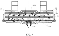
- FIG. 4 shows a silencing path of the silencer shown in FIG. 3 .
- a silencer according to an embodiment of the present invention includes:
- the intake port 800 is formed at an inlet of each first flow guide channel of the first silencing member 10 located at the top layer.
- a gas is first dispersed and guided by the first silencing member 10 at the uppermost layer to reduce the pressure and noise, and the second silencing member 20 at a second layer is configured to gather the guided gas, so that the gas passes through corners of a three-dimensional maze formed by the first silencing member 10 at the uppermost layer and the second silencing member 20 at the second layer to increase air flow resistance and achieve a silencing effect.
- the gas is dispersed and guided by the first silencing member 10 at a third layer to further reduce the pressure and noise, then passes through corners of a three-dimensional maze formed by the first silencing member 10 at the third layer and the second silencing member 20 at a fourth layer to enhance the silencing effect, is gathered and guided by the second silencing member 20 at the fourth layer to a chamber of the exhaust member 30, and is finally discharged through the exhaust hole 33.
- the gas entering the silencer cavity can not only pass through a three-dimensional maze detour path of dispersion, gathering, dispersion and gathering to fully reduce the pressure and noise, but can also be subjected to shock absorption and noise reduction through a flow guide effect, thereby effectively reducing the noise level to a desired range.
- the intake port 800 is formed at an inlet of each second flow guide channel of the second silencing member 20 located at the top layer.
- a gas is first gathered and guided by the second silencing member 20 at the uppermost layer, is then subjected to full pressure and noise reduction under a dispersion flow guide effect of the first silencing member 10 at a second layer, and is then gathered and guided by the second silencing member 20 at a third layer, and the gas passes through a three-dimensional maze detour path in the silencer cavity through dispersion flow guides and gathering flow guides that are alternate vertically, to increase air flow resistance and reduce the pressure and noise to achieve a silencing effect.
- the gas then enters a chamber of the exhaust member 30 after being further subjected to pressure and noise reduction under a dispersion flow guide effect of the first silencing member 10 at a fourth layer, and is finally discharged through the exhaust hole 33.
- the gas entering the silencer cavity can not only pass through the three-dimensional maze detour path of gathering, dispersion, gathering and dispersion to fully reduce the pressure and noise, but can also be subjected to shock absorption and noise reduction through a flow guide effect, thereby effectively reducing the noise level to a desired range.
- FIGS. 1 to 4 only schematically show the structures of two types of silencers according to the embodiments of the present invention.
- the number, stacking order, etc. of first silencing members 10 and second silencing members 20 can be adjusted according to an actual situation, and are not limited to those shown in FIGS. 1 to 4 .
- the first silencing members 10 and the second silencing members 20 are alternately stacked, each first silencing member 10 is provided with dispersed first flow guide channels, and each second silencing member 20 is provided with gathered second flow guide channels, so that the three-dimensional maze silencing path P for alternately dispersing and gathering a gas is formed, which not only effectively reduces the pressure and noise of the gas, but also effectively guides the gas to achieve shock absorption and noise reduction.
- the first flow guide channel includes: a first flow guide surface 11, a downstream of the first flow guide surface 11 being distributed at the edge of the first silencing member 10; an intake cavity 12 provided upstream of the first flow guide surface 11; and notches 13 distributed in a side wall of the intake cavity 12.
- the first flow guide surface 11 may be formed into a curved surface, a cambered surface, an inclined surface, or the like, so as to guide and silence the gas.
- the second flow guide channel includes: a second flow guide surface 21, an upstream of the second flow guide surface 21 being distributed at the edge of the second silencing member 20; and a vent hole 22 provided downstream of the second flow guide surface 21 and aligned with the adjacent intake cavity 12.
- the gas may enter the chamber of the second silencing member 20 from the edge of the second silencing member 20, is guided and silenced along the second flow guide surface 21, and enters the adjacent intake cavity 12 from the vent hole 22.
- the second flow guide surface 21 may be formed into a curved surface, a cambered surface, an inclined surface, or the like, so as to guide and silence the gas.
- each second silencing member 20 is provided with a first flange 25.
- the edge of each first silencing member 10 is in clearance fit with a corresponding first flange 25.
- the edge of the exhaust member 30 is in sealing fit with a corresponding first flange 25, and the first flanges 25 are in sealing fit with each other.
- the edge of the exhaust member 30 is in sealing fit with the first flange 25, and the first flanges 25 are in sealing fit with each other, a sealed housing of the silencer is formed.
- the first flanges 25 may be in tight fit with each other by means of a sealing ring 26. Due to the fact that the edge of each first silencing member 10 is in clearance fit with the first flange 25, a clearance is formed for flow guide.
- each first silencing member 10 is connected to the corresponding first flange 25 via a snap-fit member 18.
- the edge of the exhaust member 30 is connected to the corresponding first flange 25 via a guide pin 40, and the first flanges 25 are connected to each other via the guide pin.
- the first silencing member 10 is firmly fitted with the second silencing member 20.
- the guide pin 40 facilitates positioning and fitting of the exhaust member 30 and the second silencing members 20.
- the first silencing member 10 is made of a porous material, and the first flow guide channel includes pores (not specifically shown in the figures) dispersed in the porous material.
- the second flow guide channel includes pores 28 provided in a central area or a corner area of the second silencing member 20 in a centralized manner.
- the first silencing member 10 may be made of sponge or another suitable porous material, so as to effectively reduce the pressure and noise of the gas.
- the edge of one of the second silencing members 20 is provided with a second flange 29.
- the edge of the first silencing member 10 abuts against the second flange 29, and the edge of the exhaust member 30 is hermetically connected to the second flange 29.
- the silencer further includes: a reinforcing rib 50 arranged at an outer wall of a flange. Radiation noise is reduced by the reinforcing rib 50.
- a convex rib 36 is arranged on a path of the exhaust member 30 leading to the exhaust hole 33.
- air flow resistance can be further increased before the gas is discharged from the silencer, to enhance the silencing effect.
- the silencer further includes: a check valve 60 arranged in the exhaust hole 33 or in a second flow guide channel adjacent to the exhaust hole 33.
- the gas in the silencer is allowed to be discharged, while preventing external moisture from entering the silencer.
- An embodiment of the present invention further provides an electric vacuum pump, which is equipped with a silencer described according to any of the above embodiments.
- An intake port 800 of the silencer is in communication with an exhaust port of the electric vacuum pump.
- the noise level in front of the electric vacuum pump could be reduced from the original 75.3 db to 64.7 db, and the noise level on a side of the electric vacuum pump could be reduced from the original 76.6 db to 69.8 db.
- the overall noise level of the electric vacuum pump can be effectively reduced to 70 db or below, thereby effectively solving the NVH problem of the electric vacuum pump.
- the silencer according to the present invention may be applied to other pneumatic devices, which can also effectively improve the noise level.
- the first silencing members 10 and the second silencing members 20 are alternately stacked, each first silencing member 10 is provided with dispersed first flow guide channels, and each second silencing member 20 is provided with gathered second flow guide channels, so that the three-dimensional maze silencing path P for alternately dispersing and gathering a gas is formed, which not only effectively reduces the pressure and noise of the gas, but also effectively guides the gas to achieve shock absorption and noise reduction.
- the silencer according to the present invention can be provided in pneumatic devices such as an electric vacuum pump, and can effectively reduce the noise level of the pneumatic devices such as the electric vacuum pump.
Landscapes
- Engineering & Computer Science (AREA)
- Mechanical Engineering (AREA)
- General Engineering & Computer Science (AREA)
- Exhaust Silencers (AREA)
Abstract
Description
- The present invention relates to the technical field of silencing, and in particular, to a silencer and an electric vacuum pump.
- In a scenario in which aerodynamic noise needs to be reduced, silencers can be used to reduce the noise level. For example, a silencer is usually provided at an exhaust port of an electric vacuum pump of a vehicle to reduce noise.
- Current silencers usually use some sound-absorbing materials to reduce noise, or are provided with some planar blocking structures to reduce noise, so that the noise reduction level is very limited, which cannot meet noise reduction requirements for devices such as electric vacuum pumps.
- It should be noted that information disclosed in the above background art section is only used to enhance the understanding of the background of the present invention, and therefore may include information that does not constitute the prior art known to those of ordinary skill in the art.
- In view of this, the present invention provides a silencer, which can effectively reduce the noise level by means of a three-dimensional maze silencing path. When the silencer according to the present invention is assembled to an electric vacuum pump, the noise, vibration and harshness (NVH) problem of the electric vacuum pump can be effectively solved.
- An aspect of the present invention provides a silencer, including: first silencing members and second silencing members, which are alternately stacked, each first silencing member being provided with dispersed first flow guide channels, and each second silencing member being provided with gathered second flow guide channels; and an exhaust member provided with an exhaust hole, an edge of the exhaust member being connected to an edge of each silencing member, and the silencer forming a three-dimensional maze silencing path leading to the exhaust hole from an intake port through the alternating first flow guide channels and second flow guide channels.
- In some embodiments, the first flow guide channel includes: a first flow guide surface, a downstream of the first flow guide surface being distributed at the edge of the first silencing member; an intake cavity provided upstream of the first flow guide surface; and notches distributed in a side wall of the intake cavity.
- In some embodiments, the second flow guide channel includes: a second flow guide surface, an upstream of the second flow guide surface being distributed at the edge of the second silencing member; and a vent hole provided downstream of the second flow guide surface and aligned with the adjacent intake cavity.
- In some embodiments, the edge of each second silencing member is provided with a first flange; and the edge of each first silencing member is in clearance fit with a corresponding first flange, the edge of the exhaust member is in sealing fit with a corresponding first flange, and the first flanges are in sealing fit with each other.
- In some embodiments, the edge of each first silencing member is connected to the corresponding first flange via a snap-fit member, the edge of the exhaust member is connected to the corresponding first flange via a guide pin, and the first flanges are connected to each other via the guide pin.
- In some embodiments, the first silencing member is made of a porous material, and the first flow guide channel includes pores dispersed in the porous material; and the second flow guide channel includes pores provided in a central area or a corner area of the second silencing member in a centralized manner.
- In some embodiments, the edge of one of the second silencing members is provided with a second flange; and the edge of the first silencing member abuts against the second flange, and the edge of the exhaust member is hermetically connected to the second flange.
- In some embodiments, the silencer further includes: a reinforcing rib arranged at an outer wall of a flange.
- In some embodiments, a convex rib is arranged on a path of the exhaust member leading to the exhaust hole.
- In some embodiments, the silencer further includes: a check valve arranged in the exhaust hole or in a second flow guide channel adjacent to the exhaust hole.
- Another aspect of the present invention provides an electric vacuum pump, which is equipped with a silencer according to any of the above embodiments, wherein an intake port of the silencer is in communication with an exhaust port of the electric vacuum pump.
- Compared with the prior art, the present invention has at least the following beneficial effects.
- In the silencer according to the present invention, the first silencing members and the second silencing members are alternately stacked, each first silencing member is provided with dispersed first flow guide channels, and each second silencing member is provided with gathered second flow guide channels, so that the three-dimensional maze silencing path for alternately dispersing and gathering a gas is formed, which not only effectively reduces the pressure and noise of the gas, but also effectively guides the gas to achieve shock absorption and noise reduction.
- When the silencer according to the present invention is assembled to an electric vacuum pump, it has been tested that the noise level of the electric vacuum pump can be reduced to 70 db or below, thereby effectively solving the NVH problem of the electric vacuum pump.
- It should be understood that the above general description and the following detailed description are only exemplary and explanatory, and cannot limit the present invention.
- The accompanying drawings herein, which are incorporated into and constitute a part of this description, illustrate embodiments consistent with the present invention and, together with the description, are used to explain principles of the present invention. Obviously, the accompanying drawings described below show merely some of the embodiments of the present invention, and those of ordinary skill in the art would also have obtained other accompanying drawings according to these accompanying drawings without any creative effort.
-
FIG. 1 is a schematic structural diagram of a silencer according to an embodiment of the present invention; -
Fig. 2 is a schematic diagram of a silencing path of the silencer shown inFIG. 1 ; -
FIG. 3 is a schematic structural diagram of another silencer according to an embodiment of the present invention; and -
FIG. 4 is a schematic diagram of a silencing path of the silencer shown inFIG. 3 . - Now exemplary implementations will be described more fully with reference to the accompanying drawings. However, the exemplary implementations can be implemented in many forms and should not be construed as being limited to the implementations set forth herein. On the contrary, these implementations are provided to make the present invention thorough and complete, and to fully convey the concept of the exemplary implementations to those skilled in the art.
- The accompanying drawings are only schematic illustrations of the present invention, and are not necessarily drawn to scale. In the accompanying drawings, the same reference signs denote the same or similar parts, and thus the repeated description thereof will be omitted.
- The terms "first", "second" and similar terms used in the specific description do not denote any order, quantity, or importance, but are merely used to distinguish between different components. Furthermore, In the description of the present invention, orientations or positional relationships indicated by the terms such as "upper" and "lower" are based on orientations or positional relationships shown in the drawings, which is only for convenience of describing the present invention and simplifying the description, rather than indicating or implying that an apparatus or an element referred to must have a specific orientation or be constructed and operated in a specific orientation, and therefore cannot be construed as limiting the present invention.
- It should be noted that the embodiments of the present invention and features of the various embodiments can be combined with each other without conflict.
-
FIG. 1 shows a structure of a silencer according to an embodiment of the present invention.FIG. 2 shows a silencing path of the silencer shown inFIG. 1 .FIG. 3 shows a structure of another silencer according to an embodiment of the present invention.FIG. 4 shows a silencing path of the silencer shown inFIG. 3 . With reference toFIGS. 1 to 4 , a silencer according to an embodiment of the present invention includes: - first
silencing members 10 andsecond silencing members 20, which are alternately stacked, each firstsilencing member 10 being provided with dispersed first flow guide channels (see the arrows marked on thefirst silencing members 10 inFIG. 1 and3 ), and eachsecond silencing member 20 being provided with gathered second flow guide channels (see the arrows marked on thesecond silencing members 20 inFIG. 1 and3 ); and - an
exhaust member 30 provided with anexhaust hole 33. An edge of theexhaust member 30 is connected to an edge of each silencing member, and the silencer forms a three-dimensional maze silencing path P leading to theexhaust hole 33 from anintake port 800 through the alternating first flow guide channels and second flow guide channels. - In the silencer shown in
FIGS. 1 and2 , theintake port 800 is formed at an inlet of each first flow guide channel of thefirst silencing member 10 located at the top layer. When entering a silencer cavity from theintake port 800, a gas is first dispersed and guided by thefirst silencing member 10 at the uppermost layer to reduce the pressure and noise, and thesecond silencing member 20 at a second layer is configured to gather the guided gas, so that the gas passes through corners of a three-dimensional maze formed by thefirst silencing member 10 at the uppermost layer and thesecond silencing member 20 at the second layer to increase air flow resistance and achieve a silencing effect. Then, the gas is dispersed and guided by thefirst silencing member 10 at a third layer to further reduce the pressure and noise, then passes through corners of a three-dimensional maze formed by thefirst silencing member 10 at the third layer and thesecond silencing member 20 at a fourth layer to enhance the silencing effect, is gathered and guided by thesecond silencing member 20 at the fourth layer to a chamber of theexhaust member 30, and is finally discharged through theexhaust hole 33. By the alternating first flow guide channels and second flow guide channels, the gas entering the silencer cavity can not only pass through a three-dimensional maze detour path of dispersion, gathering, dispersion and gathering to fully reduce the pressure and noise, but can also be subjected to shock absorption and noise reduction through a flow guide effect, thereby effectively reducing the noise level to a desired range. - In the silencer shown in
FIGS. 3 and4 , theintake port 800 is formed at an inlet of each second flow guide channel of thesecond silencing member 20 located at the top layer. When entering a silencer cavity from theintake port 800, a gas is first gathered and guided by thesecond silencing member 20 at the uppermost layer, is then subjected to full pressure and noise reduction under a dispersion flow guide effect of thefirst silencing member 10 at a second layer, and is then gathered and guided by thesecond silencing member 20 at a third layer, and the gas passes through a three-dimensional maze detour path in the silencer cavity through dispersion flow guides and gathering flow guides that are alternate vertically, to increase air flow resistance and reduce the pressure and noise to achieve a silencing effect. The gas then enters a chamber of theexhaust member 30 after being further subjected to pressure and noise reduction under a dispersion flow guide effect of thefirst silencing member 10 at a fourth layer, and is finally discharged through theexhaust hole 33. By the alternating second flow guide channels and first flow guide channels, the gas entering the silencer cavity can not only pass through the three-dimensional maze detour path of gathering, dispersion, gathering and dispersion to fully reduce the pressure and noise, but can also be subjected to shock absorption and noise reduction through a flow guide effect, thereby effectively reducing the noise level to a desired range. - It should be noted that
FIGS. 1 to 4 only schematically show the structures of two types of silencers according to the embodiments of the present invention. In other embodiments, the number, stacking order, etc. offirst silencing members 10 andsecond silencing members 20 can be adjusted according to an actual situation, and are not limited to those shown inFIGS. 1 to 4 . - In the silencer according to the present invention, the
first silencing members 10 and thesecond silencing members 20 are alternately stacked, eachfirst silencing member 10 is provided with dispersed first flow guide channels, and eachsecond silencing member 20 is provided with gathered second flow guide channels, so that the three-dimensional maze silencing path P for alternately dispersing and gathering a gas is formed, which not only effectively reduces the pressure and noise of the gas, but also effectively guides the gas to achieve shock absorption and noise reduction. - Referring to
FIGS. 1 and2 , in some embodiments, the first flow guide channel includes: a firstflow guide surface 11, a downstream of the firstflow guide surface 11 being distributed at the edge of thefirst silencing member 10; anintake cavity 12 provided upstream of the firstflow guide surface 11; andnotches 13 distributed in a side wall of theintake cavity 12. - After entering the
intake cavity 12, the gas is dispersed and flows out through thenotches 13, is guided and silenced along the firstflow guide surface 11, and enters a chamber of the adjacentsecond silencing member 20 from the edge of thefirst silencing member 10. The firstflow guide surface 11 may be formed into a curved surface, a cambered surface, an inclined surface, or the like, so as to guide and silence the gas. - With continued reference to
FIGS. 1 and2 , in some embodiments, the second flow guide channel includes: a secondflow guide surface 21, an upstream of the secondflow guide surface 21 being distributed at the edge of thesecond silencing member 20; and avent hole 22 provided downstream of the secondflow guide surface 21 and aligned with theadjacent intake cavity 12. - The gas may enter the chamber of the
second silencing member 20 from the edge of thesecond silencing member 20, is guided and silenced along the secondflow guide surface 21, and enters theadjacent intake cavity 12 from thevent hole 22. The secondflow guide surface 21 may be formed into a curved surface, a cambered surface, an inclined surface, or the like, so as to guide and silence the gas. - With continued reference to
FIGS. 1 and2 , in some embodiments, the edge of each second silencingmember 20 is provided with afirst flange 25. The edge of each first silencingmember 10 is in clearance fit with a correspondingfirst flange 25. The edge of theexhaust member 30 is in sealing fit with a correspondingfirst flange 25, and thefirst flanges 25 are in sealing fit with each other. - Due to the fact that the edge of the
exhaust member 30 is in sealing fit with thefirst flange 25, and thefirst flanges 25 are in sealing fit with each other, a sealed housing of the silencer is formed. Thefirst flanges 25 may be in tight fit with each other by means of a sealingring 26. Due to the fact that the edge of each first silencingmember 10 is in clearance fit with thefirst flange 25, a clearance is formed for flow guide. - With continued reference to
FIGS. 1 and2 , in some embodiments, the edge of each first silencingmember 10 is connected to the correspondingfirst flange 25 via a snap-fit member 18. The edge of theexhaust member 30 is connected to the correspondingfirst flange 25 via aguide pin 40, and thefirst flanges 25 are connected to each other via the guide pin. - By means of the snap-
fit member 18, the first silencingmember 10 is firmly fitted with the second silencingmember 20. Theguide pin 40 facilitates positioning and fitting of theexhaust member 30 and the second silencingmembers 20. - With reference to
FIGS. 3 and4 , in some embodiments, the first silencingmember 10 is made of a porous material, and the first flow guide channel includes pores (not specifically shown in the figures) dispersed in the porous material. The second flow guide channel includespores 28 provided in a central area or a corner area of the second silencingmember 20 in a centralized manner. - The first silencing
member 10 may be made of sponge or another suitable porous material, so as to effectively reduce the pressure and noise of the gas. - With continued reference to
FIGS. 3 and4 , in some embodiments, the edge of one of the second silencingmembers 20 is provided with asecond flange 29. The edge of the first silencingmember 10 abuts against thesecond flange 29, and the edge of theexhaust member 30 is hermetically connected to thesecond flange 29. - Due to the fact that the edge of the
exhaust member 30 is hermetically connected to thesecond flange 29, a sealed housing of the silencer is formed. Due to the fact that the edge of the first silencingmember 10 abuts against thesecond flange 29, full pressure and noise reduction of the gas is implemented through the pores scattered in the first silencingmember 10. - Referring to
FIGS. 1 and3 , in some embodiments, the silencer further includes: a reinforcingrib 50 arranged at an outer wall of a flange. Radiation noise is reduced by the reinforcingrib 50. - With reference to
FIGS. 1 to 4 , in some embodiments, aconvex rib 36 is arranged on a path of theexhaust member 30 leading to theexhaust hole 33. By means of theconvex rib 36, air flow resistance can be further increased before the gas is discharged from the silencer, to enhance the silencing effect. - With continued reference to
FIGS. 1 to 4 , in some embodiments, the silencer further includes: acheck valve 60 arranged in theexhaust hole 33 or in a second flow guide channel adjacent to theexhaust hole 33. - By means of the
check valve 60 arranged at the bottom of the silencer, the gas in the silencer is allowed to be discharged, while preventing external moisture from entering the silencer. - An embodiment of the present invention further provides an electric vacuum pump, which is equipped with a silencer described according to any of the above embodiments. An
intake port 800 of the silencer is in communication with an exhaust port of the electric vacuum pump. - For the electric vacuum pump equipped with the silencer according to the present invention, it has been tested that the noise level in front of the electric vacuum pump could be reduced from the original 75.3 db to 64.7 db, and the noise level on a side of the electric vacuum pump could be reduced from the original 76.6 db to 69.8 db. In this way, the overall noise level of the electric vacuum pump can be effectively reduced to 70 db or below, thereby effectively solving the NVH problem of the electric vacuum pump.
- In addition to being applied to the electric vacuum pump, the silencer according to the present invention may be applied to other pneumatic devices, which can also effectively improve the noise level.
- To sum up, in the silencer according to the present invention, the first silencing
members 10 and the second silencingmembers 20 are alternately stacked, each first silencingmember 10 is provided with dispersed first flow guide channels, and each second silencingmember 20 is provided with gathered second flow guide channels, so that the three-dimensional maze silencing path P for alternately dispersing and gathering a gas is formed, which not only effectively reduces the pressure and noise of the gas, but also effectively guides the gas to achieve shock absorption and noise reduction. - The silencer according to the present invention can be provided in pneumatic devices such as an electric vacuum pump, and can effectively reduce the noise level of the pneumatic devices such as the electric vacuum pump.
- The above is a further detailed description of the present invention with reference to the specific preferred implementations, and it cannot be considered that the specific implementation of the present invention is limited to these descriptions. For those of ordinary skill in the art of the present invention, several simple deductions or substitutions can be further made without departing from the concept of the present invention, and should be regarded as falling within the scope of protection of the present invention.
Claims (11)
- A silencer, characterized by comprising:first silencing members and second silencing members, which are alternately stacked, each first silencing member being provided with dispersed first flow guide channels, and each second silencing member being provided with gathered second flow guide channels; andan exhaust member provided with an exhaust hole, an edge of the exhaust member being connected to an edge of each silencing member, and the silencer forming a three-dimensional maze silencing path leading to the exhaust hole from an intake port through the alternating first flow guide channels and second flow guide channels.
- The silencer according to claim 1, characterized in that the first flow guide channel comprises:a first flow guide surface, a downstream of the first flow guide surface being distributed at the edge of the first silencing member;an intake cavity provided upstream of the first flow guide surface; andnotches distributed in a side wall of the intake cavity.
- The silencer according to claim 2, characterized in that the second flow guide channel comprises:a second flow guide surface, an upstream of the second flow guide surface being distributed at the edge of the second silencing member; anda vent hole provided downstream of the second flow guide surface and aligned with the adjacent intake cavity.
- The silencer according to claim 3, characterized in that the edge of each second silencing member is provided with a first flange; and
the edge of each first silencing member is in clearance fit with a corresponding first flange, the edge of the exhaust member is in sealing fit with a corresponding first flange, and the first flanges are in sealing fit with each other. - The silencer according to claim 4, characterized in that the edge of each first silencing member is connected to the corresponding first flange via a snap-fit member, the edge of the exhaust member is connected to the corresponding first flange via a guide pin, and the first flanges are connected to each other via the guide pin.
- The silencer according to any of the preceding claims, characterized in that the first silencing member is made of a porous material, and the first flow guide channel comprises pores dispersed in the porous material; and
the second flow guide channel comprises pores provided in a central area or a corner area of the second silencing member in a centralized manner. - The silencer according to claim 6, characterized in that the edge of one of the second silencing members is provided with a second flange; and
the edge of the first silencing member abuts against the second flange, and the edge of the exhaust member is hermetically connected to the second flange. - The silencer according to claim 4 or 7, characterized by further comprising:
a reinforcing rib arranged at an outer wall of a flange. - The silencer according to any of the preceding claims, characterized in that a convex rib is arranged on a path of the exhaust member leading to the exhaust hole.
- The silencer according to any of the preceding claims, characterized by further comprising:
a check valve arranged in the exhaust hole or in a second flow guide channel adjacent to the exhaust hole. - An electric vacuum pump, characterized in that it is equipped with a silencer according to any one of claims 1 to 10,
wherein an intake port of the silencer is in communication with an exhaust port of the electric vacuum pump.
Applications Claiming Priority (1)
| Application Number | Priority Date | Filing Date | Title |
|---|---|---|---|
| CN202311351453.4A CN117145728B (en) | 2023-10-18 | 2023-10-18 | Silencer and electric vacuum pump |
Publications (2)
| Publication Number | Publication Date |
|---|---|
| EP4542042A1 true EP4542042A1 (en) | 2025-04-23 |
| EP4542042B1 EP4542042B1 (en) | 2026-01-14 |
Family
ID=88899022
Family Applications (1)
| Application Number | Title | Priority Date | Filing Date |
|---|---|---|---|
| EP24205211.6A Active EP4542042B1 (en) | 2023-10-18 | 2024-10-08 | Silencer and electric vacuum pump |
Country Status (2)
| Country | Link |
|---|---|
| EP (1) | EP4542042B1 (en) |
| CN (1) | CN117145728B (en) |
Citations (3)
| Publication number | Priority date | Publication date | Assignee | Title |
|---|---|---|---|---|
| US20110236932A1 (en) * | 2008-12-19 | 2011-09-29 | Stobbe Tech A/S | Biopharmaceutical plant in a column |
| CN111197899A (en) * | 2020-03-09 | 2020-05-26 | 海信(山东)冰箱有限公司 | a refrigerator |
| WO2021129707A1 (en) * | 2019-12-25 | 2021-07-01 | 曼胡默尔滤清器(上海)有限公司 | Muffler combination apparatus for fuel cell exhaust system |
Family Cites Families (6)
| Publication number | Priority date | Publication date | Assignee | Title |
|---|---|---|---|---|
| CN1648586A (en) * | 2004-12-15 | 2005-08-03 | 庄凤仪 | Water saving, noise reducing powerless back-flow device for central air conditioner cooling tower |
| DE602006001846D1 (en) * | 2006-03-29 | 2008-08-28 | Teuco Guzzini Spa | Silencer device for an air intake duct and whirlpool tub with silencer device |
| CN107701392A (en) * | 2017-09-29 | 2018-02-16 | 臧福运 | A kind of electric vacuum pump |
| CN208519197U (en) * | 2018-07-24 | 2019-02-19 | 浙江力诺流体控制科技股份有限公司 | Variable diameter labyrinth multilevel decompression cage type regulating valve |
| CN218420393U (en) * | 2021-09-24 | 2023-02-03 | 深圳市德达医疗科技集团有限公司 | Silencing device and foot massager |
| CN220909942U (en) * | 2023-10-18 | 2024-05-07 | 采埃孚商用车系统(青岛)有限公司 | Muffler and electric vacuum pump |
-
2023
- 2023-10-18 CN CN202311351453.4A patent/CN117145728B/en active Active
-
2024
- 2024-10-08 EP EP24205211.6A patent/EP4542042B1/en active Active
Patent Citations (3)
| Publication number | Priority date | Publication date | Assignee | Title |
|---|---|---|---|---|
| US20110236932A1 (en) * | 2008-12-19 | 2011-09-29 | Stobbe Tech A/S | Biopharmaceutical plant in a column |
| WO2021129707A1 (en) * | 2019-12-25 | 2021-07-01 | 曼胡默尔滤清器(上海)有限公司 | Muffler combination apparatus for fuel cell exhaust system |
| CN111197899A (en) * | 2020-03-09 | 2020-05-26 | 海信(山东)冰箱有限公司 | a refrigerator |
Also Published As
| Publication number | Publication date |
|---|---|
| CN117145728A (en) | 2023-12-01 |
| EP4542042B1 (en) | 2026-01-14 |
| CN117145728B (en) | 2025-12-26 |
Similar Documents
| Publication | Publication Date | Title |
|---|---|---|
| US10525952B2 (en) | Aspirators for producing vacuum using the venturi effect | |
| CN220909942U (en) | Muffler and electric vacuum pump | |
| CN207093249U (en) | Compound air inlet resonant cavity and automobile | |
| EP4559502A1 (en) | Ventilation assembly and ventilation device | |
| EP4542042B1 (en) | Silencer and electric vacuum pump | |
| JPS6050265A (en) | Device for reducing intake noise of automobile | |
| JP2017508922A (en) | Engine system noise attenuation unit | |
| EP3581798A1 (en) | Noise reducing silencer with a spirally shaped tube for a compressor | |
| US11421690B2 (en) | Silencer and compressor | |
| CN110822504B (en) | Smoke exhaust ventilator | |
| CN209228572U (en) | Noise reduction surge tank | |
| CN215444333U (en) | Big commercial compressor is with amortization chamber of breathing in | |
| EP4144990A1 (en) | Air suction silencer, compressor, and household appliance | |
| CN214860211U (en) | Silencer and ventilator | |
| EP4286762A1 (en) | Muffling device | |
| CN211623830U (en) | Vibration damper for condenser | |
| CN219061811U (en) | Exhaust muffler | |
| US2955671A (en) | Induction silencers for internal combustion engine carburetors | |
| SE523018C2 (en) | Muffler and use of said muffler in an exhaust system for an internal combustion engine | |
| CN220932522U (en) | Prevent feed liquor exhaust tube and gas detector | |
| CN111140508A (en) | Pump and method of operating the same | |
| CN214949750U (en) | Air pipe silencer and central air-conditioning ventilation system | |
| CN115101467B (en) | Silicon wafer bearing device in lithography equipment | |
| CN219413050U (en) | Noise reduction mechanism and waste discharge device | |
| CN224040380U (en) | Silencing air inlet air filter |
Legal Events
| Date | Code | Title | Description |
|---|---|---|---|
| PUAI | Public reference made under article 153(3) epc to a published international application that has entered the european phase |
Free format text: ORIGINAL CODE: 0009012 |
|
| STAA | Information on the status of an ep patent application or granted ep patent |
Free format text: STATUS: THE APPLICATION HAS BEEN PUBLISHED |
|
| AK | Designated contracting states |
Kind code of ref document: A1 Designated state(s): AL AT BE BG CH CY CZ DE DK EE ES FI FR GB GR HR HU IE IS IT LI LT LU LV MC ME MK MT NL NO PL PT RO RS SE SI SK SM TR |
|
| STAA | Information on the status of an ep patent application or granted ep patent |
Free format text: STATUS: REQUEST FOR EXAMINATION WAS MADE |
|
| 17P | Request for examination filed |
Effective date: 20250617 |
|
| GRAP | Despatch of communication of intention to grant a patent |
Free format text: ORIGINAL CODE: EPIDOSNIGR1 |
|
| STAA | Information on the status of an ep patent application or granted ep patent |
Free format text: STATUS: GRANT OF PATENT IS INTENDED |
|
| INTG | Intention to grant announced |
Effective date: 20250911 |
|
| GRAS | Grant fee paid |
Free format text: ORIGINAL CODE: EPIDOSNIGR3 |
|
| GRAA | (expected) grant |
Free format text: ORIGINAL CODE: 0009210 |
|
| STAA | Information on the status of an ep patent application or granted ep patent |
Free format text: STATUS: THE PATENT HAS BEEN GRANTED |
|
| AK | Designated contracting states |
Kind code of ref document: B1 Designated state(s): AL AT BE BG CH CY CZ DE DK EE ES FI FR GB GR HR HU IE IS IT LI LT LU LV MC ME MK MT NL NO PL PT RO RS SE SI SK SM TR |
|
| P01 | Opt-out of the competence of the unified patent court (upc) registered |
Free format text: CASE NUMBER: UPC_APP_0015069_4542042/2025 Effective date: 20251128 |
|
| REG | Reference to a national code |
Ref country code: CH Ref legal event code: F10 Free format text: ST27 STATUS EVENT CODE: U-0-0-F10-F00 (AS PROVIDED BY THE NATIONAL OFFICE) Effective date: 20260114 Ref country code: GB Ref legal event code: FG4D |
|
| REG | Reference to a national code |
Ref country code: DE Ref legal event code: R096 Ref document number: 602024002057 Country of ref document: DE |
|
| REG | Reference to a national code |
Ref country code: IE Ref legal event code: FG4D |
|
| REG | Reference to a national code |
Ref country code: NL Ref legal event code: MP Effective date: 20260114 |
|
| PG25 | Lapsed in a contracting state [announced via postgrant information from national office to epo] |
Ref country code: NL Free format text: LAPSE BECAUSE OF FAILURE TO SUBMIT A TRANSLATION OF THE DESCRIPTION OR TO PAY THE FEE WITHIN THE PRESCRIBED TIME-LIMIT Effective date: 20260114 |
|
| REG | Reference to a national code |
Ref country code: AT Ref legal event code: MK05 Ref document number: 1877275 Country of ref document: AT Kind code of ref document: T Effective date: 20260114 |
|
| PG25 | Lapsed in a contracting state [announced via postgrant information from national office to epo] |
Ref country code: RS Free format text: LAPSE BECAUSE OF FAILURE TO SUBMIT A TRANSLATION OF THE DESCRIPTION OR TO PAY THE FEE WITHIN THE PRESCRIBED TIME-LIMIT Effective date: 20260414 |
|
| PG25 | Lapsed in a contracting state [announced via postgrant information from national office to epo] |
Ref country code: ES Free format text: LAPSE BECAUSE OF FAILURE TO SUBMIT A TRANSLATION OF THE DESCRIPTION OR TO PAY THE FEE WITHIN THE PRESCRIBED TIME-LIMIT Effective date: 20260114 |
|
| PG25 | Lapsed in a contracting state [announced via postgrant information from national office to epo] |
Ref country code: PL Free format text: LAPSE BECAUSE OF FAILURE TO SUBMIT A TRANSLATION OF THE DESCRIPTION OR TO PAY THE FEE WITHIN THE PRESCRIBED TIME-LIMIT Effective date: 20260114 |
|
| PG25 | Lapsed in a contracting state [announced via postgrant information from national office to epo] |
Ref country code: GR Free format text: LAPSE BECAUSE OF FAILURE TO SUBMIT A TRANSLATION OF THE DESCRIPTION OR TO PAY THE FEE WITHIN THE PRESCRIBED TIME-LIMIT Effective date: 20260415 |
|
| REG | Reference to a national code |
Ref country code: LT Ref legal event code: MG9D |
|
| PG25 | Lapsed in a contracting state [announced via postgrant information from national office to epo] |
Ref country code: LT Free format text: LAPSE BECAUSE OF FAILURE TO SUBMIT A TRANSLATION OF THE DESCRIPTION OR TO PAY THE FEE WITHIN THE PRESCRIBED TIME-LIMIT Effective date: 20260114 |
|
| PG25 | Lapsed in a contracting state [announced via postgrant information from national office to epo] |
Ref country code: NO Free format text: LAPSE BECAUSE OF FAILURE TO SUBMIT A TRANSLATION OF THE DESCRIPTION OR TO PAY THE FEE WITHIN THE PRESCRIBED TIME-LIMIT Effective date: 20260414 |
|
| PG25 | Lapsed in a contracting state [announced via postgrant information from national office to epo] |
Ref country code: SE Free format text: LAPSE BECAUSE OF FAILURE TO SUBMIT A TRANSLATION OF THE DESCRIPTION OR TO PAY THE FEE WITHIN THE PRESCRIBED TIME-LIMIT Effective date: 20260114 Ref country code: FI Free format text: LAPSE BECAUSE OF FAILURE TO SUBMIT A TRANSLATION OF THE DESCRIPTION OR TO PAY THE FEE WITHIN THE PRESCRIBED TIME-LIMIT Effective date: 20260114 Ref country code: AT Free format text: LAPSE BECAUSE OF FAILURE TO SUBMIT A TRANSLATION OF THE DESCRIPTION OR TO PAY THE FEE WITHIN THE PRESCRIBED TIME-LIMIT Effective date: 20260114 |
|
| PG25 | Lapsed in a contracting state [announced via postgrant information from national office to epo] |
Ref country code: HR Free format text: LAPSE BECAUSE OF FAILURE TO SUBMIT A TRANSLATION OF THE DESCRIPTION OR TO PAY THE FEE WITHIN THE PRESCRIBED TIME-LIMIT Effective date: 20260114 |
|
| PG25 | Lapsed in a contracting state [announced via postgrant information from national office to epo] |
Ref country code: IS Free format text: LAPSE BECAUSE OF FAILURE TO SUBMIT A TRANSLATION OF THE DESCRIPTION OR TO PAY THE FEE WITHIN THE PRESCRIBED TIME-LIMIT Effective date: 20260514 Ref country code: PT Free format text: LAPSE BECAUSE OF FAILURE TO SUBMIT A TRANSLATION OF THE DESCRIPTION OR TO PAY THE FEE WITHIN THE PRESCRIBED TIME-LIMIT Effective date: 20260514 |
|
| PG25 | Lapsed in a contracting state [announced via postgrant information from national office to epo] |
Ref country code: LV Free format text: LAPSE BECAUSE OF FAILURE TO SUBMIT A TRANSLATION OF THE DESCRIPTION OR TO PAY THE FEE WITHIN THE PRESCRIBED TIME-LIMIT Effective date: 20260114 |
|
| PG25 | Lapsed in a contracting state [announced via postgrant information from national office to epo] |
Ref country code: BG Free format text: LAPSE BECAUSE OF FAILURE TO SUBMIT A TRANSLATION OF THE DESCRIPTION OR TO PAY THE FEE WITHIN THE PRESCRIBED TIME-LIMIT Effective date: 20260114 |