EP4542022A1 - Engine apparatus - Google Patents
Engine apparatus Download PDFInfo
- Publication number
- EP4542022A1 EP4542022A1 EP24205743.8A EP24205743A EP4542022A1 EP 4542022 A1 EP4542022 A1 EP 4542022A1 EP 24205743 A EP24205743 A EP 24205743A EP 4542022 A1 EP4542022 A1 EP 4542022A1
- Authority
- EP
- European Patent Office
- Prior art keywords
- blow
- gas
- returning
- fuel supply
- fuel
- Prior art date
- Legal status (The legal status is an assumption and is not a legal conclusion. Google has not performed a legal analysis and makes no representation as to the accuracy of the status listed.)
- Pending
Links
Images





Classifications
-
- F—MECHANICAL ENGINEERING; LIGHTING; HEATING; WEAPONS; BLASTING
- F02—COMBUSTION ENGINES; HOT-GAS OR COMBUSTION-PRODUCT ENGINE PLANTS
- F02M—SUPPLYING COMBUSTION ENGINES IN GENERAL WITH COMBUSTIBLE MIXTURES OR CONSTITUENTS THEREOF
- F02M21/00—Apparatus for supplying engines with non-liquid fuels, e.g. gaseous fuels stored in liquid form
- F02M21/02—Apparatus for supplying engines with non-liquid fuels, e.g. gaseous fuels stored in liquid form for gaseous fuels
- F02M21/0203—Apparatus for supplying engines with non-liquid fuels, e.g. gaseous fuels stored in liquid form for gaseous fuels characterised by the type of gaseous fuel
- F02M21/0206—Non-hydrocarbon fuels, e.g. hydrogen, ammonia or carbon monoxide
-
- F—MECHANICAL ENGINEERING; LIGHTING; HEATING; WEAPONS; BLASTING
- F02—COMBUSTION ENGINES; HOT-GAS OR COMBUSTION-PRODUCT ENGINE PLANTS
- F02M—SUPPLYING COMBUSTION ENGINES IN GENERAL WITH COMBUSTIBLE MIXTURES OR CONSTITUENTS THEREOF
- F02M37/00—Apparatus or systems for feeding liquid fuel from storage containers to carburettors or fuel-injection apparatus; Arrangements for purifying liquid fuel specially adapted for, or arranged on, internal-combustion engines
- F02M37/0047—Layout or arrangement of systems for feeding fuel
- F02M37/0052—Details on the fuel return circuit; Arrangement of pressure regulators
-
- F—MECHANICAL ENGINEERING; LIGHTING; HEATING; WEAPONS; BLASTING
- F01—MACHINES OR ENGINES IN GENERAL; ENGINE PLANTS IN GENERAL; STEAM ENGINES
- F01M—LUBRICATING OF MACHINES OR ENGINES IN GENERAL; LUBRICATING INTERNAL COMBUSTION ENGINES; CRANKCASE VENTILATING
- F01M13/00—Crankcase ventilating or breathing
-
- F—MECHANICAL ENGINEERING; LIGHTING; HEATING; WEAPONS; BLASTING
- F01—MACHINES OR ENGINES IN GENERAL; ENGINE PLANTS IN GENERAL; STEAM ENGINES
- F01M—LUBRICATING OF MACHINES OR ENGINES IN GENERAL; LUBRICATING INTERNAL COMBUSTION ENGINES; CRANKCASE VENTILATING
- F01M13/00—Crankcase ventilating or breathing
- F01M13/02—Crankcase ventilating or breathing by means of additional source of positive or negative pressure
- F01M13/021—Crankcase ventilating or breathing by means of additional source of positive or negative pressure of negative pressure
-
- F—MECHANICAL ENGINEERING; LIGHTING; HEATING; WEAPONS; BLASTING
- F02—COMBUSTION ENGINES; HOT-GAS OR COMBUSTION-PRODUCT ENGINE PLANTS
- F02D—CONTROLLING COMBUSTION ENGINES
- F02D19/00—Controlling engines characterised by their use of non-liquid fuels, pluralities of fuels, or non-fuel substances added to the combustible mixtures
- F02D19/02—Controlling engines characterised by their use of non-liquid fuels, pluralities of fuels, or non-fuel substances added to the combustible mixtures peculiar to engines working with gaseous fuels
-
- F—MECHANICAL ENGINEERING; LIGHTING; HEATING; WEAPONS; BLASTING
- F02—COMBUSTION ENGINES; HOT-GAS OR COMBUSTION-PRODUCT ENGINE PLANTS
- F02M—SUPPLYING COMBUSTION ENGINES IN GENERAL WITH COMBUSTIBLE MIXTURES OR CONSTITUENTS THEREOF
- F02M25/00—Engine-pertinent apparatus for adding non-fuel substances or small quantities of secondary fuel to combustion-air, main fuel or fuel-air mixture
- F02M25/06—Engine-pertinent apparatus for adding non-fuel substances or small quantities of secondary fuel to combustion-air, main fuel or fuel-air mixture adding lubricant vapours
-
- F—MECHANICAL ENGINEERING; LIGHTING; HEATING; WEAPONS; BLASTING
- F02—COMBUSTION ENGINES; HOT-GAS OR COMBUSTION-PRODUCT ENGINE PLANTS
- F02M—SUPPLYING COMBUSTION ENGINES IN GENERAL WITH COMBUSTIBLE MIXTURES OR CONSTITUENTS THEREOF
- F02M35/00—Combustion-air cleaners, air intakes, intake silencers, or induction systems specially adapted for, or arranged on, internal-combustion engines
- F02M35/10—Air intakes; Induction systems
- F02M35/10209—Fluid connections to the air intake system; their arrangement of pipes, valves or the like
- F02M35/10222—Exhaust gas recirculation [EGR]; Positive crankcase ventilation [PCV]; Additional air admission, lubricant or fuel vapour admission
-
- F—MECHANICAL ENGINEERING; LIGHTING; HEATING; WEAPONS; BLASTING
- F01—MACHINES OR ENGINES IN GENERAL; ENGINE PLANTS IN GENERAL; STEAM ENGINES
- F01M—LUBRICATING OF MACHINES OR ENGINES IN GENERAL; LUBRICATING INTERNAL COMBUSTION ENGINES; CRANKCASE VENTILATING
- F01M13/00—Crankcase ventilating or breathing
- F01M13/02—Crankcase ventilating or breathing by means of additional source of positive or negative pressure
- F01M13/021—Crankcase ventilating or breathing by means of additional source of positive or negative pressure of negative pressure
- F01M2013/027—Crankcase ventilating or breathing by means of additional source of positive or negative pressure of negative pressure with a turbo charger or compressor
-
- F—MECHANICAL ENGINEERING; LIGHTING; HEATING; WEAPONS; BLASTING
- F02—COMBUSTION ENGINES; HOT-GAS OR COMBUSTION-PRODUCT ENGINE PLANTS
- F02M—SUPPLYING COMBUSTION ENGINES IN GENERAL WITH COMBUSTIBLE MIXTURES OR CONSTITUENTS THEREOF
- F02M2700/00—Supplying, feeding or preparing air, fuel, fuel air mixtures or auxiliary fluids for a combustion engine; Use of exhaust gas; Compressors for piston engines
- F02M2700/12—Devices or methods for making a gas mixture for a combustion engine
- F02M2700/123—Fuel supply devices
-
- F—MECHANICAL ENGINEERING; LIGHTING; HEATING; WEAPONS; BLASTING
- F02—COMBUSTION ENGINES; HOT-GAS OR COMBUSTION-PRODUCT ENGINE PLANTS
- F02M—SUPPLYING COMBUSTION ENGINES IN GENERAL WITH COMBUSTIBLE MIXTURES OR CONSTITUENTS THEREOF
- F02M2700/00—Supplying, feeding or preparing air, fuel, fuel air mixtures or auxiliary fluids for a combustion engine; Use of exhaust gas; Compressors for piston engines
- F02M2700/43—Arrangements for supplying air, fuel or auxiliary fluids to a combustion space of mixture compressing engines working with liquid fuel
- F02M2700/4302—Arrangements for supplying air, fuel or auxiliary fluids to a combustion space of mixture compressing engines working with liquid fuel whereby air and fuel are sucked into the mixture conduit
Definitions
- the present invention relates to an engine apparatus that is ran on fuel containing a corrosive substance.
- Patent Document 1 discloses a blow-by gas returning device that includes: an air introducing passage used in an internal combustion engine having an intake passage in which a turbocharger and an intercooler for cooling intake gas pressurized by the turbocharger are provided and through which the intake gas in the intake passage flows into a crankcase of the internal combustion engines; and a gas recirculating passage through which blow-by gas in the crankcase of the internal combustion engine is recirculated into the intake passage.
- the gas recirculating passage communicates with the intake passage on the intake upstream side of the turbocharger, so that the blow-by gas in the crankcase is recirculated to the intake passage and flows into the combustion chamber again.
- the air introducing passage communicates with the intake passage on the intake downstream side of the turbocharger and on the intake upstream side of the intercooler, so that a portion of the air compressed by the turbocharger is supplied into the crankcase to ventilate the inside of the crankcase.
- Patent Document 1 Japanese Patent No. 4383983
- the blow-by gas In the engine apparatus, by supplying the blow-by gas to a combustion chamber together with normal fuel, the blow-by gas is reused as fuel, and an effect of reducing the fuel consumption is expected.
- the fuel component of the blow-by gas blows through from an intake port to an exhaust port at the time of valve overlap of the combustion chamber and flows out to the exhaust side without being burned in the combustion chamber.
- the blow-by gas mixies into the exhaust gas, and causes deterioration of the exhaust gas component and a reduction in the effect of reducing fuel consumption.
- An object of the present invention is to provide an engine apparatus capable of suppressing contamination of intake system components due to return of the blow-by gas to a combustion chamber, suppressing the cost of the intake system components, and prolonging the product life of the intake system components.
- an engine apparatus of the present invention is an engine apparatus that is ran on fuel containing a corrosive substance, and includes a blow-by returning injector or a blow-by returning mixer that returns blow-by gas to a combustion chamber of the engine.
- the present invention provides an engine apparatus capable of suppressing contamination of intake system components due to return of the blow-by gas to a combustion chamber, suppressing the cost of the intake system components, and prolonging the product life of the intake system components.
- the engine apparatus 1 includes an engine 2, an intake passage 3, an exhaust passage 4, a fuel supply path 5, a turbocharger 6, and an intercooler 7.
- the engine apparatus 1 further includes a blow-by path 8, a filter 9, an externally driven pump 10, and a control unit 11.
- the engine apparatus 1 is a gas engine that run introducing fuel (fuel gas) such as gaseous fuel containing toxic and corrosive substances such as ammonia and methanol into a combustion chamber 21a of the engine 2.
- fuel fuel gas
- the fuel is supplied to the combustion chamber 21a as a mixture with air.
- the engine 2 is, for example, a four-stroke engine, and includes a plurality of cylinders 21, and a crankcase 22 in a cylinder block 20. Although six cylinders 21 are illustrated in FIG. 1 , the number of cylinders 21 is not limited to six. As illustrated in FIGS. 1 and 2 , each of the cylinders 21 includes a cylinder portion 23, a piston 24, and a cylinder head 25.
- the cylinder portion 23, for example, is formed to have a cylindrical shape in the cylinder block 20, and the piston 24 is slidably housed in the cylinder portion 23.
- the cylinder head 25 is attached to the upper side of the cylinder portion 23, and defines a combustion chamber 21a on the inner sides of the cylinder portion 23 and the cylinder head 25.
- the cylinder head 25 is provided with an ignition device 26 for igniting the fuel in the combustion chamber 21a.
- the ignition device 26 may comprise a micro pilot type device that injects a small amount of liquid fuel, or may comprise a spark ignition type device that uses an ignition plug. Alternatively, it may have a configuration in which a mixture of a gas fuel and a liquid fuel is compression-ignited.
- the cylinder head 25 has an intake port 29 that communicate with the combustion chamber 21a and an intake valve 30 that open and close the intake port 29.
- the combustion chamber 21a is connected to the intake passage 3 via the intake port 29 or the like, and air or a mixture of air and fuel supplied from the intake passage 3 is introduced into the combustion chamber 21a.
- the cylinder head 25 has an exhaust port 31 communicating with the combustion chamber 21a and an exhaust valve 32 for opening and closing the exhaust port 31.
- the combustion chamber 21a is connected to the exhaust passage 4 via the exhaust port 31 and the like, and exhaust gas generated in the combustion chamber 21a is discharged to the exhaust passage 4.
- an intake manifold 33 having a branched intake flow path 33a branching from the intake passage 3 to each intake port 29 of the plurality of cylinders 21 is provided between the intake passage 3 and the engine 2.
- an exhaust manifold 34 having a branched exhaust passage 34a branching from the exhaust passage 4 to the plurality of cylinders 21 is provided between the exhaust passage 4 and the engine 2.
- the intake manifold 33 is indicated by a broken line
- the exhaust manifold 34 is indicated by a one-dot-chain line.
- the intake passage 3 is connected to the plurality of cylinders 21 of the engine 2 and supplies compressed and cooled air to each of the cylinders 21.
- a mixture of air supplied from the intake passage 3 and fuel supplied from a fuel tank (not illustrated) through the fuel supply path 5 is supplied to the combustion chamber 21a of each of the cylinders 21.
- the turbocharger 6 that compresses the air or the mixture of fuel and air flowing through the intake passage 3 and sends the compressed air or mixture to the downstream side in the intake direction is provided on the upstream side in the intake direction, and the intercooler 7 that cools the air flowing through the intake passage 3 is provided on the downstream side in the intake direction of the turbocharger 6.
- the intake passage 3 may be provided with an air filter (not illustrated) that purifies fresh air and introduces the purified fresh air into the intake passage 3.
- the exhaust passage 4 is connected to the plurality of cylinders 21 of the engine 2, and allows the exhaust gas generated in each cylinder 21 to flow therethrough and be discharged.
- the fuel supply path 5 supplies fuel supplied from a fuel tank (not illustrated) to the engine 2.
- the fuel supply path 5 has a plurality of branched fuel paths 5a branched to feed fuel toward each of the cylinders 21, and the branched fuel paths 5a are connected to the terminal end of the branched intake flow path 33a of the intake manifold 33 provided for each of the cylinders 21.
- the fuel supply path 5 is provided with a main fuel supply device 35 for feeding the fuel fed through the fuel supply path 5 to the combustion chamber 21a of each of the cylinders 21.
- the main fuel supply device 35 includes, for example, a gas admission valve and a gas injector.
- the plurality of main fuel supply devices 35 are provided at the terminal ends of the corresponding branched fuel paths 5a, and inject fuel at the terminal ends of the branched intake flow paths 33a of the intake manifolds 33 for the cylinders 21.
- the main fuel supply devices 35 are controlled by the control unit 11 to inject fuel, and intermittently injects fuel so as to supply fuel to the combustion chamber 21a at a timing at which the exhaust port 31 is closed and the intake port 29 is opened so that the blow-by of the fuel due to the valve overlap of the combustion chamber 21a does not occur.
- the turbocharger 6 compresses the air or air-fuel mixture flowing through the intake passage 3 and sends the compressed air or air-fuel mixture to the downstream side in the intake direction.
- the turbocharger 6 includes a turbine 6a and a compressor 6b.
- the turbine 6a is arranged in the exhaust passage 4, and the compressor 6b is arranged in the intake passage 3.
- the turbine 6a is rotated by exhaust gas flowing through the exhaust passage 4, and the compressor 6b is driven by the rotational force of the turbine 6a, whereby air or air-fuel mixture flowing through the intake passage 3 is compressed.
- the blow-by path 8 is connected from the crankcase 22 to the fuel supply path 5.
- blow-by gas is generated in the crankcase 22.
- the blow-by gas flows through the blow-by path 8.
- the blow-by path 8 is provided with a check valve 36 that prevents fuel from flowing into the blow-by path 8 from the fuel supply path 5.
- blow-by gas flows into the fuel supply path 5 via the blow-by path 8
- the blow-by gas flows together with the fuel in the fuel supply path 5, and the blow-by gas is fed together with the fuel to the combustion chamber 21a of each of the cylinders 21 by the main fuel supply device 35.
- the blow-by gas is circulated through the blow-by path 8 and the fuel supply path 5, and the main fuel supply device 35 functions as a blow-by returning device 37 that returns the blow-by gas to the combustion chamber 21a, for example, a blow-by returning injector 37a.
- the main fuel supply device 35 is controlled by the control unit 11 to intermittently inject fuel, and the main fuel supply device 35 functioning as the blow-by returning injector 37a also intermittently injects the blow-by gas supplied together with the fuel so as to return the blow-by gas to the combustion chamber 21a at the timing when the exhaust port 31 is closed and the intake port 29 is opened so that the blow-by of the fuel due to the valve overlap of the combustion chamber 21a does not occur.
- the filter 9 is provided on the upstream side in the flow direction of the blow-by gas in the blow-by path 8.
- the filter 9 separates oil mist contained in the blow-by gas flowing through the blow-by path 8 to form an unburned air-fuel mixture, and is formed of, for example, a mist separator.
- the externally driven pump 10 is provided downstream of the filter 9 in the blow-by gas flow direction in the blow-by path 8.
- the externally driven pump 10 is driven while the engine 2 rans (operates) (while fuel is supplied through the fuel supply path 5) to cause the blow-by gas to flow through the blow-by path 8 communicating with the crankcase 22, thereby sucking and/or pressurizing the blow-by gas to be merged the blow-by gas into the fuel supply path 5.
- the externally driven pump 10 causes the blow-by gas to flow in the blow-by path 8, thereby ventilating the inside of the crankcase 22 and setting the inside of the crankcase 22 to a negative pressure.
- the blow-by gas in the crankcase 22 is prevented from leaking from the crankcase 22 at a location other than the blow-by path 8, and for example, the blow-by gas is prevented from leaking from the crankcase 22 at a location where the crankshaft 27 is supported.
- the externally driven pump 10 may be driven with the same strength to cause the blow-by gas to flow with the same strength regardless of whether or not the engine 2 is running (operating). Alternatively, the externally driven pump 10 may be driven at a relatively high intensity when the engine 2 is operating, and may be driven at a relatively low intensity when the engine 2 is stopped. Alternatively, the externally driven pump 10 may be driven until a predetermined time passes after the engine 2 is stopped, and the driving of the external drive pump 10 may be stopped after the predetermined time.
- the control unit 11 is a computer such as an engine control unit (ECU) that controls operation of the engine 2, is provided with a CPU, a ROM, a RAM, and the like, and is configured to control each unit of the engine 2.
- the control unit 11 may store various programs for controlling the engine 2 and control the engine 2 by reading out a program and executing same.
- control unit 11 controls the injection timing of fuel by the main fuel supply device 35 and the injection timing of the blow-by gas by the blow-by returning injector 37a so that the blow-by of fuel due to the valve overlap of the combustion chamber 21a does not occur.
- the engine apparatus 1 runs on fuel containing a corrosive substance, and includes the blow-by returning injector 37a that returns the blow-by gas generated in the crankcase 22 of the engine 2 to the combustion chamber 21a of the engine 2.
- the corrosive substance contained in the fuel is ammonia or methanol.
- the engine apparatus 1 is provided with the blow-by returning injector 37a for returning the blow-by gas containing a corrosive substance, so that the returning position of the blow-by gas can be set so as to suppress the flow of the blow-by gas in the intake system components such as the intake passage 3, the turbocharger 6, and the intercooler. Therefore, contamination of the intake system components by the blow-by gas can be suppressed to a minimum, to prolong the replacement interval of the intake system components. Since the intake system components can be formed by omitting a corrosion-resistant member or a corrosion-resistant coating for the blow-by gas, it is possible to suppress an increase in the cost of the intake system components and to suppress a decrease in the commercial value of the intake system components.
- the engine apparatus 1 includes the fuel supply path 5 for supplying fuel to the engine 2 and the blow-by path 8 connected from the crankcase 22 to the fuel supply path 5, and causes the blow-by gas to flow to the blow-by returning injector 37a via the blow-by path 8 and the fuel supply path 5.
- the engine apparatus 1 includes the main fuel supply device 35 that supplies fuel supplied via the fuel supply path 5 to the combustion chamber 21a.
- the main fuel supply device 35 functions as a blow-by returning injector 37a that returns the blow-by gas supplied together with fuel via the fuel supply path 5 to the combustion chamber 21a.
- the engine apparatus 1 returns the blow-by gas not to the intake passage 3 but to the fuel supply path 5, thereby making it possible to suppress contamination of the intake passage 3 by the blow-by gas. Since the fuel supply path 5 is originally based on the premise that fuel containing corrosive substance is circulated, it is not necessary to take a new contamination countermeasure against the returning of the blow-by gas containing corrosive substance.
- the engine apparatus 1 includes the externally driven pump 10 that causes the blow-by gas to flow in the blow-by path 8, and the blow-by gas is sucked and/or pressurized by the externally driven pump 10 to be merged into the fuel supply path 5.
- the engine apparatus 1 can ventilate the inside of the crankcase 22 and make the inside of the crankcase 22 negative pressure by the externally driven pump 10. Therefore, the blow-by gas in the crankcase 22 can be prevented from leaking from the crankcase 22 at a location other than the blow-by path 8.
- the engine apparatus 1 of the above-described embodiment describes an example in which the fuel supply path 5 includes the plurality of branched fuel paths 5a to supply fuel to each of the cylinders 21, and the plurality of main fuel supply devices 35 includes the gas admission valve, the gas injector, and the like are provided in each of the branched fuel paths 5a.
- the present invention is not limited to this example.
- the fuel supply path 5 may be formed without branching into a plurality of the branched fuel paths 5a, and the single main fuel supply device 35 formed by a gas mixing device such as a venturi mixer or a single point injector may be provided at the end of the fuel supply path 5 and connected to the intake manifold 33 before branching into the branched intake flow paths 33a or the intake passage 3 immediately before the intake manifold 33.
- the main fuel supply device 35 mixes fuel with air flowing through the intake passage 3 and the intake manifold 33.
- the main fuel supply device 35 functions as a blow-by returning device 37 that returns the blow-by gas to the combustion chamber 21a, for example, a blow-by returning mixer 37b, and mixes the blow-by gas together with fuel with the air circulated in the intake passage 3 and the intake manifold 33.
- the engine apparatus 1 of the above-described embodiment describes an example in which the blow-by path 8 is connected to the fuel supply path 5 to merged the blow-by gas with the fuel, and the main fuel supply device 35 that supplies the fuel supplied via the fuel supply path 5 to the combustion chamber 21a of each of the cylinders 21 functions as the blow-by returning device 37, such as the blow-by returning injector 21a or the blow-by returning mixer 37b, that returns the blow-by gas to the combustion chamber 37b.
- the present invention is not limited to this example.
- the engine apparatus 1 may be formed such that the blow-by path 8 is not connected to the fuel supply path 5 and the blow-by gas is merged with the air-fuel mixture, and the blow-by returning device 37, such as the blow-by returning injector 37a, independent of the main fuel supply device 35 may be provided at the terminal end of the blow-by path 8. That is, the blow-by path 8 allows the blow-by gas to directly flow to the blow-by returning injector 37a.
- blow-by path 8 branches into a plurality of branched blow-by paths 8a corresponding to the cylinders 21, and the blow-by returning injectors 37a independent of the main fuel supply device 35 are provided at respective terminal ends of the branched blow-by paths 8a.
- the blow-by returning injector 37a intermittently injects the blow-by gas so as to return the blow-by gas to the combustion chamber 21a at the timing when the exhaust port 31 is closed and the intake port 29 is opened so that the blow-by of the fuel due to the valve overlap of the combustion chamber 21a does not occur.
- the branched blow-by paths 8a of the blow-by path 8 are connected to the branched intake flow paths 33a of the intake manifolds 33 of each of the cylinders 21, and the branched blow-by paths 8a provided in the blow-by returning injectors 37a return the blow-by gas to the respective combustion chambers 21a by injecting the blow-by gas at the terminal ends of the branched intake flow paths 33a of the intake manifolds 33 of each of the cylinders 21.
- the blow-by returning injectors 37a may be provided in the branched intake flow paths 33a on the downstream side of the main fuel supply device 35 in the intake direction.
- the branched blow-by paths 8a of the blow-by path 8 are connected to the cylinder heads 25 of the cylinders 21, and the blow-by returning injectors 37a provided in the branched blow-by paths 8a return the blow-by gas to the corresponding combustion chambers 21a by injecting the blow-by gas by the cylinder heads 25 of the cylinders 21.
- each blow-by returning injector 37a is provided in the corresponding cylinder head 25 in a state of communicating with the combustion chamber 21a so as to directly inject blow-by gas to the combustion chamber 21a.
- the main fuel supply device 35 such as a gas admission valve or a gas injector, may alternatively be provided in the cylinder head 25 in a state of communicating with the combustion chamber 21a so as to directly inject fuel into the combustion chamber 21a.
- the blow-by returning injector 37a is provided in the cylinder head 25 in a state of communicating with the intake port 29 so as to inject the blow-by gas into the intake port 29 communicating with the combustion chamber 21a.
- the main fuel supply device 35 such as a gas admission valve or a gas injector, may alternatively be provided in the cylinder head 25 in a state of communicating with the intake port 29 so as to inject fuel into the intake port 29.
- the blow-by path 8 is connected to the intake manifold 33 before branching to the branched intake flow paths 33a or to the intake passage 3 immediately before the intake manifold 33, and the single blow-by returning device 37 including a gas mixing device, such as a venturi mixer or a single point injector, independent of the main fuel supply device 35, for example, a blow-by returning mixer 37b, may be provided at the terminal end of the blow-by path 8. That is, the blow-by path 8 allows the blow-by gas to directly flow to the blow-by returning mixer 37b.
- a gas mixing device such as a venturi mixer or a single point injector
- the main fuel supply device 35 includes a gas mixing device, such as a venturi mixer or a single point injector, and the blow-by returning mixer 37b is preferably provided on the downstream side of the main fuel supply device 35 in the intake direction.
- the blow-by returning mixer 37b mixes the blow-by gas with the air flowing through the intake passage 3 and the intake manifold 33.
- the externally driven pump 10 causes the blow-by gas to flow in the blow-by path 8 communicating with the crankcase 22 to suck and/or pressurize the blow-by gas, thereby supplying the blow-by gas to the blow-by returning device 37, such as the blow-by returning injector 37a or the blow-by returning mixer 37b, via the blow-by path 8.
- the engine apparatus 1 includes the blow-by path 8 that is connected from the crankcase 22 to the blow-by returning device 37, such as the blow-by returning injector 37a or the blow-by returning mixer 37b, and causes the blow-by gas to flow to the blow-by returning device 37, such as the blow-by returning injector 37a or the blow-by returning mixer 37b.
- the engine apparatus 1 since the engine apparatus 1 includes the dedicated blow-by path 8 through which the blow-by gas flows, in this way, it is possible to suppress the flow of the blow-by gas in the intake system components, such as the intake passage 3, the turbocharger 6, and the intercooler. Therefore, it is possible to minimize the contamination of the intake system components by the blow-by gas, and to prolong the replacement interval of the intake system components.
- the engine apparatus 1 includes the fuel supply path 5 that supplies fuel to the engine 2, the main fuel supply device 35 that supplies fuel supplied via the fuel supply path 5 to the combustion chambers 21a, and the externally driven pump 10 that causes the blow-by gas to flow in the blow-by path 8.
- the blow-by returning device 37 such as the blow-by returning injector 37a or the blow-by returning mixer 37b, is provided independently of the main fuel supply device 35, and the blow-by gas is sucked and/or pressurized by the externally driven pump 10 and is supplied to the blow-by returning device 37, such as the blow-by returning injector 37a or the blow-by returning mixer 37b.
- the blow-by returning injector 37a returns the blow-by gas to the combustion chamber 21a by directly injecting the blow-by gas to the combustion chamber 21a, injecting the blow-by gas to the intake port 29 communicating with the combustion chamber 21a, or injecting the blow-by gas to the terminal end of the intake manifold 33 connected to the combustion chamber 21a.
- the engine apparatus 1 since the engine apparatus 1 includes the dedicated blow-by path 8 through which the blow-by gas flows, it is possible to suppress the flow of the blow-by gas not only in the intake system components but also in the fuel supply path 5 and the main fuel supply device 35. Therefore, contamination of the fuel supply path 5 and the main fuel supply device 35 by the blow-by gas can be suppressed to a minimum, to prolong the replacement interval of the fuel supply path 5 and the main fuel supply device 35.
- the blow-by returning injector 37a intermittently injects the blow-by gas.
- the engine apparatus 1 it is possible to suppress the fuel components of the blow-by gas from blowing through from the intake port 29 to the exhaust port 31 and flowing out to the exhaust side without being combusted at the time of valve overlap of the combustion chamber 21a. Therefore, the mixing of the blow-by gas with the exhaust gas can be suppressed, the deterioration of exhaust gas properties caused by the blow-by gas can be suppressed, and the effect of returning fuel consumption can be improved.
- An engine apparatus that is ran on fuel including a corrosive substance, the apparatus comprising: a blow-by returning injector or a blow-by returning mixer that returns blow-by gas to a combustion chamber of the engine.
- the engine apparatus further comprising an external drive pump that allows the blow-by gas to flow in the blow-by path, wherein the blow-by gas is sucked, pressurized, or both sucked and pressurized by the external drive pump to merge the blow-by gas into the fuel supply path.
- the engine apparatus according to Supplementary Note 1, further comprising: a blow-by path that is connected to the blow-by returning injector or the blow-by returning mixer and allows the blow-by gas to flow to the blow-by returning injector or the blow-by returning mixer.
- blow-by returning injector injects the blow-by gas directly into the combustion chamber, injects the blow-by gas into an intake port communicating with the combustion chamber, or injects the blow-by gas into a terminal end of an intake manifold connected to the combustion chamber.
Landscapes
- Engineering & Computer Science (AREA)
- Mechanical Engineering (AREA)
- General Engineering & Computer Science (AREA)
- Chemical & Material Sciences (AREA)
- Combustion & Propulsion (AREA)
- Chemical Kinetics & Catalysis (AREA)
- General Chemical & Material Sciences (AREA)
- Oil, Petroleum & Natural Gas (AREA)
- Lubrication Details And Ventilation Of Internal Combustion Engines (AREA)
- Output Control And Ontrol Of Special Type Engine (AREA)
Abstract
[Problem] Provided is an engine apparatus that is capable of suppressing contamination of intake system components due to return of blow-by gas to a combustion chamber, suppressing the cost of the intake system components, and prolonging the product life of the intake system components.
[Solution] The engine apparatus runs on fuel containing a corrosive substance and includes a blow-by returning injector that returns the blow-by gas to the combustion chamber of the engine. The corrosive substance contained in the fuel is ammonia or methanol.
Description
- The present invention relates to an engine apparatus that is ran on fuel containing a corrosive substance.
- Conventionally, some engine apparatuses run on fuels containing corrosive substances such as ammonia and methanol. In the engine apparatus, the fuel gas supplied to a combustion chamber may leak into a crank chamber (crankcase) as blow-by gas. Therefore, it is required to treat such blow-by gas in the engine apparatus.
- For example,
Patent Document 1 discloses a blow-by gas returning device that includes: an air introducing passage used in an internal combustion engine having an intake passage in which a turbocharger and an intercooler for cooling intake gas pressurized by the turbocharger are provided and through which the intake gas in the intake passage flows into a crankcase of the internal combustion engines; and a gas recirculating passage through which blow-by gas in the crankcase of the internal combustion engine is recirculated into the intake passage. The gas recirculating passage communicates with the intake passage on the intake upstream side of the turbocharger, so that the blow-by gas in the crankcase is recirculated to the intake passage and flows into the combustion chamber again. The air introducing passage communicates with the intake passage on the intake downstream side of the turbocharger and on the intake upstream side of the intercooler, so that a portion of the air compressed by the turbocharger is supplied into the crankcase to ventilate the inside of the crankcase. - Patent Document 1:
Japanese Patent No. 4383983 - In the case of an engine apparatus that runs on fuel containing a corrosive substance, as in the conventional technique such as
Patent Document 1, since the toxic and corrosive fuel containing, for example, ammonia, flows into the upstream side of the intake passage in the intake direction, not only the intake passage but also the intake system components such as the turbocharger and the intercooler are contaminated (corroded), and there is a concern that the replacement interval (product life) of the intake system components is shortened. To avoid such risk, it is necessary to use a corrosion-resistant material for the intake system components or to apply a corrosion-resistant coating to the intake system components. However, in this case, there is a concern that the cost will increase and the marketability will decrease. - In the engine apparatus, by supplying the blow-by gas to a combustion chamber together with normal fuel, the blow-by gas is reused as fuel, and an effect of reducing the fuel consumption is expected. However, in the conventional technique, there is a risk that the fuel component of the blow-by gas blows through from an intake port to an exhaust port at the time of valve overlap of the combustion chamber and flows out to the exhaust side without being burned in the combustion chamber. In such a case, the blow-by gas mixies into the exhaust gas, and causes deterioration of the exhaust gas component and a reduction in the effect of reducing fuel consumption.
- An object of the present invention is to provide an engine apparatus capable of suppressing contamination of intake system components due to return of the blow-by gas to a combustion chamber, suppressing the cost of the intake system components, and prolonging the product life of the intake system components.
- In order to solve the above problem, an engine apparatus of the present invention is an engine apparatus that is ran on fuel containing a corrosive substance, and includes a blow-by returning injector or a blow-by returning mixer that returns blow-by gas to a combustion chamber of the engine.
- The present invention provides an engine apparatus capable of suppressing contamination of intake system components due to return of the blow-by gas to a combustion chamber, suppressing the cost of the intake system components, and prolonging the product life of the intake system components.
-
-
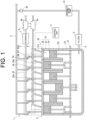
FIG. 1 is a schematic diagram illustrating an example of an engine apparatus according to an embodiment of the present invention. -
FIG. 2 is a schematic diagram illustrating an example of an engine cylinder of an engine apparatus according to an embodiment of the present invention. -
FIG. 3 is a schematic diagram illustrating an example of an engine apparatus according to a first modification of the present invention. -
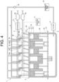
FIG. 4 is a schematic diagram illustrating an example of an engine apparatus according to a second modification of the present invention. -
FIG. 5 is a schematic diagram illustrating an example of an engine apparatus according to a third modification of the present invention. -
FIG. 6 is a schematic diagram illustrating an example of an engine cylinder of an engine apparatus according to the third modification of the present invention. -
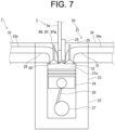
FIG. 7 is a schematic diagram illustrating an example of an engine cylinder of an engine apparatus according to the third modification of the present invention. -
FIG. 8 is a schematic diagram illustrating an example of an engine apparatus according to a fourth modification of the present invention. - An
engine apparatus 1 according to an embodiment of the present invention will be described with reference to drawings. As illustrated inFIG. 1 , theengine apparatus 1 includes anengine 2, anintake passage 3, anexhaust passage 4, afuel supply path 5, a turbocharger 6, and anintercooler 7. Theengine apparatus 1 further includes a blow-bypath 8, afilter 9, an externally drivenpump 10, and acontrol unit 11. - In the present embodiment, in particular, the
engine apparatus 1 is a gas engine that run introducing fuel (fuel gas) such as gaseous fuel containing toxic and corrosive substances such as ammonia and methanol into acombustion chamber 21a of theengine 2. The fuel is supplied to thecombustion chamber 21a as a mixture with air. - The
engine 2 is, for example, a four-stroke engine, and includes a plurality ofcylinders 21, and acrankcase 22 in acylinder block 20. Although sixcylinders 21 are illustrated inFIG. 1 , the number ofcylinders 21 is not limited to six. As illustrated inFIGS. 1 and2 , each of thecylinders 21 includes acylinder portion 23, apiston 24, and acylinder head 25. - The
cylinder portion 23, for example, is formed to have a cylindrical shape in thecylinder block 20, and thepiston 24 is slidably housed in thecylinder portion 23. Thecylinder head 25 is attached to the upper side of thecylinder portion 23, and defines acombustion chamber 21a on the inner sides of thecylinder portion 23 and thecylinder head 25. Thecylinder head 25 is provided with anignition device 26 for igniting the fuel in thecombustion chamber 21a. Theignition device 26 may comprise a micro pilot type device that injects a small amount of liquid fuel, or may comprise a spark ignition type device that uses an ignition plug. Alternatively, it may have a configuration in which a mixture of a gas fuel and a liquid fuel is compression-ignited. - Each
cylinder portion 23 of each of thecylinders 21 communicates with thecrankcase 22, and acrankshaft 27 is rotatably supported by thecrankcase 22. Thepiston 24 of eachcylinder 21 is connected to thecrankshaft 27 via a connectingrod 28, and a reciprocating motion of thepiston 24 is converted into a rotational motion of thecrankshaft 27 via the connectingrod 28. - The
cylinder head 25 has anintake port 29 that communicate with thecombustion chamber 21a and anintake valve 30 that open and close theintake port 29. Thecombustion chamber 21a is connected to theintake passage 3 via theintake port 29 or the like, and air or a mixture of air and fuel supplied from theintake passage 3 is introduced into thecombustion chamber 21a. Thecylinder head 25 has anexhaust port 31 communicating with thecombustion chamber 21a and anexhaust valve 32 for opening and closing theexhaust port 31. Thecombustion chamber 21a is connected to theexhaust passage 4 via theexhaust port 31 and the like, and exhaust gas generated in thecombustion chamber 21a is discharged to theexhaust passage 4. - In order to connect the
intake passage 3 and the plurality ofcylinders 21, anintake manifold 33 having a branchedintake flow path 33a branching from theintake passage 3 to eachintake port 29 of the plurality ofcylinders 21 is provided between theintake passage 3 and theengine 2. In order to connect theexhaust passage 4 and the plurality ofcylinders 21, anexhaust manifold 34 having abranched exhaust passage 34a branching from theexhaust passage 4 to the plurality ofcylinders 21 is provided between theexhaust passage 4 and theengine 2. InFIG. 1 , theintake manifold 33 is indicated by a broken line, and theexhaust manifold 34 is indicated by a one-dot-chain line. - The
intake passage 3 is connected to the plurality ofcylinders 21 of theengine 2 and supplies compressed and cooled air to each of thecylinders 21. A mixture of air supplied from theintake passage 3 and fuel supplied from a fuel tank (not illustrated) through thefuel supply path 5 is supplied to thecombustion chamber 21a of each of thecylinders 21. In theintake passage 3, the turbocharger 6 that compresses the air or the mixture of fuel and air flowing through theintake passage 3 and sends the compressed air or mixture to the downstream side in the intake direction is provided on the upstream side in the intake direction, and theintercooler 7 that cools the air flowing through theintake passage 3 is provided on the downstream side in the intake direction of the turbocharger 6. Theintake passage 3 may be provided with an air filter (not illustrated) that purifies fresh air and introduces the purified fresh air into theintake passage 3. - The
exhaust passage 4 is connected to the plurality ofcylinders 21 of theengine 2, and allows the exhaust gas generated in eachcylinder 21 to flow therethrough and be discharged. - The
fuel supply path 5 supplies fuel supplied from a fuel tank (not illustrated) to theengine 2. For example, thefuel supply path 5 has a plurality ofbranched fuel paths 5a branched to feed fuel toward each of thecylinders 21, and thebranched fuel paths 5a are connected to the terminal end of the branchedintake flow path 33a of theintake manifold 33 provided for each of thecylinders 21. - The
fuel supply path 5 is provided with a mainfuel supply device 35 for feeding the fuel fed through thefuel supply path 5 to thecombustion chamber 21a of each of thecylinders 21. The mainfuel supply device 35 includes, for example, a gas admission valve and a gas injector. For example, in order to supply fuel to each of the plurality ofcylinders 21, the plurality of mainfuel supply devices 35 are provided at the terminal ends of the correspondingbranched fuel paths 5a, and inject fuel at the terminal ends of the branchedintake flow paths 33a of theintake manifolds 33 for thecylinders 21. - When fuel is supplied to each of the
cylinders 21, the mainfuel supply devices 35 are controlled by thecontrol unit 11 to inject fuel, and intermittently injects fuel so as to supply fuel to thecombustion chamber 21a at a timing at which theexhaust port 31 is closed and theintake port 29 is opened so that the blow-by of the fuel due to the valve overlap of thecombustion chamber 21a does not occur. - The turbocharger 6 compresses the air or air-fuel mixture flowing through the
intake passage 3 and sends the compressed air or air-fuel mixture to the downstream side in the intake direction. The turbocharger 6 includes aturbine 6a and acompressor 6b. Theturbine 6a is arranged in theexhaust passage 4, and thecompressor 6b is arranged in theintake passage 3. Theturbine 6a is rotated by exhaust gas flowing through theexhaust passage 4, and thecompressor 6b is driven by the rotational force of theturbine 6a, whereby air or air-fuel mixture flowing through theintake passage 3 is compressed. - The blow-by
path 8 is connected from thecrankcase 22 to thefuel supply path 5. When fuel gas leaks from thecombustion chamber 21a of each of thecylinders 21 to thecrankcase 22, blow-by gas is generated in thecrankcase 22. However, the blow-by gas flows through the blow-bypath 8. The blow-bypath 8 is provided with acheck valve 36 that prevents fuel from flowing into the blow-bypath 8 from thefuel supply path 5. - When the blow-by gas flows into the
fuel supply path 5 via the blow-bypath 8, the blow-by gas flows together with the fuel in thefuel supply path 5, and the blow-by gas is fed together with the fuel to thecombustion chamber 21a of each of thecylinders 21 by the mainfuel supply device 35. In this way, the blow-by gas is circulated through the blow-bypath 8 and thefuel supply path 5, and the mainfuel supply device 35 functions as a blow-by returning device 37 that returns the blow-by gas to thecombustion chamber 21a, for example, a blow-by returning injector 37a. - As described above, the main
fuel supply device 35 is controlled by thecontrol unit 11 to intermittently inject fuel, and the mainfuel supply device 35 functioning as the blow-by returning injector 37a also intermittently injects the blow-by gas supplied together with the fuel so as to return the blow-by gas to thecombustion chamber 21a at the timing when theexhaust port 31 is closed and theintake port 29 is opened so that the blow-by of the fuel due to the valve overlap of thecombustion chamber 21a does not occur. - The
filter 9 is provided on the upstream side in the flow direction of the blow-by gas in the blow-bypath 8. Thefilter 9 separates oil mist contained in the blow-by gas flowing through the blow-bypath 8 to form an unburned air-fuel mixture, and is formed of, for example, a mist separator. - The externally driven
pump 10 is provided downstream of thefilter 9 in the blow-by gas flow direction in the blow-bypath 8. The externally drivenpump 10 is driven while theengine 2 rans (operates) (while fuel is supplied through the fuel supply path 5) to cause the blow-by gas to flow through the blow-bypath 8 communicating with thecrankcase 22, thereby sucking and/or pressurizing the blow-by gas to be merged the blow-by gas into thefuel supply path 5. The externally drivenpump 10 causes the blow-by gas to flow in the blow-bypath 8, thereby ventilating the inside of thecrankcase 22 and setting the inside of thecrankcase 22 to a negative pressure. Accordingly, the blow-by gas in thecrankcase 22 is prevented from leaking from thecrankcase 22 at a location other than the blow-bypath 8, and for example, the blow-by gas is prevented from leaking from thecrankcase 22 at a location where thecrankshaft 27 is supported. - The externally driven
pump 10 may be driven with the same strength to cause the blow-by gas to flow with the same strength regardless of whether or not theengine 2 is running (operating). Alternatively, the externally drivenpump 10 may be driven at a relatively high intensity when theengine 2 is operating, and may be driven at a relatively low intensity when theengine 2 is stopped. Alternatively, the externally drivenpump 10 may be driven until a predetermined time passes after theengine 2 is stopped, and the driving of theexternal drive pump 10 may be stopped after the predetermined time. - The
control unit 11 is a computer such as an engine control unit (ECU) that controls operation of theengine 2, is provided with a CPU, a ROM, a RAM, and the like, and is configured to control each unit of theengine 2. Thecontrol unit 11 may store various programs for controlling theengine 2 and control theengine 2 by reading out a program and executing same. - In particular, the
control unit 11 controls the injection timing of fuel by the mainfuel supply device 35 and the injection timing of the blow-by gas by the blow-by returning injector 37a so that the blow-by of fuel due to the valve overlap of thecombustion chamber 21a does not occur. - As described above, according to the present embodiment, the
engine apparatus 1 runs on fuel containing a corrosive substance, and includes the blow-by returning injector 37a that returns the blow-by gas generated in thecrankcase 22 of theengine 2 to thecombustion chamber 21a of theengine 2. The corrosive substance contained in the fuel is ammonia or methanol. - Accordingly, the
engine apparatus 1 is provided with the blow-by returning injector 37a for returning the blow-by gas containing a corrosive substance, so that the returning position of the blow-by gas can be set so as to suppress the flow of the blow-by gas in the intake system components such as theintake passage 3, the turbocharger 6, and the intercooler. Therefore, contamination of the intake system components by the blow-by gas can be suppressed to a minimum, to prolong the replacement interval of the intake system components. Since the intake system components can be formed by omitting a corrosion-resistant member or a corrosion-resistant coating for the blow-by gas, it is possible to suppress an increase in the cost of the intake system components and to suppress a decrease in the commercial value of the intake system components. - According to the present embodiment, the
engine apparatus 1 includes thefuel supply path 5 for supplying fuel to theengine 2 and the blow-bypath 8 connected from thecrankcase 22 to thefuel supply path 5, and causes the blow-by gas to flow to the blow-by returning injector 37a via the blow-bypath 8 and thefuel supply path 5. - Specifically, according to the present embodiment, the
engine apparatus 1 includes the mainfuel supply device 35 that supplies fuel supplied via thefuel supply path 5 to thecombustion chamber 21a. The mainfuel supply device 35 functions as a blow-by returning injector 37a that returns the blow-by gas supplied together with fuel via thefuel supply path 5 to thecombustion chamber 21a. - Accordingly, the
engine apparatus 1 returns the blow-by gas not to theintake passage 3 but to thefuel supply path 5, thereby making it possible to suppress contamination of theintake passage 3 by the blow-by gas. Since thefuel supply path 5 is originally based on the premise that fuel containing corrosive substance is circulated, it is not necessary to take a new contamination countermeasure against the returning of the blow-by gas containing corrosive substance. - According to the present embodiment, the
engine apparatus 1 includes the externally drivenpump 10 that causes the blow-by gas to flow in the blow-bypath 8, and the blow-by gas is sucked and/or pressurized by the externally drivenpump 10 to be merged into thefuel supply path 5. - Accordingly, the
engine apparatus 1 can ventilate the inside of thecrankcase 22 and make the inside of thecrankcase 22 negative pressure by the externally drivenpump 10. Therefore, the blow-by gas in thecrankcase 22 can be prevented from leaking from thecrankcase 22 at a location other than the blow-bypath 8. - The
engine apparatus 1 of the above-described embodiment describes an example in which thefuel supply path 5 includes the plurality of branchedfuel paths 5a to supply fuel to each of thecylinders 21, and the plurality of mainfuel supply devices 35 includes the gas admission valve, the gas injector, and the like are provided in each of the branchedfuel paths 5a. However, the present invention is not limited to this example. - For example, in a first modification, as illustrated in
FIG. 3 , in theengine apparatus 1, thefuel supply path 5 may be formed without branching into a plurality of the branchedfuel paths 5a, and the single mainfuel supply device 35 formed by a gas mixing device such as a venturi mixer or a single point injector may be provided at the end of thefuel supply path 5 and connected to theintake manifold 33 before branching into the branchedintake flow paths 33a or theintake passage 3 immediately before theintake manifold 33. The mainfuel supply device 35 mixes fuel with air flowing through theintake passage 3 and theintake manifold 33. - In the first modification, the main
fuel supply device 35 functions as a blow-by returning device 37 that returns the blow-by gas to thecombustion chamber 21a, for example, a blow-by returning mixer 37b, and mixes the blow-by gas together with fuel with the air circulated in theintake passage 3 and theintake manifold 33. - The
engine apparatus 1 of the above-described embodiment describes an example in which the blow-bypath 8 is connected to thefuel supply path 5 to merged the blow-by gas with the fuel, and the mainfuel supply device 35 that supplies the fuel supplied via thefuel supply path 5 to thecombustion chamber 21a of each of thecylinders 21 functions as the blow-by returning device 37, such as the blow-by returninginjector 21a or the blow-by returning mixer 37b, that returns the blow-by gas to the combustion chamber 37b. However, the present invention is not limited to this example. - For example, in the second and third modifications, as illustrated in
FIGS. 4 and5 , theengine apparatus 1 may be formed such that the blow-bypath 8 is not connected to thefuel supply path 5 and the blow-by gas is merged with the air-fuel mixture, and the blow-by returning device 37, such as the blow-by returning injector 37a, independent of the mainfuel supply device 35 may be provided at the terminal end of the blow-bypath 8. That is, the blow-bypath 8 allows the blow-by gas to directly flow to the blow-by returning injector 37a. For example, the blow-bypath 8 branches into a plurality of branched blow-by paths 8a corresponding to thecylinders 21, and the blow-by returning injectors 37a independent of the mainfuel supply device 35 are provided at respective terminal ends of the branched blow-by paths 8a. - In the second and third modifications, similarly to the above-described embodiment, the blow-by returning injector 37a intermittently injects the blow-by gas so as to return the blow-by gas to the
combustion chamber 21a at the timing when theexhaust port 31 is closed and theintake port 29 is opened so that the blow-by of the fuel due to the valve overlap of thecombustion chamber 21a does not occur. - In the second modification, as illustrated in
FIG. 4 , the branched blow-by paths 8a of the blow-bypath 8 are connected to the branchedintake flow paths 33a of theintake manifolds 33 of each of thecylinders 21, and the branched blow-by paths 8a provided in the blow-by returning injectors 37a return the blow-by gas to therespective combustion chambers 21a by injecting the blow-by gas at the terminal ends of the branchedintake flow paths 33a of theintake manifolds 33 of each of thecylinders 21. In this case, the blow-by returning injectors 37a may be provided in the branchedintake flow paths 33a on the downstream side of the mainfuel supply device 35 in the intake direction. - In the third modification, as illustrated in
FIG. 5 , the branched blow-by paths 8a of the blow-bypath 8 are connected to the cylinder heads 25 of thecylinders 21, and the blow-by returning injectors 37a provided in the branched blow-by paths 8a return the blow-by gas to thecorresponding combustion chambers 21a by injecting the blow-by gas by the cylinder heads 25 of thecylinders 21. - In this case, as illustrated in
FIG. 6 , each blow-by returning injector 37a is provided in thecorresponding cylinder head 25 in a state of communicating with thecombustion chamber 21a so as to directly inject blow-by gas to thecombustion chamber 21a. The mainfuel supply device 35, such as a gas admission valve or a gas injector, may alternatively be provided in thecylinder head 25 in a state of communicating with thecombustion chamber 21a so as to directly inject fuel into thecombustion chamber 21a. - Alternatively, as illustrated in
FIG. 7 , the blow-by returning injector 37a is provided in thecylinder head 25 in a state of communicating with theintake port 29 so as to inject the blow-by gas into theintake port 29 communicating with thecombustion chamber 21a. The mainfuel supply device 35, such as a gas admission valve or a gas injector, may alternatively be provided in thecylinder head 25 in a state of communicating with theintake port 29 so as to inject fuel into theintake port 29. - Alternatively, in the
engine apparatus 1 of a fourth modification, as illustrated inFIG. 8 , the blow-bypath 8 is connected to theintake manifold 33 before branching to the branchedintake flow paths 33a or to theintake passage 3 immediately before theintake manifold 33, and the single blow-by returning device 37 including a gas mixing device, such as a venturi mixer or a single point injector, independent of the mainfuel supply device 35, for example, a blow-by returning mixer 37b, may be provided at the terminal end of the blow-bypath 8. That is, the blow-bypath 8 allows the blow-by gas to directly flow to the blow-by returning mixer 37b. In this case, the mainfuel supply device 35 includes a gas mixing device, such as a venturi mixer or a single point injector, and the blow-by returning mixer 37b is preferably provided on the downstream side of the mainfuel supply device 35 in the intake direction. The blow-by returning mixer 37b mixes the blow-by gas with the air flowing through theintake passage 3 and theintake manifold 33. - In the second, third, and fourth modifications, as in the above-described embodiment, the externally driven
pump 10 causes the blow-by gas to flow in the blow-bypath 8 communicating with thecrankcase 22 to suck and/or pressurize the blow-by gas, thereby supplying the blow-by gas to the blow-by returning device 37, such as the blow-by returning injector 37a or the blow-by returning mixer 37b, via the blow-bypath 8. - As described above, according to the second, third, or the fourth modification, the
engine apparatus 1 includes the blow-bypath 8 that is connected from thecrankcase 22 to the blow-by returning device 37, such as the blow-by returning injector 37a or the blow-by returning mixer 37b, and causes the blow-by gas to flow to the blow-by returning device 37, such as the blow-by returning injector 37a or the blow-by returning mixer 37b. - Accordingly, since the
engine apparatus 1 includes the dedicated blow-bypath 8 through which the blow-by gas flows, in this way, it is possible to suppress the flow of the blow-by gas in the intake system components, such as theintake passage 3, the turbocharger 6, and the intercooler. Therefore, it is possible to minimize the contamination of the intake system components by the blow-by gas, and to prolong the replacement interval of the intake system components. - According to the second, third, or fourth modification, the
engine apparatus 1 includes thefuel supply path 5 that supplies fuel to theengine 2, the mainfuel supply device 35 that supplies fuel supplied via thefuel supply path 5 to thecombustion chambers 21a, and the externally drivenpump 10 that causes the blow-by gas to flow in the blow-bypath 8. The blow-by returning device 37, such as the blow-by returning injector 37a or the blow-by returning mixer 37b, is provided independently of the mainfuel supply device 35, and the blow-by gas is sucked and/or pressurized by the externally drivenpump 10 and is supplied to the blow-by returning device 37, such as the blow-by returning injector 37a or the blow-by returning mixer 37b. - Specifically, in the
engine apparatus 1 according to the second or third modification, the blow-by returning injector 37a returns the blow-by gas to thecombustion chamber 21a by directly injecting the blow-by gas to thecombustion chamber 21a, injecting the blow-by gas to theintake port 29 communicating with thecombustion chamber 21a, or injecting the blow-by gas to the terminal end of theintake manifold 33 connected to thecombustion chamber 21a. - Accordingly, since the
engine apparatus 1 includes the dedicated blow-bypath 8 through which the blow-by gas flows, it is possible to suppress the flow of the blow-by gas not only in the intake system components but also in thefuel supply path 5 and the mainfuel supply device 35. Therefore, contamination of thefuel supply path 5 and the mainfuel supply device 35 by the blow-by gas can be suppressed to a minimum, to prolong the replacement interval of thefuel supply path 5 and the mainfuel supply device 35. - In the
engine apparatus 1 according to the second or third modification, the blow-by returning injector 37a intermittently injects the blow-by gas. - Accordingly, in the
engine apparatus 1, it is possible to suppress the fuel components of the blow-by gas from blowing through from theintake port 29 to theexhaust port 31 and flowing out to the exhaust side without being combusted at the time of valve overlap of thecombustion chamber 21a. Therefore, the mixing of the blow-by gas with the exhaust gas can be suppressed, the deterioration of exhaust gas properties caused by the blow-by gas can be suppressed, and the effect of returning fuel consumption can be improved. - Note that the present invention can be properly modified within a range which does not contradict to a gist or a concept of the present invention that can be read throughout the claims and the specification, and an engine apparatus involving such modifications is also included in the technical concept of the present invention.
- A summary of the present invention extracted from the above-described embodiments will be described below as supplementary notes. Each configuration and each processing function described in the following supplementary notes may be selected, omitted, and combined as appropriate.
- An engine apparatus that is ran on fuel including a corrosive substance, the apparatus comprising:
a blow-by returning injector or a blow-by returning mixer that returns blow-by gas to a combustion chamber of the engine. - The engine apparatus according to
Supplementary Note 1 further comprising: - a fuel supply path that supplies the fuel to the engine; and
- a blow-by path connected to the fuel supply path,
- wherein the blow-by gas is allowed to flow to the blow-by returning injector or the blow-by returning mixer through the blow-by path and the fuel supply path.
- The engine apparatus according to
Supplementary Note 2, further comprising: - a main fuel supply device that supplies the fuel supplied via the fuel supply path to the combustion chamber,
- wherein the main fuel supply device functions as the blow-by returning injector or the blow-by returning mixer that returns the blow-by gas supplied together with the fuel through the fuel supply path to the combustion chamber.
- The engine apparatus according to
Supplementary Note 3, further comprising an external drive pump that allows the blow-by gas to flow in the blow-by path,
wherein the blow-by gas is sucked, pressurized, or both sucked and pressurized by the external drive pump to merge the blow-by gas into the fuel supply path. - The engine apparatus according to
Supplementary Note 1, further comprising:
a blow-by path that is connected to the blow-by returning injector or the blow-by returning mixer and allows the blow-by gas to flow to the blow-by returning injector or the blow-by returning mixer. - The engine apparatus according to
Supplementary Note 5, further comprising: - a fuel supply path that supplies the fuel to the engine;
- a main fuel supply device that supplies the fuel supplied through the fuel supply path to the combustion chamber; and
- an external drive pump that allows the blow-by gas to flow in the blow-by path,
- wherein the blow-by returning injector or the blow-by returning mixer is provided independently of the main fuel supply device, and
- the blow-by gas is sucked, pressurized, or both sucked and pressurized by the external drive pump and supplied to the blow-by returning injector or the blow-by returning mixer.
- The engine apparatus according to Supplementary Note 6, wherein the blow-by returning injector injects the blow-by gas directly into the combustion chamber, injects the blow-by gas into an intake port communicating with the combustion chamber, or injects the blow-by gas into a terminal end of an intake manifold connected to the combustion chamber.
- The engine apparatus according to any one of
Supplementary Notes 1 to 7, wherein the blow-by returning injector intermittently injects the blow-by gas. - The engine apparatus according to any one of
Supplementary Notes 1 to 8, wherein the corrosive substance is ammonia or methanol. -
- 1 engine apparatus
- 2 engine
- 3 intake passage
- 4 exhaust passage
- 5 fuel supply path
- 6 turbocharger
- 7 intercooler
- 8 blow-by path
- 9 filter
- 10 external drive pump
- 11 control unit
- 20 cylinder block
- 21 cylinder
- 21a combustion chamber
- 22 crankcase
- 23 cylinder porton
- 24 piston
- 25 cylinder head
- 26 ignition device
- 27 crankshaft
- 28 connecting rod
- 29 intake port
- 30 intake valve
- 31 exhaust port
- 32 exhaust valve
- 33 intake manifold
- 34 exhaust manifold
- 35 main fuel supply device
- 36 check valve
- 37 blow-by returning device
- 37a blow-by returning injector
- 37b blow-by returning mixer
Claims (9)
- An engine apparatus that is ran on fuel including a corrosive substance, the apparatus comprising:
a blow-by returning injector or a blow-by returning mixer that returns blow-by gas to a combustion chamber of the engine. - The engine apparatus according to claim 1 further comprising:a fuel supply path that supplies the fuel to the engine; anda blow-by path connected to the fuel supply path,wherein the blow-by gas is allowed to flow to the blow-by returning injector or the blow-by returning mixer through the blow-by path and the fuel supply path.
- The engine apparatus according to claim 2, further comprising:a main fuel supply device that supplies the fuel supplied via the fuel supply path to the combustion chamber,wherein the main fuel supply device functions as the blow-by returning injector or the blow-by returning mixer that returns the blow-by gas supplied together with the fuel through the fuel supply path to the combustion chamber.
- The engine apparatus according to claim 3, further comprising an external drive pump that allows the blow-by gas to flow in the blow-by path,
wherein the blow-by gas is sucked, pressurized, or both sucked and pressurized by the external drive pump to merge the blow-by gas into the fuel supply path. - The engine apparatus according to claim 1, further comprising:
a blow-by path that is connected to the blow-by returning injector or the blow-by returning mixer and allows the blow-by gas to flow to the blow-by returning injector or the blow-by returning mixer. - The engine apparatus according to claim 5, further comprising:a fuel supply path that supplies the fuel to the engine;a main fuel supply device that supplies the fuel supplied through the fuel supply path to the combustion chamber; andan external drive pump that allows the blow-by gas to flow in the blow-by path,wherein the blow-by returning injector or the blow-by returning mixer is provided independently of the main fuel supply device, andthe blow-by gas is sucked, pressurized, or both sucked and pressurized by the external drive pump and supplied to the blow-by returning injector or the blow-by returning mixer.
- The engine apparatus according to claim 6, wherein the blow-by returning injector injects the blow-by gas directly into the combustion chamber, injects the blow-by gas into an intake port communicating with the combustion chamber, or injects the blow-by gas into a terminal end of an intake manifold connected to the combustion chamber.
- The engine apparatus according to claim 7, wherein the blow-by returning injector intermittently injects the blow-by gas.
- The engine apparatus according to claim 1, wherein the corrosive substance is ammonia or methanol.
Applications Claiming Priority (1)
| Application Number | Priority Date | Filing Date | Title |
|---|---|---|---|
| JP2023181194A JP2025070693A (en) | 2023-10-20 | 2023-10-20 | Engine equipment |
Publications (1)
| Publication Number | Publication Date |
|---|---|
| EP4542022A1 true EP4542022A1 (en) | 2025-04-23 |
Family
ID=93099985
Family Applications (1)
| Application Number | Title | Priority Date | Filing Date |
|---|---|---|---|
| EP24205743.8A Pending EP4542022A1 (en) | 2023-10-20 | 2024-10-10 | Engine apparatus |
Country Status (5)
| Country | Link |
|---|---|
| US (1) | US20250129758A1 (en) |
| EP (1) | EP4542022A1 (en) |
| JP (1) | JP2025070693A (en) |
| KR (1) | KR20250057637A (en) |
| CN (1) | CN119860284A (en) |
Citations (6)
| Publication number | Priority date | Publication date | Assignee | Title |
|---|---|---|---|---|
| JP4383983B2 (en) | 2004-08-06 | 2009-12-16 | 株式会社日本自動車部品総合研究所 | Blowby gas recirculation system |
| EP2326806A1 (en) * | 2008-09-24 | 2011-06-01 | Serge V. Monros | Pollution control system |
| DE102016209573A1 (en) * | 2016-06-01 | 2017-12-07 | Mahle International Gmbh | Internal combustion engine with crankcase ventilation |
| CN108194164A (en) * | 2017-12-22 | 2018-06-22 | 江苏理工学院 | A kind of crankcase ventilation and pumping device |
| US10012119B1 (en) * | 2015-08-10 | 2018-07-03 | Gilberto Mesa | Positive crankcase ventilation gas diversion and reclamation system |
| US20230119867A1 (en) * | 2021-10-19 | 2023-04-20 | Svmtech, Llc | Pollution control system for diesel engine |
Family Cites Families (13)
| Publication number | Priority date | Publication date | Assignee | Title |
|---|---|---|---|---|
| US3186392A (en) * | 1963-12-23 | 1965-06-01 | Bran F Gregoric | Apparatus and method for improving combustion in an internal combustion engine |
| US5992397A (en) * | 1997-06-30 | 1999-11-30 | Hideaki; Watase | Combustion enhancing apparatus and method |
| AUPP191698A0 (en) * | 1998-02-20 | 1998-03-12 | Orbital Engine Company (Australia) Proprietary Limited | Treatment of engine blow-by gases |
| EP1788204A1 (en) * | 2005-11-21 | 2007-05-23 | A.P. Moller - Maersk A/S | Improved fuel efficiency for trunk piston four-stroke diesel engines |
| JP5134501B2 (en) * | 2008-10-28 | 2013-01-30 | 三菱重工業株式会社 | Gas engine lubrication system |
| CN103906901B (en) * | 2011-10-31 | 2016-04-27 | 丰田自动车株式会社 | The air-changing control device of internal-combustion engine |
| JP5896300B2 (en) * | 2012-12-10 | 2016-03-30 | 本田技研工業株式会社 | Blow-by gas processing circuit for internal combustion engine |
| US9279372B2 (en) * | 2013-06-27 | 2016-03-08 | Serge V. Monros | Multi-fuel system for internal combustion engines |
| JP2015140679A (en) * | 2014-01-27 | 2015-08-03 | アイシン精機株式会社 | Oil separator |
| JP6287956B2 (en) * | 2015-05-22 | 2018-03-07 | トヨタ自動車株式会社 | Internal combustion engine |
| KR101700527B1 (en) * | 2015-09-18 | 2017-01-26 | 주식회사 현대케피코 | Intake manifold for vehicle with unified gas flow path |
| US20170314432A1 (en) * | 2016-05-02 | 2017-11-02 | Ford Global Technologies, Llc | System for Reverse Crankcase Ventilation During Boosted Engine Operation |
| FR3069277A1 (en) * | 2017-07-19 | 2019-01-25 | Psa Automobiles Sa | THERMAL MOTOR COMPRISING AN INTERNAL CIRCUIT FOR LIMITING THE PRESSURE OF CARTER GAS |
-
2023
- 2023-10-20 JP JP2023181194A patent/JP2025070693A/en active Pending
-
2024
- 2024-10-08 KR KR1020240136474A patent/KR20250057637A/en active Pending
- 2024-10-10 EP EP24205743.8A patent/EP4542022A1/en active Pending
- 2024-10-10 CN CN202411406493.9A patent/CN119860284A/en active Pending
- 2024-10-18 US US18/920,439 patent/US20250129758A1/en active Pending
Patent Citations (6)
| Publication number | Priority date | Publication date | Assignee | Title |
|---|---|---|---|---|
| JP4383983B2 (en) | 2004-08-06 | 2009-12-16 | 株式会社日本自動車部品総合研究所 | Blowby gas recirculation system |
| EP2326806A1 (en) * | 2008-09-24 | 2011-06-01 | Serge V. Monros | Pollution control system |
| US10012119B1 (en) * | 2015-08-10 | 2018-07-03 | Gilberto Mesa | Positive crankcase ventilation gas diversion and reclamation system |
| DE102016209573A1 (en) * | 2016-06-01 | 2017-12-07 | Mahle International Gmbh | Internal combustion engine with crankcase ventilation |
| CN108194164A (en) * | 2017-12-22 | 2018-06-22 | 江苏理工学院 | A kind of crankcase ventilation and pumping device |
| US20230119867A1 (en) * | 2021-10-19 | 2023-04-20 | Svmtech, Llc | Pollution control system for diesel engine |
Also Published As
| Publication number | Publication date |
|---|---|
| KR20250057637A (en) | 2025-04-29 |
| CN119860284A (en) | 2025-04-22 |
| JP2025070693A (en) | 2025-05-02 |
| US20250129758A1 (en) | 2025-04-24 |
Similar Documents
| Publication | Publication Date | Title |
|---|---|---|
| US6415745B1 (en) | Method of reducing nitrogen oxide (NOx) emissions of piston engine | |
| CN103906901B (en) | The air-changing control device of internal-combustion engine | |
| US8566006B2 (en) | Method for controlling combustion in a multi-cylinder engine, and multi-cylinder engine | |
| EP1031722A2 (en) | Control apparatus and method for premixed compression ignition type internal combustion engines | |
| JP2009287434A (en) | Exhaust recirculation device for internal combustion engine | |
| CN103857892A (en) | Engine control device | |
| RU2001113516A (en) | METHOD OF OPERATION OF THE DIESEL INTERNAL COMBUSTION ENGINE | |
| JP7329713B1 (en) | Large turbocharged 2-stroke uniflow crosshead dual fuel internal combustion engine | |
| US6360701B1 (en) | Method for operating a four stroke diesel engine | |
| WO2023286453A1 (en) | Gas engine system | |
| US9016044B2 (en) | IC engine and method for operating an IC engine | |
| US20250129758A1 (en) | Engine apparatus | |
| US20130104542A1 (en) | Exhaust gas recirculation in a reciprocating engine having a multiple-stroke configuration | |
| US7198020B1 (en) | Lubrication systems and methods for an internal combustion engine | |
| US7082764B2 (en) | Burnt gas-scavenging indirect-injection internal-combustion supercharged engine and supercharged air supply method for such an engine | |
| JP6549367B2 (en) | Self-igniting internal combustion engine with gas fuel supply system with pilot oil injection | |
| JPH03121263A (en) | Fuel supply device for air-fuel injection type two-cycle engine | |
| JP2012097683A (en) | Internal combustion engine | |
| EP4257812A1 (en) | Internal combustion engine | |
| US11891961B1 (en) | Gaseous fuel engine system and operating strategy for limiting crankcase fuel accumulation | |
| EP4700223A1 (en) | Multi-fuel engine system and method for controlling same | |
| JP2011202591A (en) | Blowby gas recirculation device | |
| KR20040041871A (en) | Fuel particlization device using purge gas | |
| KR20230076793A (en) | Internal combustion engine | |
| JP2006144686A (en) | Engine ventilation system |
Legal Events
| Date | Code | Title | Description |
|---|---|---|---|
| PUAI | Public reference made under article 153(3) epc to a published international application that has entered the european phase |
Free format text: ORIGINAL CODE: 0009012 |
|
| STAA | Information on the status of an ep patent application or granted ep patent |
Free format text: STATUS: THE APPLICATION HAS BEEN PUBLISHED |
|
| AK | Designated contracting states |
Kind code of ref document: A1 Designated state(s): AL AT BE BG CH CY CZ DE DK EE ES FI FR GB GR HR HU IE IS IT LI LT LU LV MC ME MK MT NL NO PL PT RO RS SE SI SK SM TR |
|
| STAA | Information on the status of an ep patent application or granted ep patent |
Free format text: STATUS: REQUEST FOR EXAMINATION WAS MADE |
|
| 17P | Request for examination filed |
Effective date: 20251022 |